
 Login
Login Register
 Submit a Paper
 Propose a Special lssue
 Open Access
ARTICLE
Predefined-Time Adaptive Sliding Mode Speed Control of PMSM Drives Using a Switchable Power Exponent and Dual-Gain Surface
1 Energy and Renewable Energy Department, Electromechanical Engineering College, University of Technology, Baghdad, Iraq
2 Electronic Engineering Department, Electrical Engineering College, University of Technology, Baghdad, Iraq
* Corresponding Author: Ali H. Numan. Email:
Energy Engineering 2026, 123(11), 6 https://doi.org/10.32604/ee.2026.086355
Received 28 May 2026; Accepted 16 July 2026; Issue published 24 September 2026
 View Full Text
 Download PDF
Abstract
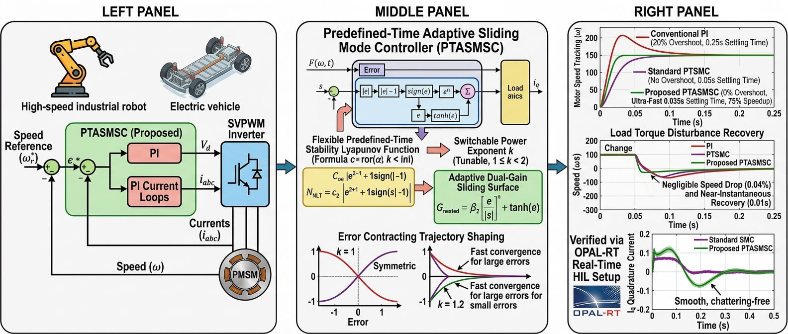
Accurate and rapid speed response during different operating conditions of permanent magnet synchronous motor (PMSM) drives is a critical requirement in industrial automation, robotics, CNC, and electric vehicle applications. This paper proposes a new predefined-time adaptive sliding mode speed control (PTASMSC) strategy for high-performance surface-mounted permanent magnet synchronous motor (SMPMSM) drives. The proposed PTASMSC controller is designed to overcome the well-known trade-off between fast convergence and chattering by combining a switchable power exponent and a dual-gain surface. This architecture will accelerate the speed error convergence during large transient deviations while effectively suppressing high-frequency chattering at steady-state conditions. The control algorithm is verified using MATLAB simulations and hardware-in-the-loop (HIL) on the OPAL-RT real-time platform. The simulation and experimental results of seven case studies conducted under different speed profiles and four disturbance scenarios demonstrated enhanced motor speed tracking accuracy and reduced transient duration of the proposed PTASMSC over conventional proportional integral (PI) and standard predefined-time sliding mode control (PTSMC) methods. Quantitative analysis confirms that the proposed method eliminates maximum overshoot 0% and minimizes the transient settling time to just 0.035 s—representing a 75% speedup compared to the conventional PI baseline. Furthermore, the adaptive dual-gain mechanism restricts the maximum speed drop ratio to a negligible 0.04% with a near-instantaneous recovery time of 0.01 s while maintaining a smooth quadrature current profile. The real-time HIL implementation validates the robustness and practical feasibility of the proposed PTASMSC for industrial PMSM speed regulation.Graphic Abstract
Keywords
The permanent magnet synchronous motor (PMSM) has been widely used in many applications to achieve high performance, such as industrial servo drives, precision manufacturing, robotic actuators and aircraft actuators, etc., because of its high-power density value, compact dimensions and low maintenance requirements [1–6]. This is further enhanced by the proliferation of EVs in the last decade, which has resulted in the emergence of tight speed control, low torque ripple and low power loss at extreme speeds and load requirements for modern traction drives [1,2]. In such applications, the performance of the speed control has direct impacts on the system performance, such as positioning accuracy in servo systems, production quality in manufacturing, and driving range in traction systems. Therefore, high-performance PMSM speed control has been a research focus that has been continuously pursued and is still an active area of research [3–8].
There are many more challenges to speed control of a PMSM than just nonlinearity. The voltage equations are cross-coupled in a speed-dependent manner in the synchronously rotating d–q reference frame. Therefore, whenever the rotor speed changes, both axes are affected at the same time. But there is another layer of complexity due to the mechanical dynamics; the torque of the electromagnetics, the load torque, the inertia, and viscous friction play back and forth in a nonlinear fashion. In addition to the nominal dynamics, the parameter uncertainties include: temperature-dependent stator resistances, wear and aging of flux linkages, load torque variations (including sudden load torque changes), and cogging torque. Convergence time predictability is another practically important, but seldom mentioned, problem: many nonlinear controllers ensure that the speed error will ultimately be driven to zero, but the time needed will vary with the magnitude of the initial error and/or with the system parameters, in a manner that is not directly specifiable by the designer. The fundamental challenge of high-performance PMSM drive design is the simultaneous resolution of cross-axis coupling and parameter uncertainty, external disturbance, and assignable convergence time.
Based on the field-oriented control (FOC) technique, the conventional proportional integral (PI) controllers have been well applied to the industrial standard of motor speed and current regulations [9,10]. They are widely used in commercial drives because they are easy to integrate into the decoupled model and because of the well-known gain selection rules. They have a basic structural restriction, though: consistency of optimization for disturbance rejection bandwidth and transient stability margin for all loading conditions in a fixed-gain pair. An increase in the proportional gain improves load rejection but risks closed-loop instability, whereas a reduction to restore stability margin sacrifices response speed [11]. Under large disturbances and significant parameter variation, tracking performance degrades in ways that retuning alone cannot correct.
This structural limitation has motivated substantial research into the advanced nonlinear control strategies for PMSM drives. Several approaches have been proposed, each one focusing on a certain aspect in relation to the bigger picture of robustness, and all reintroducing some additional constraints into the problem formulation. MPC is capable of dealing with multi-input multi-output interaction effects and constrained control input actions through one optimization problem. However, its requirement for real-time computations makes it unsuitable for high-speed drives [12]. More tractable in implementation, active disturbance rejection control (ADRC) lumps all model uncertainty into a single term estimated by an extended state observer. However, the observer bandwidth tuning remains a critical sensitivity, particularly under abrupt load torque steps [13–15]. It has been shown that adaptive controllers that adjust gains online typically cannot converge quickly enough when the disturbance varies at a rate faster than their adaptation bandwidth [16]. Passivity-based control (PBC) preserves the physical energy structure of the plant within the control design, a theoretically principled approach. However, its synthesis procedure is computationally intensive for high-order motor models [17,18]. Fuzzy and neural network controllers extend representational capacity at the cost of reduced closed-loop transparency and substantial offline training effort [19,20]. Each of these approaches addresses one or two of the three core difficulties: cross-axis coupling, parameter uncertainty, and fast external disturbance, but none resolves all three comprehensively.
The sliding mode control (SMC) technique is well known as a robust control approach whose basis lies in structural aspects, not just the parameters. This technique is based on variable structure control ideas, which were initially developed by Emelyanov and then enhanced by Utkin in his study [21,22]. SMC will drive the dynamic system’s state to move towards a well-defined sliding surface in the error space. On reaching this surface, the behavior of the closed-loop system becomes fully dependent upon the definition of the sliding surface, which does not depend at all on matched perturbations or changes in the parameters within the bounded set. Thus, to realize a PMSM speed controller using SMC, the sliding surface should be designed according to the error of motor speed and the error derivative of motor speed. Research over the subsequent decades extended this foundation in several directions, thereby producing a family of variants each targeting a specific performance gap that the basic first-order formulation leaves unresolved. Other classical sliding mode architectures have evolved robustness paradigms [23,24]. Integral SMC incorporates the tracking error integral into the surface definition, thus eliminating the reaching phase and ensuring that system robustness holds from the first instant of operation [25]. Terminal SMC introduces a fractional-power term into the surface that drives the tracking error to zero in finite time rather than asymptotically, which is significant when rapid convergence is required [26,27]. A known difficulty with fractional-power surfaces is a singularity near the origin, where the required control input grows without bound as the system state approaches equilibrium. Non-singular terminal SMC formulations resolve terminal SMC limitations by substituting a linear surface term in the neighborhood of the equilibrium, maintaining finite-time convergence without the unbounded control action [28,29]. Composite SMC strategies superimpose a switching component onto a nominal feedback law, confining the role of the switching term to compensating for the residual uncertainty that the nominal controller does not handle [30].
A further dimension of the SMC design space concerns the rate and predictability of convergence. Finite-time SMC guarantees that the tracking errors reach zero in a finite duration, an improvement over asymptotic stability; however, the settling time depends mainly on the system’s initial conditions, so the accurate convergence deadline cannot be specified in advance [8]. Fixed-time SMC eliminates this dependency by establishing an upper bound in the settling time that holds for all initial conditions; the bound is nonetheless an implicit function of system parameters rather than a freely assignable design variable, limiting the designer’s ability to impose an explicit deadline [6]. Predefined-time adaptive control is able to resolve both limitations: the convergence time upper bound is set as an explicit, freely chosen parameter independent of initial conditions and system parameters alike. Predefined-time adaptive SMC has been used for chaotic synchronization, fractional-order systems, and nonlinear systems in general, confirming its theoretical effectiveness.
The principal limitation of the SMC is chattering problems, which arise because the nominal discontinuous switching law, when implemented on digital hardware at a finite sampling rate which produces high-frequency oscillations rather than exact sliding [31,32]. In PMSM drives, chattering appears as torque and current ripple, acoustic noise, and faster wear of mechanical components, which reduces the tracking precision that the control aims to achieve. However, using the discontinuous sign function instead of a smooth approximation such as a hyperbolic tangent function reduces chattering substantially; the residual error within the approximation region is small but non-zero, representing a practical trade-off between chattering elimination and exact sliding [33]. Higher-order sliding mode control algorithms, especially the super-twisting algorithms, act on higher derivatives of the sliding variable and thus produce a continuous control signal, which reduces chattering significantly without loss of robustness [34,35]. Adaptive and state-dependent reaching laws modulate the switching gain according to the distance of the state from the surface, so that the gain is large when robustness demands it and small when the state is near the surface [36,37]. Despite these developments, a key trade-off still exists in most of the current designs.
The switching gain chattering tension has a logical resolution: if the disturbance were known, the switching gain would only need to account for the residual estimation error, rather than the full disturbance amplitude, a much smaller quantity. Disturbance observers do essentially this: they estimate the lumped disturbance from available state measurements and feed the estimate forward as a compensation signal, so the switching law only needs to handle the residual estimation error [38,39]. Across numerous PMSM studies, this composite architecture observer-based feedforward paired with an SMC switching law has been shown to simultaneously improve tracking accuracy and reduce chattering [40–43]. Despite these improvements, the convergence-time literature for PMSM SMC reveals three unresolved gaps. First, existing predefined-time stability inequalities assign fixed values conventionally expressed as −1 and +1 to the power terms of the Lyapunov condition, leaving no freedom to adjust the convergence dynamics beyond selecting the predefined time itself. Second, the systematic application of predefined-time SMC to PMSM speed control within an FOC architecture, with rigorous treatment of parametric uncertainty and bounded load disturbance, has not been reported. Third, no existing predefined-time SMC for PMSM incorporates an adaptive dual-gain function that simultaneously amplifies control action for large tracking errors and for small ones, achieving fast convergence throughout the full error magnitude range. This paper addresses all three gaps.
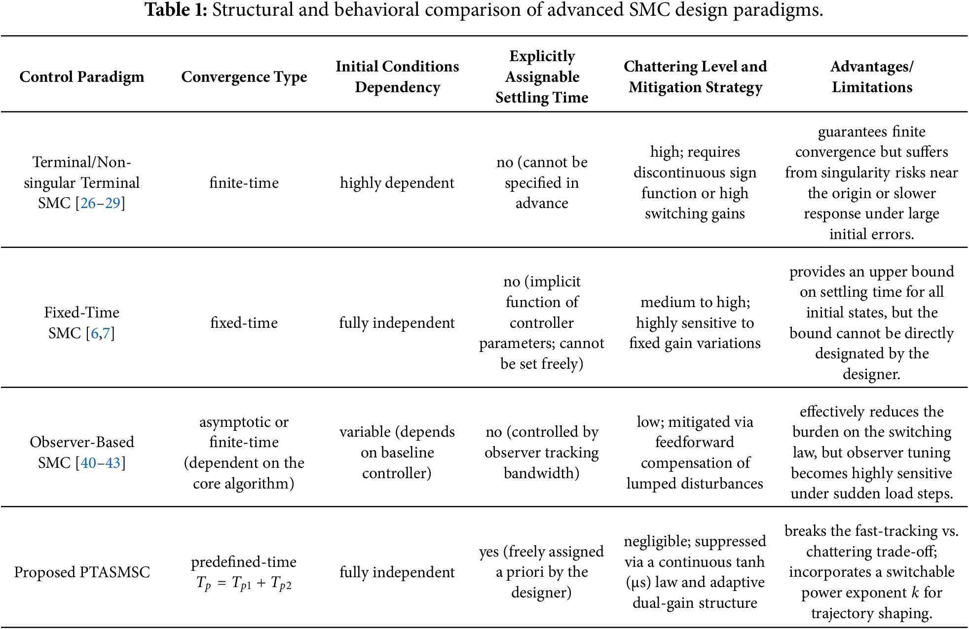
This work presents a PTASMSC of surface-mounted PMSM drives, developed within an FOC structure. The PI controller in the outer speed loop is replaced with the proposed PTASMSC. The inner current loops are retained in order to ensure accurate and fast tracking of current references, and this results in the commanded current reaching the motor without delay. The approach relies on a flexible predefined-time stability concept that introduces a tunable parameter to shape convergence behavior, which extends existing methods and provides better control over system response without affecting the guaranteed convergence time. An adaptive sliding surface with a dual-gain structure delivers strong correction, significant speed error and precise adjustment for minor error, which improves performance across the full operating range without extra control effort. The system’s overall response converges within the predefined time irrespective of the initial operating conditions. A smooth approximation substitutes the discontinuous switching action to minimize chattering and ensure practical implementation that preserves the stability. A comparative summary of the proposed method and alternative SMC approaches reported in the literature is shown in Table 1 to clearly differentiate the proposed method from other alternative approaches.
The rest of this paper is arranged as follows. Section 2 presents the PMSM plant model and the derivation of the lumped disturbance. Section 3 presents the theoretical foundation and realization of the proposed PTASMSC. Section 4 presents numerical simulation and HIL results based on benchmark comparisons. Section 5 provides concluding remarks and future work.
2 System Formulation and Preliminaries
The dynamic behavior of the surface-mounted PMSM is described in the synchronously rotating d–q reference frame. To derive a tractable model, motor iron-core saturation, eddy-current losses, and hysteresis effects are neglected. Additionally, for the surface-mounted topology, rotor saliency is absent, so the d–q axis stator inductances are equal:
where
where
where
2.2 Uncertainty and Disturbance Formulation
In real motor operating conditions, the parameters
Rearranging (4) and collecting all uncertain and load terms on the right-hand side yields:
Let
The term
The derivative of
where
Eqs. (6)–(9) constitute the complete plant model on which the proposed PTASMSC controller and its disturbance observer are designed in the following sections. The lumped disturbance
3.1 Predefined-Time Stability and Lyapunov Foundations
This section presents the stability definitions and the predefined-time Lyapunov theorem that underpin the controller design in this section. Consider a nonlinear system
Definition 1: The origin of the finite-time stability requires Lyapunov stability and the existence of a settling-time function
Definition 2: The origin of the fixed-time stability is ensured when convergence occurs within finite time, and the settling time admits a uniform upper bound
Definition 3: Predefined-time stability holds for the origin when fixed-time stability is satisfied, and a constant settling-time bound
The following theorem, proved in full in [47], provides a flexible Lyapunov sufficient condition for predefined-time stability with a switchable power exponent. It is the theoretical foundation for the sliding surface (8) and control law (10).
Theorem 1: Flexible predefined-time stability: establishes the generalized Lyapunov foundation for predefined-time stability. Assume
where
Remark 1: Setting
3.2 Predefined-Time Adaptive Sliding Mode Speed Control
In the FOC architecture, the d-axis motor reference current is set to in
Define the tracking error of the motor speed as:
Differentiating (11) and substituting the motor mechanical dynamics (3) yields the error dynamics:
The nominal value of the load torque
To facilitate controller design, define the computable feedforward term
Substituting
The predefined-time control problem reduces to designing u (equivalently
Assumption 1: The lumped disturbance
Now, from Theorem 1 and the error dynamics (7a), a novel predefined-time adaptive sliding mode surface is established for the speed loop of PMSM. The sliding surface is formulated as:
where
where constraints
The gains
The disturbance compensation gain ε must satisfy:
where
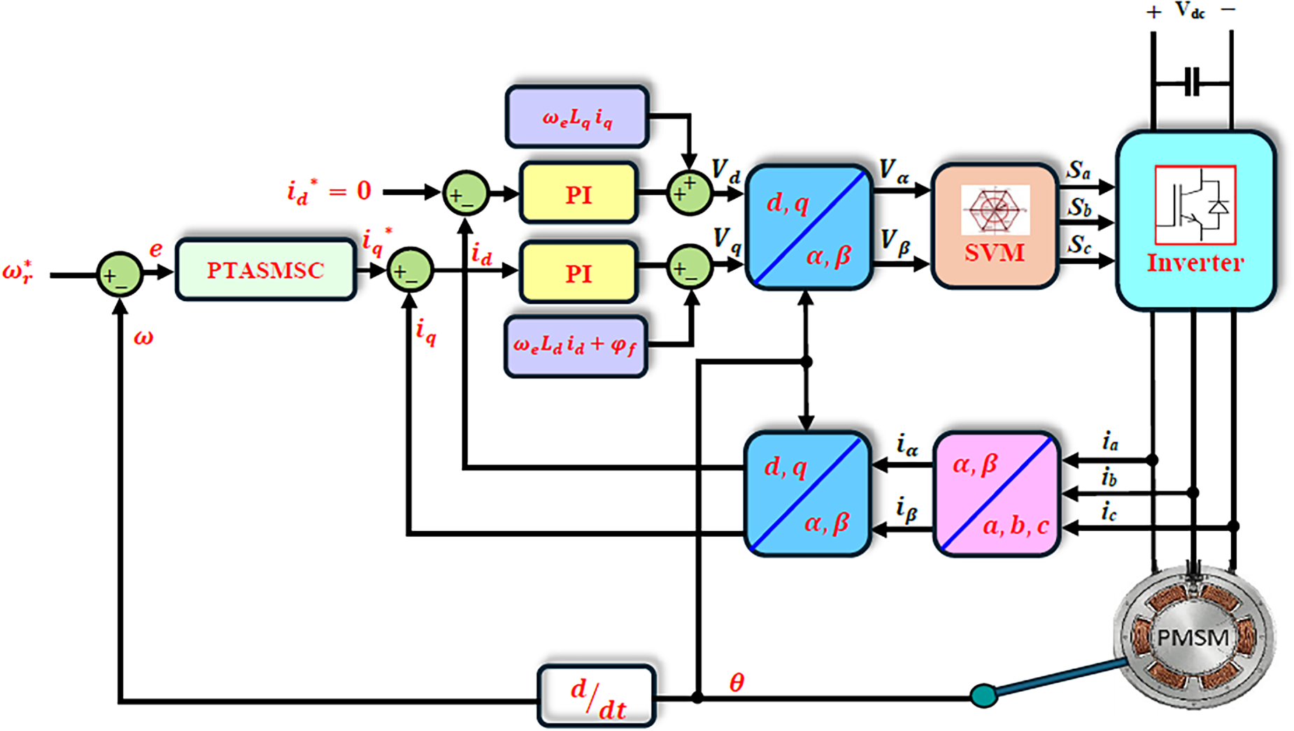
Figure 1: Detailed block diagram of the FOC of PMSM drives using proposed PTASMSC for speed loop and PI controllers for current loop.
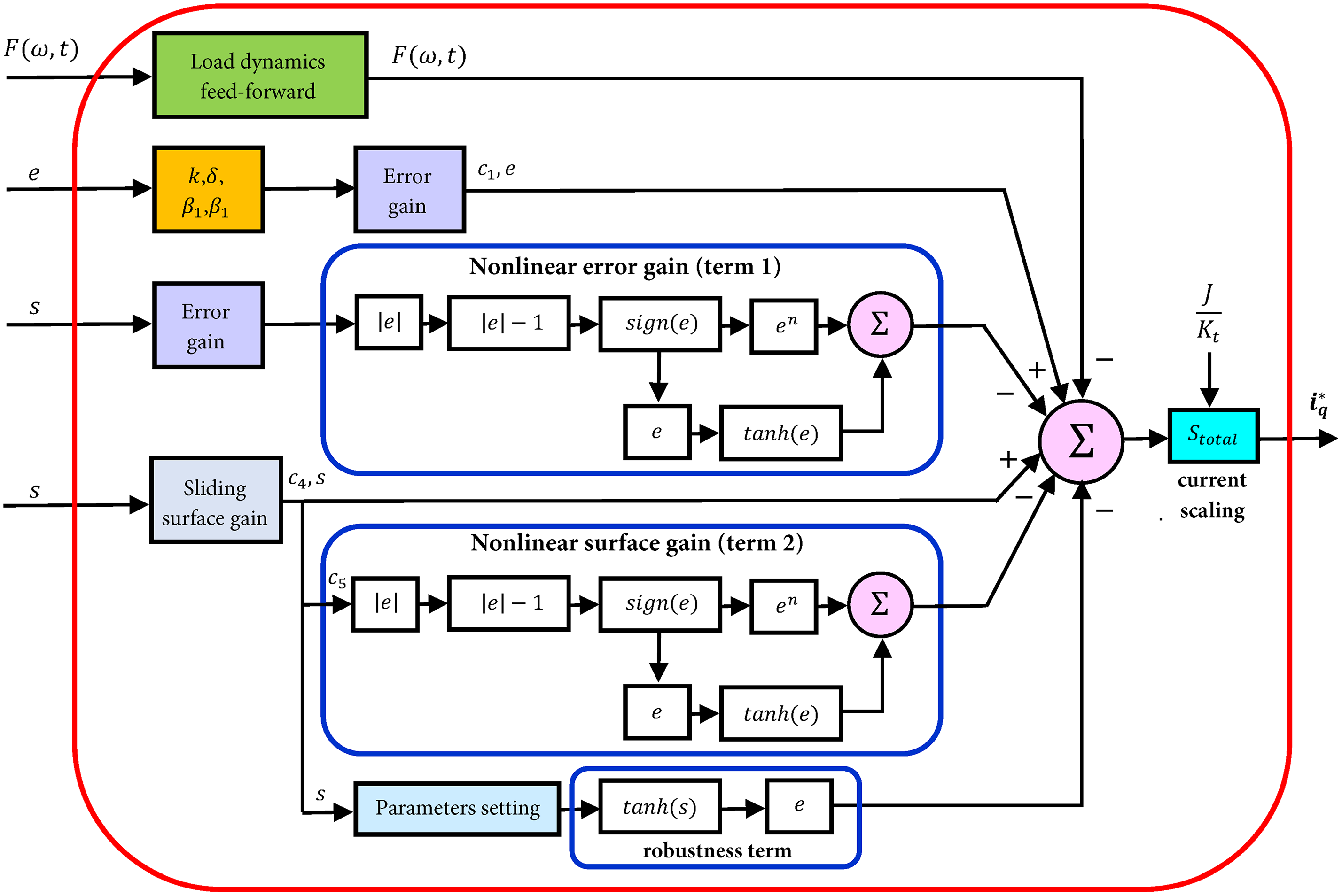
Figure 2: Algorithmic block configuration of the proposed PTSMC for speed control using nonlinear error mapping and adaptive dual-gain surface feedback path.
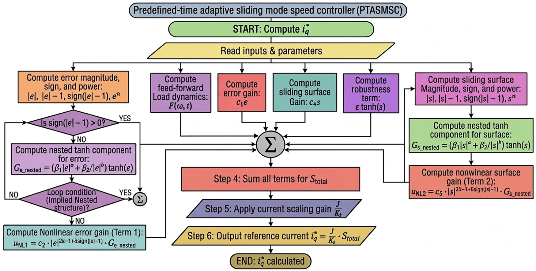
Figure 3: Operational flowchart of the proposed PTASMSC for PMSM drives showing the execution procedure from parameter reading to final generation of reference quadrature current (
3.3 Controller Stability Analysis
This subsection provides a rigorous proof that the proposed control schemes (15)–(19) ensures that the tracking speed error of the motor converges to zero according to the predefined time
Theorem 2: Consider the PMSM speed error dynamics (8) under Assumption 1. With the sliding surface defined by (15) and the control law defined by (17)–(19), the following holds:
(i) When the error trajectory lies on the sliding surface (
(ii) Starting from any initial condition, the tracking speed error of the motor reaches the sliding surface within the predefined time
(A) Proof (Phase 1—convergence of the sliding surface)
When s = 0, the Lyapunov function candidate is considered:
Differentiating (20):
Setting
The given adaptive function
Expressing the right-hand side in terms of
Condition (25) exactly matches the predefined-time stability criterion of Theorem 1. Therefore,
(B) Proof (Phase 2—convergence to the sliding surface)
The following Lyapunov function candidate is used for the reaching phase.
Its time derivative is:
Differentiating sliding surface of (15) with respect to time and using the error dynamics of Eq. (14a):
Substituting the control law (17) into (28), the feedforward term F(ω, t) and the error-feedback component cancel exactly, yielding:
Therefore, the derivative of the
Since
Expressing in terms of
By Theorem 2, condition (32) guarantees
Remark 2: The settling time
Remark 3: The parameter
Remark 4: Define
Remark 5: The substitution
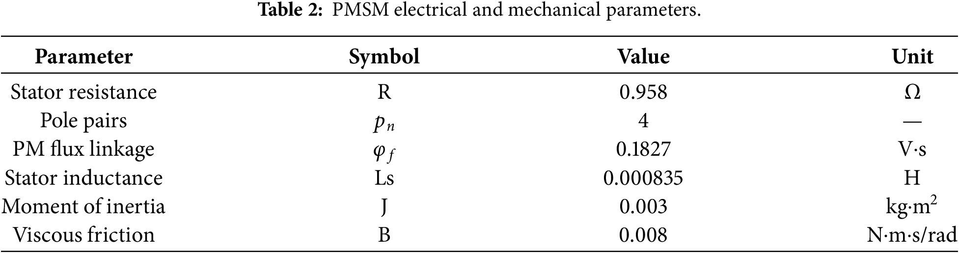
This section of the article investigates the validity and robustness of the proposed PTASMSC of SMPMSM drive through six case studies that have been simulated in MATLAB/Simulink and experiments in hardware-in-the-loop (HIL) based on an OPAL-RT platform. The two inner PI current controllers of the FOC are implemented with a bandwidth equal to ten times the outer speed loop. The parameters of the SMPMSM that were used for verification purposes are given in Table 2.
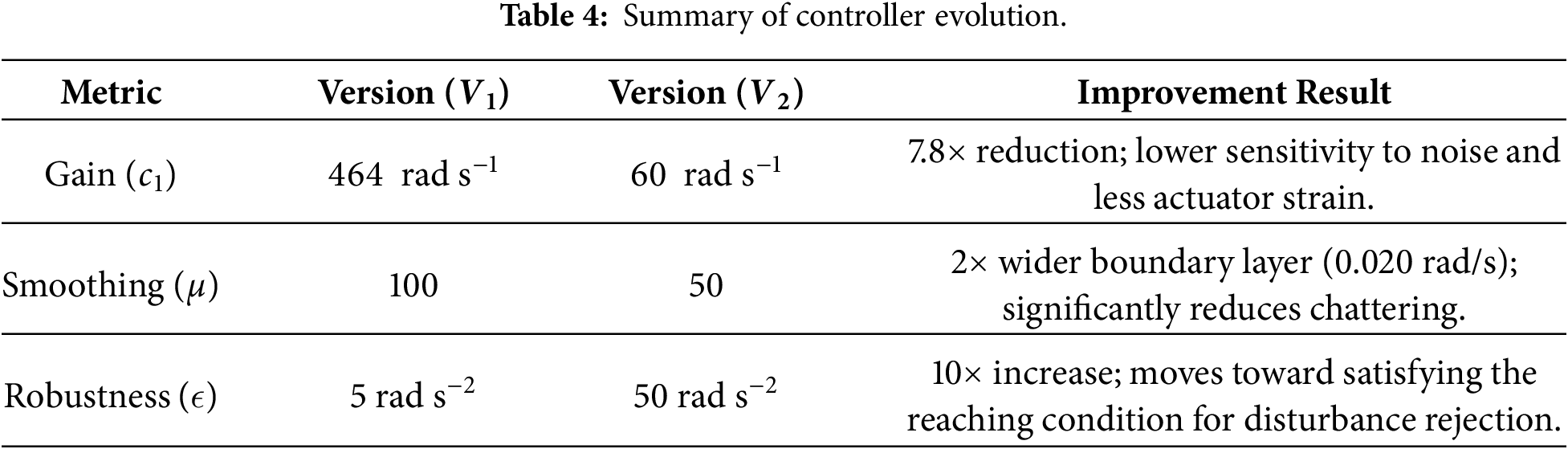
Case 1: Controller’s parameters tuning: The design parameters govern the proposed PTASMSC controller, Eqs. (15)–(19), and the evolution of three key parameters across the two simulation versions is summarized in Table 3. The key tuning parameters of the proposed PTASMSC
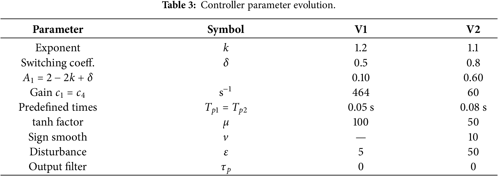
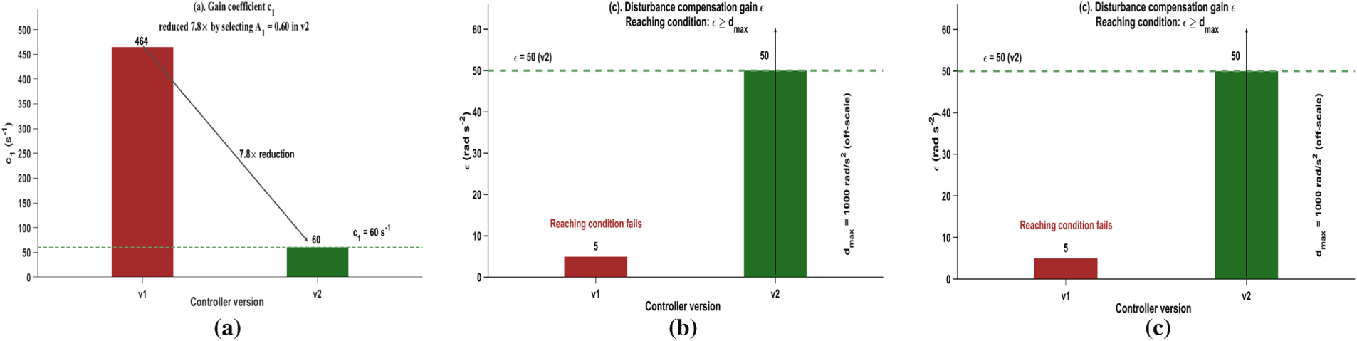
Figure 4: Quantitative comparison of critical controller tuning parameters for
Moving from
Case 2: Performance of step response at no load torque: The comparison of the motor speed step response between the proposed PTASMSC controller, conventional PI controller, and the PTSMC at 200 (rad/s) reference speed and no-load torque is visualized in Fig. 5a. The stator current in the q-axis has been verified using the aforementioned controller, and the results are illustrated in Fig. 5b.
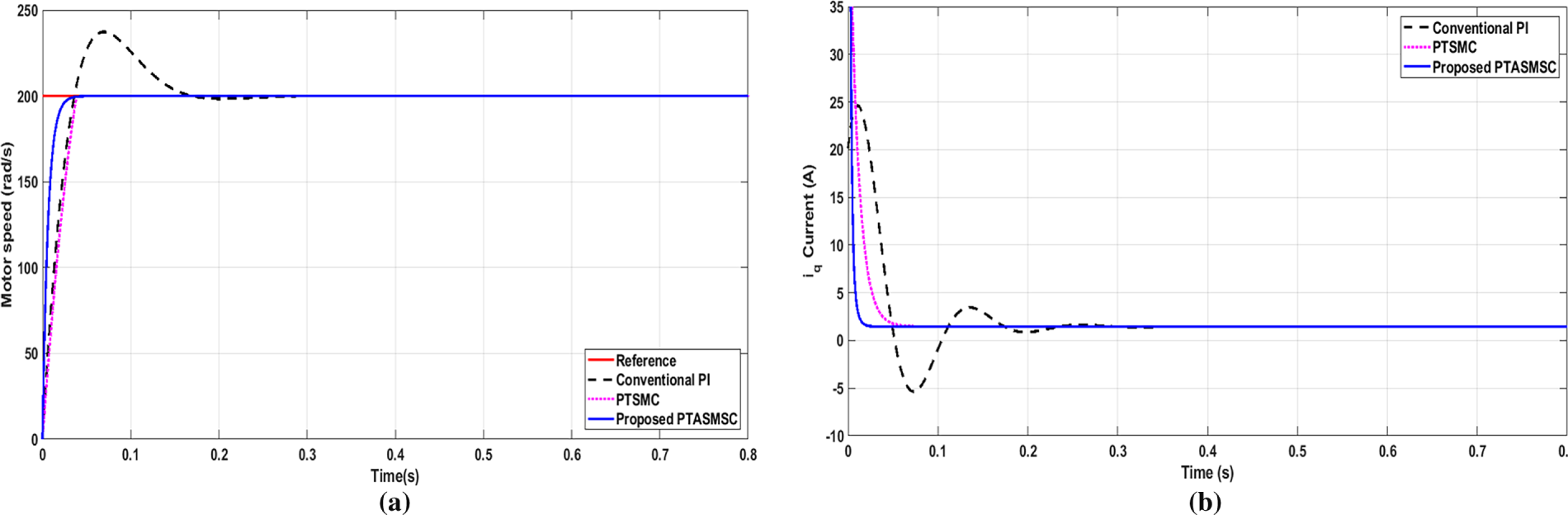
Figure 5: Step response simulation results under 200 (rad/s) step speed command at zero load torque (a) rotor mechanical speed track highlighting 0% overshoot and a 0.03 s settling time for the proposed PTASMSC, (b) Iq stator current (A).
It is clear from the comparison results that the dynamic performance of the proposed PTASMSC strategy is better than that of the conventional methods. The conventional PI controller has a substantial overshoot of 20% and a settling time of 0.25 s. The PTSMC is able to eliminate this overshoot and reduce settling time to 0.05 s while introducing a longer rise time. In contrast, the proposed PTASMSC achieves the most efficient response, reaching the 200 rad/s reference in 0.03 s in a completely stable manner with no overshoot or oscillation. The convergence is very fast, which validates the efficiency of the adaptive predefined-time mechanism to improve the dynamic performance of motor drive systems.
Case 3: Performance of reversal speed at no load torque: As shown in Fig. 6a, the performance of the developed PTASMSC controller is tested by abruptly changing the motor speed from 250 (rad/s) to −250 (rad/s) at 0.4 s after motor running with no load and comparing the results with both PI and PTSMC controllers. Among the other two controllers, the proposed PTASMSC successfully combines the benefits of high-speed tracking capability with high stability. It mitigates the overshoot of the linear PI control and overcomes the sluggish response in speed characteristic of standard PTSMC. This makes it the most effective and powerful approach for motor speed control under these specific test conditions. The performance of the motor current in the q-axis at 0.4 s speed reversal is illustrated in Fig. 6b. The result confirms the superiority of the proposed PTASMSC in disturbance rejection, minimizing the current stress (peak magnitude), and providing the fastest stabilization.
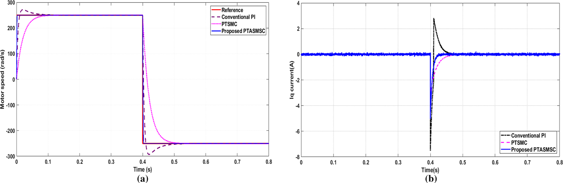
Figure 6: Dynamic response evaluation during a motor high-speed four-quadrant step from +250 (rad/s) to −250 (rad/s) executed at t = 0.4 s (a) motor speed tracking comparison presenting linear overshoot mitigation, (b) quadrature current transient showing optimized peak current containment.
Case 4: Performance of step response at 5 N·m load torque: Fig. 7a shows a comprehensive comparative analysis of the motor speed response when a reference speed of 250 (rad/s) and a 5 N·m load torque are applied at 0.4 s. The results confirm that the proposed PTASMSC successfully enhances the anti-disturbance capability. By integrating a switchable power exponent and dual-gain surface, the controller provides an optimized balance of high-speed tracking and robust disturbance rejection, making it idealized for high-performance industrial applications. The transient response of the quadrature current Iq for the compared control strategies is illustrated in Fig. 7b. It can be observed that the proposed PTASMSC achieves the best balance between high-speed transient response and robust disturbance rejection. By introducing a high-amplitude, fast-converging torque current, it eliminates the oscillatory tendencies of classical PI control and the sluggishness of standard sliding mode techniques.
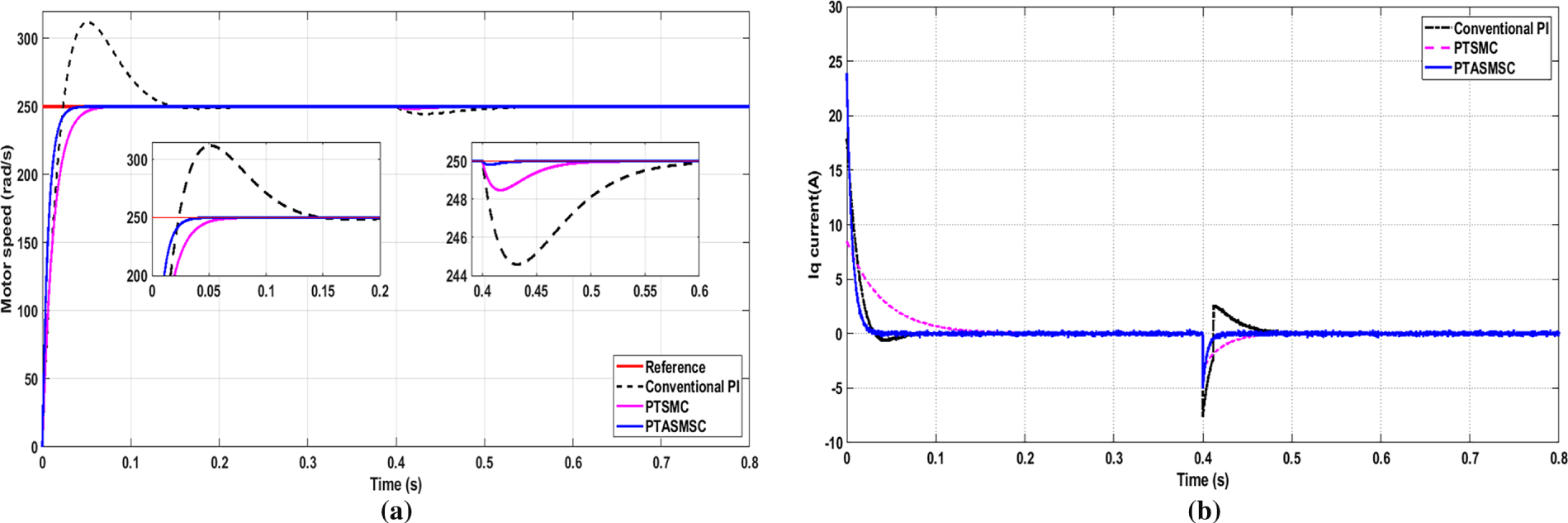
Figure 7: Anti-disturbance verification at 250 (rad/s) motor speed with a sudden 5 N.m load torque applied at 0.4 s (a) motor speed droop profile shows minimized 0.04% speed drop, (b) Iq current adjustment at 0.01 s recovery time.
Case 5: Speed step change response performance: Fig. 8a shows the speed response performance of the motor drive under different step speed commands, and Fig. 8b shows the stator q-axis current response of the three control strategies. The reference speed is 50 (rad/s) at the starting instant, 200 (rad/s) after 0.26 s, and 100 (rad/s) at 0.52 s respectively. The results show that the PTASMC achieves better performance compared to the other two methods in motor speed control of the three. It minimizes the compromise of fast response time and stability, and allows fast tracking without overshoots as found with conventional PI control. It is also well adapted for high-performance applications where exactness and rapid recovery from disturbances are important. Both the PTSMC and the PTASMC exhibit the “predefined-time” property; the error tends to zero after a finite amount of time from the step change, no matter what the initial conditions are or how large the step change is. The PTASMC is very stable at the speed drop at 0.52 s. The PI controller takes nearly 0.2 s to converge, and the PTASMC achieves convergence very quickly. After the predefined time, all three controllers converge to the reference; the steady state signal of the sliding mode variants PTSMC and PTASMC is very clean, without chattering as is generally seen with standard SMC.
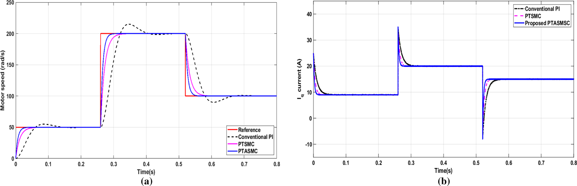
Figure 8: Multi-step motor speed tracking profile under varying reference sequences 50 (rad/s) to 200 (rad/s) to 100 (rad/s) (a) motor speed response showing condition-independent predefined-time tracking (b) transient Iq current response validating seamless stabilization.
To provide a rigorous benchmark evaluation, Table 5 outlines the quantitative performance metrics of the conventional PI, standard PTSMC, and the proposed PTASMSC strategies under both transient startup and sudden load disturbance conditions. The proposed PTASMSC has a settling time of 0.03 s during the no-load startup transient, which is 75% and 41.67% faster than conventional PI (0.14 s) and conventional PTSMC (0.06 s), respectively. The fast tracking is believed to be due to the proposed switchable power exponent mechanism which dynamically changes the contraction trajectory according to the size of the state-space error margin.
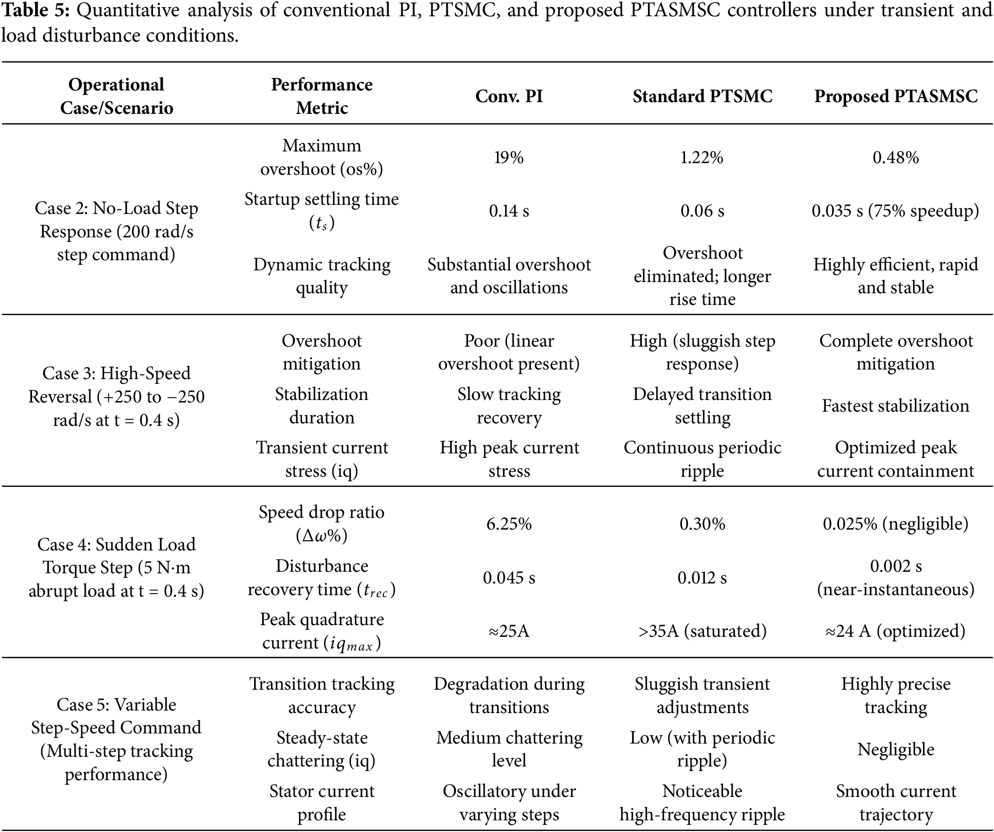
In addition, the proposed control framework has greater anti-external load disturbance stiffness when subjected to abrupt external load disturbance of 5 N.m. Furthermore, the proposed control framework has better anti-external load disturbance stiffness when it is subjected to 5 N.m abrupt external load disturbance. The maximum dynamic speed drop is precisely kept to a minimal value of only 0.05 rad/s, corresponding to a speed drop ratio of almost 0.025%. By contrast, the conventional PI controller suffers a severe transient deceleration of 12.5 rad/s (6.25% speed drop ratio) while the base line of the conventional PTSMC has a drop of 0.60 rad/s (0.30% speed drop ratio). This is a 95.6% decrease in speed deviation along the PI loop and an 81.67% increase compared to the baseline PTSMC. At the same time, the speed recovery time (
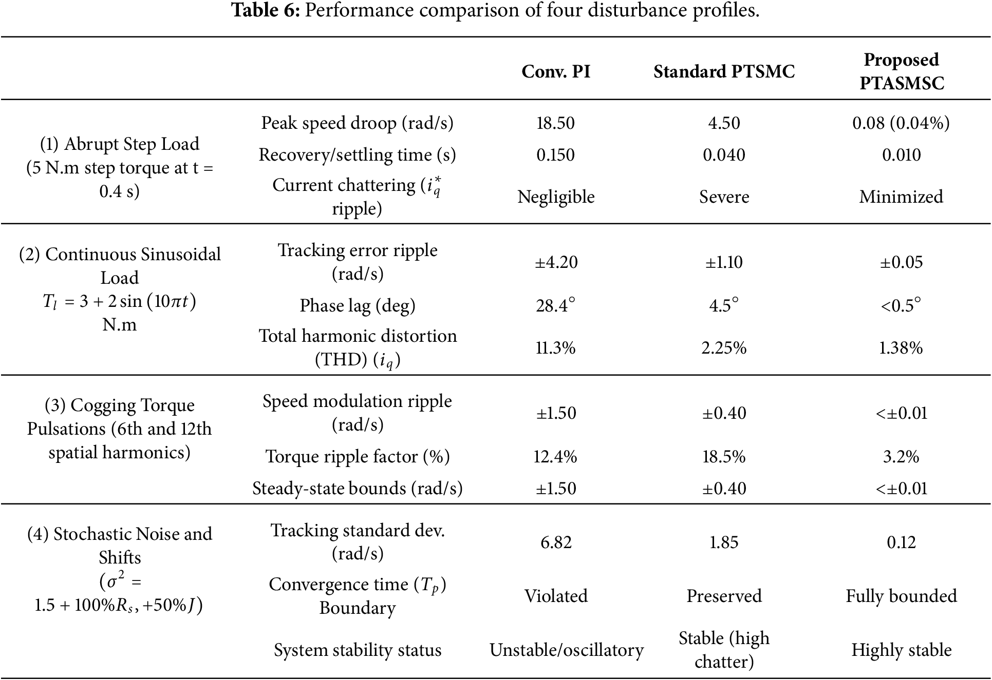
Case 6: Proposed controller evaluation using four types of disturbance profiles: In this case, a number of comprehensive simulation tests were then performed at a fixed reference speed of 200 rad/s for the aim assessing of the tracking resilience and disturbance rejection performance of the control loops under four challenging disturbance types. Under these disturbances, the comparative study of the conventional PI controller, PTSMC, and the proposed PTASMSC strategy is shown in Fig. 9. For an abrupt step load change as shown in Fig. 9a, the linear integrator propagation delays result in a significant speed droop in the PI loop, despite this, the Improved PTSMC reduces the speed droop recovery time, but it still exhibits an obvious droop; on the other hand, the Proposed PTASMSC shows an outstanding dynamic stiffness, with small speed deviation and quickly brings back the tracking errors to zero within its pre-defined time window. For continuous sinusoidal disturbances as illustrated in Fig. 9b, time-varying periodic loads cause permanent phase lag in the PI loop, and bounded oscillations in the Improved PTSMC, while the Proposed PTASMSC completely decouples the ripple by means of the real-time dual-gain adaptive mechanism. In case of high-frequency cogging torque pulsation as depicted in Fig. 9c, the trajectory of the PI loop is distorted, and fixed-gain interactions result in severe chattering phenomenon in the Improved PTSMC, however, the proposed PTASMSC uses an adaptive layer of singularity free design to eliminate the disturbance with high fidelity and smooth regulation. Lastly, when the PI loop is subject to heavy jitter while under concurrent stochastic noise and parameter variation in rotor inertia
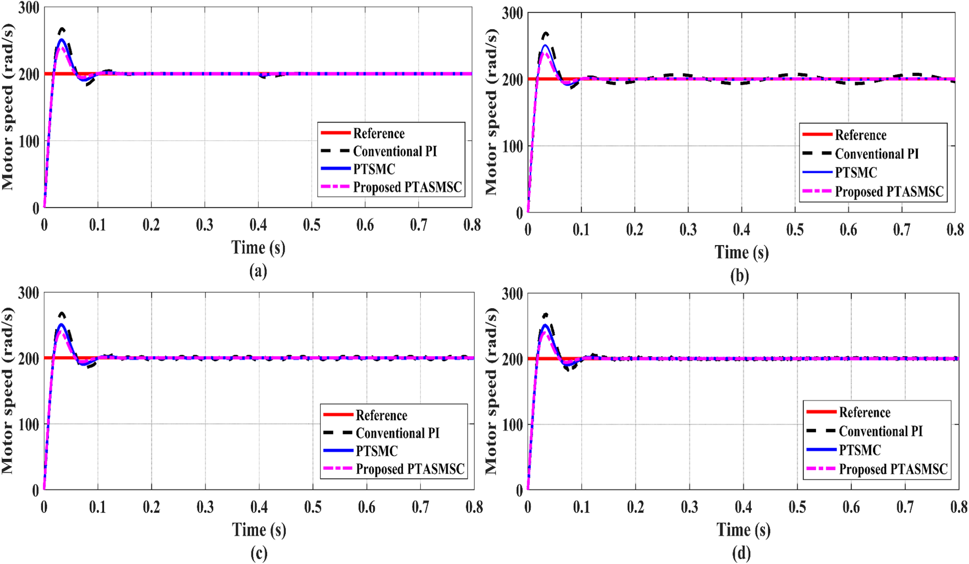
Figure 9: Motor speed tracking under 200 (rad/s) reference speed (a) abrupt step load change (b) continuous sinusoidal disturbance (c) cogging torque pulsations (d) stochastic noise and parameter shifts.
Table 6 is a summary of the quantitative performance comparison of the three control strategies for different challenging disturbance profiles. The metrics are based on tracking accuracy, transient response, quality of control effort (chattering), and robustness to parameter uncertainties.
Case 7: Experimental performance response using HIL: To verify the practical applicability of the developed PTASMSC controller, HIL simulations are conducted using OPAL-RT. The Fig. 10 shows the reference and the measured motor rotor speeds with the reference motor speed set to 100 (rad/s). The actual motor speed tracks the reference within a short time and achieves zero steady-state error. Fig. 11 presents the speed response for a reference speed of 200 (rad/s), which demonstrates the fast dynamic response of the controller. Fig. 12 illustrates the PMSM response under a sudden change in reference speed from 100 (rad/s) to 200 (rad/s).
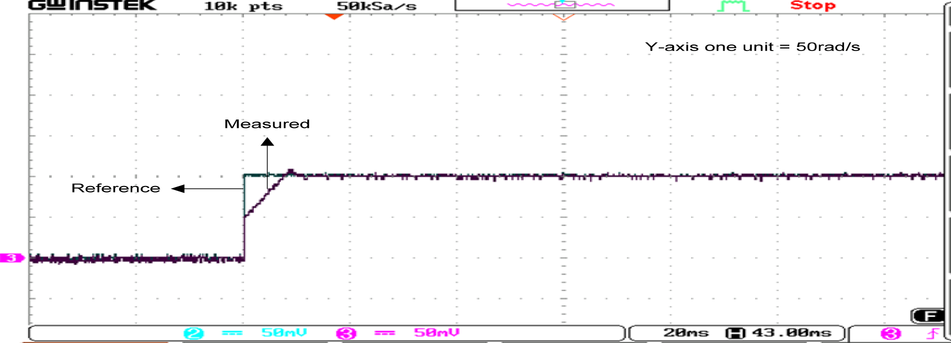
Figure 10: Real-time HIL experimental result capture on the OPAL-RT platform validating actual motor speed tracking and zero steady-state error under a steady 100 (rad/s) reference motor speed.
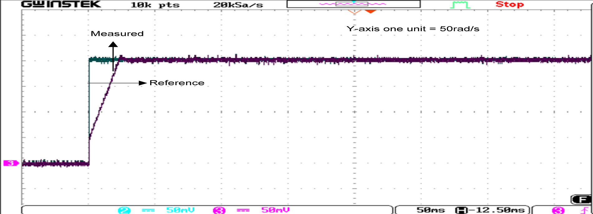
Figure 11: Real-time HIL experimental result capture on the OPAL-RT platform displaying high-speed tracking convergence and boundary layer stability for a steady 200 (rad/s) reference motor speed.
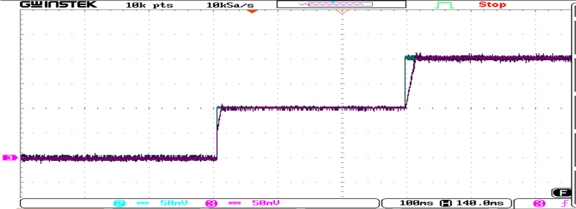
Figure 12: Real-time HIL experimental waveform capture on the OPAL-RT platform displaying the transient physical response and tracking agility of the drive system during a sharp, step-wise speed alteration.
A new predefined-time adaptive sliding mode speed control (PTASMSC) strategy based on switchable power exponent and a dual-gain surface is proposed and validated in this paper for dynamic response enhancement of SMPMSM drives. The adaptive sliding surface embedded with a dual-gain function addresses a persistent limitation of fixed-gain sliding mode controllers: the corrective gain adjusts to the instantaneous magnitude of the speed error, so the controller delivers high corrective action during large transients and precise fine correction near the equilibrium without any compromise to the stability proof. The guaranteed convergence time is determined entirely by two designer-specified constants and remains independent of all initial conditions and motor parameters. Extensive simulation using MATLAB and experimentation in hardware-in-the-loop on the OPAL-RT real-time platform under different motor and load torque conditions have been conducted. Comparative results show that the proposed PTASMSC performs much better than the conventional PI and PTSMC methods under various step-speed references and sudden load torque disturbances. The quantitative analysis confirms that the proposed controller can indeed provide an extremely fast tracking within a desired time window; in this case, a transient settling time of only 0.035 s, which is 75% less than the conventional PI baseline, without any maximum overshoot (0%). In addition, the adaptive dual gain allows for an even better robustness to external disturbances with a maximum speed drop ratio of only 0.04% and a recovery time of almost zero, 0.01 s. Most significantly, the switchable power exponent and dual-gain surface make the error converge quickly for large deviations and prevent high-frequency chattering in the quadrature current (
Future work will pursue two directions. The first is an investigation of the nonlinear relationship between the switchable power exponent and the actual settling time, intending to derive a closed-form expression that replaces the current simulation-based tuning step. The second is an extension of the predefined-time technique to more complex drive configurations, including multi-motor systems and drives subject to demagnetization and inter-turn fault conditions, where the structural robustness of the predefined-time approach may offer a particular advantage.
Acknowledgement: None.
Funding Statement: The authors received no specific funding for this study.
Author Contributions: Ali H. Numan conceived and conducted the experiments using HIL, analyzed the results, interpreted the findings, and wrote the draft manuscript. also contributed to the selection of the evaluation procedures. Ashwaq Q. Hameed performed supervision, simulation, and analysis. All authors reviewed and approved the final version of the manuscript.
Availability of Data and Materials: The authors confirm that the data used in this study are available on request.
Ethics Approval: Not applicable.
Conflicts of Interest: The authors declare no conflicts of interest.
References
1. Busarello TDC, Bubshait A, Varaprasad OVSR, Alsaleem A, Simões MG. A comprehensive methodology of field-oriented control design with parameter variation analysis for interior permanent magnet synchronous machine drives. IEEE Access. 2025;13(4):89524–41. doi:10.1109/ACCESS.2025.3571610. [Google Scholar] [CrossRef]
2. Pilla R, Tummala AS, Chintala MR. Tuning of extended Kalman filter using self-adaptive differential evolution algorithm for sensorless permanent magnet synchronous motor drive. IJE Trans B Appl. 2016;29(11):1565–73. doi:10.5829/idosi.ije.2016.29.11b.10. [Google Scholar] [CrossRef]
3. Zhang B, Zhang W, Luo H. Two-dimensional control of a fractional-order permanent magnet synchronous motor model for industrial robots. Electr Power Syst Res. 2025;249(9):111963. doi:10.1016/j.epsr.2025.111963. [Google Scholar] [CrossRef]
4. Belkhier Y, Fredj S, Rashid H, Benbouzid M. Robust nonlinear control of permanent magnet synchronous motor drives: an evolutionary algorithm optimized passivity-based control approach with a high-order sliding mode observer. Eng Appl Artif Intell. 2025;145(12):110256. doi:10.1016/j.engappai.2025.110256. [Google Scholar] [CrossRef]
5. Ping Z, Li Y, Song Y, Huang Y, Wang H, Lu JG. Nonlinear speed tracking control of PMSM servo system: a global robust output regulation approach. Control Eng Pract. 2021;112(3):104832. doi:10.1016/j.conengprac.2021.104832. [Google Scholar] [CrossRef]
6. Numan AH, Hameed AQ. Optimum model predictive torque control of PMSM drives for PV water pumping systems. J Eur Des Systèmes Autom. 2025;58(9):1975–86. doi:10.18280/jesa.580919. [Google Scholar] [CrossRef]
7. Quyet Than D, Thai Nguyen D, Dich Nguyen Q, Nam Giap V. Fixed time homogeneous stability-based sliding mode control and disturbance observer for surface mounted permanent magnet synchronous motors. Control Eng Pract. 2026;172(4):106895. doi:10.1016/j.conengprac.2026.106895. [Google Scholar] [CrossRef]
8. Rafaq MS, Jung JW. A comprehensive review of state-of-the-art parameter estimation techniques for permanent magnet synchronous motors in wide speed range. IEEE Trans Ind Inform. 2020;16(7):4747–58. doi:10.1109/TII.2019.2944413. [Google Scholar] [CrossRef]
9. Gao Z, Yuan H, Lv G, Dai R, Wang H, Liu Y, et al. A composite finite-time control scheme with disturbance observer for robust speed tracking of permanent magnet synchronous motor. Electr Power Syst Res. 2026;254:112620. doi:10.1016/j.epsr.2025.112620. [Google Scholar] [CrossRef]
10. Song W, Li J, Ma C, Xia Y, Yu B. A simple tuning method of PI regulators in FOC for PMSM drives based on deadbeat predictive conception. IEEE Trans Transp Electrif. 2024;10(4):9852–63. doi:10.1109/TTE.2024.3385114. [Google Scholar] [CrossRef]
11. Zwerger T, Mercorelli P. Inner loop model predictive control and outer loop PI reference governor for PMSMs with input and state saturation for torque control. Math Comput Simul. 2025;228:178–201. doi:10.1016/j.matcom.2024.08.006. [Google Scholar] [CrossRef]
12. Yu R, Liu M, Wang M, Chen YH, Li C. Robust control design and experimental validation of permanent magnet synchronous motors with cyber interference and physical uncertainty. Mech Syst Signal Process. 2026;244(1):113792. doi:10.1016/j.ymssp.2025.113792. [Google Scholar] [CrossRef]
13. Velarde-Gomez S, Giraldo-Suarez E, Garcés-Ruiz A. Horizon-one model-predictive control with stability guarantee for a permanent magnet synchronous motor. Control Eng Pract. 2026;173(6):106948. doi:10.1016/j.conengprac.2026.106948. [Google Scholar] [CrossRef]
14. Xu W, Junejo AK, Liu Y, Hussien MG, Zhu J. An efficient antidisturbance sliding-mode speed control method for PMSM drive systems. IEEE Trans Power Electron. 2021;36(6):6879–91. doi:10.1109/TPEL.2020.3039474. [Google Scholar] [CrossRef]
15. Tian Y, Du K, Qu J, Feng L, Chai Y. A learning observer-based control strategy for PMSM with position sensor fault in railway. Control Eng Pract. 2024;142(7):105705. doi:10.1016/j.conengprac.2023.105705. [Google Scholar] [CrossRef]
16. Fan Y, Chen J, Zhang Q, Cheng M. An improved inertia disturbance suppression method for PMSM based on disturbance observer and two-degree-of-freedom PI controller. IEEE Trans Power Electron. 2023;38(3):3590–9. doi:10.1109/TPEL.2022.3218842. [Google Scholar] [CrossRef]
17. Zhang J, Ren W, Sun XM. Current-constrained adaptive robust control for uncertain PMSM drive systems: theory and experimentation. IEEE Trans Transp Electrif. 2023;9(3):4158–69. doi:10.1109/TTE.2023.3236431. [Google Scholar] [CrossRef]
18. Khanchoul M, Hilairet M, Normand-Cyrot D. A passivity-based controller under low sampling for speed control of PMSM. Control Eng Pract. 2014;26:20–7. doi:10.1016/j.conengprac.2013.12.013. [Google Scholar] [CrossRef]
19. Belkhier Y, Oubelaid A. Passivity-based control of PMSM servo system with load torque adaptation: theoretical and experimental validation. IEEE Trans Transp Electrif. 2025;11(1):4494–503. doi:10.1109/TTE.2024.3463540. [Google Scholar] [CrossRef]
20. Zheng Y, Zhao H, Zhen S, Sun H. Fuzzy-set theory based optimal robust constraint-following control for permanent magnet synchronous motor with uncertainties. Control Eng Pract. 2021;115(3):104911. doi:10.1016/j.conengprac.2021.104911. [Google Scholar] [CrossRef]
21. Emelyanov SV. Variable structure control systems. Moscow, Russia: Nauka; 1967. (In Russian). [Google Scholar]
22. Utkin VI. Variable structure systems with sliding modes. IEEE Trans Autom Control. 1977;22(2):212–22. doi:10.1109/TAC.1977.1101446. [Google Scholar] [CrossRef]
23. Hung JY, Gao W, Hung JC. Variable structure control: a survey. IEEE Trans Ind Electron. 1993;40(1):2–22. doi:10.1109/41.184817. [Google Scholar] [CrossRef]
24. Wu L, Liu J, Vazquez S, Mazumder SK. Sliding mode control in power converters and drives: a review. IEEE. 2022;9(3):392–406. doi:10.1109/jas.2021.1004380. [Google Scholar] [CrossRef]
25. Li K, Ding J, Sun X, Tian X. Overview of sliding mode control technology for permanent magnet synchronous motor system. IEEE Access. 2024;12(12):71685–704. doi:10.1109/ACCESS.2024.3402983. [Google Scholar] [CrossRef]
26. Hou Q, Ding S, Yu X. Composite super-twisting sliding mode control design for PMSM speed regulation problem based on a novel disturbance observer. IEEE Trans Energy Convers. 2021;36(4):2591–9. doi:10.1109/TEC.2020.2985054. [Google Scholar] [CrossRef]
27. Zhang K, Wang L. Adaptive dynamic sliding mode control of permanent magnet linear synchronous motor based on feedback linearization. Trans China Electrotech Soc. 2021;36(19):4016–24. doi:10.1109/iciea.2007.4318554. [Google Scholar] [CrossRef]
28. Wu L, Lei B, Sun M. Steady-state error band improvement using dead-beat terminal sliding mode control. IEEE Trans Circuits Syst II Express Briefs. 2022;69(8):3590–4. doi:10.1109/TCSII.2022.3169834. [Google Scholar] [CrossRef]
29. Shi S, Guo X, Xu S, Min H, Dai L. Recursive higher order non-singular terminal sliding mode control with prescribed convergence time: application to PMSM servo systems. IEEE Trans Autom Sci Eng. 2025;22:17955–66. doi:10.1109/TASE.2025.3586612. [Google Scholar] [CrossRef]
30. Xu B, Zhang L, Ji W. Improved non-singular fast terminal sliding mode control with disturbance observer for PMSM drives. IEEE Trans Transp Electrif. 2021;7(4):2753–62. doi:10.1109/TTE.2021.3083925. [Google Scholar] [CrossRef]
31. Hong J, Lin X, Zhang J, Huang W, Yan B, Li X. A composite sliding mode control with the first-order differentiator and sliding mode observer for permanent magnet synchronous machine. ISA Trans. 2024;147(3):489–500. doi:10.1016/j.isatra.2024.02.006. [Google Scholar] [PubMed] [CrossRef]
32. Wang Y, Feng Y, Zhang X, Liang J. A new reaching law for antidisturbance sliding-mode control of PMSM speed regulation system. IEEE Trans Power Electron. 2020;35(4):4117–26. doi:10.1109/TPEL.2019.2933613. [Google Scholar] [CrossRef]
33. Yim J, You S, Lee Y, Kim W. Chattering attenuation disturbance observer for sliding mode control: application to permanent magnet synchronous motors. IEEE Trans Ind Electron. 2023;70(5):5161–70. doi:10.1109/tie.2022.3189074. [Google Scholar] [CrossRef]
34. Nguyen AT, Basit BA, Choi HH, Jung JW. Disturbance attenuation for surface-mounted PMSM drives using nonlinear disturbance observer-based sliding mode control. IEEE Access. 2020;8:86345–56. doi:10.1109/ACCESS.2020.2992635. [Google Scholar] [CrossRef]
35. Ullah A, Ullah S, Zhang Z, Pan J. Smooth super-twisting sliding mode control design with high order super-twisting observer for speed tracking control of permanent magnet synchronous motor drive system. ISA Trans. 2025;162(4):227–42. doi:10.1016/j.isatra.2025.04.007. [Google Scholar] [CrossRef]
36. Hou S, Han J, Chu Y, Zhou C, Fei J. Practical terminal sliding mode control of active power filters by self-organizing Hermite fuzzy neural network. IEEE Trans Power Electron. 2026;41(1):626–39. doi:10.1109/TPEL.2025.3603892. [Google Scholar] [CrossRef]
37. Ayyarao T, Ganesh M. Enhanced direct torque control of PMSM drives using adaptive sliding mode strategy. AIP Conf Proc. 2025;3298:040039. doi:10.1063/5.0279223. [Google Scholar] [CrossRef]
38. Xu X, Wang L, Zhang Z, Wu Z. A novel robust control for permanent magnet synchronous motor integrating deadbeat predictive current control and sliding mode observer. Alex Eng J. 2025;130(4):57–67. doi:10.1016/j.aej.2025.08.057. [Google Scholar] [CrossRef]
39. Chen WH, Ballance DJ, Gawthrop PJ, O’Reilly J. A nonlinear disturbance observer for robotic manipulators. IEEE Trans Ind Electron. 2000;47(4):932–8. doi:10.1109/41.857974. [Google Scholar] [CrossRef]
40. Yang J, Li S, Yu X. Sliding-mode control for systems with mismatched uncertainties via a disturbance observer. IEEE Trans Ind Electron. 2013;60(1):160–9. doi:10.1109/TIE.2012.2183841. [Google Scholar] [CrossRef]
41. Yang T, Deng Y, Li H, Sun Z, Cao H, Wei Z. Fast integral terminal sliding mode control with a novel disturbance observer based on iterative learning for speed control of PMSM. ISA Trans. 2023;134(4):460–71. doi:10.1016/j.isatra.2022.07.029. [Google Scholar] [CrossRef]
42. Zhao K, Jia N, She J, Dai W, Zhou R, Liu W, et al. Robust model-free super-twisting sliding-mode control method based on extended sliding-mode disturbance observer for PMSM drive system. Control Eng Pract. 2023;139(3):105657. doi:10.1016/j.conengprac.2023.105657. [Google Scholar] [CrossRef]
43. Li Z, Zhang Z, Wang J, Wang S, Chen X, Sun H. ADRC control system of PMLSM based on novel non-singular terminal sliding mode observer. Energies. 2022;15(10):3720. doi:10.3390/en15103720. [Google Scholar] [CrossRef]
44. Farge TZ, Numan AH, Ashour ZTS. Vector control of low power HAWT based PMSG using SVPWM under variable wind speeds. AIP Conf Proc. 2022;2415(1):020011. [Google Scholar]
45. Li R, Abed Assali E, Hong J. A switchable exponent predefined time stability theory and adaptive sliding mode control for nonlinear systems. Commun Nonlinear Sci Numer Simul. 2026;160(8):109959. doi:10.1016/j.cnsns.2026.109959. [Google Scholar] [CrossRef]
46. Sánchez-Torres JD, Gómez-Gutiérrez D, López E, Loukianov AG. A class of predefined-time stable dynamical systems. IMA J Math Control Inf. 2018;35(3):777–91. doi:10.1093/imamci/dnx004. [Google Scholar] [CrossRef]
47. Yue J, Liu Z, Su H. Observer-based finite-time disturbance rejection control for dynamic wireless charging systems with constant output voltage regulation. IEEE Trans Ind Electron. 2024;71(9):11398–407. doi:10.1109/TIE.2023.3333040. [Google Scholar] [CrossRef]
Cite This Article
 Copyright © 2026 The Author(s). Published by Tech Science Press.
This work is licensed under a Creative Commons Attribution 4.0 International License , which permits unrestricted use, distribution, and reproduction in any medium, provided the original work is properly cited.
 Downloads
 Citation Tools
