
 Submit a Paper
 Propose a Special lssue
 Open Access
ARTICLE

Linxing-Shenfu Gangue Interaction Coal Seam Hydraulic Fracture Cross-Layer Expansion Mechanism
1 CNOOC Research Institute Company Limited, CNOOC Ltd., Beijing, 100028, China
2 School of Petroleum Engineering, Yangtze University, Wuhan, 430100, China
3 Hubei Key Laboratory of Oil and Gas Drilling and Production Engineering, Yangtze University, Wuhan, 430100, China
* Corresponding Author: Qingwei Zeng. Email:
Energy Engineering 2026, 123(2), 11 https://doi.org/10.32604/ee.2025.068653
Received 03 June 2025; Accepted 04 September 2025; Issue published 27 January 2026
 View Full Text
 Download PDF
Abstract
The deep coal reservoir in Linxing-Shenfu block of Ordos Basin is an important part of China’s coalbed methane resources. In the process of reservoir reconstruction, the artificial fracture morphology of coal seam with gangue interaction is significantly different, which affects the efficient development of coalbed methane resources in this area. In this paper, the surface outcrop of Linxing-Shenfu block is selected, and three kinds of interaction modes between gangue and coal seam are set up, including single-component coal rock sample, coal rock sample with different thicknesses of gangue layer and coal rock sample with different numbers of gangue. Through true triaxial physical simulation and three-dimensional discrete element numerical simulation, the law of artificial fracture initiation and propagation in multi-gangue interaction coal seam is analyzed in depth, and the hydraulic fracture initiation and propagation mode under different interaction modes of gangue layer in Linxing-Shenfu deep coal reservoir was clarified. The research shows that the initiation of artificial fractures in a single coal seam is affected by geological-engineering factors. The maximum principal stress dominates the direction of fracture propagation, and the stress difference controls the fracture morphology. When the stress difference is 2 MPa, the fracture morphology is complex, which is easy to connect to the weak surface of coal and rock cleat, and the fracture morphology of the stress difference is mainly a single main fracture. After the thickness of the gangue layer is increased from 2 to 5 cm, it is difficult for the artificial fracture to penetrate the layer vertically after the fracture initiation, and the effective transformation area of the reservoir is limited. The more the number of gangue layers, the greater the hydraulic energy consumption in the process of fracture propagation, and the more difficult the fracture propagation.Keywords
China is rich in coalbed methane resources, the total amount of resources is 80 × 1012 m3, the total amount of onshore oil and gas resources is about 70 × 1012 m3, and the deep coalbed methane resources are 40.47 × 10¹² m3, accounting for more than 50%, and the development potential is huge [1,2]. However, the porosity and permeability of deep coal rock are relatively low [3]. Although hydraulic fracturing has achieved good results in improving shallow coalbed methane, the deep coal seam fracturing technology is immature [4]. Among them, the fracturing fluid medium has a significant effect on the mechanical properties of coal rock. The current liquid nitrogen treatment process has a good effect on increasing the yield of coal seam, and with the increase of action time, the compressive strength of coal rock can be significantly reduced. At the same time, liquid nitrogen freezes coal rock, and the strength of coal sample will also be reduced [5]. In the process of liquid nitrogen treatment, it can be observed from the image that the microfractures on the surface of coal rock gradually increase, which is the main reason for the significant decrease of compressive strength [6]. In addition, microseismic and laboratory experimental data show that [7,8], the influence of fracturing fluid viscosity and displacement on fracture morphology cannot be ignored. Chen et al. [9] showed that fluid viscosity and injection rate have an important influence on fracture intersection behavior by finite element numerical simulation. By comparing the effects of viscosity and displacement of fracturing fluid on microfractures, and there are great differences in the viscosity of different fracturing fluid systems, which makes it difficult to effectively predict the fracture morphology [10]. However, the fracture propagation law of deep coalbed methane is significantly different from that of shallow coalbed methane. The high stress, low permeability and strong plasticity of deep coal seams make the fracture propagation more complicated [11]. Therefore, Tan et al. [12] studied the fracture propagation law of coal and rock fracturing by carrying out true triaxial hydraulic fracturing experiments. It was found that the in-situ stress of coal and rock reservoirs and the special cleat structure existing in coal and rock will greatly inhibit the propagation of fracture surface. And in the multi-interlayer interactive coal and rock, the existence of natural fracture ground will make it difficult for artificial fractures to propagate through layers. Dahi-Taleghani and oslon [13] pointed out that the shear slip of natural fractures in coal rock will also inhibit the propagation and extension of fractures, which is the key factor for the propagation of fractures in coal rock reservoirs. Based on the fluid-solid coupling theory in finite element method, Sharma et al. [14] explored the fracture propagation law of unconventional reservoirs, and found that the horizontal stress difference of reservoirs played a decisive role in the spatial morphology of fractures. Blanton [15] also proved that the horizontal low stress difference will affect the fracture propagation through the triaxial experiment. Wu and Oslon [16] believed that natural fractures and in-situ stress difference affect the propagation of fractures. Cooke and Underwood [17] believes that the shear slip generated by some natural fractures at the fracture tip during the fracture propagation process will make the fracture morphology more complicated. Taleghani and Oslon [18] also found the phenomenon of fracture dislocation propagation by using the extended finite element method and the energy release rate as the criterion. The dislocation propagation of fractures may also be induced by secondary fractures at the fracture tip [19,20]. Domestic and foreign scholars have carried out a lot of research on the theory and technical methods of fracture propagation [21–23]. As a typical oil and gas reservoir in China, Linxing-Shenfu deep coal-rock reservoir has a complex rock mass structure and develops gangue layers vertically. Due to the large difference in porosity and permeability between the gangue layer and the coal seam, the vertical migration of coalbed methane after coal seam fracturing is easily hindered by adjacent interlayers. If the conventional reservoir cross-layer fracturing criterion is used for reservoir reconstruction, it is necessary to clarify the vertical cross-layer law of fractures during hydraulic fracturing and quantitatively characterize the fracture propagation mode under different thin interlayer combinations.
In view of the reservoir type of Linxing-Shenfu 8 + 9# coal seam and the interaction of longitudinal adjacent interlayers, this paper combines the large-scale true triaxial hydraulic fracturing experiment with the three-dimensional discrete element numerical simulation, and fully considers the interlayer distribution characteristics in the longitudinal direction of the reservoir. Based on the geological and mechanical characteristics of the reservoir, through physical simulation and numerical simulation verification, the longitudinal cross-layer expansion law of Linxing-Shenfu 8 + 9# coal seam is clarified, and the evaluation of the cross-layer effect of hydraulic fractures in this area is realized, which can provide some reference for hydraulic fracturing construction technology.
2 Physical Simulation of Cross-Layer Fracturing
In this experiment, the true triaxial hydraulic fracturing physical simulation experiment device is composed of a large-size true triaxial experimental frame, a servo booster pump, a data acquisition system, a pressure stabilizing source, an oil-water isolator and other auxiliary devices. The overall structure is shown in Fig. 1. The experimental frame uses three sets of high-pressure pumps to apply rigid loads to the side of the sample, and loads the maximum and minimum horizontal principal stresses and overlying pressure in three directions to simulate the stress state of the rock in the formation. The servo booster pump and oil-water separator are used to pump high-pressure liquid into the simulated wellbore to simulate the fracturing process. During the experiment, the data acquisition system was used to record the parameters such as fracturing fluid pressure and displacement.
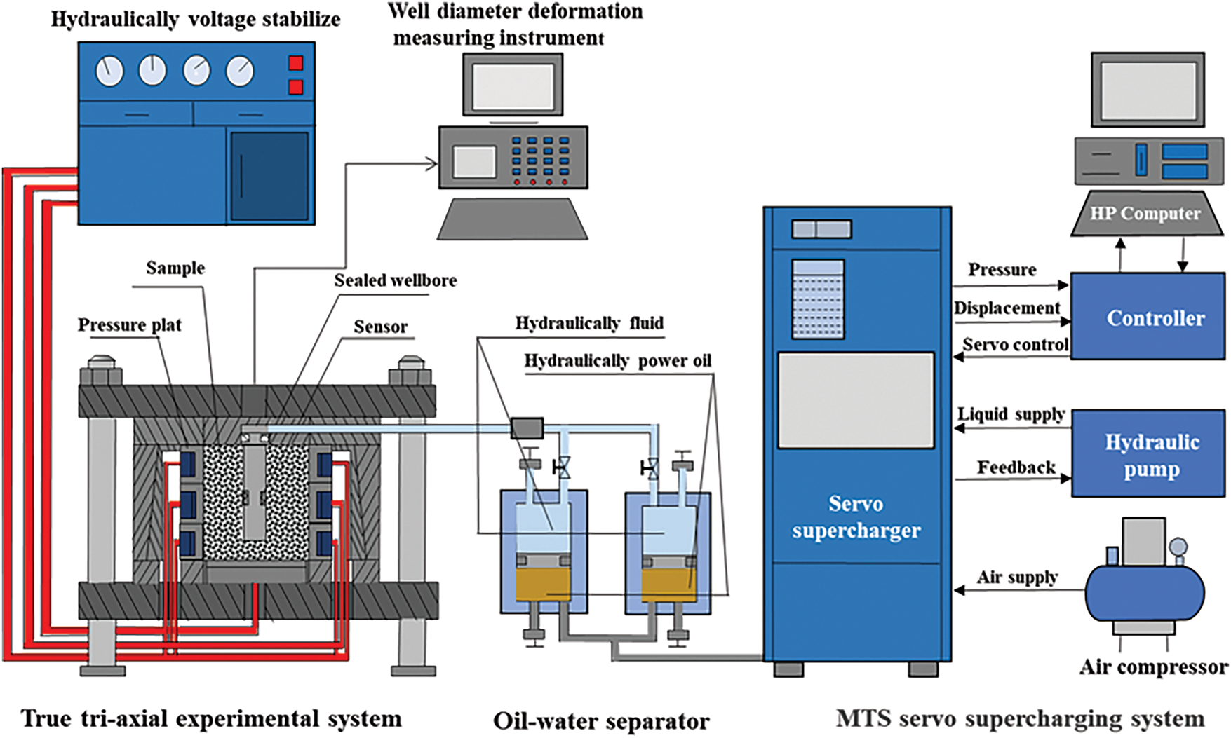
Figure 1: True triaxial hydraulic fracturing physical simulation experiment device
2.1.1 Rock Mechanics Parameters
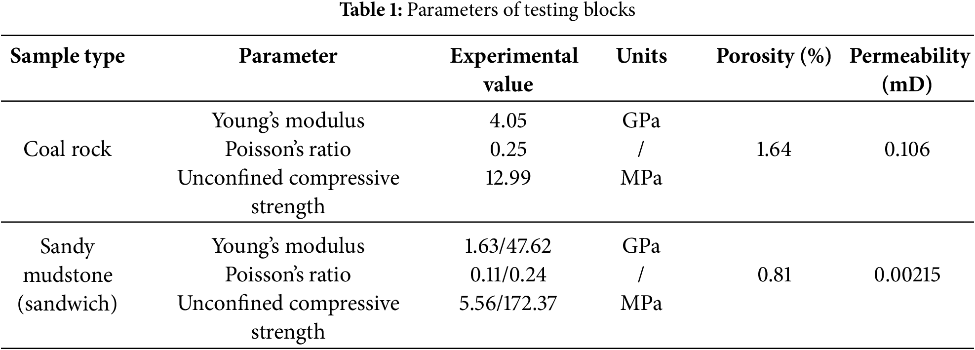
The coal rock and gangue samples used for the test were collected from the Shenfu-Dongsheng coalfield in the Yushen mining area, northern Shaanxi Province. The sandy mudstone samples of the outcrop near the mining area are used as the adjacent interlayers of the coal seam. The rock mechanics parameters of the coal rock and the interlayer rock are shown in Table 1.
2.1.2 XRD Whole-Rock Mineral Composition Analysis
The mineral composition of reservoir rock is related to rock strength, brittleness and reservoir sensitivity, which will affect the complexity of fractures during fracturing. It is necessary to carry out whole rock mineral composition analysis experiments on collected downhole coal and rock cores, and the corresponding XRD experimental process is presented in Fig. 2.
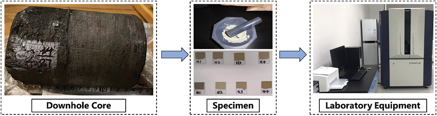
Figure 2: XRD whole rock mineral composition analysis experimental process
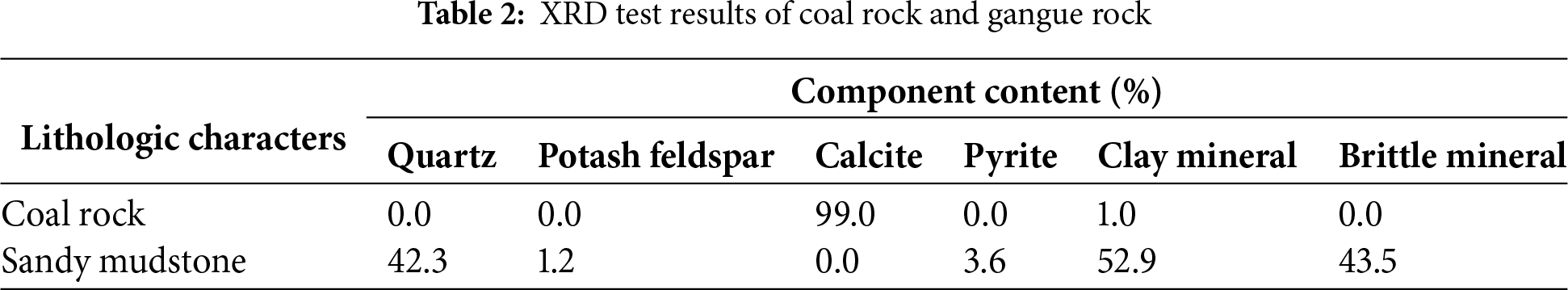
The parting layer is sandy mudstone, which is mainly composed of brittle minerals such as quartz and feldspar and clay minerals. The average brittle mineral content is 37.78%. The coal rock is mainly composed of calcite and clay minerals, and does not contain brittle minerals. It has certain plasticity and is prone to plastic deformation during fracturing. XRD results are shown in Table 2.
2.1.3 Sample Preparation and Experimental Scheme
The specimens were prepared according to the following steps: (1) The irregular coal rock and sandy mudstone outcrop were cut into cuboids by NC wire cutting machine, using high-strength epoxy resin glue to splice the coal rock rock plate and the sandy mudstone rock plate to simulate the true triaxial specimen of coal rock in the gangue interaction coal seam. (2) A 160 mm deep sinkhole was drilled on the narrow surface of the cuboid using a hollow drill bit with a diameter of 20 mm and a length of 200 mm to simulate the wellbore. (3) Consolidate the simulated wellbore with high-strength epoxy resin glue in the wellbore; Fig. 3 shows the sample preparation process and finished sample.
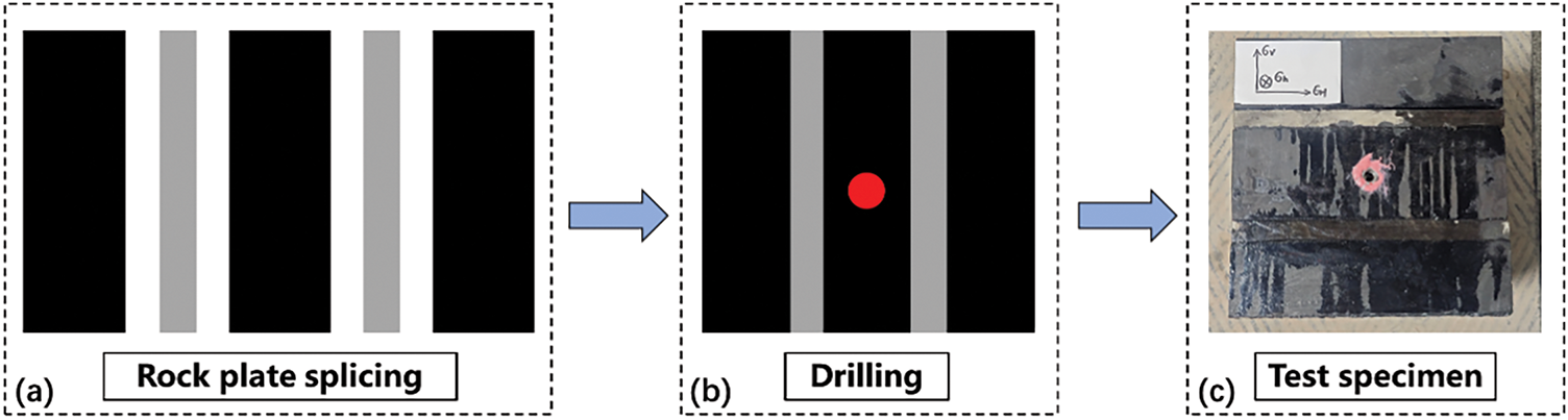
Figure 3: Coal sample preparation process (a) Rock plate preparation; (b) Rock plate splicing and drilling; (c) samples making
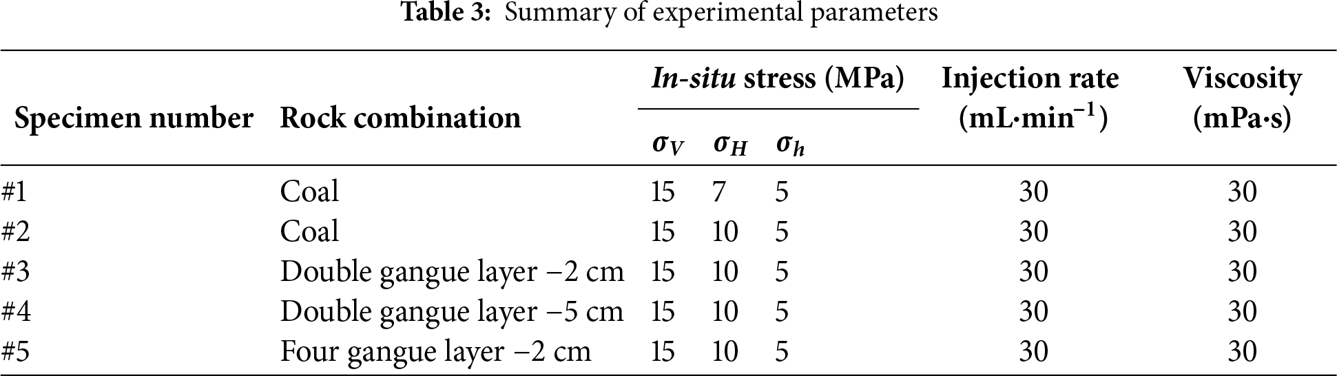
In order to explore the influence of different geological-engineering parameters on the initiation and propagation of artificial fractures in multi-gangue interactive coal seams, different stress and pumping parameters were set up in the indoor true triaxial hydraulic fracturing experiment, in which
The experimental process is divided into three stages: preparation before the experiment, beginning of the experiment and end of the experiment and data collation. Before the experiment, the core needs to be observed, and the fracturing fluid needs to be prepared. Then, the coal rock core samples wrapped with concrete were placed in the true triaxial hydraulic fracturing physical simulation device, and the stress loading device and pump injection pipeline were installed. Through the remote control system, the three-dimensional in-situ stress is set in the control room. After the stress loading is completed, the pumping program is set up. According to the predetermined experimental scheme, the corresponding fracturing fluid displacement is set. Before the whole stress loading and pumping program starts, the data acquisition system is started to record the pump pressure and stress changes. During the fracturing process, when the pump pressure curve reaches the fracture pressure, it shows that the core is broken, and the injection and data recording of the fracturing fluid are stopped. After the pressure relief device completely unloads the pipeline and the three-dimensional ground stress, the experiment ends. The samples in the experimental device were taken out, and the fracture morphology after pressing was characterized by the distribution of phosphors on the fracture surface after opening the samples.
In this experiment, the propagation law of hydraulic fractures in multi-gangue interactive coal seams in Linxing-Shenfu area was studied by true triaxial hydraulic fracturing physical simulation system. The results show that the propagation of hydraulic fracturing fractures in deep coal reservoirs in Linxing-Shenfu is significantly affected by in-situ stress and the properties of the gangue layer. In-situ stress dominates the direction of fracture propagation, and the gangue layer affects the longitudinal extension distance of artificial fractures in horizontal wells in deep coal seams.
2.2.1 Effect of Stress Difference on Fracture Propagation of Coal Rock
Under the condition of stress difference of 2 MPa, displacement of 30 mL/min and fracturing fluid viscosity of 30 mPa·s, hydraulic fracturing forms a complex fracture network system dominated by vertical main fracture (transverse fracture), as shown in Fig. 4. The vertical main fracture expands along the direction of the maximum horizontal principal stress, accompanied by interlayer fracture communication, which indicates that the fracturing fluid is easy to infiltrate in the coal rock cleat weak surface, forming a complex fracture morphology of vertical main fracture + cleat weak surface. The non-uniform distribution of cleats in coal rock causes the asymmetric distribution of fracture morphology near the artificial wellbore.
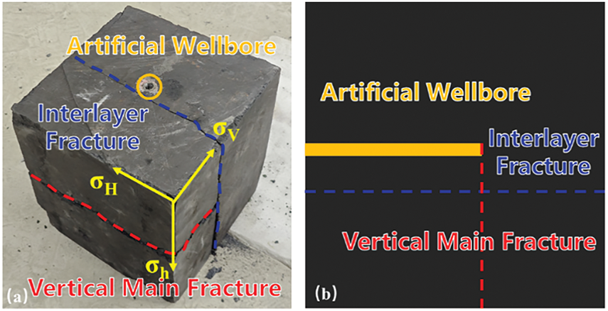
Figure 4: The fracture morphology characteristics of pure coal rock under stress difference of 2 Mpa (a) sam-ples making (b) legend illustration
Under the condition of stress difference of 5 MPa, displacement of 30 mL/min and fracturing fluid viscosity of 30 mPa·s, the hydraulic fracturing of deep coal rock forms a fracture propagation mode dominated by vertical main fracture (transverse fracture), as shown in Fig. 5. The fracture extends along the direction of maximum principal stress, showing obvious characteristics of single dominant fracture. Compared with the complex fracture network formed under the condition of low stress difference (2 MPa), the high stress difference significantly enhances the tendency of the fracture to extend along the direction of the horizontal maximum principal stress, reduces the fluid along the weak surface effect caused by the existence of cleats in coal rock, inhibits the development of interlayer fractures, and makes the fracture morphology tend to be simplified. This indicates that the increase of the stress difference will enhance the control of the in-situ stress field on the fracture extension path and reduce the influence of the natural weak plane on the fracture propagation. In addition, under the condition of high stress difference, the fracture surface opens perpendicular to the direction of the minimum horizontal principal stress, indicating that the stress difference plays a leading role in the evolution of fracture morphology. The synergistic effect of the high viscosity (30 mPa·s) of the fracturing fluid and the high stress difference suppresses the fracture branch and makes the fracture extension direction more concentrated.
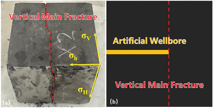
Figure 5: The fracture morphology characteristics of pure coal rock under stress difference of 5 Mpa (a) samples making (b) legend illustration
Under the condition of displacement of 30 mL/min and fracturing fluid viscosity of 30 mPa·s, the stress difference has a significant effect on the fracture pressure and fracture morphology of coal rock hydraulic fracturing. When the stress difference is 2 MPa (Fig. 6a,b), the fracture pressures of 1 # and 2 # specimens are 18 and 11.8 MPa, respectively, showing a large difference. Under the condition of high stress difference, the microfractures, such as cleats and joints in coal rock are gradually compacted by stress extrusion, and the internal structure of coal rock is more compact. Under the condition of low stress difference, the fracture morphology (Fig. 6c) is more complex, and the vertical main fracture (transverse fracture) and interlayer fractures are synergistically developed, which indicates that the natural weak plane has a significant control effect on the fracture propagation path under the condition of low stress difference. When the stress difference increases to 5 MPa (Fig. 6c), the fracture pressure tends to be stable, the fracture morphology changes into an extension mode dominated by a single vertical main fracture, and the development of interlayer fractures is obviously weakened. This phenomenon reveals the strong control effect of in-situ stress field on fracture propagation under high stress difference conditions, and effectively inhibits the influence of natural fractures, such as cleats on fracture propagation. The experimental results show that increasing the stress difference promotes the transformation of fracture morphology from complex network to single main fracture.
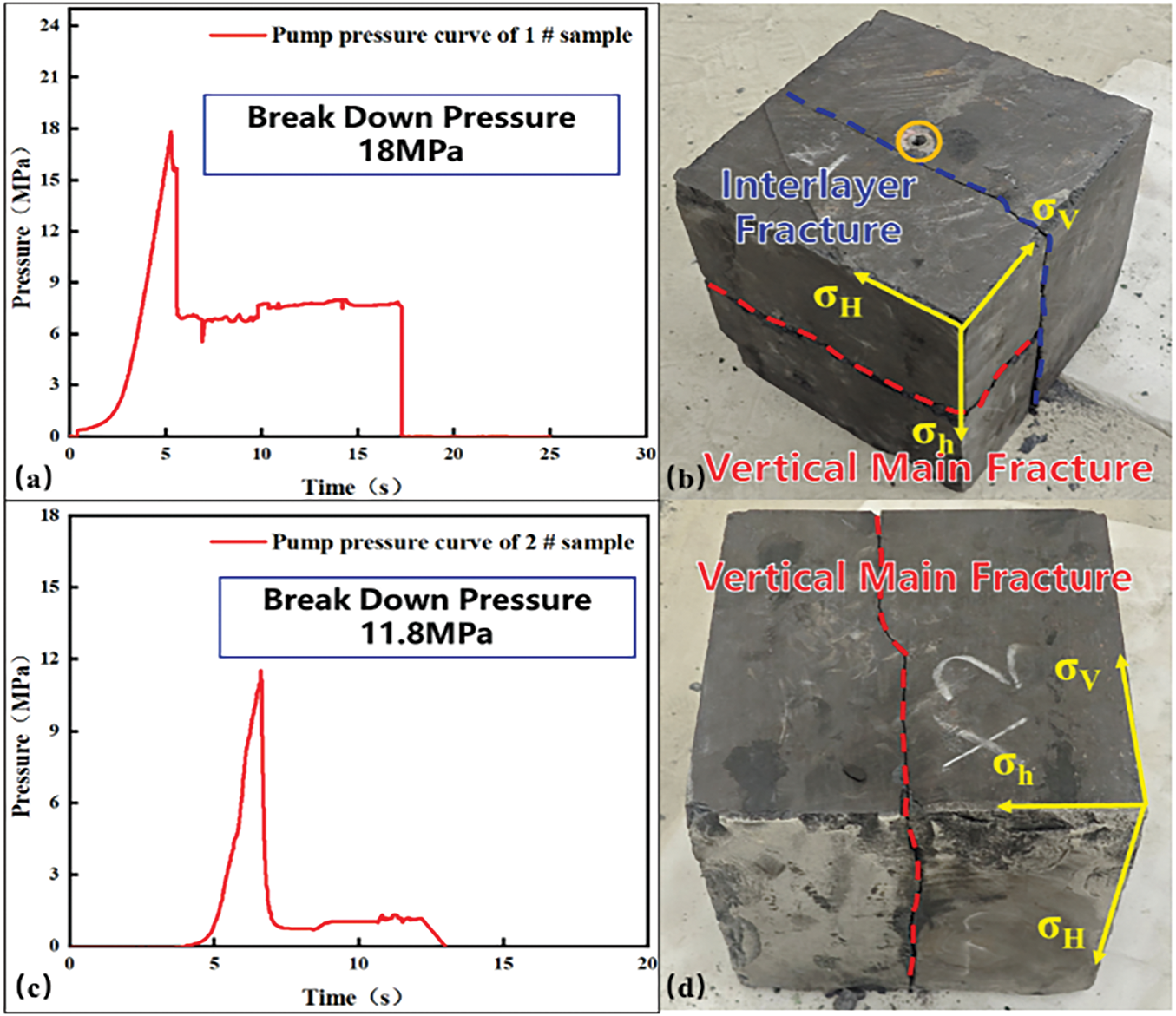
Figure 6: Fracture morphology characteristics of coal rock with different stress difference (a) the fracture pressure of 1 # specimen (b) 1 # specimen (c) the fracture pressure of 2 # specimen (d) 2 # specimen
2.2.2 The Influence of Interlayer Thickness on Fracture Penetration
Under the condition of displacement of 30 mL/min and fracturing fluid viscosity of 30 mPa·s, two gangue layers with thickness of 2 cm are set up. The fracture morphology shows that the gangue layer significantly affects the fracture propagation behavior of deep coal rock hydraulic fracturing, as shown in Fig. 7. The vertical main fracture (transverse fracture) extends along the direction of the maximum principal stress in the coal-rock matrix. However, due to the influence of the gangue layer, the fracture occurs after the vertical expansion to the bottom gangue layer, and the local interlayer seam is formed at the interface between the gangue layer and the coal seam. The gangue layer (thickness 2 cm) has high elastic modulus and greater mechanical strength, which inhibits the vertical penetration ability of the fracture, promotes the fracturing fluid to flow preferentially along the interface between the gangue layer and the coal rock, and the complex fracture network of vertical main fracture + interlayer fracture. The fracture morphology near the artificial wellbore shows an asymmetric distribution, indicating that the disturbance of the gangue layer to the near-well stress field aggravates the deflection of the fracture initiation direction. The experimental data reveal that although the thin layer of dirt band (≤2 cm) does not completely block the vertical expansion of the fracture, its interface effect significantly enhances the spatial complexity of the fracture system.
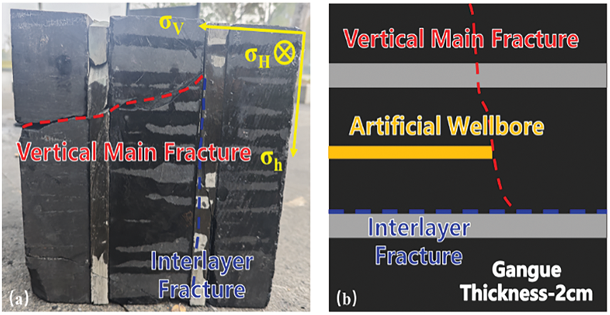
Figure 7: The characteristics of hydraulic fracture propagation when the thickness of gangue layer is 2 cm (a) Hydraulic fractures in two gangue layer samples with a thickness of 2 cm (b) Legend of two gangue layer samples with a thickness of 2 cm
Two gangue layer samples with a thickness of 5 cm extend vertically along the direction of the maximum principal stress. Due to the influence of the thick gangue layer, the vertical expansion of the fracture is hindered. The fracturing fluid preferentially flows along the weak surface of the gangue layer and the coal-rock interface, as shown in Fig. 8, forming a multi-stage interlayer fracture and a complex fracture network around the gangue body. The increase of the thickness of the parting layer strengthens the hindrance to the propagation of the hydraulic fracture, which leads to the significant turning of the fracture along the layer interface at the interface and inhibits the longitudinal penetration ability of the single main fracture. The experimental results further show that when the thickness of the gangue layer increases to 5 cm, the blocking effect on the fracture is stronger, and the fracture system changes from vertical expansion to horizontal interlayer expansion.
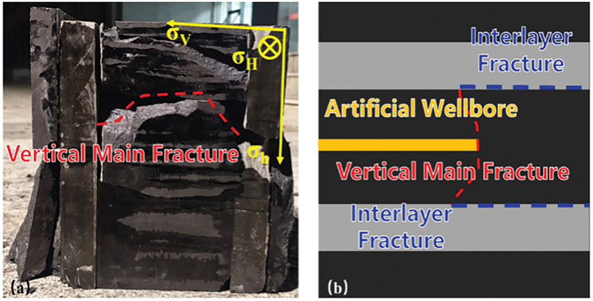
Figure 8: The characteristics of hydraulic fracture propagation when the thickness of gangue layer is 5 cm (a) Hydraulic fractures in two gangue layer samples with a thickness of 5 cm (b) Legend of two gangue layer samples with a thickness of 5 cm
Under the condition of displacement of 30 mL/min and fracturing fluid viscosity of 30 mPa·s, the thickness of the parting layer has a significant effect on the fracture propagation mode of deep coal rock hydraulic fracturing. The fracture pressures of 3 # and 4 # samples are 13 and 13.5 MPa, respectively, indicating that the thickness of the gangue layer does not significantly affect the fracture pressure when the coal seam fractures. The fracture morphology is mainly vertical main fracture (transverse fracture). With the local development of interlayer fractures, it reflects that the thin parting layer has an effect on the fracture penetration, but it fails to completely block the vertical expansion of the fracture. When the thickness of the gangue layer increases to 5 cm (Fig. 9c,d), the fracture pressure remains stable but the fracture morphology changes significantly. The hydraulic fracture of the thick gangue layer is difficult to propagate through the layer, and the vertical penetration ability of the fracture is inhibited, forming a complex fracture network of ‘cross-cutting fracture + interlayer fracture’. This phenomenon shows that the increase of the thickness of the gangue layer promotes the evolution of the fracture system from the vertical dominant type to the lateral expansion type by enhancing the energy loss in the process of fracture propagation through the layer.
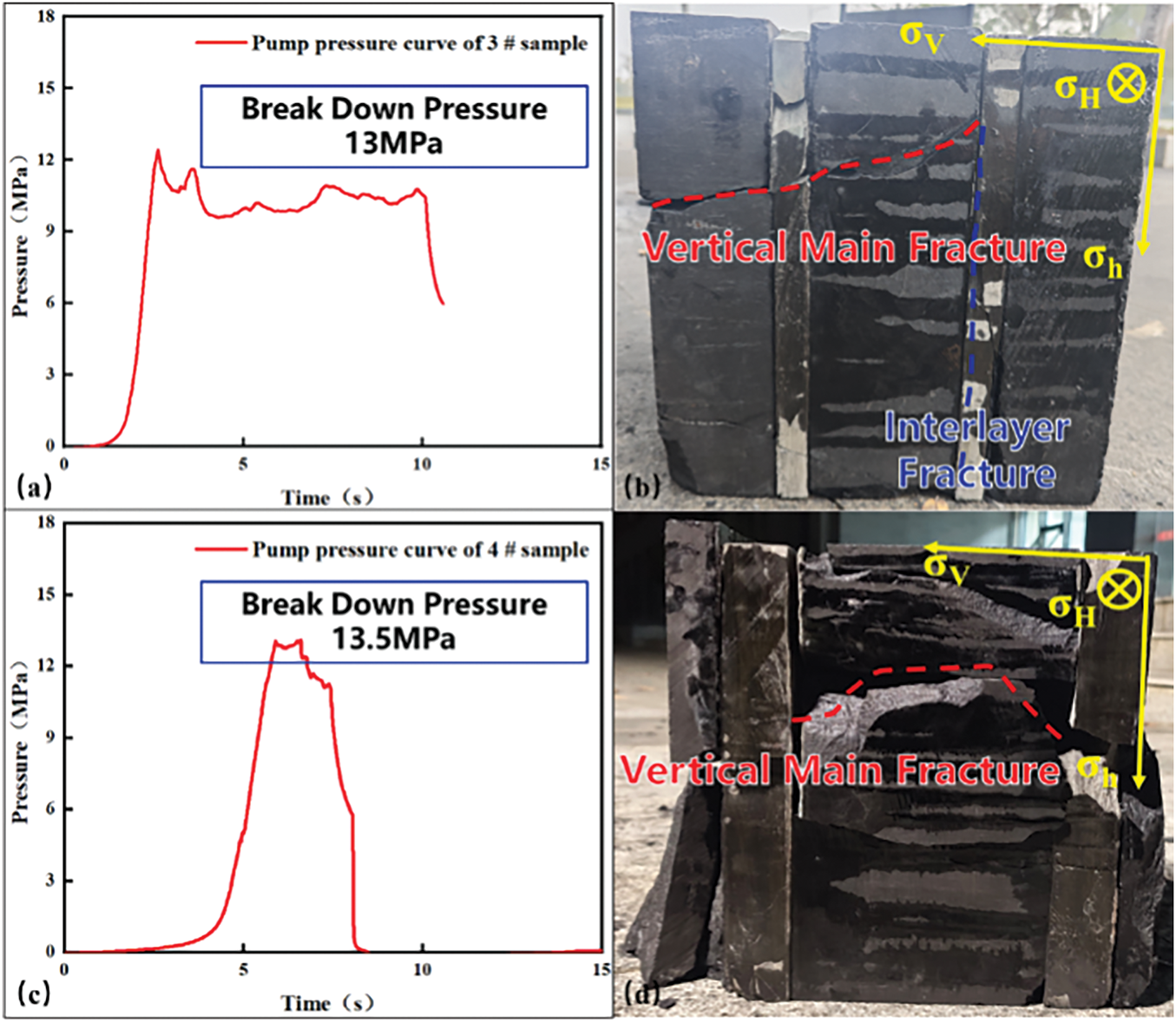
Figure 9: Hydraulic fracture propagation characteristics of different gangue layer thickness (a) the fracture pressure of 3 # specimen (b) 3 # specimen (c) the fracture pressure of 4 # specimen (d) 4 # specimen
2.2.3 The Influence of the Number of Interlayers on the Fracture Penetration
Under the condition of displacement of 30 mL/min and fracturing fluid viscosity of 30 mPa·s, the complexity of fracture system in the process of hydraulic fracturing of deep coal rock is significantly enhanced by setting double gangue layer coal rock samples, as shown in Fig. 10. When the vertical main fracture (transverse fracture) extends along the direction of the maximum principal stress, it is affected by the gangue layer in the extension direction. The fractures turn at a small angle at the interface, and then extend through the sample to the rock boundary, forming a multi-level interlaced fracture network associated with interlayer fractures. The double gangue layer promotes the fracturing fluid to flow preferentially along the gangue-coal rock contact surface, resulting in limited vertical penetration ability of the fracture.
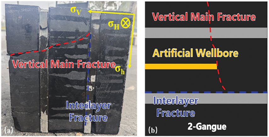
Figure 10: Fracture propagation characteristics of coal rock in double gangue layer (a) samples making (b) legend illustration
Under the condition of displacement of 30 mL/min and fracturing fluid viscosity of 30 mPa·s, four gangue layers with a thickness of 2 cm were set. When the vertical main fracture (transverse fracture) expands along the direction of the maximum horizontal principal stress, affected by multiple gangue layers (4 layers, as shown in Fig. 11), the fracture turns several times at the interface between gangue and coal rock, forming a fracture network structure with vertical fracture as the main and interlayer fracture interweaving. The continuous expansion of the vertical main fracture is blocked due to the increase of the number of the gangue layer, and the multi-level interlayer fractures are induced to extend along the direction of the minimum horizontal principal stress. After the fracture initiates, it penetrates the adjacent gangue layer but cannot penetrate the rock sample along the vertical main fracture direction, and the fracture percolation effect at the middle interface of the multi-gangue layer sample is significant. Compared with the condition of few-layer parting, the four-layer parting has a stronger inhibitory effect on the fracture propagation through the layer. By communicating the multi-layer interface, the fracture system evolves to the three-dimensional network structure, which reveals the complexity of fracture propagation in the multi-layer parting coal reservoir.
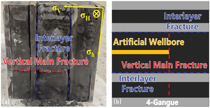
Figure 11: Fracture propagation characteristics of coal rock in four parting layers (a) samples making (b) legend illustration
Under the condition of displacement of 30 mL/min and fracturing fluid viscosity of 30 mPa·s, the number of gangue layers has a significant effect on the propagation ability of hydraulic fracturing fractures in deep coal and rock. The fracture pressure of 3# and 5# samples is 12.5 and 23.5 MPa, respectively, indicating that the heterogeneity of the number of gangue layers has a key influence on the fracture pressure. This is because when the hydraulic fracture penetrates the adjacent gangue layer to continue the longitudinal expansion process, the fracture propagation resistance of the boundary gangue layer increases, and more hydraulic energy is required. The fracture morphology is dominated by the vertical main fracture (transverse fracture), accompanied by the development of local interlayer fractures, which reflects that the fracturing fluid seepage at the interface of the gangue layer does not completely block the vertical continuous expansion of the fracture. When the number of gangue layers increases to 4 (Fig. 12c,d), the fracture pressure increases significantly to 23.5 MPa, and the fracture system presents a three-dimensional network structure intertwined with the vertical main fracture and the dense interlayer fracture, indicating that the multi-gangue layer conditions force the fracture to bifurcate and turn frequently in the vertical expansion, the continuity of the main fracture is destroyed, and the fracturing fluid preferentially forms a transverse channeling channel along the multi-level weak surface. This law shows that the increase in the number of gangue layers significantly increases the fracture pressure by strengthening the heterogeneity of the reservoir, and the fracture system evolves from “vertical penetration type ‘to’ multi-branch expansion type”.
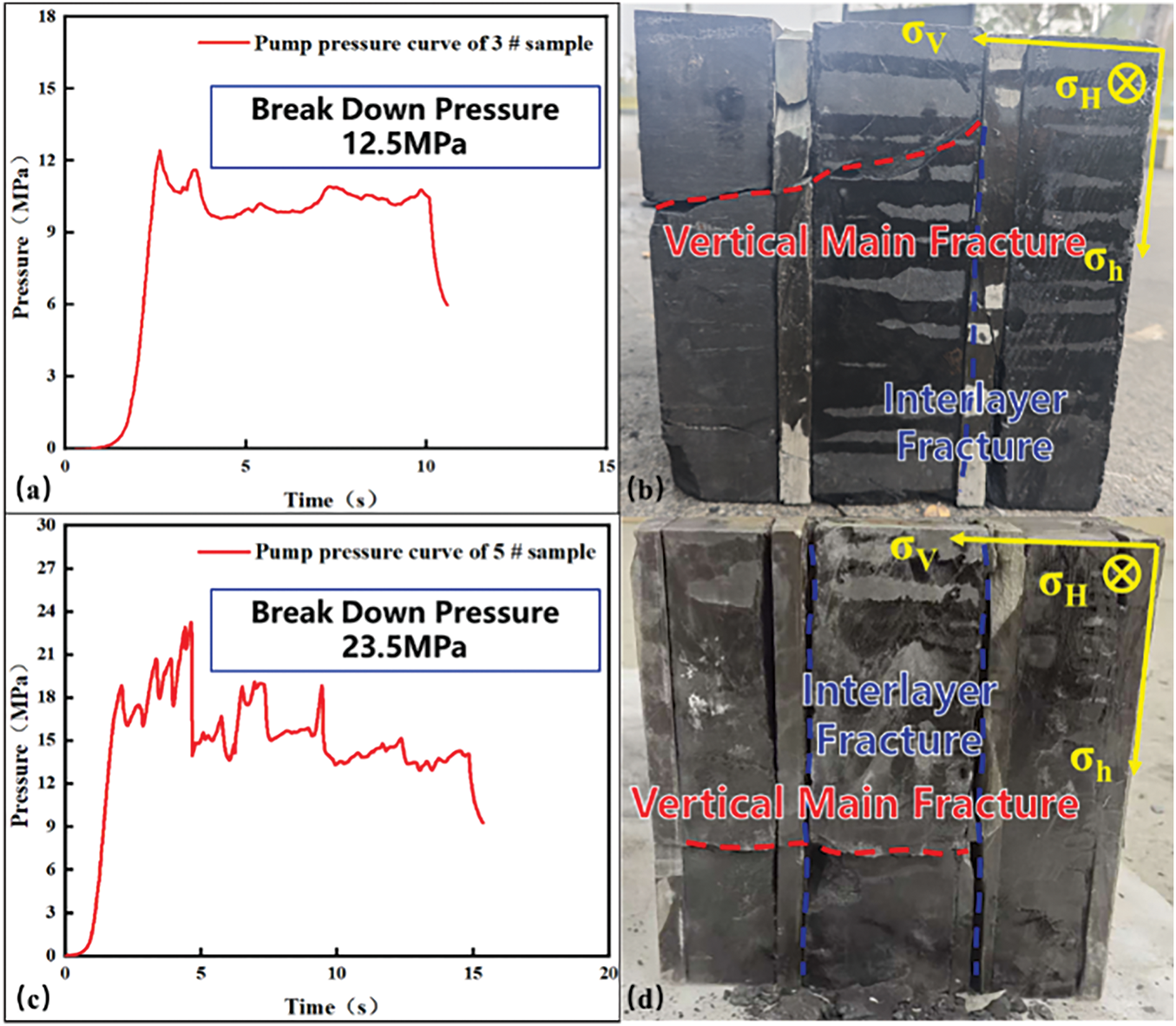
Figure 12: The fracture propagation characteristics of coal rock with different number of gangue layers (a) the fracture pressure of 3 # specimen (b) 3 # specimen (c) the fracture pressure of 5 # specimen (d) 5 # specimen
2.2.4 Propagation Law of Multi-Interlayer Coal-Rock Fracture Crossing Layer
The thickness of the parting layer (the difference between Fig. 13a,b) hinders the vertical extension of the main fracture. The thin gangue layer (Fig. 13a) is easy to be broken through by the fracturing fluid due to its low tensile strength and weak fracture toughness, forming a penetrating vertical main fracture (transverse fracture); however, due to the significant stress concentration effect, the fractures in the thick parting layer (Fig. 13b) tend to expand along the weak interlayer surface, forming interlayer fractures or local steering, resulting in a decrease in the vertical penetrating ability.
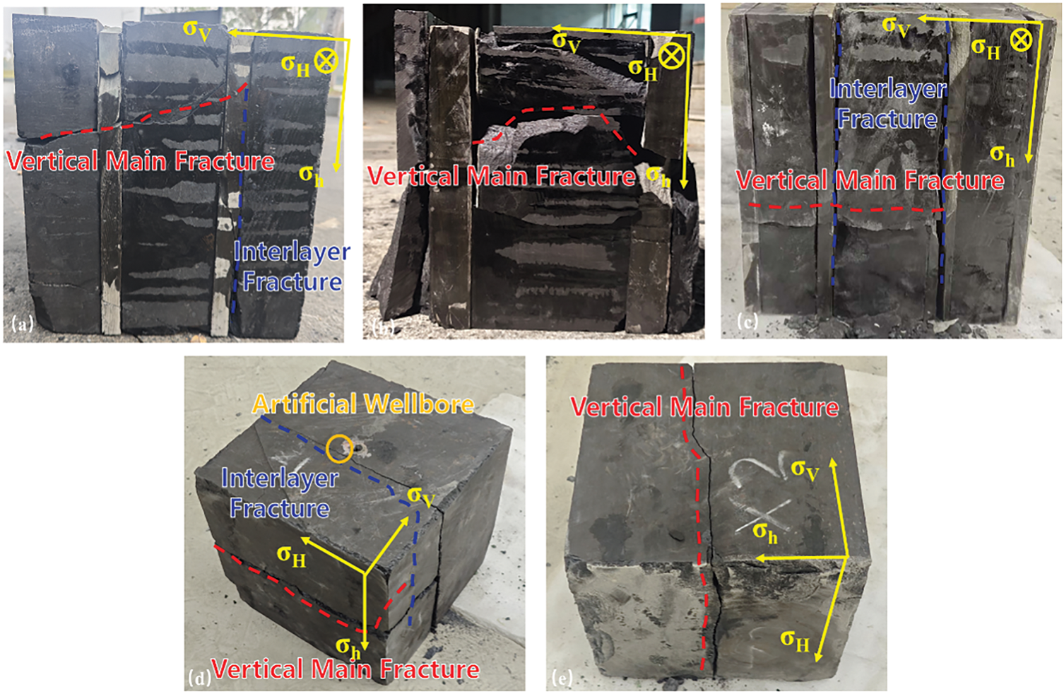
Figure 13: Fracture propagation law of multi-gangue interactive coal seam (a) the crack propagation law of the thin gangue layer (b) the crack propagation law of the thick parting layer (c) the crack propagation law of the multi-gangue layer (d) crack propagation law under low stress difference (e) crack propagation law under high stress difference
The multi-gangue layer (Fig. 13c) increases the density of the interlayer interface, induces the multi-stage turning of the fracture and connects to the interface between the multi-gangue and the coal seam. The behavior of fracture penetrating and blasting leads to the increase of hydraulic energy dissipation, forming a ‘segmented’ fracture network. At this time, the cementation strength of the layer interface and the size of the hydraulic energy jointly determine the fracture morphology.
The stress difference (the difference between Fig. 13d,e) affects the complexity of the fracture. Under low stress difference (Fig. 13d), fractures tend to propagate along the direction of minimum horizontal principal stress, so it is easy to induce multi-branch interlayer fractures while forming vertical main fractures. Under the condition of high stress difference (Fig. 13e), fractures preferentially extend along the direction of maximum principal stress, forming a single main fracture and inhibiting interlayer communication.
Compared with the traditional sand-mud interbedded fracture propagation mode [22], under the condition of low stress difference, sand-mud interbedded fractures are easy to form ‘T’-shaped fractures and cannot propagate through the layer, which is consistent with the fracture propagation law of coal-rock hydraulic fracturing in this paper. However, due to its lower brittleness, the internal structure of the rock is more loose, and the cleat structure is developed in the coal-rock, resulting in more microfractures at the fracture tip during the coal-rock interbedded fracturing process, and the fracture morphology is more complex.
The expansion of hydraulic fractures in the gangue-interacting coal seam is controlled by the stress-gangue interaction mode. The lithology of the gangue layer is significantly different from the mechanical properties of coal and rock, and its thickness and quantity regulate the balance of fracture layer-turning by changing the local stress field and energy distribution. The stress difference determines the path selection and network complexity of fracture propagation through the redistribution of the macroscopic stress field. The optimization of fracturing design needs to comprehensively consider the mechanical parameters of the parting layer, the distribution of the parting layer and the in-situ stress, so as to realize the vertical high-efficiency layer crossing and lateral full expansion of the fracture.
3 Propagation Mechanism of Multi-Interlayer Coal-Rock Fracture Crossing Layer
The three-dimensional discrete lattice method (3D Lattice Method) is a simplified discrete element numerical model based on particle structure [24,25]. In this paper, based on the three-dimensional discrete lattice method, combined with logging data and the study of rock mechanics parameters of coal rock and gangue rock in the reservoir section, a three-dimensional numerical model of 30 × 30 × 30 m3 is established as shown in the figure. The propagation law of hydraulic fracturing fractures in coal-rock reservoirs with multiple interlayers is studied. In order to truly restore the rock properties of the reservoir, the basic physical parameters of the model are shown in Table 1. On the basis of the basic rock mechanics parameters, in order to study whether the fractures can extend through the layers under different geomechanical conditions, this paper sets different stress differences, interlayer thickness and interlayer number in the numerical model. The simulation results are shown in Table 4.
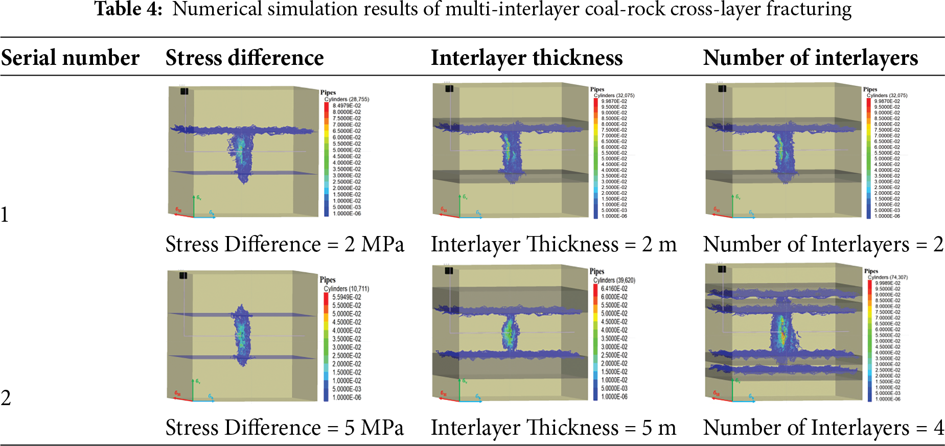
As shown in Table 4, the numerical simulation results of multi-interlayer coal-rock cross-layer fracturing are established based on the logging data and rock mechanics parameters of deep coal-rock reservoirs in Linxing-Shenfu. From the change of stress difference, under the condition of low stress difference (2 MPa), the hydraulic energy decays rapidly in the coal seam, and the fracture is difficult to break through the interlayer stress blockade, and the fracture propagation is limited to the inside of the coal seam. Under the condition of high stress difference (5 MPa), the trend of hydraulic fracture propagation along the horizontal maximum principal stress increases, which can penetrate the adjacent layers and form a vertically connected multi-layer fracture network. From the perspective of interlayer thickness, when the interlayer thickness is 2 m, the fracture can vertically penetrate the interlayer and connect the upper and lower layers. However, as the thickness increases to 5 m, the energy of the fracture in the interlayer decays seriously, the propagation path is blocked, and it is difficult to continue to extend vertically, showing the inhibition of the thick interlayer on the fracture propagation. As the number of interlayers increases from 2 to 4 layers, a large amount of energy loss is generated at the interface of each layer during the process of fracture penetration, and the fracture propagation path is complex. Although the fracture can penetrate the adjacent interlayer, it cannot be further extended to the upper and lower boundary layers, forming a limited communication range.
The fracture propagation of the deep coal reservoir in Linxing-Shenfu area is significantly affected by stress difference. The fracture morphology of pure coal rock sample is more complex when the stress difference is less than 2 MPa. With the increase of stress difference, the trend of hydraulic fracture extending along the direction of horizontal maximum principal stress increases after fracture initiation, which is dominated by single transverse fracture, and the branch fracture decreases significantly.
The penetrating ability of hydraulic fractures in multi-interlayer interactive coal seams is affected by the thickness and number of dirt band. The hydraulic fracture is easy to penetrate the thin interlayer. When the thickness of the interlayer increases, the attenuation of hydraulic energy in the process of fracture penetration is greater, and the fracture connects to the interface between the coal seam and the gangue layer, but the propagation distance is limited. When the number of gangue layers is small (2 layers in this paper), the energy consumption of hydraulic fractures is less after passing through the layers. The fractures can penetrate the adjacent interlayers, but cannot be further extended to the upper and lower boundary layers, and the reservoir reconstruction volume is limited.
Acknowledgement: Not applicable.
Funding Statement: This work was supported by National Key Laboratory of Petroleum Resources and Engineering, China University of Petroleum, Beijing (No. PRE/open-2307).
Author Contributions: Study conception and design: Qingwei Zeng, Xuesong Xing, Li Wang; data collection: Jingyu Zi; analysis and interpretation of results: Heng Wen, Ying Zhu; draft manuscript preparation: Yanan Hou. All authors reviewed the results and approved the final version of the manuscript.
Availability of Data and Materials: Data will be made available on request.
Ethics Approval: Not applicable.
Conflicts of Interest: The authors declare no conflicts of interest to report regarding the present study.
References
1. Geng M, Chen H, Chen Y, Zeng L, Chen S, Jiang X. Methods andresults of the fourth round national CBM resources evaluation. Coal Sci Technol. 2018;46(6):64–8. doi:10.13199/j.cnki.cst.2018.06.011. [Google Scholar] [CrossRef]
2. Zhang D, Zhu J, Zhao X, Gao Y, Geng M, Chen G, et al. Dynamic assessment of coalbed methane resources and availability in China. J China Coal Soc. 2018;43(6):1598–604. doi:10.13225/j.cnki.jccs.2018.4035. [Google Scholar] [CrossRef]
3. Ren H, Meng Z, Wang X. Pore structure and porosity-permeability evolution characteristics of coal/rocks under the action of high-viscosity slickwater. Energy Fuels. 2025;39(11):5279–94. doi:10.1021/acs.energyfuels.4c05938. [Google Scholar] [CrossRef]
4. Ahamed MAA, Perera S, Elsworth D. Effective application of proppants during the hydraulic fracturing of coal seam gas reservoirs: implications from laboratory testings of propped and unpropped coal fractures. Fuel. 2021;304(2):121394. doi:10.1016/j.fuel.2021.121394. [Google Scholar] [CrossRef]
5. Longinos SN, Dillinger A, Wang L, Hazlett R. Uniaxial compressive strength (UCS) and SEM study of liquid nitrogen for waterless hydraulic fracturing in coalbed methane reservoirs of Karaganda Basin in Kazakhstan. Gas Sci Eng. 2023;115(1):204998. doi:10.1016/j.jgsce.2023.204998. [Google Scholar] [CrossRef]
6. Longinos SN, Abbas AH, Bolatov A, Skrzypacz P, Hazlett R. Application of image processing in evaluation of hydraulic fracturing with liquid nitrogen: a case study of coal samples from Karaganda Basin. Appl Sci. 2023;13(13):7861. doi:10.3390/app13137861. [Google Scholar] [CrossRef]
7. Warpinski NR, Kramm RC, Heinze JR, Waltman CK. Comparison of singleand dual-array microseismic mapping techniques in the Barnett Shale. In: Proceedings of the SPE Annual Technical Conference and Exhibition; 2024 Sep 23–25; New Orleans, LA, USA. Houston, TX, USA: Society of Petroleum Engineers; 2005. [Google Scholar]
8. Beugelsdijk LJL, de Pater CJ, Sato K. Experimental hydraulic fracture propagation in a multi-fractured medium. In: Proceedings of the SPE Asia Pacific Conference on Integrated Modelling for Asset Management; 2000 Apr 25–26; Yokohama, Japan. Yokohama, Japan: Society of Petroleum Engineers; 2000. p. 1–8. [Google Scholar]
9. Chen Z, Jeffrey RG, Zhang X, Kear J. Finite-element simulation of a hydraulic fracture interacting with a natural fracture. SPE J. 2017;22(1):219–34. doi:10.2118/176970-pa. [Google Scholar] [CrossRef]
10. Karadkar P, Harbi B, Malik A, Alsakkaf M, Khan S. CO2 Foamed fracturing fluids for high temperature hydraulic fracturing. In: Proceedings of the SPE Middle East Oil and Gas Show and Conference; 2023 Feb 19–21; Manama, Bahrain. Dallas, TX, USA: SPE; 2023. [Google Scholar]
11. Yang F, Li B, Wang K, Wen H, Yang R, Huang Z. Extreme massive hydraulic fracturing in deep coalbed methane horizontal wells: a case study of Linxing Block, eastern Ordos Basin, NW China. Pet Explor Dev. 2024;51(2):440–52. doi:10.1016/s1876-3804(24)60035-2. [Google Scholar] [CrossRef]
12. Tan P, Jin Y, Hou B, Han K, Zhou Y, Meng S. Experimental investigation on fracture initiation and non-planar propagation of hydraulic fractures in coal seams. Pet Explor Dev. 2017;44(3):470–6. doi:10.11698/PED.2017.03.14. [Google Scholar] [CrossRef]
13. Dahi-Taleghani A, Olson JE. Numerical modeling of multistranded-hydraulic fracture propagation: accounting for the interaction between induced and natural fractures. SPE J. 2011;16(3):575–81. doi:10.2118/124884-pa. [Google Scholar] [CrossRef]
14. Sharma A, Chen H, Teufel L. Flow-induced stress distribution in a multi-rate and multi-well reservoir. In: Proceedings of the SPE Rocky Mountain Petroleum Technology Conference/Low-Permeability Reservoirs Symposium; 1998 Apr 5–8; Denver, CO, USA. [Google Scholar]
15. Blanton T. An experimental study of interaction between hydraulically induced and pre-existing fractures. In: Proceedings of the SPE Unconventional Gas Recovery Symposium; 1982 May 16–18; Pittsburgh, PA, USA. Pittsburgh, PA, USA: Society of Petroleum Engineers; 1982. p. 559–71. [Google Scholar]
16. Wu K, Olson JE. Mechanics analysis of interaction between hydraulic and natural fractures in shale reservoirs. In: Proceedings of the Unconventional Resources Technology Conference; 2014 Aug 25–27; Denver, CO, USA. Denver, CO, USA: Society of Exploration Geophysicists, American Association of Petroleum Geologists, Society of Petroleum Engineers; 2014. p. 1824–41. [Google Scholar]
17. Cooke ML, Underwood CA. Fracture termination and step-over at bedding interfaces due to frictional slip and interface opening. J Struct Geol. 2001;23(2):223–38. doi:10.1016/s0191-8141(00)00092-4. [Google Scholar] [CrossRef]
18. Taleghani AD, Olsonj E. How natural fractures could affect hydraulic-fracture geometry. SPE J. 2014;19(1):161–71. doi:10.2118/167608-pa. [Google Scholar] [CrossRef]
19. Mcclure MW, Horne RN. Discrete fracture network modeling of hydraulic stimulation: coupling flow and geomechanics. Dordrecht, The Netherlands: Springer Science & Business Media; 2013. [Google Scholar]
20. Zhang X, Jeffrey RG. The role of friction and secondary flaws on dellection and re-initiation of hydraulic fractures at orthogonal pre-existing fractures. Geophys J Int. 2006;166(3):1454–65. doi:10.1111/j.1365-246x.2006.03062.x. [Google Scholar] [CrossRef]
21. Xie J, Hou B, He M, Liu X, Wei J. Fracture-controlled fracturing mechanism and penetration discrimination criteria for thin sand-mud interbedded reservoirs in Sulige gas field, Ordos Basin. China Pet Explor Dev. 2024;51(5):1327–39. doi:10.1016/s1876-3804(25)60544-1. [Google Scholar] [CrossRef]
22. Hou B, Chang Z, Fu W, Muhadasi Y, Chen M. Fracture initiation and propagationin a deep shale gas reservoir subject to an alternating-fluid-injectionhydraulic-fracturing treatment. SPE J. 2019;24(4):1839–55. doi:10.2118/195571-pa. [Google Scholar] [CrossRef]
23. Tan P, Chen Z, Fu S, Zhao Q. Experimental investigation on fracture growth for integrated hydraulic fracturing in multiple gas bearing formations. Geoenergy Sci Eng. 2023;231(Pt A):212316. doi:10.1016/j.geoen.2023.212316. [Google Scholar] [CrossRef]
24. Wan X, Rasouli V, Damjanac B, Pu H. Lattice simulation of hydraulic fracture containment in the North Perth Basin. J Pet Sci Eng. 2020;188(5):106904. doi:10.1016/j.petrol.2020.106904. [Google Scholar] [CrossRef]
25. Bakhshi E, Rasouli V, Ghorbani A, Fatehi Marji M, Damjanac B, Wan X, et al. Lattice numerical simulations of lab-scale hydraulic fracture and natural interface interaction. Rock Mech Rock Eng. 2019;52(5):1315–37. doi:10.1007/s00603-018-1671-2. [Google Scholar] [CrossRef]
Cite This Article
 Copyright © 2026 The Author(s). Published by Tech Science Press.
This work is licensed under a Creative Commons Attribution 4.0 International License , which permits unrestricted use, distribution, and reproduction in any medium, provided the original work is properly cited.
 Downloads
 Citation Tools