
 Submit a Paper
 Propose a Special lssue
 Open Access
ARTICLE

AC Fault Characteristic Analysis and Fault Ride-through of Offshore Wind Farms Based on Hybrid DRU-MMC
1 State Grid Zhejiang Electric Power Co., Ltd., Research Institute, DC Technology Research Institute, Hangzhou, 310000, China
2 College of Electrical Engineering, Zhejiang University, Hangzhou, 310027, China
3 Polytechnic Institute, Zhejiang University, Hangzhou, 310027, China
* Corresponding Author: Sihao Fu. Email:
Energy Engineering 2026, 123(2), 7 https://doi.org/10.32604/ee.2025.070934
Received 28 July 2025; Accepted 10 September 2025; Issue published 27 January 2026
 View Full Text
 Download PDF
Abstract
With the rapid development of large-scale offshore wind farms, efficient and reliable power transmission systems are urgently needed. Hybrid high-voltage direct current (HVDC) configurations combining a diode rectifier unit (DRU) and a modular multilevel converter (MMC) have emerged as a promising solution, offering advantages in cost-effectiveness and control capability. However, the uncontrollable nature of the DRU poses significant challenges for system stability under offshore AC fault conditions, particularly due to its inability to provide fault current or voltage support. This paper investigates the offshore AC fault characteristics and fault ride-through (FRT) strategy of a hybrid offshore wind power transmission system based on a diode rectifier unit DRU and MMC. First, the dynamic response of the hybrid system under offshore symmetrical three-phase faults is analyzed. It is demonstrated that due to the unidirectional conduction nature of the DRU, its AC current rapidly drops to zero during faults, and the fault current is solely contributed by the wind turbine generators (WTGs) and wind farm MMC (WFMMC). Based on this analysis, a coordinated FRT strategy is proposed, which combines a segmented current limiting control for the wind-turbine (WT) grid-side converters (GSCs) and a constant AC current control for the WFMMC. The strategy ensures effective voltage support during the fault and prevents MMC current saturation during fault recovery, enabling fast and stable system restoration. Electromagnetic transient simulations in PSCAD/EMTDC verify the feasibility of the proposed fault ride-through strategy.Keywords
Offshore wind power has emerged as a key research field in the global transition to renewable energy due to its abundant wind resources, reduced land use constraints, and declining levelized cost of electricity [1]. A critical technical challenge in offshore wind integration lies in the reliable and efficient transmission of large-scale power from offshore wind farms located far from shore [2]. Currently, two main transmission schemes are widely adopted: the power-frequency AC transmission and high-voltage DC (HVDC) transmission based on modular multilevel converters (MMC) [3]. While the AC transmission approach is highly mature and cost-effective for nearshore projects (typically within 80 km), its feasibility deteriorates rapidly with distance due to the capacitive effects of submarine cables. In contrast, the MMC-HVDC scheme has become the promising solution for medium to long distance offshore wind power delivery, offering superior technical and economic performance despite the high cost and complexity of the offshore converter platforms required [4].
In most commissioned offshore wind projects to date, wind turbines operate in the grid-following mode, behaving as controlled current sources and require an external AC voltage source for synchronization [5]. For the AC transmission scheme, the onshore grid acts as the AC voltage source [6]. For the MMC-HVDC scheme, the offshore MMC station operates in a voltage-frequency (U-f) control mode to establish the offshore AC grid voltage [7]. To further enhance the economic efficiency and reliability of offshore transmission systems, current-source type HVDC transmission schemes are emerging as promising upgrade solutions. Among these, two representative approaches are the actively commutated current source converter (CSC) [8–11] and the diode rectifier unit (DRU) [12–14]. The DRU-based scheme, in particular, has attracted increasing attention due to its structural simplicity, high reliability, and reduced cost [12]. These schemes replace the offshore MMC with a passive diode-based rectifier, significantly lowering the volume, cost, and transmission losses of the offshore platform. However, the DRU cannot independently establish or regulate the offshore AC voltage, which presents a fundamental compatibility issue with conventional grid-following wind turbines [13]. As a result, either the wind turbines must be upgraded to grid-forming operation mode, or an auxiliary voltage source must be introduced to maintain the offshore AC voltage [14].
The concept of hybrid DRU-MMC architecture has been proposed to address this challenge, wherein a small-capacity MMC, referred to as the wind-farm-side MMC (WFMMC), is installed in parallel with the DRU [15]. The WFMMC is responsible for AC voltage support and reactive power compensation, enabling the continued use of mature grid-following wind turbines. While this hybrid scheme offers a promising balance between cost and functionality [16], its dynamic performance—especially under fault conditions—has not been thoroughly investigated. PMSG-based wind turbine systems often adopt back-to-back converters, which are prone to various fault modes due to their complex semiconductor structures. Converter-related faults—especially those involving semiconductor switches or gate drivers—account for a significant portion of system outages, and rapid detection (within 10 μs) is necessary to prevent further damage. Furthermore, different types of open-switch (OS) and short-circuit faults within the MSC can lead to distorted current waveforms, torque pulsations, and degradation of grid-side power quality, eventually resulting in full system shutdown if not mitigated effectively [17]. Internal faults within wind turbines are relatively rare, as the machine-side converter and generator are installed inside the nacelle with adequate protection. Moreover, machine-side faults are typically considered to be permanent. Once such a fault occurs, the affected turbine is isolated from the system, which minimizes its impact on the overall system. Offshore wind farms connected via HVDC systems may also exposed to asymmetric AC faults (e.g., single-line-to-ground or phase-to-phase faults) either at the offshore common coupling (PCC) or within the offshore windfarm network. These faults present unique challenges, including unbalanced voltage and current profiles, increased negative sequence components, and oscillating power transfer [18]. State of the art VSCs and MMCs are equipped with negative sequence control schemes to suppress these disturbances, but limitations still exist, especially under deep voltage unbalance where conventional control methods have to be disabled in order to prevent device overstress.
In this paper, we focus on three-phase symmetrical fault occurring at the offshore PCC, which is one of the most severe and frequent fault conditions. Unlike traditional grid-connected wind turbines interfaced with strong AC networks, offshore wind farms connected HVDC systems exhibit controlled power electronic characteristics on both sides of the AC line [19]. This leads to fundamental changes in fault characteristics, significantly affecting the reliability and speed of conventional protection schemes [20]. In particular, when a symmetrical fault occurs on the offshore AC side, the absence of a strong grid voltage support necessitates coordinated control from both the offshore converter station and the wind turbines to maintain system stability. Most existing studies focus on the fault response of the HVDC converters [19], fault location [20] or power surplus issue caused by onshore AC symmetrical fault [21,22], with limited attention to the contribution and fault ride-through control of the wind farm during offshore fault. Moreover, when a symmetrical three-phase fault occurs in the offshore AC grid, the DRU loses its ability to conduct current due to the unidirectional nature of the diodes, thereby contributing no fault current. The entire fault current support must then be provided by the WFMMC and wind turbine converters. Moreover, the post-fault recovery stage presents additional challenges: a mismatch between the active power output of the wind turbines and the power reception capacity of the DRU may lead to current saturation in the WFMMC, compromising its black-start capability.
To address these critical issues, this paper proposes a coordinated fault ride-through control strategy tailored for the hybrid DRU-MMC offshore wind power transmission system. The main contributions of this paper are:
1. Fault Characteristic Modeling: The fault behavior of the hybrid DRU-MMC offshore wind power transmission system under offshore three-phase symmetrical AC faults is quantitatively analyzed.
2. Grid-Support Coordination Strategy: A coordinated fault ride-through (FRT) strategy is proposed, combining segmented current limiting control for the wind turbine grid-side converters and constant AC current control for the WFMMC.
3. Ramp-Up Limiter Design: A ramp-up limiter is designed to mitigate power mismatch between wind turbine output and DRU absorption during fault recovery.
4. Parametric Design and Validation: The selection principles of key control parameters, including the reactive current share coefficient and ramp limiter parameters, are discussed and validated through electromagnetic transient simulations.
The proposed control strategy is validated through electromagnetic simulations in PSCAD/EMTDC. This work provides a foundation for enhancing the fault resilience of hybrid DRU-MMC based offshore wind power systems.
2 System Structure and Steady-State Control of Hybrid DRU-MMC Based Offshore Wind Power Integration
The topology of the hybrid DRU-MMC offshore wind transmission system is illustrated in Fig. 1. The DRU and wind farm MMC (WFMMC) at the offshore converter station are connected in parallel on both AC and DC sides. The DRU handles the bulk power transmission, while the WFMMC with low designed capacity provides dynamic voltage support, reactive power balancing, and harmonic mitigation. The grid side MMC (GSMMC) receives wind power transmitted from the offshore converter station via DC submarine cables and delivers it to the onshore AC grid.
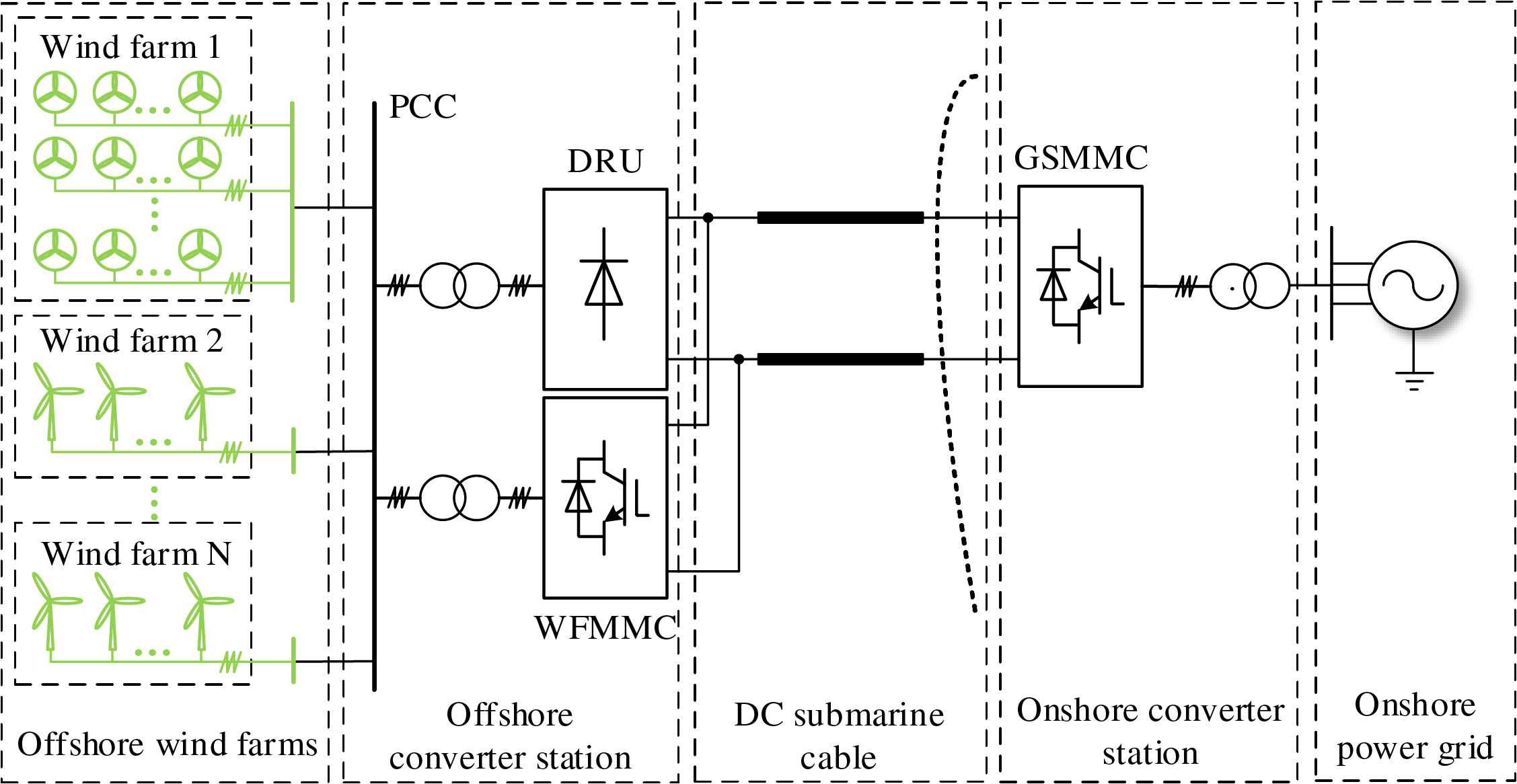
Figure 1: Structure of hybrid DRU-MMC based offshore wind power transmission system
2.1 Technical Feasibility of Hybrid DRU-MMC
The proposed hybrid DRU-MMC offshore wind power transmission system adopts a DC-side parallel configuration, which offers several important advantages in terms of both control flexibility and economic feasibility. In this configuration, the WFMMC is not responsible for transferring active power during steady-state operation; instead, all the active power generated by the offshore wind turbines is delivered to the onshore grid via the DRU. Besides, the low-capacity WFMMC can provide voltage support for the offshore AC system, eliminating the need for grid-forming wind turbines. This arrangement significantly reduces the power capacity, physical size, and conduction losses of the WFMMC, thereby lowering the overall investment and operation costs of the system. Compared with conventional compact MMC based offshore wind power transmission scheme, the total cost of hybrid DRU-MMC scheme reduces by 52.57% with the specific cost for semiconductor devices and operating loss reduced by more than 60% and 65%, respectively [16].
More critically, the DC-side parallel structure enables bidirectional power flow capability, which is not available in DRU-only or DRU-MMC series connected schemes without auxiliary equipment due to the unidirectional nature of DRU. With this topology, the WFMMC can operate as the power supply during black-start or abnormal conditions, providing the required power to energize the offshore wind farm and establish the offshore AC grid without relying on additional auxiliary sources such as battery energy storage systems. This significantly enhances the black-start capability and operational autonomy of the offshore wind farm.
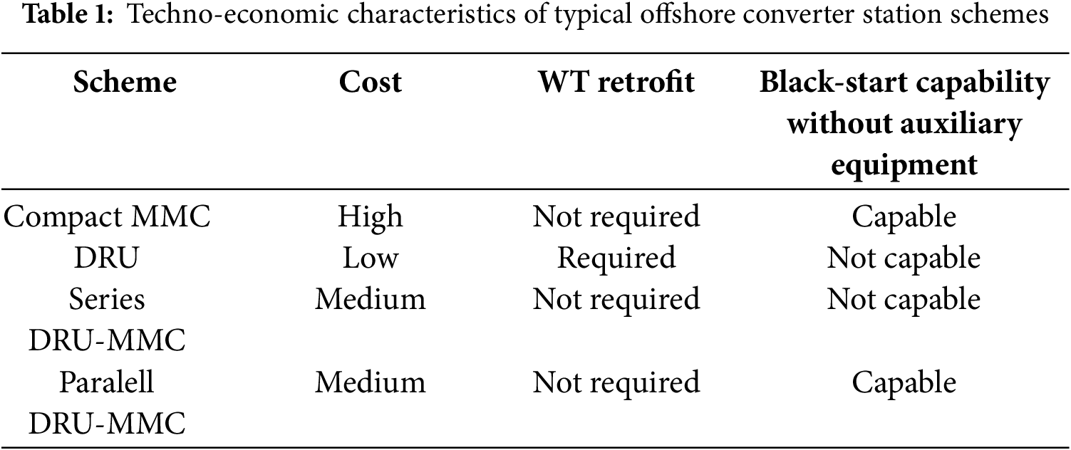
Furthermore, to ensure robust voltage support and reactive power control during transient and fault conditions, the system adopts a dual-parallel structure where the MMC and DRU are connected in parallel on both AC and DC sides. This architectural design allows the MMC to operate in voltage-source mode to support the offshore AC bus voltage during disturbances, while the DRU handles the bulk power transmission during normal operation. As a result, the proposed topology achieves an optimal balance between cost-effectiveness and control performance, making it technically feasible and well-suited for long-distance, large-capacity offshore wind power integration. The techno-economic characteristics of typical offshore converter station schemes for offshore wind power integration are summarized in Table 1.
2.2 Steady-State Characteristics
The detailed offshore converter station topology of the hybrid DRU-MMC offshore wind power transmission system is shown in Fig. 2, where ur and Ur represent the instantaneous and root mean square (RMS) values of the PCC (point of common coupling) AC voltage, respectively. ir denotes the AC current flowing into the DRU, while im denotes the AC current flowing out of the MMC. Pwf and Qwf are the active and reactive power outputs of the offshore wind farm, respectively. Pr and Qr denote the active power transmitted and reactive power absorbed by the DRU. Pm and Qm represent the active and reactive power outputs of the MMC. T and Xr are the turns ratio and leakage reactance of the DRU converter transformer, respectively. Kr denotes the number of series-connected 6-pulse DRUs on the DC side. Udcr is the DC voltage of a single 6-pulse DRU, which is approximately constant in steady-state and denoted as Uconst. KrUdcr and Idcr represent the total DC voltage and DC current of the rectifier station, respectively.
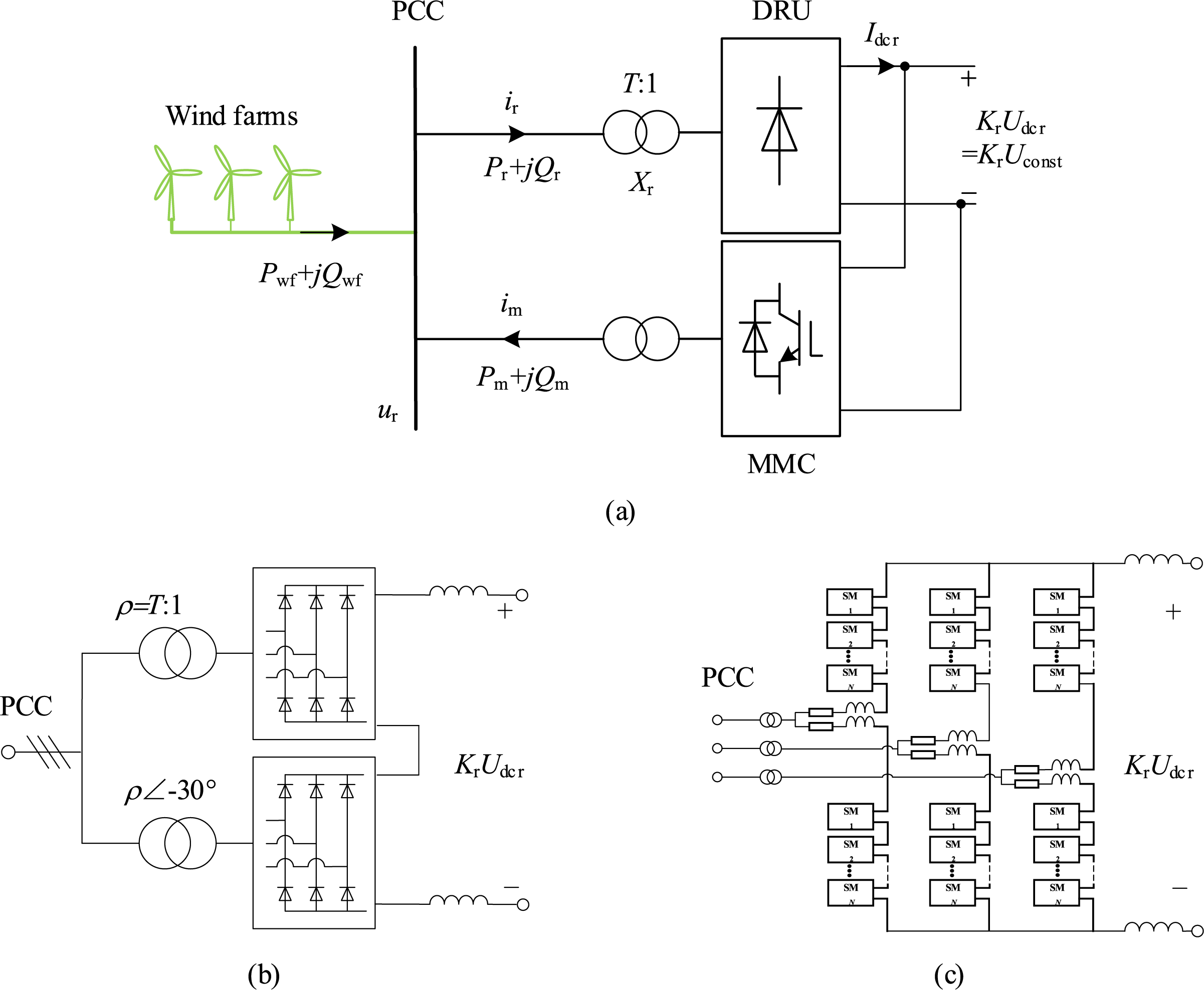
Figure 2: Offshore DRU-MMC Rectifier Station Model. (a) Overall structure; (b) DRU structure; (c) MMC structure
At the PCC, the windfarm MMC controls both the voltage amplitude and frequency, effectively serving as the slack node for the offshore AC system. From Fig. 2, the steady-state power flow can be derived as:
The active power Pr transferred by the DRU is linearly dependent on the AC voltage amplitude Ur under a fixed frequency f determined by the MMC control, which allows the MMC to indirectly regulate Pr by adjusting Ur. Hence, the MMC operates under a “zero active power” strategy, with all active power transmitted via the DRU. For reactive power, the DRU’s absorption Qr depends on its active power transfer Pr. Given that the grid-following wind turbines usually operate under fixed reactive power settings with a constant Pwf, the total reactive demand becomes a deterministic function of active output. The MMC compensates the net imbalance Qm, ensuring dynamic reactive power support for the offshore grid.
2.3 Control Strategy of the Windfarm MMC
The overall control structure of windfarm MMC (WFMMC) is illustrated in Fig. 3. The detailed control principle is not elaborated here and can be referred to in [16]. The control objectives of WFMMC mainly include: (1). AC Voltage Support (2). Active Power Control (3). Reactive Power Compensation (4). Active Harmonic Filtering.
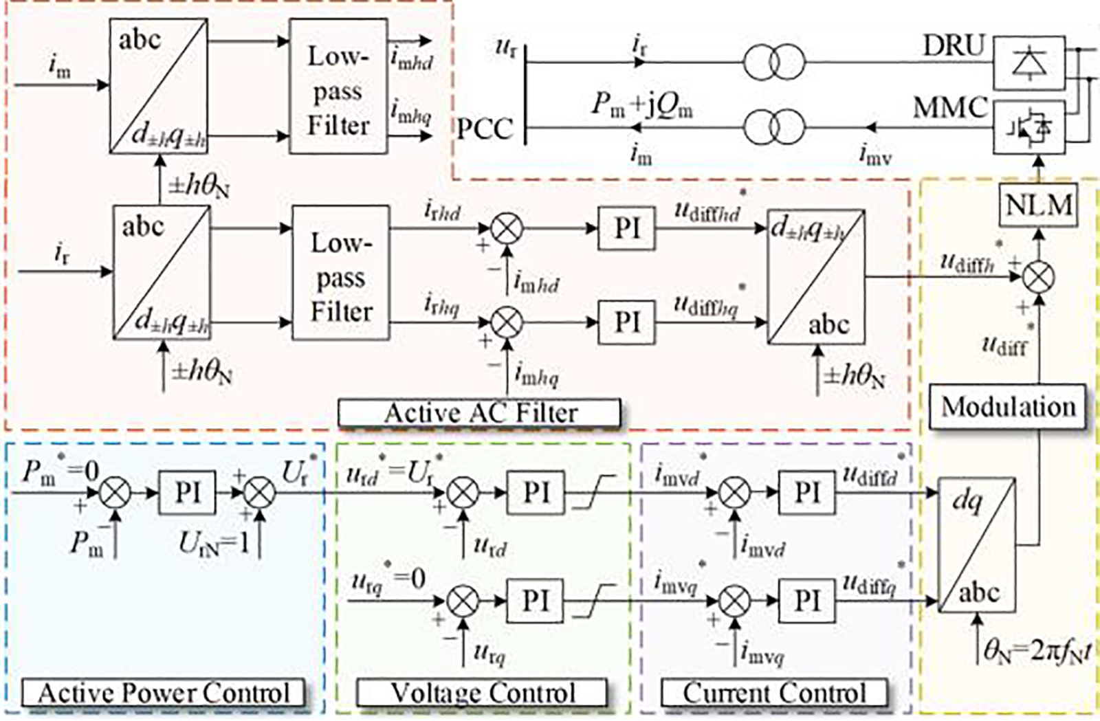
Figure 3: Control structure of windfarm MMC
2.4 Control Strategy of the Wind Turbine
The control structure of the grid-following wind turbine employing a permanent magnet synchronous generator (PMSG) is shown in Fig. 4.
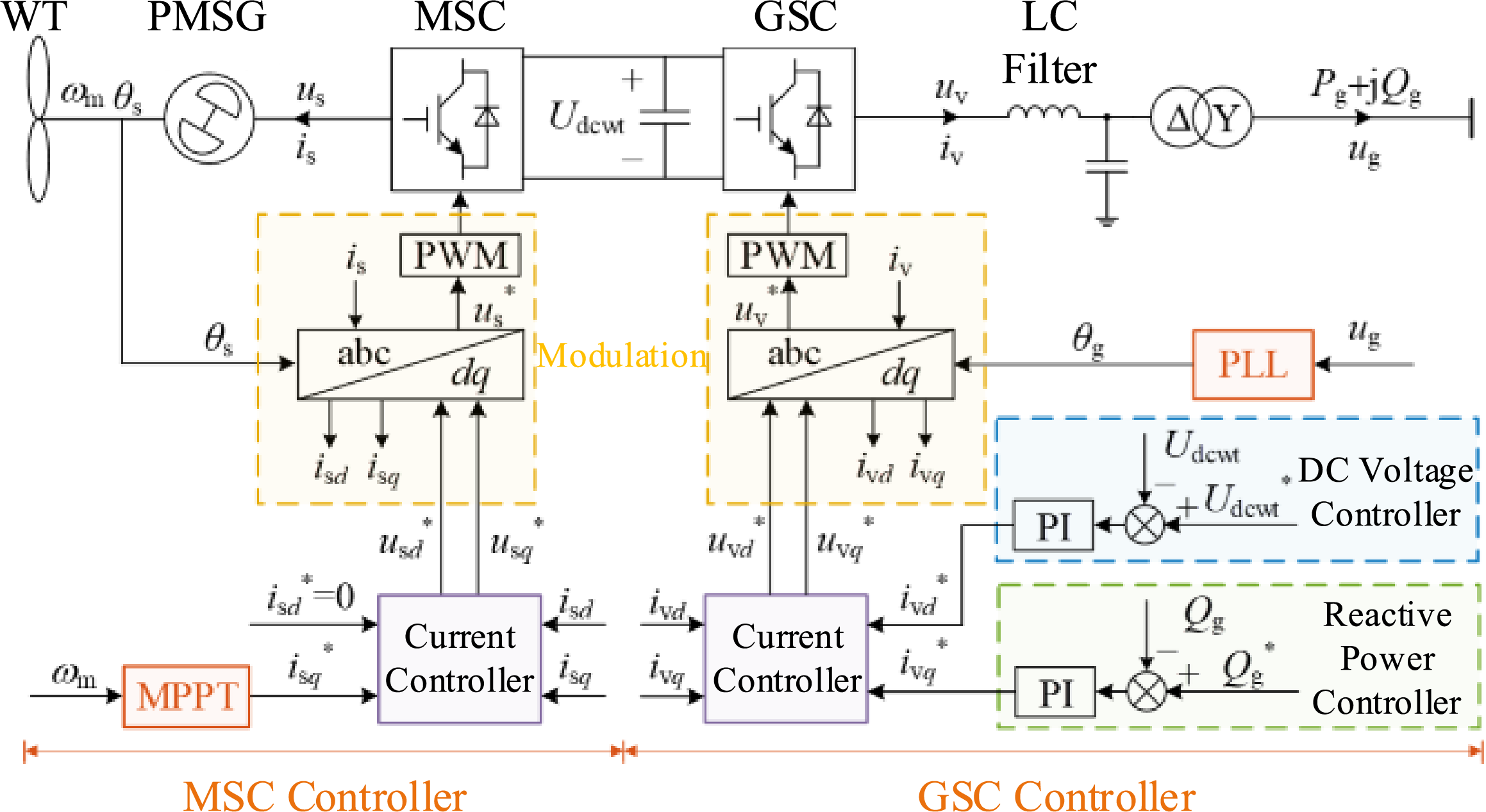
Figure 4: Control structure of the grid-following wind turbines
In Fig. 4, ωm is the rotor speed of the wind turbine, θs is the phase of the machine-side converter voltage, us and is are the AC voltage and current on the machine side, Udcwt is the DC link voltage of the back-to-back converter, uv and iv are the AC voltage and current on the grid side, ug is the AC voltage at the high-voltage side of the transformer, Pg and Qg are the active and reactive power outputs of the wind turbine, and θg is the phase angle of the grid-side converter voltage. Superscript “*” denotes reference values, and subscripts “d” and “q” represent the d and q components, respectively.
3 Offshore AC Fault Ride-through of the Hybrid System
3.1 Fault Characteristics of PCC Voltage and Power
Assuming the AC fault happens near the offshore PCC, the system power flow after offshore AC-fault is shown in Fig. 5. if denotes the fault current, Rf denotes the fault grounding resistance, idrf, iomf and iwff denote the fault current contributed by the DRU, windfarm MMC and wind farm, respectively.
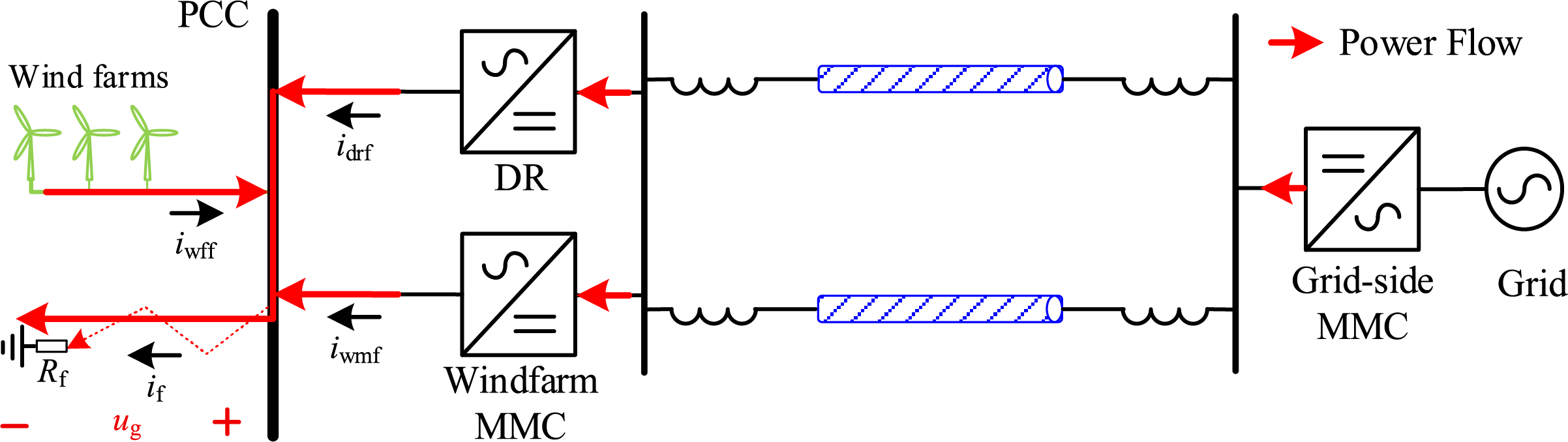
Figure 5: System power flow after offshore AC-fault
As shown in Fig. 5, the voltage magnitude at the PCC drops rapidly after fault. The offshore wind farm, onshore MMC, windfarm MMC and DRU will jointly contribute fault power to the short-circuit point. The PCC voltage ug and the active power Pf absorbed by the fault point can be calculated by:
As a current-source-type converter, the AC side of the DRU can be represented as a controlled current source, as shown in Fig. 6. idcdr and udcdr denote the DC side current and voltage of the DRU, udcdrh and udcdrl denote the DC side voltage of the high-valve and low-valve 6-pulse DRUs, respectively. Sdr reflects the switching-state of the DRU.
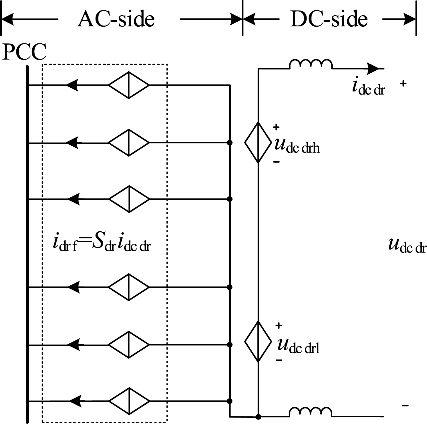
Figure 6: Equivalent dynamic model of the DRU
According to Fig. 6, the AC fault current contributed by the DRU is proportional to its DC current:
The DC voltage of 12-pulse DRU can be expressed as:
here, Xdr denotes the commutation reactance of the DRU, ρ denotes the transformer ratio.
After a three-phase fault occurs at the sending-end AC side, the DC voltage of the offshore converter station will drop rapidly with the decreased PCC voltage Ug according to Eq. (4), causing the onshore MMC to deliver power toward the offshore station, resulting in a power flow reversal. The DC current of DRU can be expressed as:
here, udcgm denotes the DC-side voltage of the grid-side MMC, idcwm denotes the DC-side current of the windfarm MMC, Rcable denotes the line resistance of the DC submarine cable.
From Eq. (5), it can be known that the DC current of DRU will quickly decrease due to the drop in DC voltage. However, as the DRU’s DC current idcdr decreases to zero, it will not continue to drop into negative values due to the unidirectional conduction characteristic of the diodes in the DRU, instead, idcdr will be clamped at zero. Combined with Eq. (3), the AC fault current contributed by the DRU is also approximately zero:
Combined with Eq. (2), the PCC voltage and the active power absorbed by the fault point becomes:
The above equations indicates that, for the hybrid DRU-MMC based wind power integration system, after a three-phase AC fault occurs at the sending end, the PCC voltage and the power absorbed at the fault point are mainly determined by the grounding resistance and the magnitude of the AC fault current provided by the wind farm and the windfarm MMC during the fault. The DRU has minimal impact on the AC fault characteristics. In addition, as the grounding resistance decreases, both the active power consumed at the fault point and the PCC voltage will drop. Under metallic fault conditions, regardless of how much AC current is supplied by the wind turbines and the windfarm MMC, it is still difficult to establish the PCC voltage, which remains nearly zero.
3.2 Current Saturation Risk of Windfarm MMC during Post-Fault Recovery
Due to the limited overcurrent tolerance of power electronic devices, the current command values imvd* and imvq* generated by the windfarm MMC’s voltage controller (Fig. 3) are subject to hard current limiting. From the perspective of the offshore AC system, the external characteristics of the MMC go through three stages during the fault event:
1. Normal Operation: The current command remains within limits under the combined action of the active power controller and voltage controller. The MMC behaves as a voltage source with controllable magnitude and constant frequency at the PCC.
2. During the AC Fault: The PCC voltage drops, driving the MMC current command to its limit. The MMC enters a current saturation state, effectively behaving as a constant-magnitude, constant-phase current source.
3. Post-Fault Recovery: The MMC should quickly restore its voltage-source behavior and support the AC system voltage.
However, as the fault is cleared and the AC voltage at the point of common coupling gradually recovers, the wind turbine generator (WTG) begins to restore its active power output in accordance with its constant active power control loop. Meanwhile, the DRU operates as a passive converter, transfers the received AC active power to the DC side based on the magnitude of the AC voltage. Since the DRU’s power transfer capability is positively correlated with the PCC voltage amplitude, its ability to accept active power is initially limited during the voltage ramp-up process.
This leads to a temporary mismatch between the ramp-up rates of the WTG output and the DRU acceptance capacity. As a result, a portion of the generated active power cannot be totally absorbed by the DRU and becomes surplus power in the offshore AC system. According to the power balance relationship described in Eq. (1), this surplus active power is inevitably injected into the WFMMC, which is originally intended to operate without active power transmission under steady-state conditions. Consequently, the WFMMC’s current reference rises sharply and may reach the predefined saturation limit (1.2 p.u.) as shown in Fig. 7.
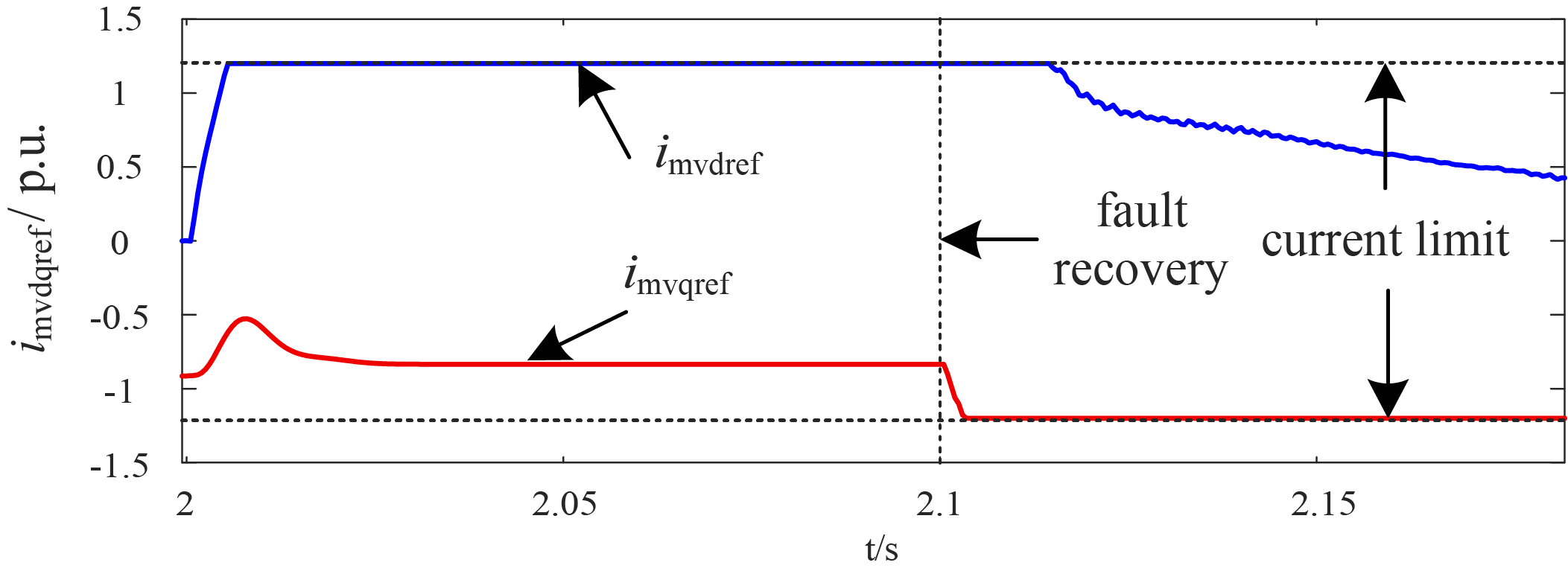
Figure 7: WFMMC current reference after fault
Once the WFMMC current controller hits the saturation threshold, the converter loses its ability to regulate the AC voltage effectively, behaving as a current source rather than a voltage source. This undermines the voltage-source functionality that is essential for the re-establishment of the offshore AC grid. If this occurs, the voltage recovery process will be compromised, possibly leading to secondary voltage collapse or prolonged instability of the offshore grid.
The active power flow direction of wind turbines is shown in Fig. 8, through which the active power transfer relationship of wind turbines can be derived:
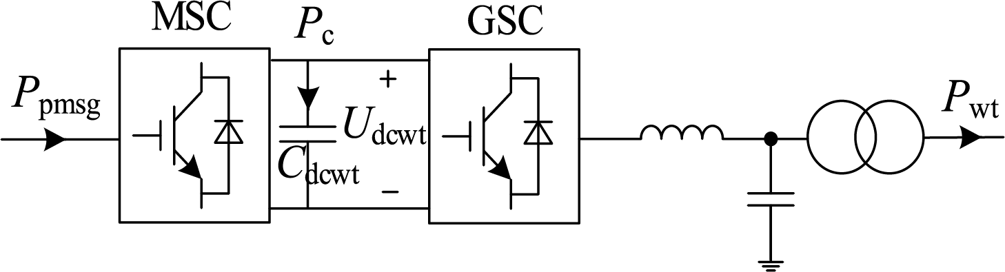
Figure 8: Active power flow direction of wind turbines
According to Eq. (7), the PCC voltage will drop significantly after the fault. As a result, the grid-side converter of the wind turbine will be unable to export all the power generated by the turbine, and the surplus power will be absorbed by the DC-side capacitance Cdcwt of the back-to-back wind turbine converter, causing DC-link overvoltage.
To support the WTG in riding through offshore AC faults, a DC chopper circuit is installed on the DC side of the converter. This circuit maintains the DC voltage Udcwt during periods when the grid-side converter is power-constrained.
3.4 Piecewise Fault Ride-through Strategy of Hybrid DRU-MMC Based Offshore Wind Farms
According to Eq. (7), in the hybrid DRU-MMC system, the DRU loses its ability to influence the fault characteristics after a sending-end AC fault. To provide voltage support at the offshore point of common coupling (PCC) during the fault, both the grid-side converter of the wind turbine and the windfarm MMC must supply sufficient AC current to the PCC. Therefore, this paper proposes a fault ride-through strategy for the hybrid DRU-MMC system that coordinates the reactive current support capabilities of the windfarm MMC and the wind turbine grid-side converter.
3.4.1 Protection Criterion for Offshore AC Symmetrical Fault
When the RMS voltage of the offshore PCC Ug is detected to drop below 0.8 p.u., the system is determined to have experienced an AC fault, and the signal Ctrlac1 switches to 0:
After the system detects an AC fault, and the rate of rise of the AC bus voltage exceeds the threshold value Kt, the system determines that the fault has been cleared and starts the fault recovery (signal Ctrlre switches to 1):
The switching signal of the chopper circuit is:
As illustrated in Fig. 9, During normal operation, the chopper remains blocked. When the DC voltage exceeds an upper threshold UdcwtH, the chopper is triggered, and the surplus energy is dissipated through the braking resistor. Once the DC voltage drops below the lower threshold UdcwtL during post-fault recovery, the chopper is blocked again, and the WTG resumes normal operation.
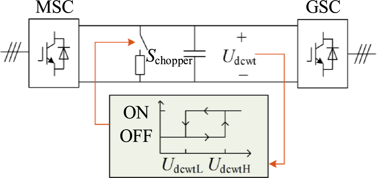
Figure 9: Protection strategy of the wind turbine generator DC chopper circuit
3.4.2 WT GSC Control during Offshore AC Fault and Post-Fault Recovery
To support the PCC voltage during the offshore AC fault and prevent MMC current saturation during post-fault recovery at the same time, a piecewise active current suppression control is implemented for the WTG grid-side converter:
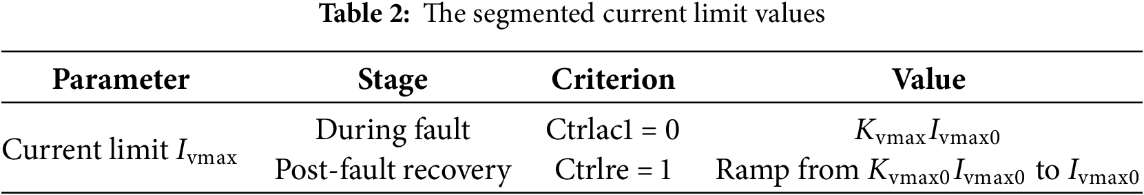
1. When signal Ctrlac1 switches to 0 (indicates that an offshore AC fault has occurred in the system), the current limit Ivmax is chosen as Kvmax of its nominal steady-state value Ivmax0 in order to effectively support the AC bus voltage during a grid fault by maximumly output the AC current within the tolerance capability of the power electronic devices according to Eq. (7). Kvmax should be selected according to the following principles:
Accordingly, Kvmax is chosen as 1.2 in this paper.
2. After the fault is cleared and Ctrlre switches to 1, a ramp limiter gradually increases Ivmax from Kvmax0Ivmax0 to Ivmax0, allowing a smooth recovery of the current reference. To prevent MMC current saturation during post-fault recovery, Kvmax0 should satisfy:
This method not only ensures that the WTG can effectively support the PCC voltage during the fault but also effectively limits the rapid restoration of active power, thereby avoiding MMC saturation and enabling it to maintain voltage-source characteristics for successful offshore AC voltage recovery. The segmented current limiting strategy is summarized in Table 2.
After obtaining the current limit, the steady-state outer control loops of the wind turbine grid-side converter for DC voltage and reactive power are frozen, and the control mode is switched to constant AC current control to provide the maximum possible support for the AC bus voltage. The DQ-axis current references for the constant AC current control are given by the following equation:
In Eq. (14), current limit Ivmax can be derived from the active current suppression control, iv is the AC current on the grid side, IvN is the nominal AC current, Kvq is the reactive current share coefficient. Superscript “*” denotes reference values, and subscripts “d” and “q” represent the d and q components, respectively.
The overall block diagram of the wind turbine grid-side converter control during AC fault is shown in Fig. 10.
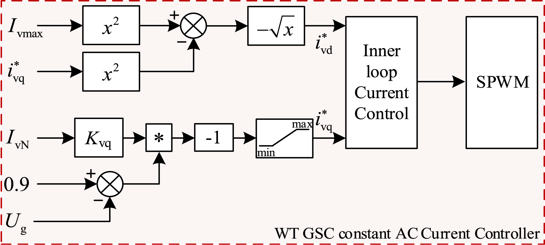
Figure 10: Wind turbine grid-side converter constant AC current control during AC fault
3.4.3 Selection of Reactive Current Share Coefficient Kvq
According to Eq. (14), the reactive current share coefficient Kvq need to be selected to meet the dynamic performance requirements of the system. Fig. 11 illustrates the dynamic response of the offshore AC bus voltage Ug after offshore AC grounding fault (occurs at t = 2 s, clear at t = 2.2 s, Rf = 0.9 Ω) under different values of Kvq.
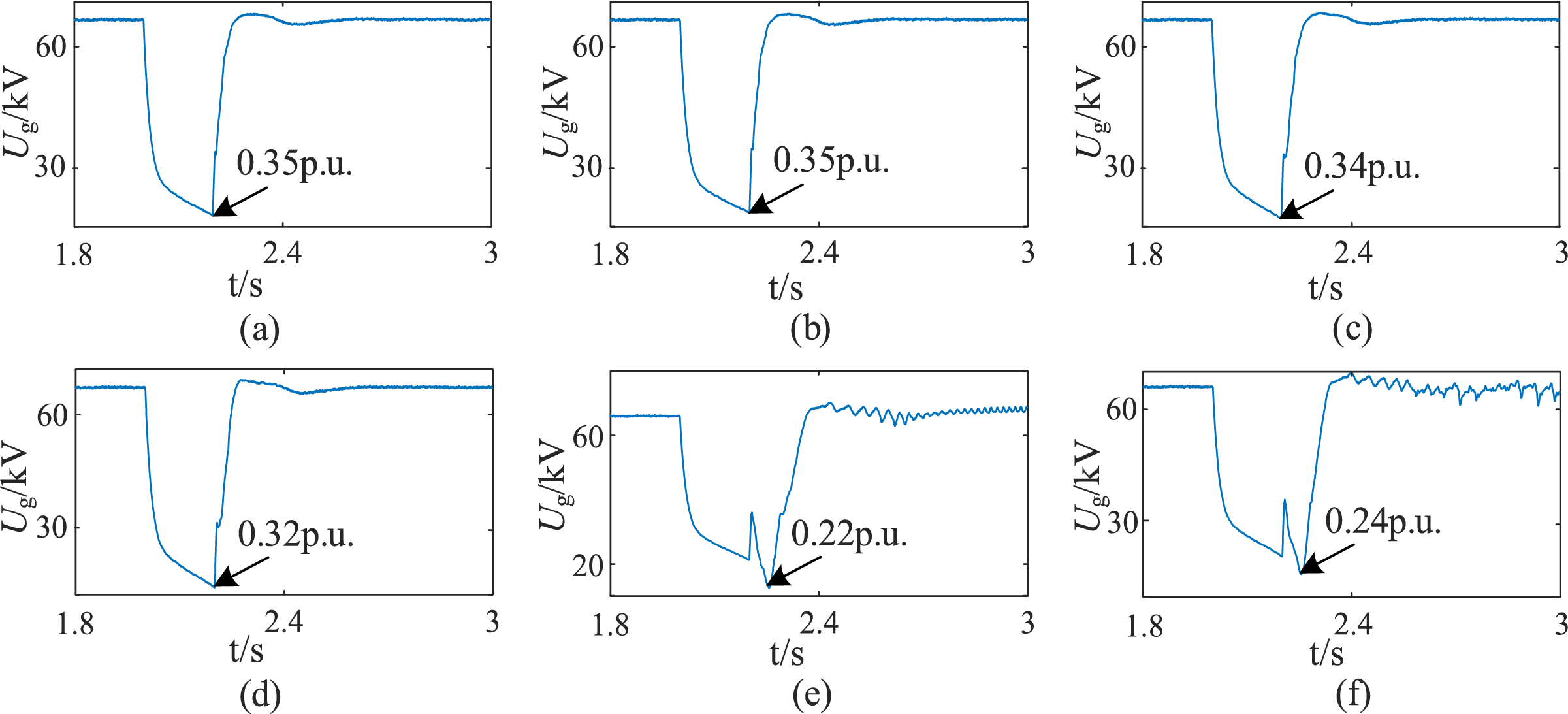
Figure 11: Dynamic response of the offshore AC bus voltage. (a) Kvq = 0.9; (b) Kvq = 1; (c) Kvq = 1.17; (d) Kvq = 1.2; (e) Kvq = 1.25; (f) Kvq = 1.3
It can be seen that when Kvq increases, the grid-side converter of the wind turbine provides less support to the offshore AC bus voltage, causing the severe drop of PCC voltage during the fault. Moreover, when Kvq is set too high (e.g., Kvq >1.2), the system exhibits instability during the fault period. The recommended range for the positive-sequence dynamic reactive current injection coefficient of wind farms, as specified by the latest Chinese national standard, is 1.17 to 2.33. Therefore, in this paper, Kvq is set to 1.17, under which the offshore AC bus voltage drops to a minimum of 0.34 p.u. during the fault.
3.4.4 Selection of Ramp Limiter Parameters during Fault Recovery
The parameters of the current ramp limiter include the initial ratio Kvmax0 and the maximum ramp-up rate Kvimax. The design objective of the current limit ramp-up rate limiter during the fault recovery stage is to ensure that the MMC current control reference does not reach the saturation limit—thus retaining the capability to re-establish the PCC voltage—while achieving the fastest possible fault recovery.
Fig. 12 illustrates the dynamic response of the MMC current limit after offshore AC grounding fault (occurs at t = 2 s, clear at t = 2.2 s, Rf = 0.9 Ω) under different values of Kvmax0. As shown in the figure, a smaller value of Kvmax0 leads to a shorter time for the MMC current reference to exit saturation during the fault recovery period. The specific desaturation times are listed in Table 3. Considering the detection delay of the ramp-up rate, a desaturation time within 10 ms is acceptable. Therefore, the value of Kvmax0 is set to 0.1 in this paper.
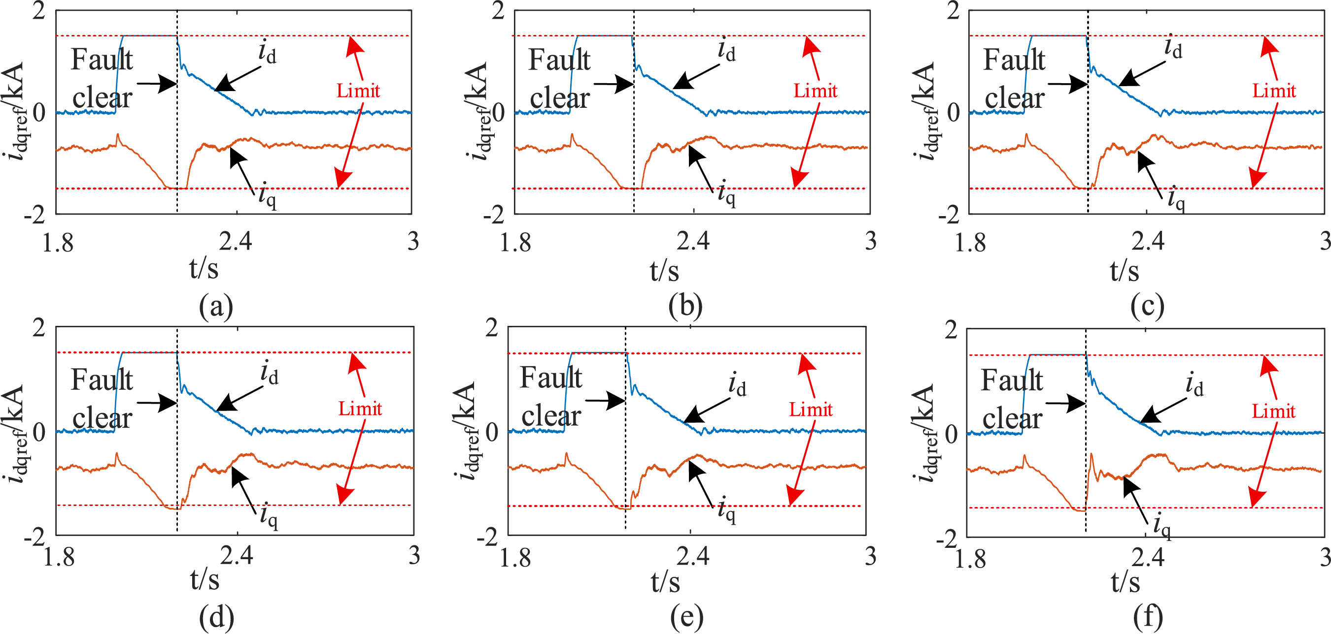
Figure 12: Dynamic response of the MMC current limit under different values of Kvmax0. (a) Kvmax0 = 0.9; (b) Kvmax0 = 0.8; (c) Kvmax0 = 0.7; (d) Kvmax0 = 0.6; (e) Kvmax0 = 0.5; (f) Kvmax0 = 0.1
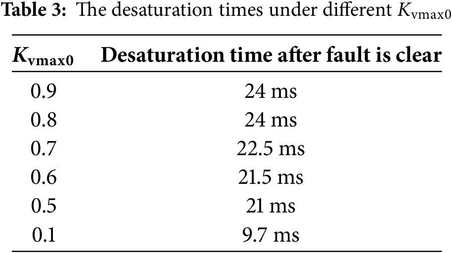
Fig. 13 illustrates the dynamic response of the MMC current limit after offshore AC grounding fault (occurs at t = 2 s, clear at t = 2.2 s, Rf = 0.9 Ω) under different values of Kvimax.
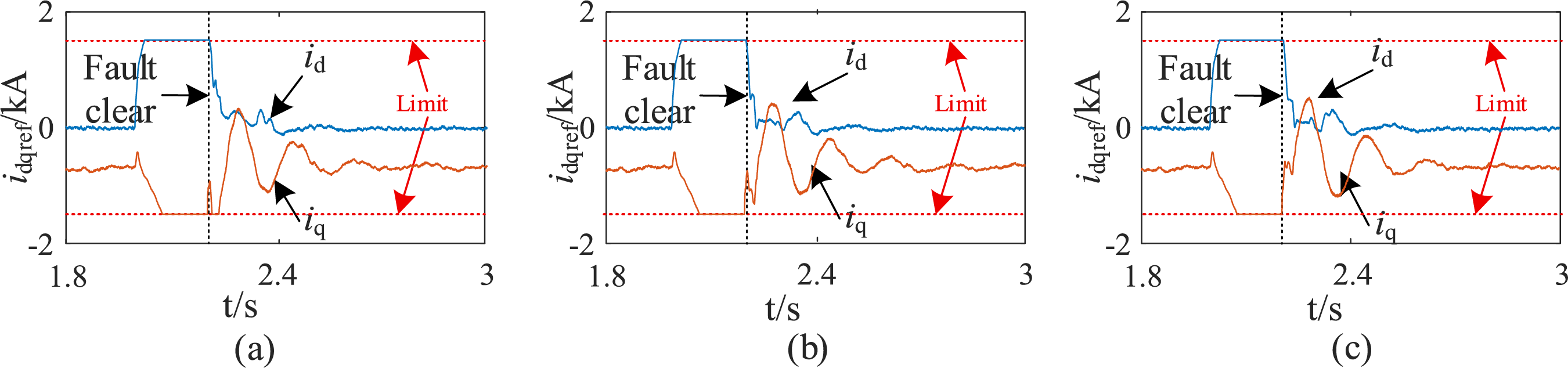
Figure 13: Dynamic response of the MMC current limit under different values of Kvimax. (a) Kvimax = 30; (b) Kvimax = 20; (c) Kvimax = 19
Fig. 14 illustrates the dynamic response of the PCC voltage after fault under different values of Kvimax.
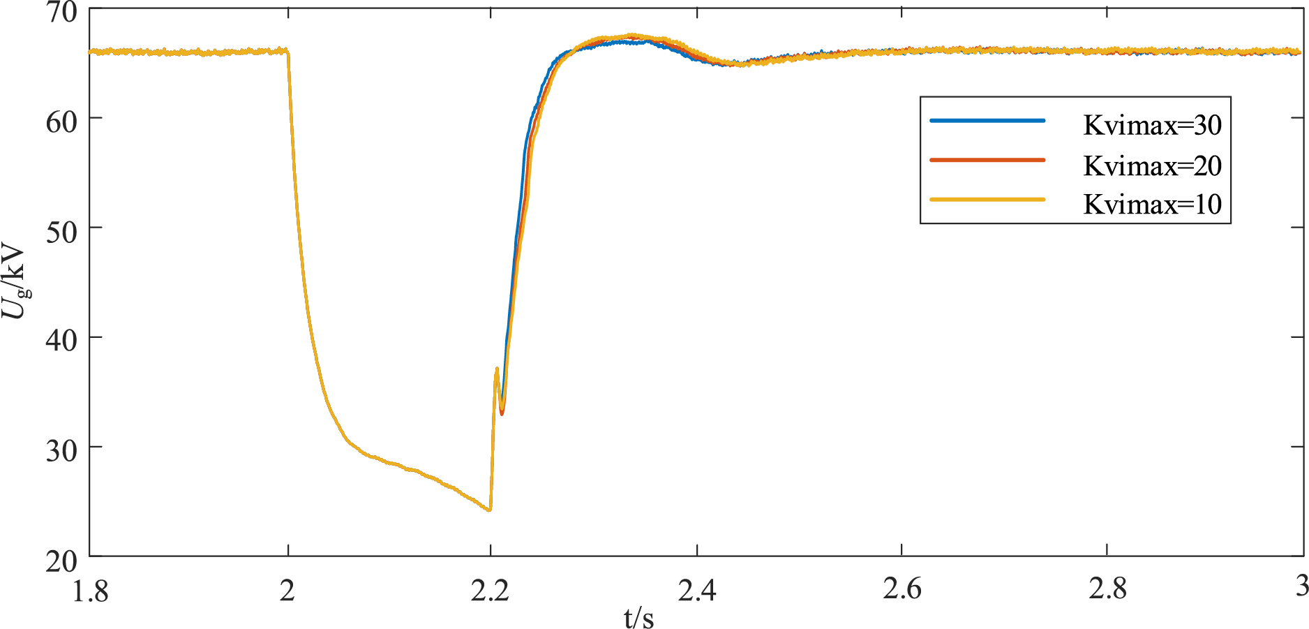
Figure 14: Dynamic response of the PCC voltage limit under different values of Kvimax
It can be observed that as Kvimax increases, the overshoot of the PCC voltage during the fault recovery process decreases. However, when Kvimax becomes too large, the MMC current reference may reach the saturation limit. Therefore, Kvimax is set to 20 in this paper.
3.4.5 Windfarm MMC Control during AC Fault and Post-Fault Recovery
After offshore AC fault happens, the windfarm MMC’s outer voltage control loop and active AC filter control are frozen and switched to constant AC current control, with a control structure similar to that of the WTG grid-side converter. The key difference lies in the current limiting strategy: to avoid saturation of the current reference during fault recovery while providing maximum voltage support at the offshore PCC during the fault, the current limit for the MMC is set to a fixed value of 1.5 throughout both the fault and post-fault recovery periods, considering the MMC’s higher short-term overcurrent tolerance. The corresponding control block diagram is shown in Fig. 15.
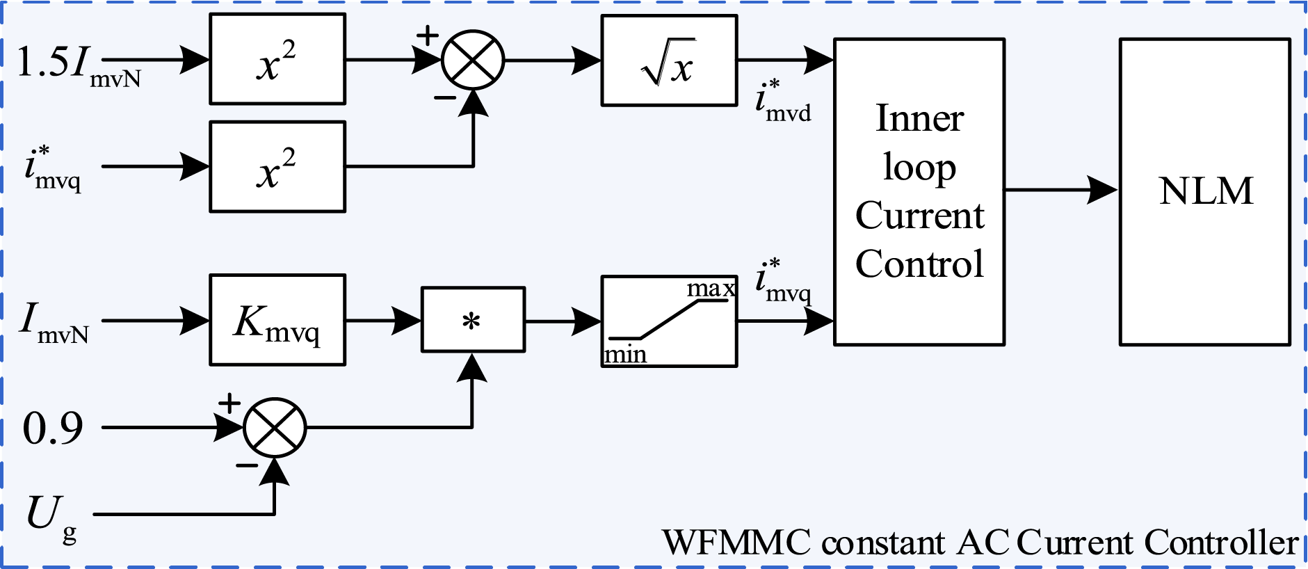
Figure 15: WFMMC control during AC fault and post-fault recovery
During the fault period, the MMC’s constant AC current control also requires proper selection of the reactive current sharing coefficient Kmvq. Similar to the WTG converter, as the MMC’s reactive current coefficient increases, its ability to support the AC bus voltage during the fault decreases, which may even lead to system instability. Therefore, Kmvq is set to 1.17 in this paper.
This section will verify the effectiveness of the proposed offshore wind power DC transmission scheme based on the hybrid DRU-MMC and the system’s offshore AC fault ride-through capability through an electromagnetic transient simulation model built in PSCAD/EMTDC, as shown in Fig. 16.
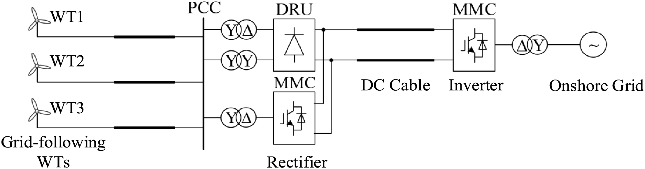
Figure 16: Electromagnetic transient simulation model
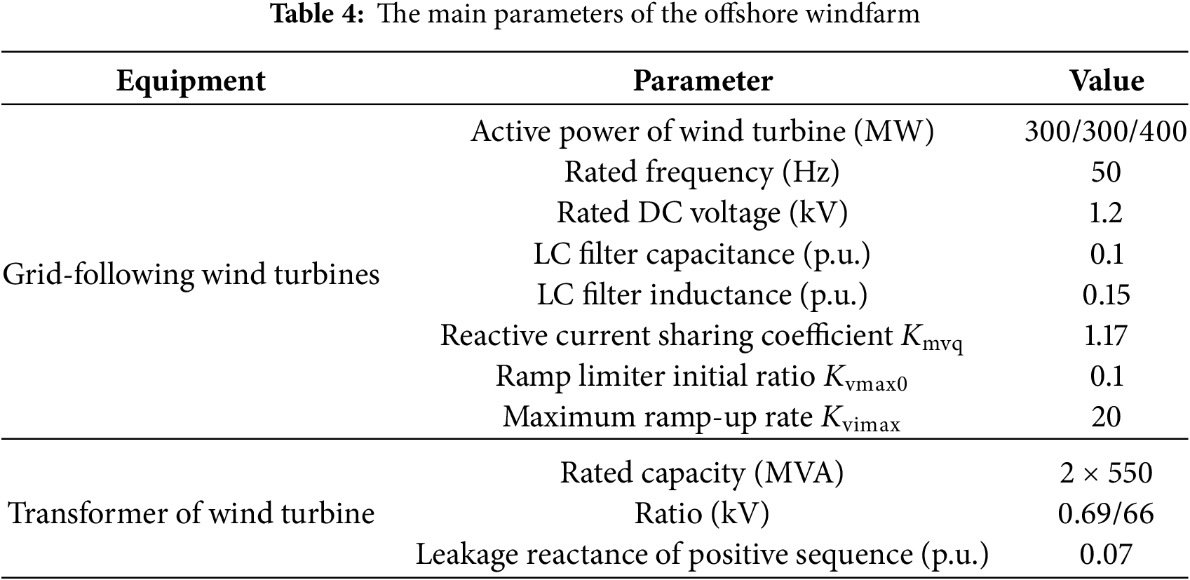
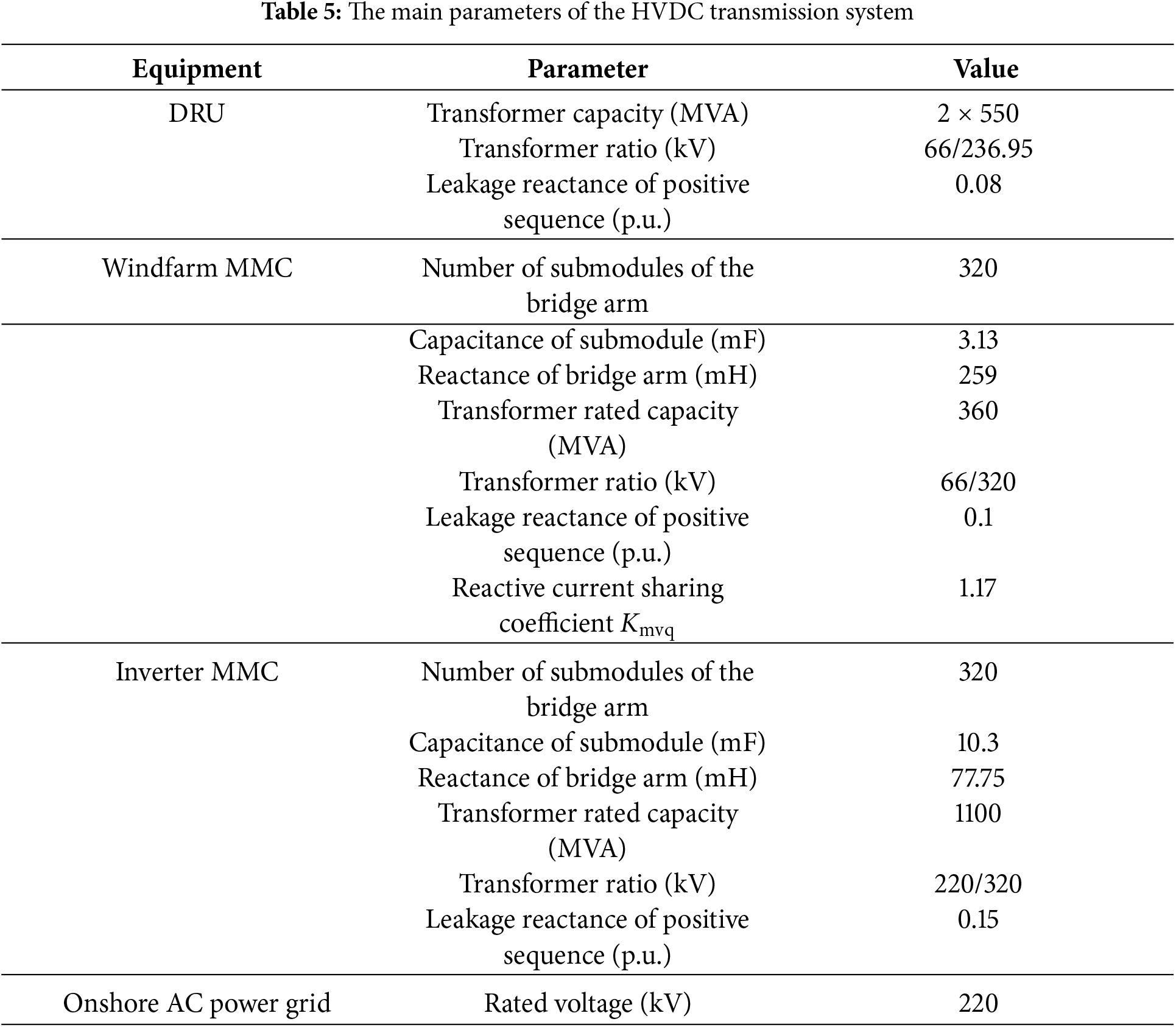
Simulations are carried out under system steady-state and offshore AC faults. The test system includes a 1000 MW offshore wind farm composed of three equivalent grid-following wind turbine generators (WTGs). The main parameters of the transmission scheme for offshore wind farms are shown in Tables 4 and 5.
To validate the feasibility of the proposed DRU-MMC hybrid offshore wind power transmission system, the steady-state operating performance is simulated. The results are shown in Figs. 17 and 18.
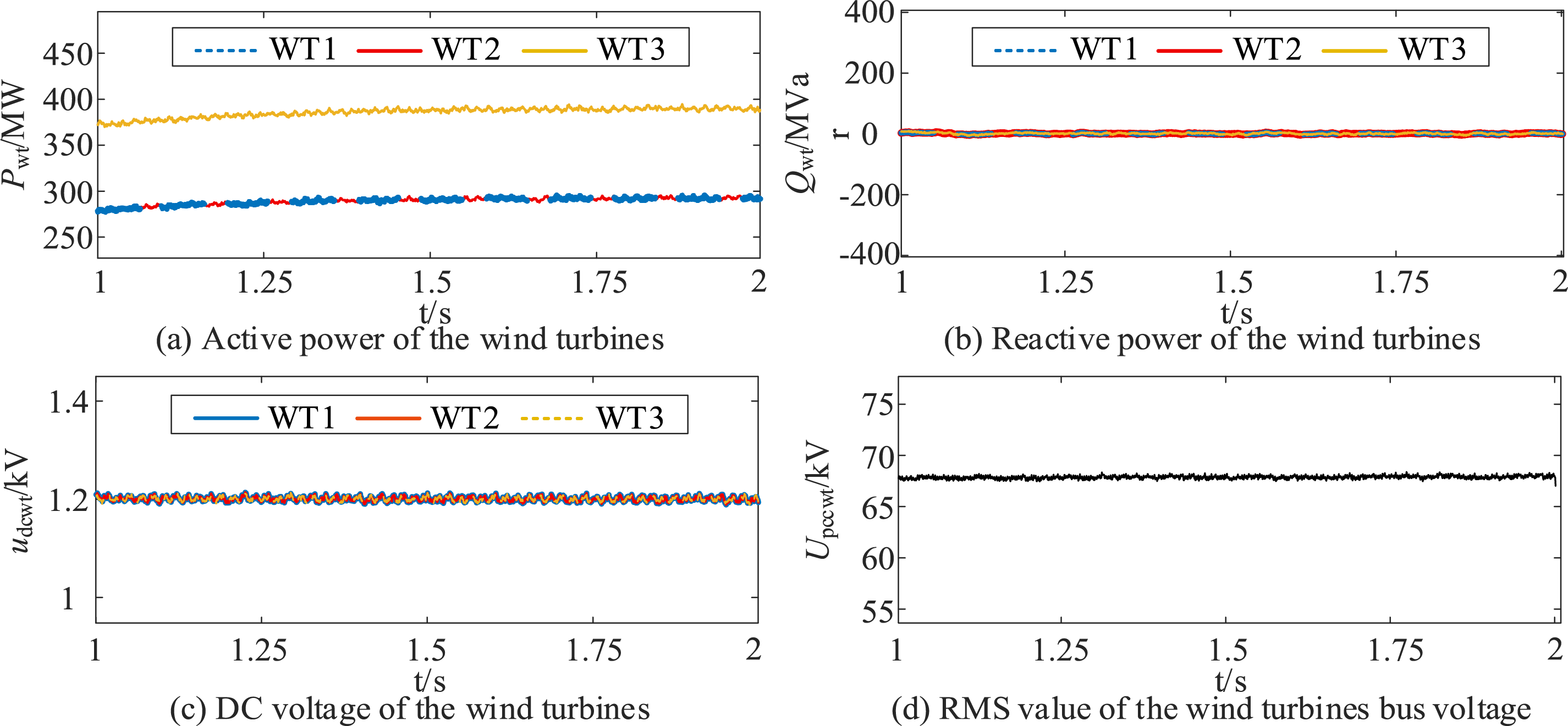
Figure 17: Steady-state characteristics of the wind-turbines
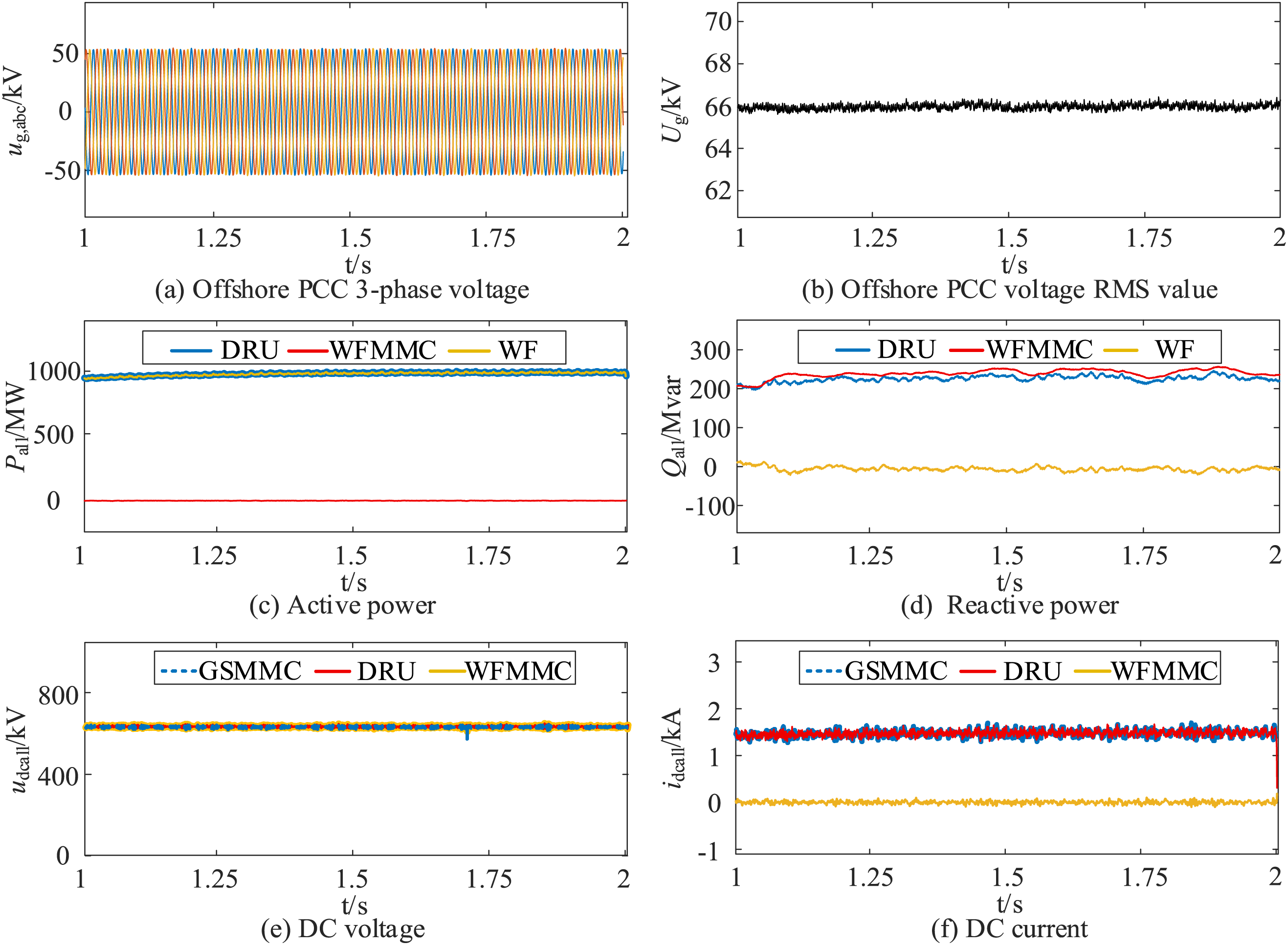
Figure 18: Steady-state characteristics of the GSMMC, WFMMC, DRU and windfarm (WF)
The simulation results demonstrate that the DRU-MMC hybrid offshore wind power transmission system can operate steadily under rated conditions. The WFMMC does not transfer active power, as the entire active power output from the wind turbines is transmitted by the DRU. Meanwhile, the reactive power generated by the DRU is fully compensated by the WFMMC, validating the effectiveness of the proposed scheme.
To validate the offshore AC fault characteristic analysis and proposed fault ride-through strategy, the operating performance during fault and post-fault recovery is simulated. A metallic offshore AC symmetric short-circuit occurs at t = 2.0 s and the fault is clear at t = 2.2 s. The results are shown in Figs. 19 and 20.
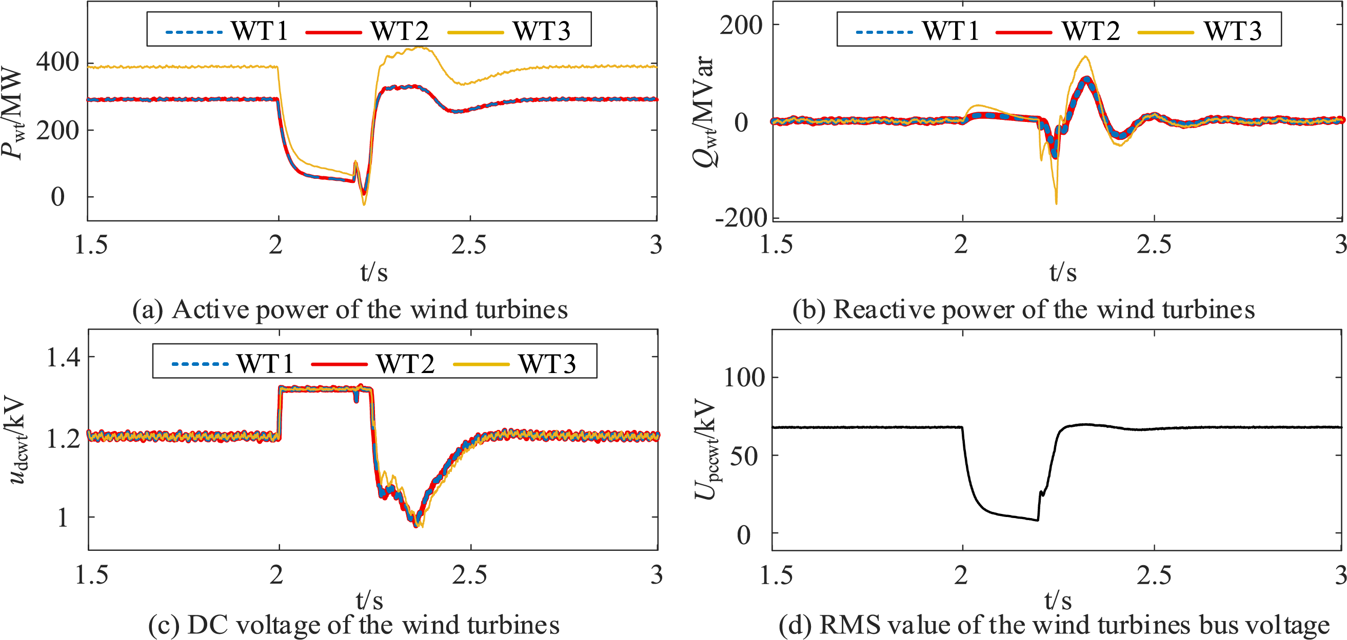
Figure 19: Offshore AC fault characteristics of the wind-turbines
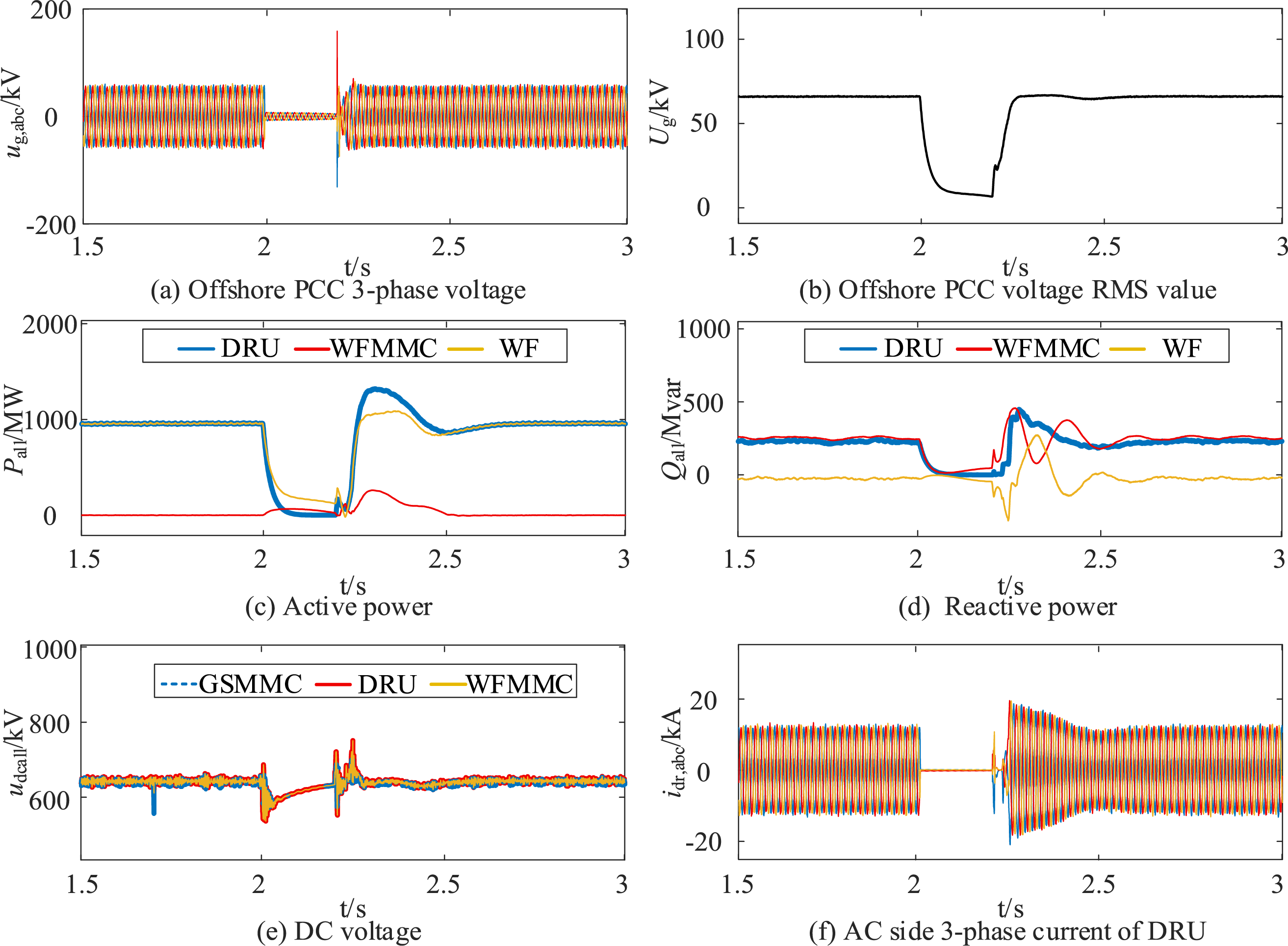
Figure 20: Offshore AC fault characteristics of the GSMMC, WFMMC, DRU and windfarm (WF)
The simulation results show that after a metallic offshore AC symmetric short-circuit, the AC current of the DRU rapidly drops to zero, contributing no fault current during the fault period, which confirms the fault characteristic analysis presented in this paper. Moreover, under the proposed fault ride-through strategy, the offshore PCC voltage is effectively supported during the fault, and the current reference of the MMC controller does not reach the saturation limit during post-fault recovery. This enables a fast and stable fault recovery process, thereby validating the effectiveness of the proposed fault ride-through strategy.
This paper investigates the fault characteristics of a DRU-MMC hybrid offshore wind power transmission system under offshore three-phase symmetrical AC faults, and proposes a coordinated fault ride-through (FRT) strategy based on segmented current limiting control for the wind turbine generator (WTG) side converter and constant AC current control for the wind farm MMC (WFMMC). The main conclusions are summarized as follows:
1. After an offshore AC fault occurs, the AC current of the DRU drops rapidly to zero due to the unidirectional conduction characteristics of its diodes. As a result, the DRU does not contribute any fault current, and the total fault current is solely provided by the WFMMC and the WTG-side converters.
2. During the fault period, only the WFMMC and WTG-side converters are capable of supporting the offshore AC bus voltage. To maximize voltage support, both converters should contribute fault currents with maximum amplitude and identical phase.
3. In the fault recovery stage, a mismatch between the ramp-up speed of WTG active power output and the DRU’s power acceptance capacity may occur, leading to surplus active power being injected into the WFMMC. This may cause the MMC’s current command to reach its saturation limit, degrading it into a current source and disabling voltage regulation at the PCC. This issue can be mitigated by implementing ramp limiter on the WTG output current during post-fault recovery.
4. By properly designing the reactive current share coefficient and ramp limiter parameters, the proposed FRT strategy enables the DRU-MMC hybrid offshore wind power transmission system to safely ride through offshore AC faults and to recover from faults rapidly and smoothly.
The analysis in this paper reveals that during offshore AC faults, the WTG-side converter should ideally generate fault current with the same phase as the WFMMC in order to maximize the voltage support capability at the PCC. However, in practice, the fault current of WTGs is often difficult to measure accurately. Future research could explore the application of sliding mode control to enable the WFMMC to dynamically adjust the reference phase of its constant AC current control during fault conditions, aligning it with the unmeasurable WTG fault current in real time. Additionally, in the proposed FRT strategy, parameters such as the reactive current share coefficient were selected based on simulation studies. Future work may consider incorporating optimization algorithms to systematically design and tune these parameters, thereby improving the adaptability and performance of the FRT strategy under a wider range of fault scenarios. Besides, while this paper mainly focuses on the fault ride-through strategy of the WT GSC and the WFMMC, the control strategy at the WT machine-side converter during fault remains to be studied.
Acknowledgement: Not applicable.
Funding Statement: This project is funded by the Science and Technology Projects of State Grid Zhejiang Electric Power Co., Ltd. (5211DS24000G).
Author Contributions: The authors confirm contribution to the paper as follows: study conception and design: Zheren Zhang, Haokai Xie, Sihao Fu, Wenyao Ye, Zheng Xu; data collection: Yi Lu, Sihao Fu, Haokai Xie; analysis and interpretation of results: Sihao Fu, Zheren Zhang, Haokai Xie, Xiaojun Ni; draft manuscript preparation: Xiaojun Ni, Yilei Gu, Sihao Fu, Zheren Zhang. All authors reviewed the results and approved the final version of the manuscript.
Availability of Data and Materials: The datasets used and/or analyzed during the current study are available from the corresponding author upon reasonable request.
Ethics Approval: Not applicable.
Conflicts of Interest: The authors declare no conflicts of interest to report regarding the present study.
References
1. Liu X, Han W, Liu Z, Han H, Su M, Li C, et al. Active fault current limitation for VSC-MTDC integrated offshore wind farms participating in frequency regulation. IEEE Trans Sustain Energy. 2024;15(2):773–88. doi:10.1109/tste.2023.3305310. [Google Scholar] [CrossRef]
2. Huang P, Zhou N, Luo Y, Duan X, Wang Q. Impedance coupling suppression control method for offshore wind farms integrated with MMC-HVDC system. IEEE Trans Ind Electron. 2025;72(6):6015–26. doi:10.1109/TIE.2024.3493159. [Google Scholar] [CrossRef]
3. Cao P, Fan H, Cai Z. Adaptive fractional-order PID control for VSC-HVDC systems via cooperative beetle antennae search with offshore wind integration. Energ Eng. 2021;118(2):265–84. doi:10.32604/ee.2021.014513. [Google Scholar] [CrossRef]
4. Ye H, Chen W, Li T, Liu X, Liu G. A novel cost-effective HVDC system with self black-start and fault ride-through capability. IEEE Trans Sustain Energy. 2025;16(3):1629–43. doi:10.1109/tste.2024.3522167. [Google Scholar] [CrossRef]
5. Xing L, Wei Q, Li Y. A PWM current-source converter-based wind energy conversion system. IEEE Trans Power Electron. 2024;39(2):2787–97. doi:10.1109/TPEL.2023.3333315. [Google Scholar] [CrossRef]
6. Lei Z, Wang X, Zhou S, Wang Z, Wang T, Yang Y. A review of research status and scientific problems of floating offshore wind turbines. Energ Eng. 2022;119(1):123–43. doi:10.32604/ee.2022.016034. [Google Scholar] [CrossRef]
7. Chen L, Wang J, Li Z, Guo C, Zhang B, Li Z. Steady-state analysis of the DR-MMC based hybrid topology for offshore wind power transmission. IEEE Trans Power Electron. 2025;40(2):3177–88. doi:10.1109/tpel.2024.3483928. [Google Scholar] [CrossRef]
8. Fu S, Luo Y, Lyu Y, Tang Y, Zhu X, Huang P, et al. Analytical calculation of DC fault current of 12-pulse actively commutated current source converter. IET Conf Proc. 2025;2025(1):142–6. doi:10.1049/icp.2025.0460. [Google Scholar] [CrossRef]
9. Feng D, Xiong X, Yao C, Zhou Z, Zhao C. Cooperative control of FFM-CSC using positive and negative trigger angle for offshore wind power transmission. IEEE Trans Power Del. 2025;40(3):1574–86. doi:10.1109/tpwrd.2025.3555254. [Google Scholar] [CrossRef]
10. Bai R, Zhao B, Zhou T, Tang X, Li J, Cui B, et al. PWM-current source converter based on IGCT-in-series for DC buck and constant-current application: topology, design, and experiment. IEEE Trans Ind Electron. 2023;70(5):4865–74. doi:10.1109/tie.2022.3186385. [Google Scholar] [CrossRef]
11. Fu S, Xu L, Wang Q, Luo Y, Zhou N, Huang P. Dynamic models for DC fault analysis of actively commutated CSC-HVDC under different grid strengths. IEEE Trans Ind Electron. Forthcoming. 2025. doi:10.1109/TIE.2025.3603086. [Google Scholar] [CrossRef]
12. Lyu Y, Luo Y, Jia Z, Fu S, Tang Y, Wang Q, et al. Benefit evaluation of HVAC and HVDC for offshore wind power transmission system under the multidimensional index. Electr Power Syst Res. 2024;237(1):111018. doi:10.1016/j.epsr.2024.111018. [Google Scholar] [CrossRef]
13. Ayoub H, Bani-Hani E. Performance and cost analysis of energy production from offshore wind turbines. Energ Eng. 2020;117(1):41–7. doi:10.32604/EE.2020.010412. [Google Scholar] [CrossRef]
14. Jin Y, Zhang Z, Xu Z. Proportion of grid-forming wind turbines in hybrid GFM-GFL offshore wind farms integrated with diode rectifier unit based HVDC system. J Mod Power Syst Clean Energy. 2024;13(1):87–101. doi:10.35833/mpce.2024.000432. [Google Scholar] [CrossRef]
15. Wu Z, Zhu J, Hu J, Guo Z, Du B, Li Y, et al. Piecewise small-signal modeling and stability analysis of DR-MMC HVDC system for offshore wind farms via floquet and filippov theory. IEEE Trans Power Electron. 2025;40(10):15491–503. doi:10.1109/tpel.2025.3574469. [Google Scholar] [CrossRef]
16. Xiao H, Gan H, Dong Y, Huang Y, Liu Y. Control and capacity design of station-hybrid HVDC system with DRU and MMC in parallel for offshore wind power integration. IEEE Trans Power Del. 2024;39(3):1783–93. doi:10.1109/tpwrd.2024.3376436. [Google Scholar] [CrossRef]
17. Mayilsamy G, Lee SR, Joo YH. Open-switch fault diagnosis in back-to-back NPC converters of PMSG-based WTS via zero range value of phase currents. IEEE Trans Power Electron. 2024;39(4):4687–703. doi:10.1109/tpel.2023.3347563. [Google Scholar] [CrossRef]
18. Shi L, Adam GP, Li R, Xu L. Control of offshore MMC during asymmetric offshore AC faults for wind power transmission. IEEE J Emerg Sel Topics Power Electron. 2020;8(2):1074–83. doi:10.1109/jestpe.2019.2930399. [Google Scholar] [CrossRef]
19. Vidal-Albalate R, Beltran H, Rolan A, Belenguer E, Pena R, Blasco-Gimenez R. Analysis of the performance of MMC under fault conditions in HVDC-based offshore wind farms. IEEE Trans Power Del. 2016;31(2):839–47. doi:10.1109/tpwrd.2015.2468171. [Google Scholar] [CrossRef]
20. Yu H, Han G, Luo H, Wang H. Research on asymmetric fault location of wind farm collection system based on compressed sensing. Energy Eng. 2023;120(9):2029–57. doi:10.32604/ee.2023.028365. [Google Scholar] [CrossRef]
21. Zhou H, Yao W, Zhou M, Ai X, Wen J, Cheng S. Active energy control for enhancing AC fault ride-through capability of MMC-HVDC connected with offshore wind farms. IEEE Trans Power Syst. 2023;38(3):2705–18. doi:10.1109/tpwrs.2022.3179443. [Google Scholar] [CrossRef]
22. Zhou H, Yao W, Sun K, Ai X, Wen J, Cheng S. Characteristic investigation and overvoltage suppression of MMC-HVDC integrated offshore wind farms under onshore valve-side SPG fault. IEEE Trans Power Syst. 2024;39(1):1346–59. doi:10.1109/TPWRS.2023.3236095. [Google Scholar] [CrossRef]
Cite This Article
 Copyright © 2026 The Author(s). Published by Tech Science Press.
This work is licensed under a Creative Commons Attribution 4.0 International License , which permits unrestricted use, distribution, and reproduction in any medium, provided the original work is properly cited.
 Downloads
 Citation Tools