
 Submit a Paper
 Propose a Special lssue
 Open Access
REVIEW

A Comparative Review of the Experimental Mitigation Methods of the S-Shaped Diffusers in the Aeroengine Intakes
1 College of Engineering Technologies, University of Hilla, Hilla, Babylon, 51001, Iraq
2 Department of Mechanical Engineering, College of Engineering, University of Kerbala, Karbala, 56001, Iraq
3 Department of Electromechanical Engineering, University of Technology-Iraq, Baghdad, 10066, Iraq
* Corresponding Authors: Hussain H. Al-Kayiem. Email: ,
(This article belongs to the Special Issue: Advancements in Energy Resources and Their Processes, Systems, Materials and Policies for Affordable Energy Sustainability)
Energy Engineering 2026, 123(2), 3 https://doi.org/10.32604/ee.2025.073303
Received 15 September 2025; Accepted 28 November 2025; Issue published 27 January 2026
 View Full Text
 Download PDF
Abstract
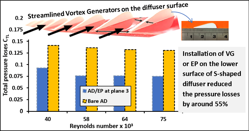
Gas Turbines are among the most important energy systems for aviation and thermal-based power generation. The performance of gas turbine intakes with S-shaped diffusers is vulnerable to flow separation, reversal flow, and pressure distortion, mainly in aggressive S-shaped diffusers. Several methods, including vortex generators and energy promoters, have been proposed and investigated both experimentally and numerically. This paper compiles a review of experimental investigations that have been performed and reported to mitigate flow separation and restore system performance. The operational principles, classifications, design geometries, and performance parameters of S-shaped diffusers are presented to facilitate the analysis and understanding of the influence of each mitigation method on flow enhancement in S-shaped diffusers. The influencing design parameters on the performance of the S-shaped diffuser and the findings achieved by various experimental investigations are discussed and compared. The review concludes that reducing the intake length reduces the size and weight of the gas turbine, leading to a higher power-to-weight ratio. However, the main challenge in shortening the S-shaped diffusers is the flow separation in the high-curvature section, which must be prevented to maintain high performance. Prevention can be achieved through flow control methods, which are categorized into passive and aggressive methods. The static pressure recovery coefficient, total pressure loss coefficient, ideal static pressure coefficient, distortion coefficient, and skin friction coefficient are the primary performance evaluation and comparison parameters between the experimentally investigated mitigation methods. The new trend in S-shaped diffuser studies includes the integration of computational and data-driven methods.Graphic Abstract
Keywords
After the prototype experiment in 1937, gas turbines (GT) have become widely used as aeroengines in aircraft propulsion due to the large power-to-weight ratio compared to other power engines. Since then, the GT aeroengines’ performance has been considerably enhanced over four generations of development, and the thrust-to-weight ratio has increased from 3 to 10, making it one of the most efficient energy and power engines. The GT in propulsion applications is called an “airbreathing” aeroengine. The GT in thermal power plants based on gas fueling is called “gas power plant”, or “gas-fired power plant”. The main components of the GT are the air intake, the compressor, the combustor, the turbine, and the exhaust nozzle. The intake is an important component of an air-breathing aeroengine. Intake is the first part of the aeroengines that controls the mass flow rate supplied to the next parts of the GT. In aeroengines, in particular, air mass flow rate through the engines is a highly influential parameter on both the generated thrust-to-power and fuel consumption. High capability to control the air mass flow rate depends on the air intake design and performance. Such intake requirements could be achieved via a proper geometry design optimization and control during the flight regimes and maneuverability. The design of the GT intakes depends on the flow regimes, subsonic or supersonic. In the subsonic aeroengines, the intake has fixed geometries. In the supersonic aeroengines, the intake has a moving spike that can move forward and backward to control the flow area and the shock wave(s) structure [1–3]. However, the pressure recovery and efficiency of the intake section significantly impacted the GT performance. The most common types of air intake for the GT are equipped with an S-shaped diffuser. It is preferred due to space restrictions and design compatibility. Fig. 1 shows a typical commercial GT aeroengine with a highlight of the S-shaped diffuser at the air intake section.
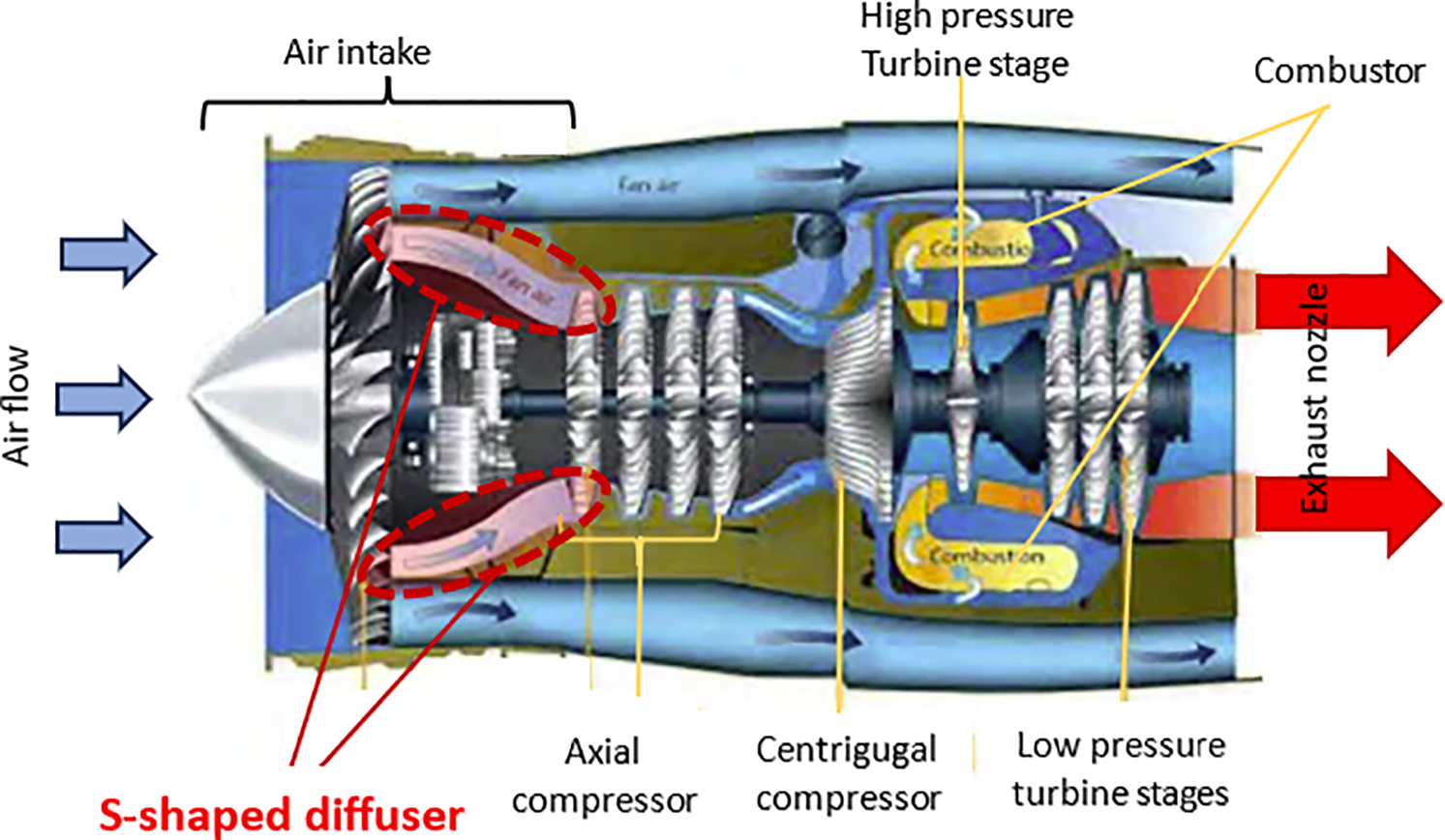
Figure 1: Typical commercial gas turbine engine with S-shaped diffuser
This review aims to discuss the design types and the performance manipulation due to the design change in the S-shaped diffuser illustrated in the intake section of the aeroengine and study all the explain the factors that affect the performance. Additionally, the review discusses the reported experimental and practical application attempts to improve the flow structure and the S-shaped diffuser performance. A comparison is conducted among various experimental studies using different performance indicators to identify the most effective methods for enhancing performance.
In a general sense, the diffuser is a flow device that increases the static pressure at the outlet at the expense of the fluid’s kinetic energy, leading to a reduction in the velocity of a moving fluid.
In application-wise, S-shaped diffusers are used in the passages of the centrifugal pumps, in the steam guide passage of the steam turbine, and in the gas turbines. They are mainly used in intakes of aeroengines running commercial and military aircraft. In the aeroengine application, the main purpose of an S-shaped diffuser is to transfer the air from the intake section to the turbine section with prespecified flow conditions to secure smooth operation of the turbine section. The S-shaped diffusers are qualified for use in gas turbines, as the axial length of the duct could be shortened to reduce the weight penalties associated with engine length. For example, the interconnecting compressor duct of the twin-spool Pratt & Whitney PW4000 represents approximately 6.5% of the overall engine length [4]. Also, the S-shaped diffuser has been used in military aircraft like the F-16, F-18 light combat aircraft. The S-shaped duct is also used as the inlet of the subsonic cruise missiles.
In design-wise, diffusers may have radial, axial, or curved shapes depending on the geometrical design and the applications in various engineering equipment. The S-shaped diffuser is a curved type. Flow enters the diffuser through the inlet area, flows through the curved conduit, and exits from the outlet of a larger area with lower velocity and higher pressure. The inflection in the curvature along the flow direction results in a more complicated flow structure and causes strong pressure-driven streamwise vortices, as well as flow distortion [5–7]. The compact S-shaped diffuser design must effectively suppress the flow reversal and separation. Tournier et al., 2006 [8] showed that during maneuvers of the cruise missile, both the external flow interaction with the forebody can create drastic losses. Separation can occur inside the inlet duct and generate compressor face distortion, leading to instabilities, especially in compact air inlets. There is interest in improved S-shaped diffuser designs to enhance turbomachinery performance. The importance of enhancing the performance of the S-shaped diffuser, and in turn the GT performance, is the large adoption of advanced aeroengines in modern fighters and commercial air transport planes. Many studies on S-shaped diffusers are available in the literature because they are an engineering geometry challenge to understand.
2.1 Critical Engineering Constraints in S-Shaped Diffusers
Literature demonstrates many attempts to enhance the S-shaped diffusers used in the aeroengines. However, the performance enhancement methods of S-shaped diffusers are hampered by geometrical design factors. The alteration in the diffuser geometry leads to early flow separation, reversal flows, and high turbulence. Those consequences in the flow structure reduce pressure recovery and flow uniformity. The central engineering challenge in this dilemma is to balance the requirement for a compact aeroengine design with the S-shaped diffuser aerodynamic consequences.
2.1.1 Flow Reversal and Separation
A main setback of reducing the length of the S-shaped diffuser is the high curvature in the bend zone that causes boundary layer detachment from the inner wall. The high curvature leads to an earlier flow detachment and large flow separation, resulting in an adverse pressure gradient, and consequently, the kinetic energy within the flow is inadequate to overcome it, leading to separation. The flow separation significantly reduces the pressure recovery and consequently reduces the efficiency of the diffuser by impeding the conversion of kinetic energy into static pressure. In addition, shortening the S-shaped diffusers, aiming compact aeroengine design, imposes a tradeoff between space and performance due to the flow separation [6,7].
2.1.2 Vortices and Secondary Flow
The large pressure gradient in the flow inside the S-shaped diffuser causes the fluid to turn twice, generating a secondary flow. Consequently, the backward motion of the fluid particles is subjected to centrifugal forces, creating a transverse pressure gradient. The low-momentum fluid travels from the boundary layer towards the inner wall, causing the formation of counter-rotating vortices. Those vortices affect the flow structure at the S-shaped diffuser outlet, causing substantial flow non-uniformity and high flow distortion. On the other hand, the vortices and secondary flow impose high turbulent mixing and kinetic energy dissipation, which increase the total pressure loss.
2.2 Normal and Aggressive S-Shaped Diffusers
The S-shaped duct must be as short as possible due to cost and weight considerations. It is possible to shorten the duct simply by reducing its length, but the risk of separation increases, and losses rise. Fig. 2 illustrates the effect of shortening the length of a normal S-shaped diffuser to create an aggressive S-shaped diffuser on the separation by reducing static pressure recovery and shifting the separation upstream of the flow with early flow separation. The larger separation region results in increased pressure losses and decreases the S-shaped diffuser’s performance [7–9].
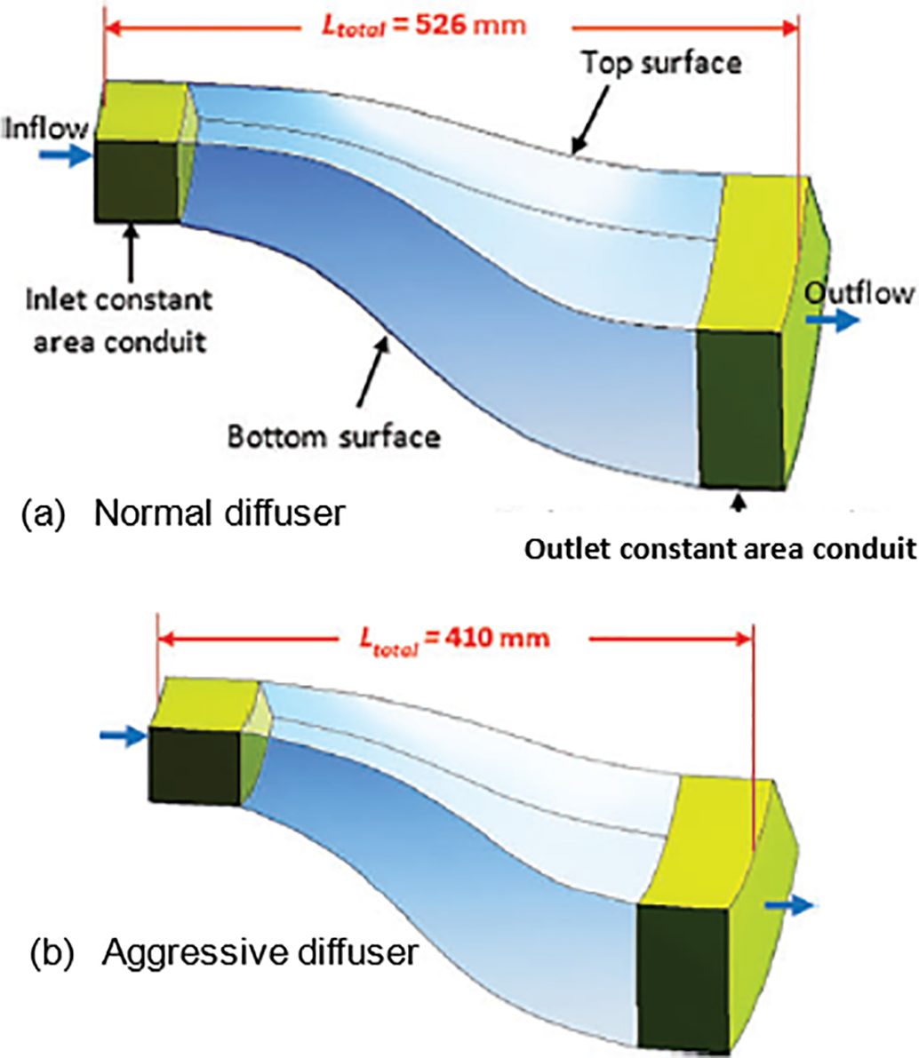
Figure 2: Alteration of the normal to an aggressive diffuser criterion. (a) Normal S-shaped diffuser and (b) Aggressive S-shaped diffuser [6]
The compact, S-shaped inlet designs must effectively suppress flow separation and the development of secondary flows. This suppression can be achieved using various flow modification techniques, such as active flow control by blowing [7,9–11], micro and synthetic jet [12–14], passive flow control [8,15–18], and many others, or a hybrid combination of both active and passive flow control [19].
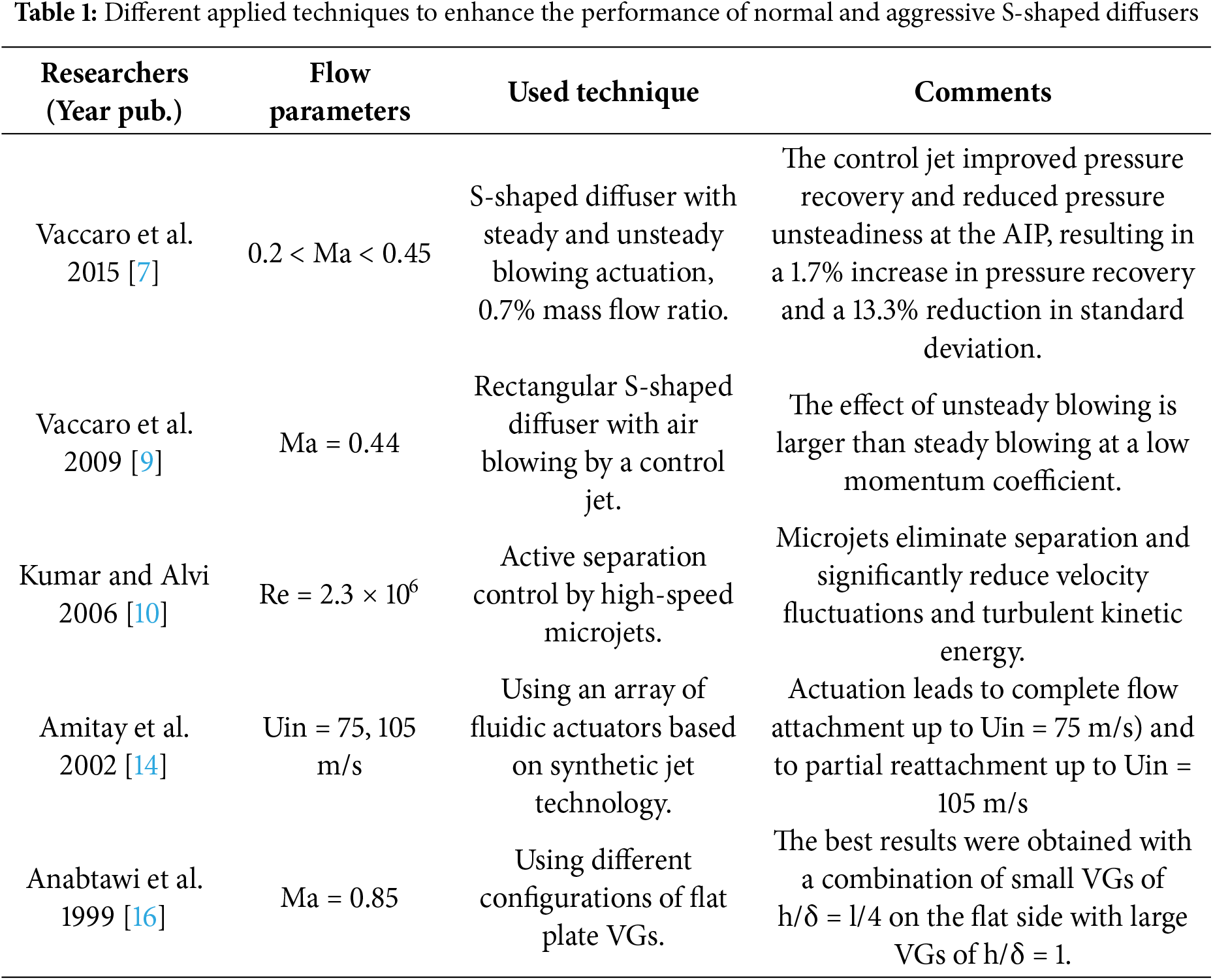
The second strategy is passive flow control using vortex generators (VGs), which is reported by Vakili et al. [15], Anabtawi et al. [16], Anderson et al. [17], and Lee and Liou [18]. The VGs model is available in two configurations: micro-ramps or micro-vanes. Table 1 summarizes the various techniques employed to enhance the performance of both normal and aggressive S-shaped diffusers.
Over the years, various options have been explored to control flow separation and enhance the performance of the S-shaped diffusers. Few attempts have been made to summarize the work done in the field of S-shaped diffusers, but truly little, maybe none, has been done as in this paper to review different flow control techniques. This paper provides an in-depth review of experimental investigations into the flow improvement of the S-shaped diffuser for GT aeroengines. Additionally, explaining and discussing fluid dynamics within the S-shaped diffuser and the design parameters that affect its performance. In addition, performance parameters and their optimization methods used for performance evaluation are presented. Section 5 discusses and compares the active, passive, and hybrid flow control approaches to enhance the performance of S-shaped diffusers.
2.3 Performance Parameters of S-Shaped Diffuser
The performance evaluation of the S-shaped diffuser is usually performed in various indicators like static pressure recovery coefficient CPR, Ideal static pressure recovery coefficient CPSI, wall static pressure recovery coefficient CWPR, total pressure loss coefficient CTL, and distortion coefficient DC(60°), or DC(45°), [4–6].
2.3.1 Static Pressure Recovery Coefficient, CPR
This coefficient represents the magnitude of kinetic energy converted into pressure energy due to the diffusing action at any location along the S-shaped diffuser. This is a suitable term for nondimensionalized quantities when quoting diffuser performance, because the dynamic inlet head is usually larger than the exit, resulting in a larger number. Additionally, the inlet conditions are likely to be more uniform than the exit conditions, providing a more reliable reference value. The equation that represents the static pressure recovery is:
2.3.2 Ideal Static Pressure Recovery Coefficient, CPSI
The inlet and exit flows are completely uniform. The total pressure at the inlet would equal that at the exit (pin = pout) when the flow through a diffuser was frictionless. By applying the continuity and momentum principles and assuming incompressible flow, Eq. (1) could be rearranged to get the CPSI as in Eq. (2):
where the arias Ain and Aout are the inlet and outlet areas of the diffuser, respectively.
2.3.3 Wall Static Pressure Recovery Coefficient, CWPR
The following equation represents the wall static pressure coefficient.
2.3.4 Total Pressure Loss Coefficient, CTL
It measures the total pressure loss as a proportion of the mean inlet dynamic head due to viscous forces and turbulent mixing. The total pressure loss coefficient is defined by Eq. (4).
2.3.5 Distortion Coefficient, DC(60°) or DC(45°)
DC(60°), sometimes referred to as DC(45°) by some researchers, is one of the important parameters for evaluating the performance of an S-shaped diffuser. It represents the magnitude of the difference between the maximum and the minimum total pressure divided by the average total pressure at the outlet plane of the diffuser.
where all the pressures in Eq. (5) are the ones at the outlet of the diffuser.
2.3.6 Skin Friction Coefficient, Cf
The skin friction coefficient is the ratio of skin shear stress on the surface to the dynamic pressure of the free stream. The equation represents the skin friction coefficient.
The performance evaluation parameters, Eqs. (1) to (6) represent dimensionless groups that provide sufficient analytical linkage between the design and operational parameters. The presented analysis of the experimental results in terms of performance parameters at various Reynolds numbers and/or various Mach numbers represents a nondimensionalized parametric sensitivity analysis. Design optimization of S-shaped diffusers through parametric sensitivity analysis features the complex interplay between geometric and operational factors that impact flow structure and the diffuser performance. The main performance optimization goals are maximizing total pressure recovery (the ratio of outlet to inlet total pressure shown in Eq. (1)) and minimizing flow distortion, DC(45°) or DC(60°), presented in Eq. (5).
Not all the parameters shown in Eqs. (1) to (6) have been used as performance enhancement indicators since they have the researchers adopted not all. The most important performance parameters, described in Eqs. (1), (4), and (5) are commonly adopted in the literature to indicate the performance improvement. Consequently, they are mostly adopted in the current review as evaluation and comparison indicators of different experimental research results.
3 Fluid Dynamics of S-Shaped Diffuser
Understanding the basics of flow dynamics in S-shaped diffusers. The turning flow dynamics have three fundamentals: the distribution of radial pressure variation, the generation of pressure-driven secondary flow, and the occurrence of separating and recirculating flow [20]. The centrifugal force by fluid motion through the curvature of the turning flow is balanced by the variation of radial pressure increasing from the inner to outer bend, as shown in Fig. 3a. This variation of radial pressure creates a low-pressure zone at the bottom surface of the first bend with appropriate beginning pressure gradients and adverse gradients towards the outlet. On the contrary, a high-pressure zone develops at the top surface of the first bend, characterized by starting adverse gradients and appropriate gradients at the bend outlet. The displaced flow encounters a higher-pressure zone, which redirects the flow from the top surface to the lower-pressure zone at the bottom surface along the sidewalls. The process resulting in the secondary flow generates a pair of counter-rotating vortices in the streamwise direction, as shown in Fig. 3b. Fluid with low energy is accumulated at the end of the first bend on the bottom surface because of the secondary flow motion. The area is sensitive to flow separation. Fig. 3c shows that the low-momentum flow encounters the adverse pressure gradient at the bend outlet.
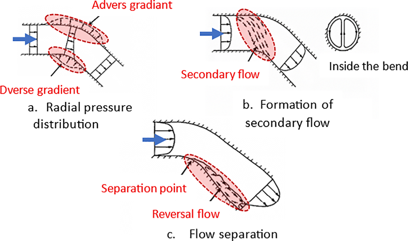
Figure 3: Turning flow in a single bend
It can be concluded that boundary layer separation and reversal flow on the casing are the dominant operational factors affecting the air intake S-shaped diffuser. Therefore, most studies suggest the elimination, or at least the reduction, of flow separation through various flow control techniques. Implementing passive, active, and hybrid flow control enhances flow and improves performance. However, each of these flow control techniques has its advantages and disadvantages.
4 Design Parameters of the S-Shaped Diffuser
S-shaped diffuser flow fields become increasingly complex as adverse pressure gradients in diffusing passages increase. The S-shaped diffuser design relies on geometrical parameters, including the area ratio, AR, the turning angle, θ, the turning radius, R, and the passage cross-section [21]. The S-shaped diffuser has the geometrical parameters and notations outlined in Fig. 4. These parameters have a significant effect on the performance of the S-shaped diffuser, particularly through the onset of flow separation and the extent of the flow separation zone, which in turn affects the magnitude of pressure recovery, pressure loss, and flow uniformity at the outlet plane. The previous investigations and analyses of the design parameters are presented and discussed in the following subsections.
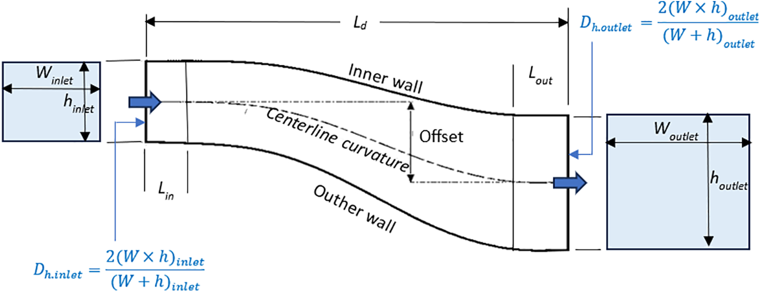
Figure 4: The notations and geometrical design parameters of the S-shaped diffuser
4.1 Area Ratio and Aspect Ratios
The area ratio (AR) of the S-shaped diffuser represents the value of the outlet plane area to the inlet plane area, while the aspect ratio (AS) is the radial height/lateral width at the inlet, Eq. (7).
Many researchers studied the effect of changing AR on the performance of an S-shaped diffuser. Asghar et al. [22] evaluated the performance of the S-duct diffuser with three variants of AR and AS, where (i) AR = 1.57, AS = 2.0, (ii) AR = 1.8, AS = 1.5, and (iii) AR = 1.8, AS = 2.0 at Mach numbers (Ma) of 0.8 and 0.85. The results show CTL loss of 6% to 7% for various tested S-duct diffusers. The effect of AS on the CTL was noted, but it cannot be determined which trend indicates better performance with an AS. However, an increase in AR resulted in a slight decrease in CPR. In addition, the radial distortion due to increased AS for configurations AR 1.57 and AR 1.8 with a flow Mach number of 0.80 decreased due to better pressure recovery, CPR close to the bottom wall.
4.2 Turning Angle and Turning Radius
The other key geometrical parameter is the turning angle, θ. A study of S-duct flow dynamics on square section S-shaped duct with two different turning angles of 45°/45°, and 35.3°/35.3.6°, and different turning radii of 280 mm and 242.5 mm was conducted by Jessam et al. [23], as shown in Fig. 5. The higher turning angles result in greater measured pressure differences between the outer and inner surfaces. The higher adverse pressure gradients were measured at the two inner duct convex walls than at the two outer concave walls. The flow separation has been detected at the first bend of the inner convex wall for all three ducts. The study concluded that the slight distortions indicated the locations of flow separation in wall pressure distributions obtained from pressure taps.
Figure 5: Geometry of the S-duct with different turning angles and different turning radius [23]
Anand et al. [24] experimentally studied the effects of turning angles of 15°/15°, 22.5°/22.5°, and 30°/30° in the AR 1.9 circular S-bend diffuser. The decrease in overall CPR, from 0.45 to 0.35, was demonstrated with increasing turning angle. It was concluded that the CTL for all the diffusers is nearly the same and appears to be independent of the angle of turn. The flow distribution is more uniform at the exit for the higher-angle turn diffusers.
4.3 Cross-Sectional Types of S-Shaped Diffusers
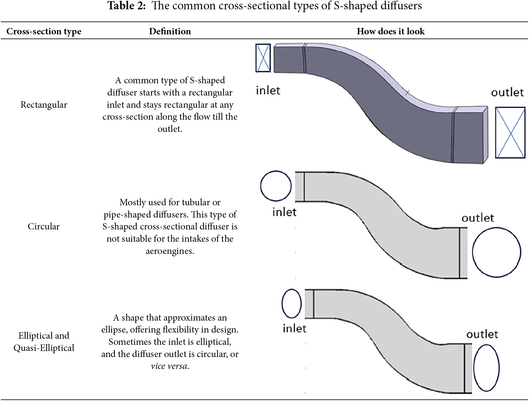
The investigated intake S-shaped diffuser could be found in various cross-section geometries. It might be circular/elliptical [25,26], square [27], square at the inlet transitioning to rectangular at the outlet plane [28], rectangular [29], and rectangular or half-circle at the inlet transitioning to circular at the outlet [30,31], and sometimes a circular inlet and Fishtailed outlet. The design requirement rules the selected cross-section shape, and it is determined by design parameters like the area ratio and air intake geometry in the aeroengine. Table 2 shows the common types of S-shaped diffuser cross-sections.
In addition to the standard cross sections, there are special designs of the cross-sectional shape of the S-shaped diffuser. Ibrahim et al. [31] investigated the effects of curvature and cross-sectional shape on the performance of an S-shaped diffuser in the aeroengine of the F-5 Tiger fighter jet with different cross-sectional geometries.
Different geometries were evaluated, including a duct with a circular cross-section and a straight duct with a similar cross-sectional transition subsonic diffuser, as shown in Fig. 6. The results show a 0.5% increase in CPR and a 15% decrease in DC(60°) of the baseline intake duct compared to the constant circular cross-sectional duct. The straight duct is adopted in the Northrop F-5 supersonic light fighter aircraft family, which was initially designed in the late 1950s by Northrop Corporation of the USA. The straight cross-sectional transition used in the F-5 Tiger fighter jet intake resulted in a 2.1% increase in CPR and an 86% reduction in DC(60°) compared to the baseline intake.
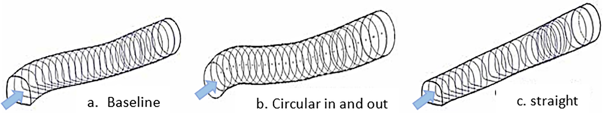
Figure 6: Tested geometries of the aeroengine of the F-5 Tiger fighter jet. (a) Baseline configuration, (b) Circular cross-section configuration, (c) Straight centerline configuration [31]
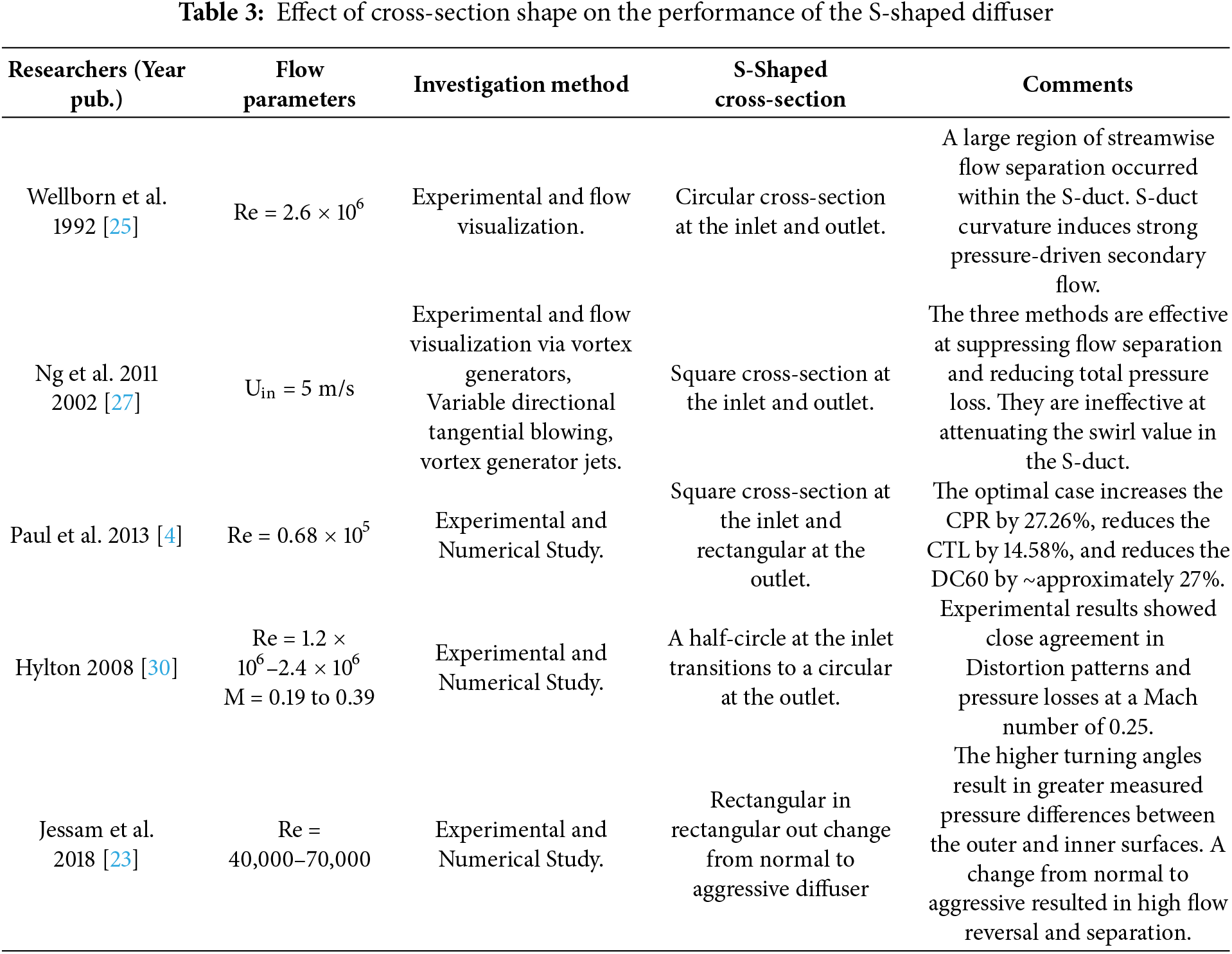
Generally, the geometric parameters in aerospace applications are usually restricted to an S-shaped diffuser design. Thus, the design optimization focuses on controlling and reducing the flow separation initiated at the convex surface of the first bend, which occurs with low-energy flow. Table 3 summarizes the effect of different cross-sectional shapes of the S-shaped diffuser on the performance.
On the other hand, Jiang et al. [32] performed a recent experiment to investigate the flow characteristics inside an S-shaped diffuser at a range of Mach numbers from 0.06 to 0.15 at various lengths of upstream and downstream extensions. The duct entrance radius was 102.1 mm, and the exit radius was 125.7 mm. They concluded that the influences of the upstream and downstream extensions on the flow structure inside the S-shaped diffuser are more than the influence caused by the flow velocity.
As mentioned previously, various techniques have been applied to enhance the performance of S-shaped diffusers, including active flow control, passive flow control, and hybrid flow control.
5.1 Active Flow Control (Air Blowing or Suction)
Active flow control aims to alter a natural flow or redirect it into a more desirable path. Active flow control mainly involves adding auxiliary power into the flow. These devices are used in S-shaped diffusers, mainly with four Coanda-type (steady or unsteady) Ejectors, Vortex Generators, Jets, Microjets, and Synthetic Jet Actuators. It is used for flow control via three known methods:
• Addition of high-momentum fluid.
• Removal of low-momentum fluid.
• Redistribution of the momentum across the boundary layer.
5.1.1 Coanda Type (Steady or Unsteady) Ejectors
Coanda ejectors are a type of active flow control that can be used to improve the flow inside an S-shaped diffuser. The injector relies on the Coanda effect to cause the injection jet to adhere to the wall as it progresses downstream. The injection stream should be positioned close to and tangential to the wall; otherwise, it would shed a wake and potentially enhance the separation. The injection stream would maximize the oscillatory component’s ability to interact with the boundary layer, thereby weakening or eliminating separation and improving pressure recovery at the AIP [33].
Luers [34] employed this technique to modify an Unmanned Combat Air Vehicle (UCAV) with 3D geometry at high subsonic conditions. The periodic injection, Coanda injection, was introduced near the separation point. After adjusting several parameters, the momentum coefficient, injection slot position, injection angle, and injection frequency, periodic separation point injection improved pressure recovery and significantly reduced distortion. When 2% of the inlet mass flow rate is injected, an increased total pressure recovery of 3.75% in the upper quadrant, the distortion was reduced by over 60%.
Vaccaro et al. [7] studied flow control in a short S-shape diffuser with a rectangular cross-section, experimentally and numerically, using a two-dimensional tangential control jet, specifically a Coanda-type injector. The effect of steady and unsteady blowing actuation (0.7% mass flow ratio) at a freestream Mach number of 0.44 was studied. The Coanda-type injector was distributed tangentially to the surface at the beginning of the upstream turn, as shown in Fig. 7.
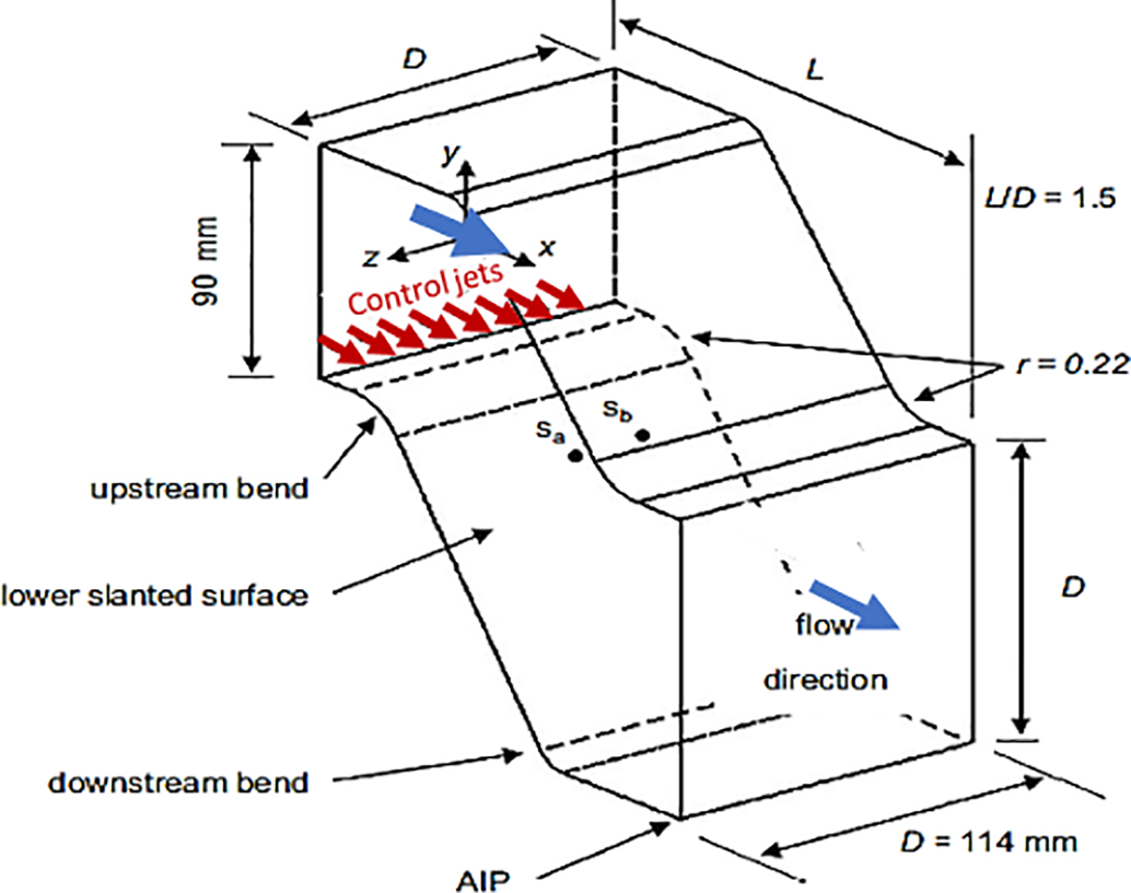
Figure 7: Inlet duct and control jet schematic [7]
Fig. 8 shows the effect of the control jet on the flow separation zone reduction through experimental and numerical investigation. The Coanda-type injector had the effect of tilting the core flow inside the S-duct down toward the lower surface, and then the core flow stagnated near the AIP. The two-dimensional tangential control jet improves pressure recovery at the AIP by 13.3%. Also, the energy content was eliminated from the distinct unsteady fluctuations that characterized the baseline flow field.
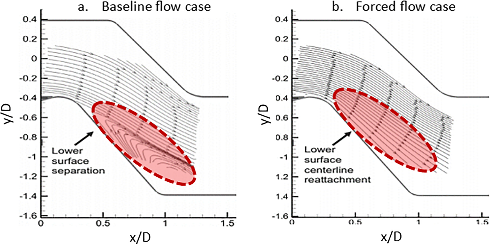
Figure 8: Comparison of the experimental flowfield measurements as velocity vector lines close to the centerline plane: (a) experimental results for baseline flow field, (b) experimental results for forced flow field. (modified from Vaccaro et al. [7])
Table 4 summarizes the effect of applying active flow control, steady and unsteady Coanda-type ejectors, on the performance of the S-shaped diffuser.
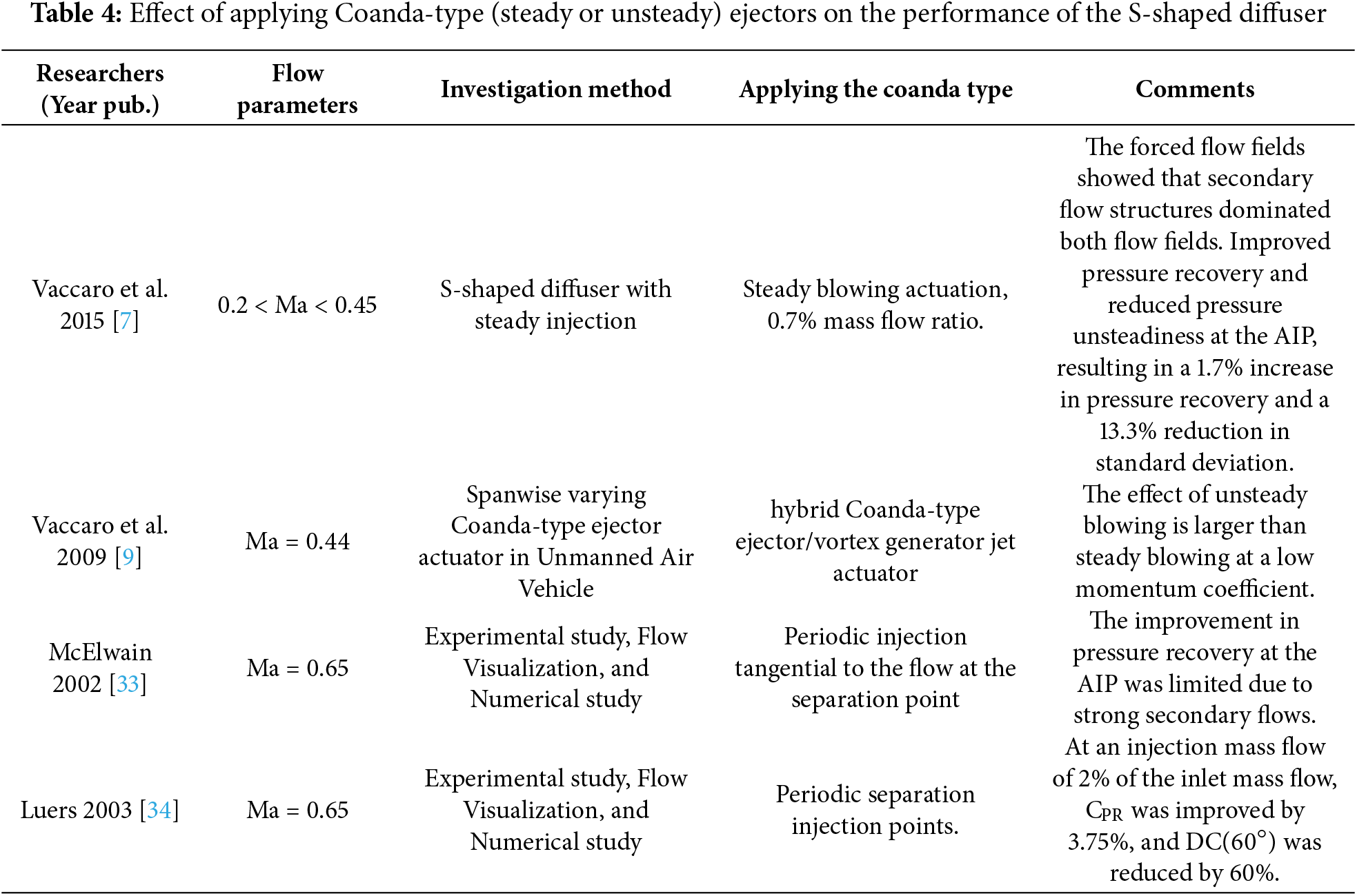
On the air suction, Debiasi et al. [35] investigated the effect of injecting and suctioning 2% on the mainstream in an S-duct of M2129 geometry, both experimentally and numerically using the shear stress transport (SST) model. Injecting 2% of the main flow before the first bend of the S-duct and then suctioning 2% at the second bend is an effective way to control flow separation, as shown in Fig. 9. The experimental and numerical results show that the total-pressure distribution of the controlled flow case is characterized by a higher overall pressure compared to the uncontrolled cases.
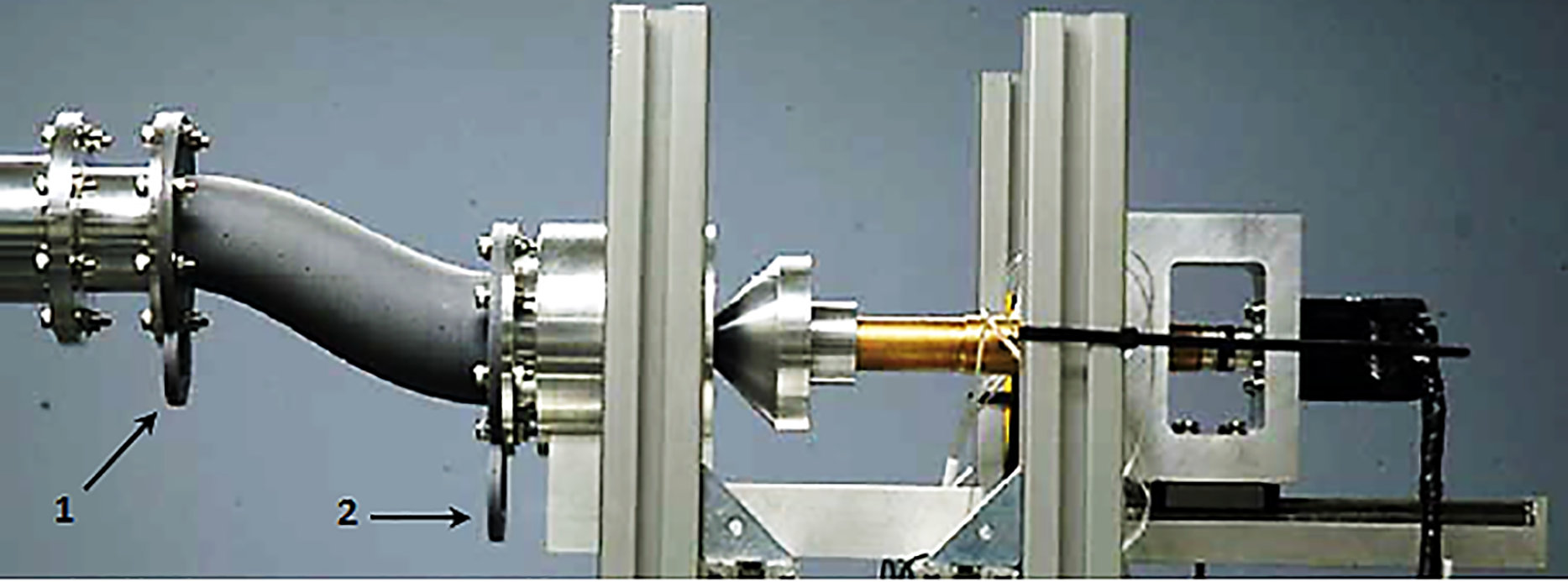
Figure 9: Experimental apparatus with injection port (1) and suction port (2) of S-duct used by Debiasi et al. [35]
Furthermore, Zhang et al. [36] have experimentally and numerically studied the flow control and aerodynamics in a 2D supersonic S-shaped inlet duct. The experiments were performed with inlet Ma of 1.5, 2, 3, and 4. They evaluated the bare diffuser and the diffuser with suction air flow control. They found that the diffuser performance with suction is higher compared to the diffuser without suction. The total pressure recovery coefficient improves by 2%–3% due to air suction, while the outlet Ma decreases by about 0.03 compared to the inlet Ma. They realized that flow separation is mainly concentrated on the sidewall in the upstream of the diffuser. Accordingly, sidewall suction is more effective in eliminating the separation and enhancing the flow structure.
The vortex generator jets (VGJs) are jets that pass through a wall and enter a crossflow, creating a dominant vortex in the stream of flow and remaining embedded in the boundary layer over the wall. The jet passes through a circular hole (the jet hole) of diameter in a wall over which the crossflow produces a turbulent boundary layer. Two factors could characterize the VGJ. The first factor is the velocity ratio between the jet and the crossflow. The second factor is the pitch and skew angles, Φ and θ, respectively. The angle between the ellipse’s major axis and the streamwise direction is referred to as the skew angle, θ, and the angle between the jet-hole centerline and the wall is designated as the pitch angle, Φ [37].
Johnston [38] explained the application of VGJ as a separation flow control and unsteady vortex generator jets. The pulsing was observed to provide more efficient use of the jet fluid. Additionally, the possibility of better control was observed when using unsteady vortex generator jets compared to steady vortex generator jets. Similarly, Sullerey and Pradeep [39] achieve an improvement in S-duct diffusers by using VGJ. The Experiments were conducted with uniform flow and distorted flow. The velocity ratios (jet velocity to freestream velocity) and VGJ skew angles were varied to optimize the performance of the S-duct diffuser. It was observed that using tapered-fin vortex generators to control flow separation gives better results than those obtained by employing VGJs alone on the diffuser wall.
The effectiveness of vortex generator jets in controlling secondary flows was investigated on an S-shaped diffuser with a rectangular cross-section by Sullerey and Pradeep [40]. Tapered fin vortex generators were employed in addition to vortex generator jets with an inflow distortion case to control flow separation on the wall with inflow distortion, as shown in Fig. 10. The experiments were conducted under both distorted and uniform inflow conditions. The diffuser’s performance evaluation was conducted in terms of static pressure recovery and distortion at the exit of the S-duct. Different velocity ratios of 1.0, 1.2, and 1.5, different skew angles of 90°, 110°, 130°, 135° and 140° were employed for both experimental cases. The use of vortex generator jets with uniform inflow reduces the flow distortion and total pressure loss coefficients by more than 30%. For distorted inflow conditions, using a combination of passive flow control (tapered fin vortex generators) with the vortex generator jets reduces total pressure losses by 25%. They concluded that the passive flow control by tapered-fin VGs, in conjunction with active flow control, VGJs, yields higher performance than that obtained with tapered-fin VGs alone.
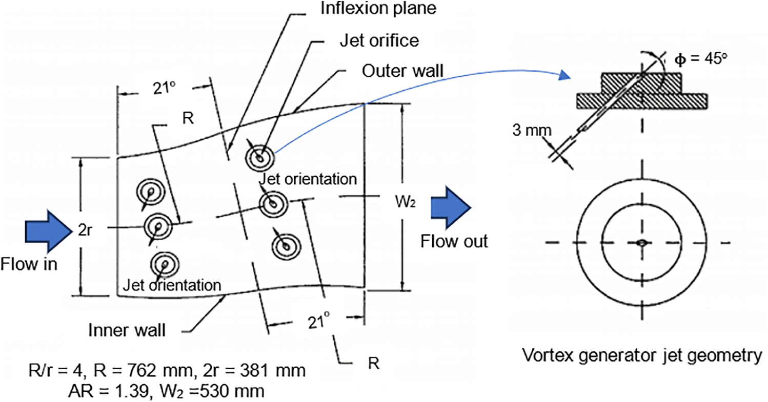
Figure 10: S-duct diffuser, vortex generator jet VGJ, and VGJ flow arrangement (reproduced from [40])
Pradeep and Sullerey [41] enhanced the performance of the S-duct diffuser by controlling secondary flow and separation using VGJ. They studied two different diffuser geometries: the first was a circular diffuser, and the second was a rectangular diffuser transitioning to a circular one. The use of vortex generator jets in circular and transitioning diffusers improves performance by approximately 22% in flow distortion and 26% in total pressure loss coefficients. Also, the total pressure loss coefficient was reduced by about 48% in the rectangular diffuser and by around 30% in the transitioning and circular diffusers.
Sullerey et al. [42] investigated the performance of an S-duct intake using circular VGJs with an internal diameter of 4 mm placed at a pitch angle of 45° and a skew angle of 135°. Performance was studied with different velocity ratios, jet location, and jet numbers. The best control configuration has improved performance by approximately 35% in terms of average static pressure recovery, resulting in a significant reduction in outflow swirl, a 10% decrease in distortion intensity, and enhanced total pressure recovery.
Microjets are a type of active flow control that can control flow separation inside an S-shaped diffuser. Microjets have been experimentally employed to control boundary-layer separation in an adverse pressure gradient within an S-shaped diffuser [10]. The 60 microjets equipped with 400 μm arrays were oriented vertically concerning the freestream. The effectiveness of microjets was clear, as they eliminated separate flow regions. This elimination led to an increase in the momentum of the flow near the surface, ultimately enhancing performance.
The blowing technique with separated holes, derived from the entrance profile, has been applied to eliminate the flow separation created by the boundary layer [11]. This technique was employed with various flow control configurations, using a Mach number of 0.064 for the streamwise velocity and a free stream velocity of 0.039. The separated holes were injected at the head of the ramp. They directed the flow parallel to the ramp in the first configuration and induced a secondary angle to direct the flow towards the sidewalls in the second configuration. Experiments were conducted with different velocity ratios and different flow control configurations (straight step, fanned step, straight ramp, fanned ramp). The results indicated that the fanned flow control configurations perform slightly better than the straight configurations.
5.1.4 Synthetic Jets Actuators
A synthetic jet flow is a type of jet flow made up of the surrounding fluid. Synthetic jets are generally formed by a flow that moves back and forth, involving the periodic ejection and suction of fluid through a small opening [43–45]. Synthetic jet modules have also been widely researched for controlling airflow. Problems in applying the technology include weight, size, response time, force, and complexity of controlling the flows [46].
An active flow control, a piezoelectric synthetic jet, and a passive flow control device, micro vortex generators were used to control the flow in an adverse pressure gradient with secondary flows in the 15-inch Low-Speed Tunnel at NASA Langley Research Center [47]. The wall static pressure performance indicator is used for evaluating the effectiveness of these flow controllers. The final results show that piezoelectric synthetic jet actuators must have sufficient velocity output to produce strong longitudinal vortices if they are to be effective for flow control; however, the micro vortex generators effectively controlled the flow environment in the presence of an adverse pressure gradient.
Two fluidic actuators based on synthetic jet technology have been designed to produce partially or completely flow separation control in a two-dimensional serpentine duct model. In the first configuration, the hinged diffuser surface (upper surface) is open to 14°, and suction is used to maintain attached flow on that surface, resulting in a separation bubble on the opposite (bottom) surface, as shown in Fig. 11a. The second configuration is a serpentine duct in which the flow surfaces are parallel, and a separation bubble forms on the expanding surface, as displayed in Fig. 11b. This technology was demonstrated by Smith et al. [48], Amitay et al. [49], Amitay et al. [50], and Amitay et al. [51], who used fluidic actuation based on synthetic-jet technology to reduce the flow separation.
Figure 11: Two configurations of a two-dimensional diffuser setup [47]
The synthetic jet array, shown in Fig. 12, was positioned downstream of the separation. The experiments have been conducted with Uav.in = U∞ = 75 m/s and 105 m/s. The final findings suggested that more effective control of internal flow separation can be achieved by increasing the jet strength and application of spanwise uniform actuation.
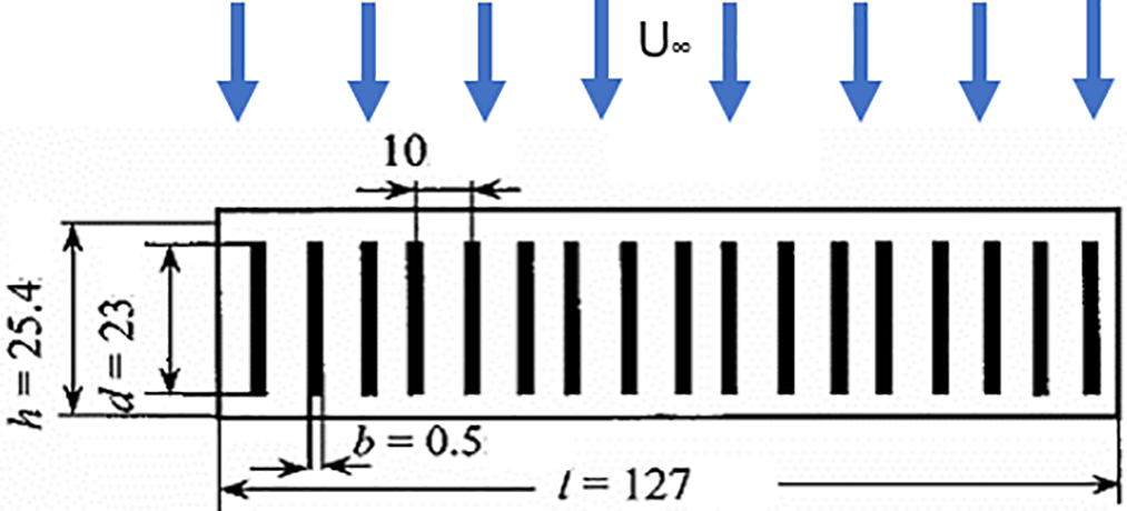
Figure 12: Synthetic jet array configuration [50]. Two configurations of a two-dimensional diffuser setup. a. [46]. a. The upper surface is open to 14°, and suction is used to maintain attached flow, b. A serpentine duct in which the flow surfaces are parallel
Removing the separation that occurs in the curvature and achieving a less distorted flow at the outlet of the duct is the main challenge of flow control in a high-curvature S-shaped air intake diffuser. For this purpose, a zero-net-mass-flow (ZNMF) jet, similar to a synthetic jet, has been used to investigate a two-dimensional model of an S-shaped air intake diffuser [52]. Experiments were conducted in the symmetry plane of the duct at a Reynolds number of Re = 8 × 10⁴ using PIV measurements. The ZNMF jets have a round section with a diameter of d = 0.5 mm and a pitch of c = 3 mm. They are organized in a row of 500 mm width in the spanwise direction, centered around the duct’s symmetry plane. Five identical rows of jets were installed in the lower wall of the duct, as in Fig. 13.
Figure 13: Schematic view of the rows of ZNMF jets [52]
5.2 Passive Flow Control (Vortex Generators)
Passive flow control VGs can be defined as small vane-type sections fixed on critical regions to eliminate or reduce undesired flow, like upstream vortices, wake disturbances, and upstream shock-wave boundary-layer interactions [53]. Vortex generators are used in two different ways, which are:
• To direct secondary flows.
• To reduce or eliminate boundary layer separation by transporting high momentum flow into low momentum boundary layer flow.
The VGs generate a streamwise vortex when immersed in a crossflow. The size of the VGs depends on the thickness of the boundary layer. The VGs are typically positioned just outside the edge of the boundary layer to maximize the interaction between the shed vortex and the low-momentum fluid. The interaction modifies the boundary layer fluid motion by bringing momentum from the outer flow region into the inner flow region of the wall-bounded flow. Through this transfer of energy, the momentum in the near-wall region increases. At the same time, the boundary layer thickness decreases, which in turn delays the separation and shifts the separation point downstream. This enables the expanded airflow to persist proportionately longer, the flow velocity at the separation point to decrease, and the static pressure to increase.
The performance of installed VGs is a function of three categories of variables:
• The inflow conditions, like the inlet mass flow and the Reynolds number.
• The aerodynamic characteristics are associated with the inlet duct.
• The design parameters related to the geometry, arrangement, and position of the VGs within the inlet duct itself [53].
Many researchers have performed experimental investigations on S-duct models with passive flow controllers and studied the effect of VGs on the S-shaped diffuser’s performance enhancement. The outlines of each type are shown in Fig. 14.
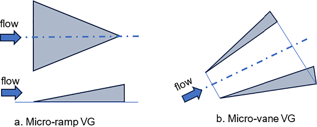
Figure 14: Common types of vortex generators used to control the flow separation. (a) Micro-ramp VG, (b) Micro-vane VG
Paul et al. [4] investigated a rectangular S-duct diffuser in different combinations of a passive-type submerged-vortex generator to establish its effectiveness in improving the flow pattern. Fig. 15 shows the geometry of the implemented VGs and the three combinations of submerged VGs. The combinations of VGs are evaluated at three installation planes. The experimental and numerical results demonstrate that the performance of the S-shaped diffuser was enhanced by applying VGs compared to the bare diffuser, as illustrated in Fig. 15. The best case showed an improvement of CPS by 27.26% and a reduction in CTL by 14.58%, DC(60°) by approximately 27%, and the non-uniformity index by approximately 24.58%.
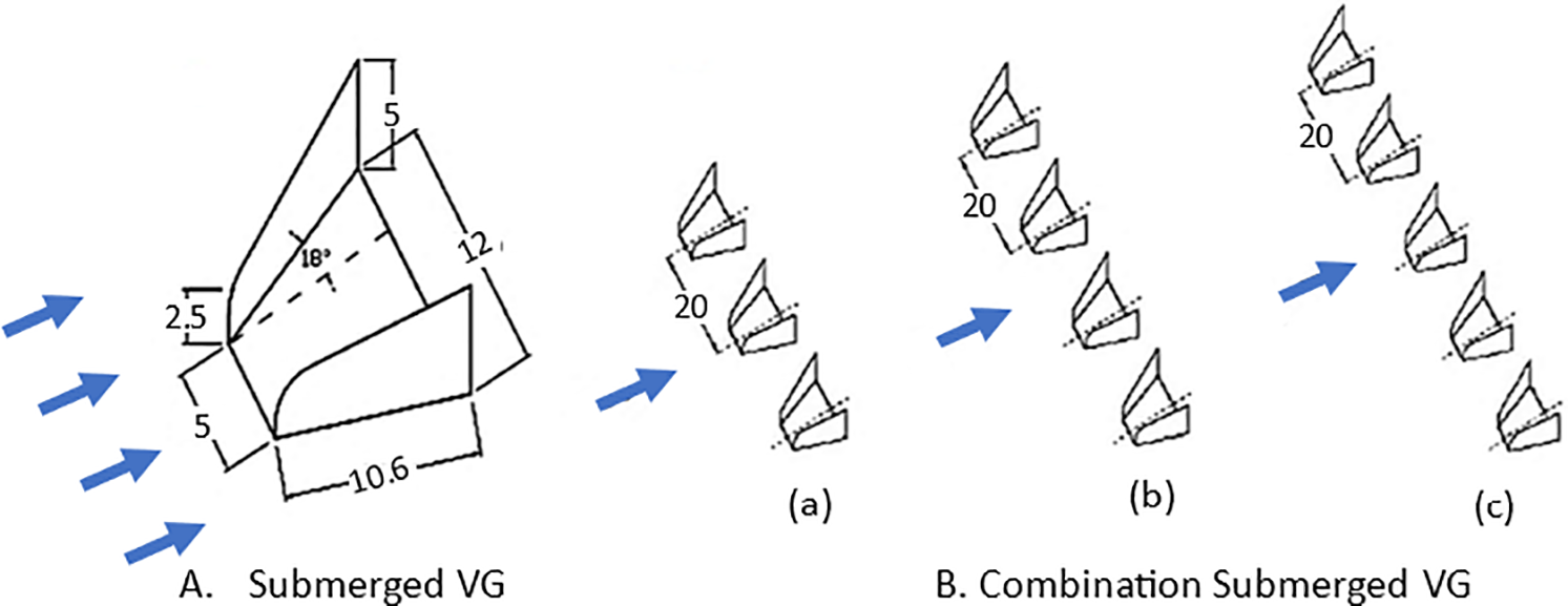
Figure 15: (A) Schematic of submerged vortex generator, (B) Combination of submerged vortex generators with a. 3 VGs, b. 4 VGs, and c. with 5 VGs. [4]. (all dimensions are in mm)
Tournier et al., 2006 [8] performed an experimental investigation of an S-shaped inlet duct in transonic flow for cruise missiles to control the flow separation during the missile manoeuvre. During maneuvers of the cruise missile, both the external conditions and interaction with the forebody could create severe losses in the flow of energy. The flow separation inside the inlet duct causes a flow distortion at the compressor face, leading to instabilities, especially in compact air inlets such as those used in missiles’ airbreathing inlets. The experiments are aimed at evaluating different control techniques in terms of distortion level, pressure recovery, and aerodynamic performance. A distortion device was then introduced at the entrance of the inlet to simulate thick boundary layer ingestion. VGs were then used in a first attempt to enhance the inlet performance.
According to Anderson et al. [54], the VGs can be divided into two main configurations. The first configuration is referred to as counter-rotating, and the second configuration is referred to as co-rotating, as shown in Fig. 16 [54]. The inclination of the VGs to the upstream flow represents the difference between these two configurations. In the first configuration, half of the VGs are inclined by a positive angle of attack, and the others by a negative angle of attack. Also, it creates vortices in the opposite direction. In the second configuration, all VGs are inclined at the same angle, and the created vortices rotate in the same direction. Within the S-shaped duct inlet, the Co-rotating configurations are more effective, especially in the boundary layer region. Counter-rotating configurations are effective in reducing flow separation. The counter-rotating configuration has disadvantages, including induced vortices that cause lift off the duct surface, higher total pressure loss, and greater total pressure distortion compared to the co-rotating configuration.
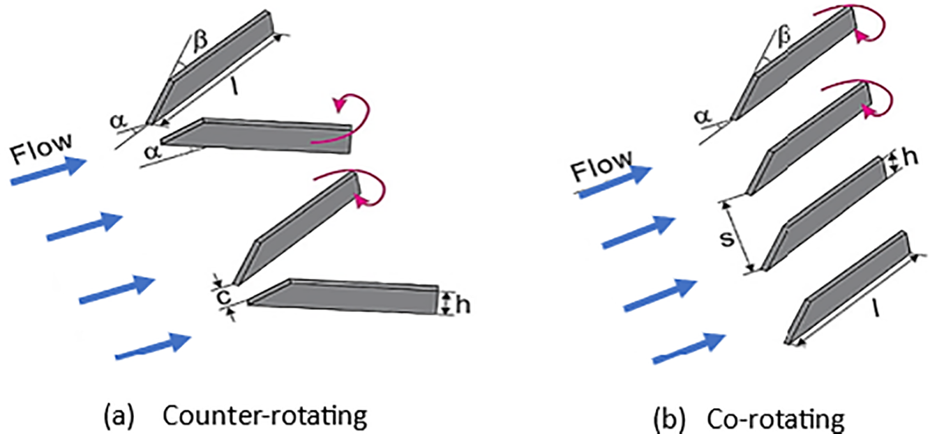
Figure 16: Vortex Generators. (a) Counter-Rotating, (b) Co-rotating [54]
Zhang et al. [55], Zhang et al. [56], and Zhang et al. [57] conducted a series of experimental and numerical investigations on the flow mechanisms in an S-shaped duct as a baseline case, without LPVGs flow control, and with two configurations of LPVGs. They reported that boundary layer separation and counter-rotating vortices in both the casing and hub regions dominated the flow structures within the baseline case. However, a strong adverse pressure gradient existed between the first bend and the second bend of the S-shaped duct on the casing, which caused the casing boundary layer to separate. Therefore, they used LPVGs on the casing, arranged in both counter-rotating (Fig. 16a) and co-rotating configurations (Fig. 16b). The addition of LPVGs results in the generation of another pair of counter-rotating vortices at the AITD second bend, which helps to delay or prevent boundary layer separation. The results from the two configurations show that a reduction in casing boundary layer separation leads to a consequential increase in the CPR and a reduction in overall pressure losses, CTL. Additionally, the co-rotating configuration 2 was found to be more effective, as presented in Fig. 17.
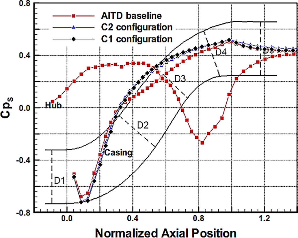
Figure 17: Static pressure coefficient (Cps = CPR) along the hub and casing with and without flow control [57]
Anabtawi et al. [16] investigated the effectiveness of vane-type VGs on flow distortion in a boundary layer ingesting an offset diffuser. They reported that the VGs should have a boundary layer thickness to affect the boundary layer and to induce a change in the diffuser secondary flow. They suggested that a combination of passive flow control with other methods could help reduce distortion due to the losses associated with such large generators. This coupling between passive flow control with inlets results in significant boundary layer ingestion. Vane-type VGs were typically used to mix and re-energize the boundary layer fluid with higher-momentum fluid from the free stream. They found that it is more difficult to manage secondary flows due to the large amounts of swirl, which is exacerbated by the scale of the necessary generators and their created vortices. Also, the scale suggests that large losses in CPR of the duct would be associated with viscous losses resulting from skin friction on the effectors.
Reichert and Wendt [58–60] performed numerous experiments on an S-shaped duct, which features a circular cross-sectional area to enhance performance. They assessed the effect of various configurations of low-profile VGs with a wishbone type [58] as shown in Fig. 18. Three parameters of VGs were varied to determine their effect on the performance: VG height (h), the streamwise location of the VG array, and VG spacing.
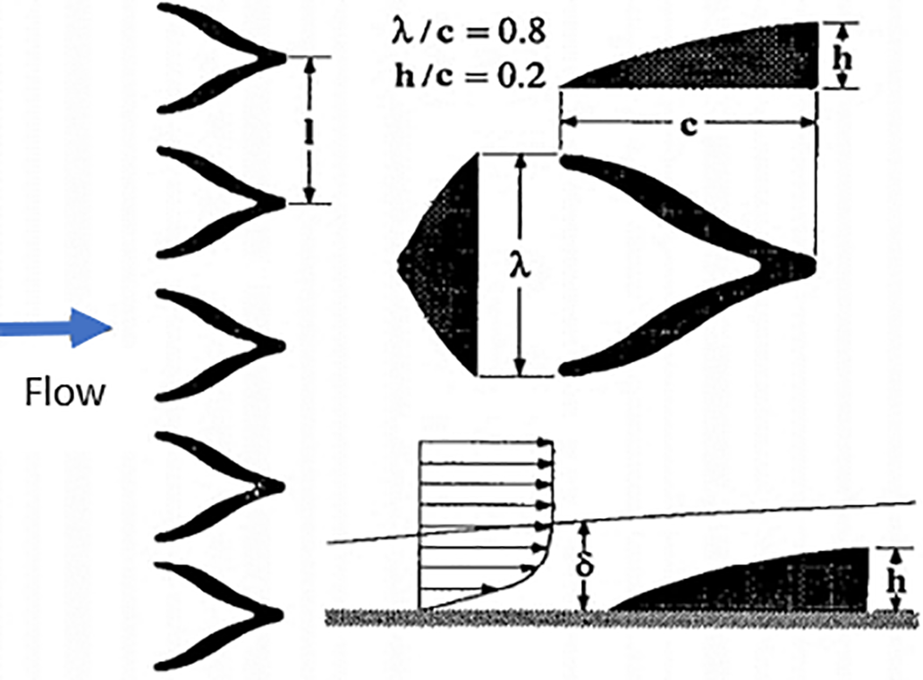
Figure 18: Wishbone Low-profile Vortex generator [58]
The results show that the largest vortex generators were the most effective in reducing DC(60°) but did not produce the greatest CPR. Additionally, no one from the test configuration of VGs was able to eliminate the flow separation. After this time, Reichert and Wendt [59] used the same S-shaped diffuser with seven configurations of Tapered Fin type VGs, as shown in Fig. 19. The best configuration yielded more than 50% reeducation in DC(60°) and a 0.5% improvement in CPR.
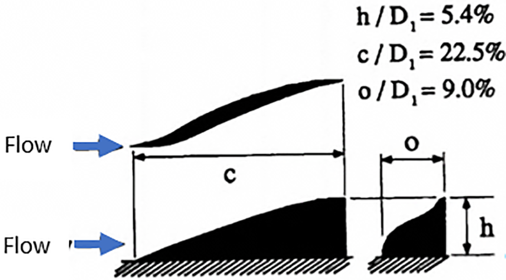
Figure 19: Tapered-fin type vortex generators [59]
In 1996, different configurations of both co-rotating and counter-rotating arrays of VGs were assessed in an S-shaped diffuser [60], as illustrated in Fig. 20. The information from the results shows that the best configuration can improve the CPR by 0.5% and reduce the DC(60°) by 50%.
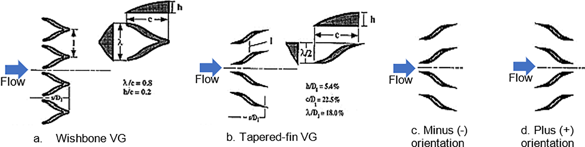
Figure 20: Vortex generator array geometry. (a) Wishbone VG, (b) Tapered-fin VG, (c) Minus orientation VG, and (d) Plus orientation VG [60]
Santner et al. [61] conducted an experimental investigation on a rectangular S-shaped diffuser with strong curvature. Additionally, they investigate the impact of low-profile VGs, which are applied within the first bend of the S-shaped diffuser to energize the boundary layer and further reduce or suppress the separation that occurs. The low-profile VGs were arranged in a counter-rotating scheme. Counter-rotating low-profile VGs were formed by stamping their shape into a band of copper foil and were glued to the first bend of the surface, as shown in Fig. 21.
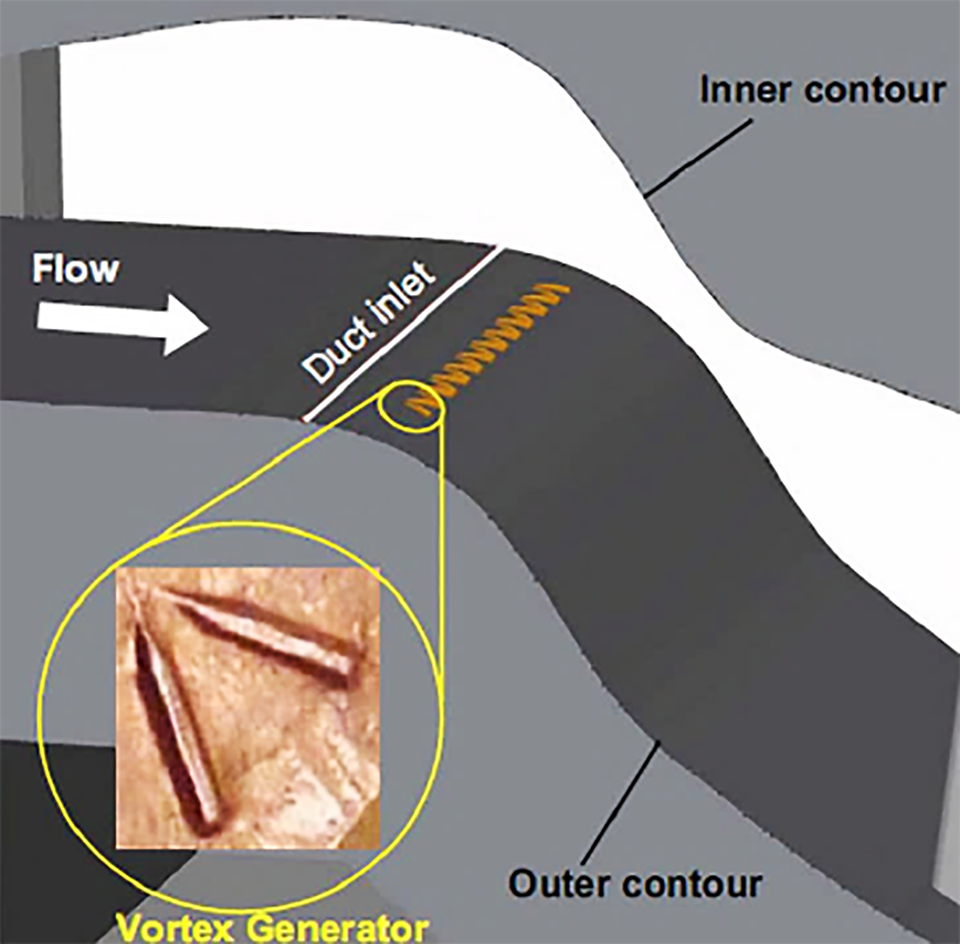
Figure 21: 2D-duct with the suggested position for VGs [61]
The investigation was conducted at Ma of 0.6. They concluded that adding VG could reduce separation and improve the CPR, as shown in Fig. 22, but has no significant influence on separation within the turbine duct due to the presence of wakes and strong secondary flow effects.
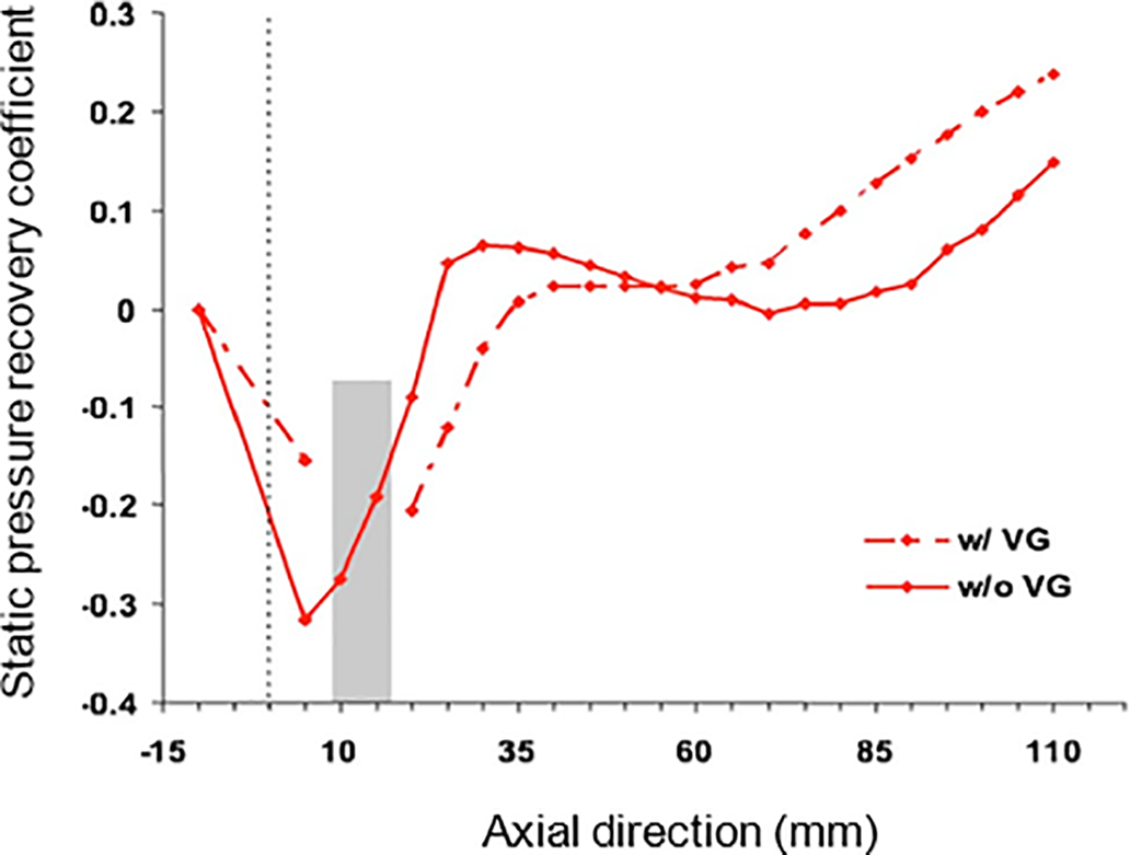
Figure 22: Distribution of the CPR along the outer surface of the 2D S-shaped duct [61]
Paul et al. [62] conducted experiments using a rectangular cross-section S-shaped diffuser. They investigated the effects of the corners on the exit flow pattern. The Fishtail VG type is evaluated at various numbers and locations within the rectangular S-duct diffuser to control secondary flow, as shown in Fig. 23. It was found that the locations of VGs were more effective than the number of VGs used. The best combination produced improvement in CPR and CTL of 48.57% and 3.54%, respectively. Additionally, the DC(60°) was reduced from 0.168 to 0.141.
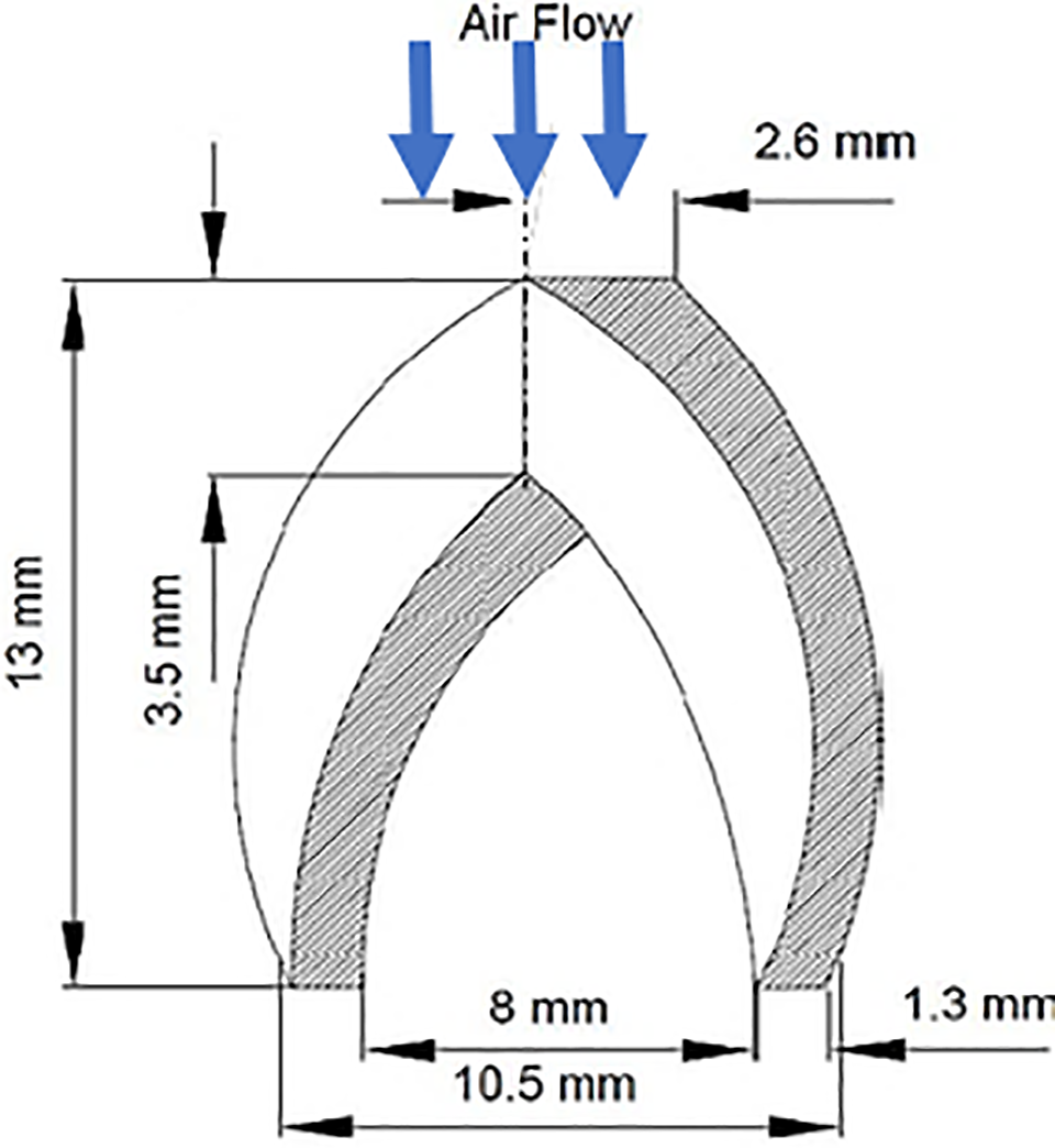
Figure 23: Fishtail shaped submerged vortex generator [62]
Vakili et al. [63] investigated different geometries of VGs to improve the performance of the S-duct diffuser, which has a circular cross-sectional area and an entrance with turbulent flow at a Mach number of 0.6. Half-wing type VG, with counter-rotating configuration, and circular rail type flow control devices in S-shaped diffuser used inside the S-duct diffuser for flow control. The flow was improved by eliminating flow separation in diffusing S-ducts. The performance enhancement achieved by employing a half-wing type VG was higher than that with rail-type flow control devices. Additionally, the level of secondary flow was reduced with the wing-type VGs, while it increased with the flow control rail.
Seddon [64] investigated the effect of wall fences with various sizes and combinations on reducing swirl in an S-duct that develops due to high angles of attack. The conclusion was that improvement of the total pressure led to a large reduction in swirl at high incidence with small-size fences and a small effect on CPR at low incidence. On the other hand, Sullerey and Mishra [65] investigated the influence of boundary layer fences in improving the performance of S-shaped diffusers of rectangular cross-section in a uniform inlet flow. They used different fence heights to achieve optimum performance of the duct, and a significant improvement in performance of the S-shaped diffuser has been observed. After this, Sullerey et al. [66] experimentally investigated the effect of various fences and VG configurations on reducing exit flow distortion and improving CPR in two-dimensional S-duct diffusers of different radius ratios. The results indicate that the performance improvement of the S-shaped diffuser can be achieved with judicious distribution of fences and VGs.
Lockheed Martin and NASA Glenn Research Center jointly presented results for designing and verifying an ultra-compact, highly survivable engine inlet subsonic S-shaped duct based on the emerging technology of Active Inlet Flow Control [67]. Two configurations of flow control were designed for investigation with the baseline duct. The first configuration used two arrays of 36 co-rotating micro vane VGs with different design factors, as in Fig. 24. The second configuration used two arrays of 36 micro air-jet (microjet) VGs. Design of Experiments (DOE) and CFD were used for optimization of the microvane array. Microvane VGs perform as well as microjet VGs, with a 5% increase in CPR and a 50% decrease in DC(60°).
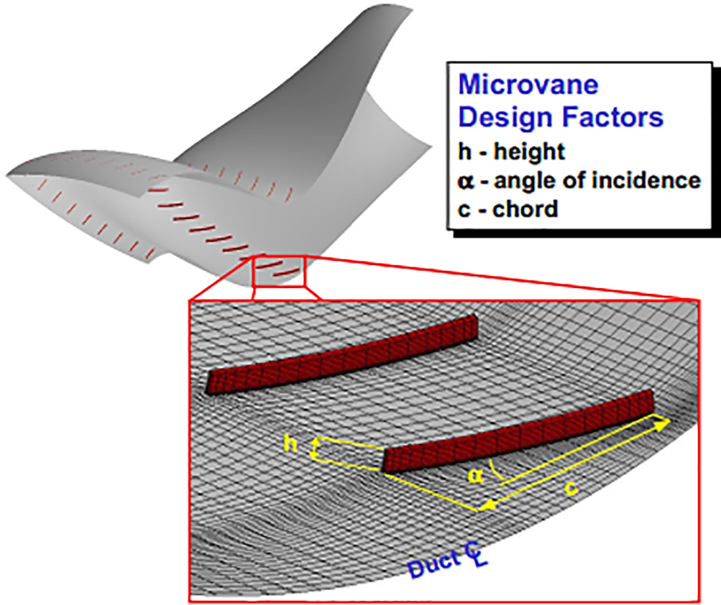
Figure 24: Co-rotating microvane VGs with different design factors [67]
Shu and Guo [68] conducted an experimental and numerical study on the highly curved serpentine inlet S-duct of an advanced Uninhabited Combat Air Vehicle (UCAV). A single array of ten rectangular-shaped VGs is employed within the inlet. The investigation examined the effects of VGs on the performance of a serpentine inlet instrumented at various mass flow ratios, free stream Mach numbers, angles of attack, and yaw angles. They concluded that the application of the VGs resulted in a decrease in the DC(60°) from 11.7% to 2.3%. Also, when the angle of attack rises from −4° to 8°, both the CPR and DC(60°) go down.
Recently, Tanguy et al. [69] and Tanguy et al. [70] investigated the ability of VGs to reduce the unsteady distortion at the exit plane of an S-duct AIP by using a Stereo Particle Image Velocimetry system PIV. The VGs were made of a 0.2 mm-thick aluminum sheet with arrays. Two arrays of VGs were fixed on the surface of the S-duct in a co-rotating configuration at each side of the duct symmetry plane. Different configurations of VGs were assessed. According to the results, the DC(60°) is substantially affected with a reduction of up to 50% compared to the datum configuration. However, the addition of VGs can both increase and reduce the DC(60°) relative to the datum case. Also, the CPR was improved in all the VG cases with a reduction of 30% in pressure loss.
Marn et al. [71] and Göttlich et al. [72] conducted a series of experimental and numerical investigations, in addition to flow visualization using LDV, on the aggressive S-shaped intermediate turbine duct. They study the effectiveness of blade tip gap on the flow of aggressive diffuser downstream transonic turbine stage with two parts: the first part with time average results [71], and the second part with time resolved results and surface flow [72]. Therefore, two different tip gap sizes were investigated, and this effect is different depending on the location of the measurement plane within the S-duct. They reported that it is also necessary to keep the blade tip clearance constant during operation, particularly if the ITD is operating near separation. Also, the results show that the flow within the S-shaped duct is extremely sensitive to relatively small changes at the duct inlet. Göttlich et al. [72] used another approach, which is called the integrated concept (IC), to shorten the S-duct and then the engine length. These approaches mean that the struts, mounted in the transition S-duct, replace the usually following low-profile vane row. The results show that the total pressure loss base design is 4.4% and the total pressure loss with IC is 4.3%, i.e., the pressure loss with IC is slightly smaller than with the base design. Nevertheless, the important benefit is that a significant weight reduction of the blading between 20% and 39% is possible.
Jessam et al. [23,73] conducted an experimental and numerical investigation on an aggressive S-shaped diffuser. In [23], they presented an experimental and numerical investigation on the effect of using different combinations of passive flow control, co-rotating streamline sheet at different installation planes, 3, 4, and 5, on the performance, as shown in Fig. 25. The use of flow modifiers results in a significantly decreased outer surface boundary layer separation, which consequential improves the static pressure coefficient and reduction of total pressure losses.
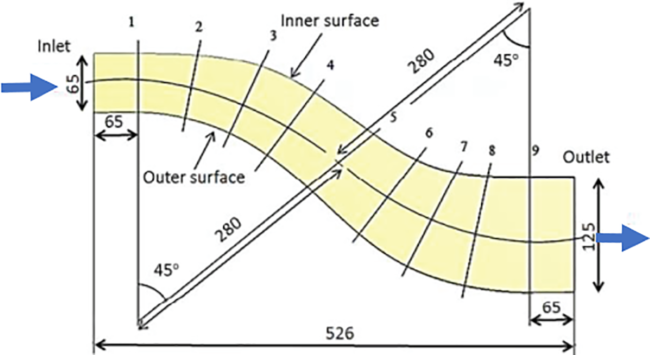
Figure 25: Geometry of the modeled S-shaped diffuser and plane of interest (all dimensions in mm) [73]
In [73], they investigated the effect of three types of flow modifiers, i.e., VGs, on the performance of the S-diffuser, which were fixed on the top and bottom surfaces at the optimum installation plane (5) as shown in Fig. 26. The three types were: type one, Co-rotating low-profile, type 2, Co-rotating stream lie sheet, and type three, Trapezoidal submerged.
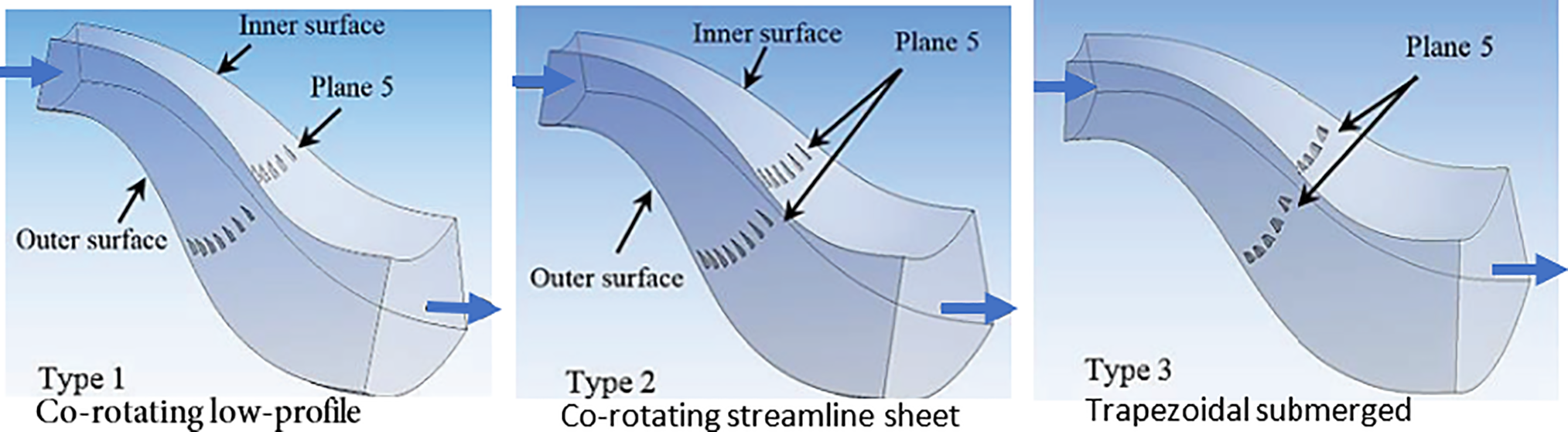
Figure 26: Distribution of three types of Flow Modifiers on the inner and outer surfaces of the S-shaped aggressive diffuser at the optimum plane, plane (5) [23]
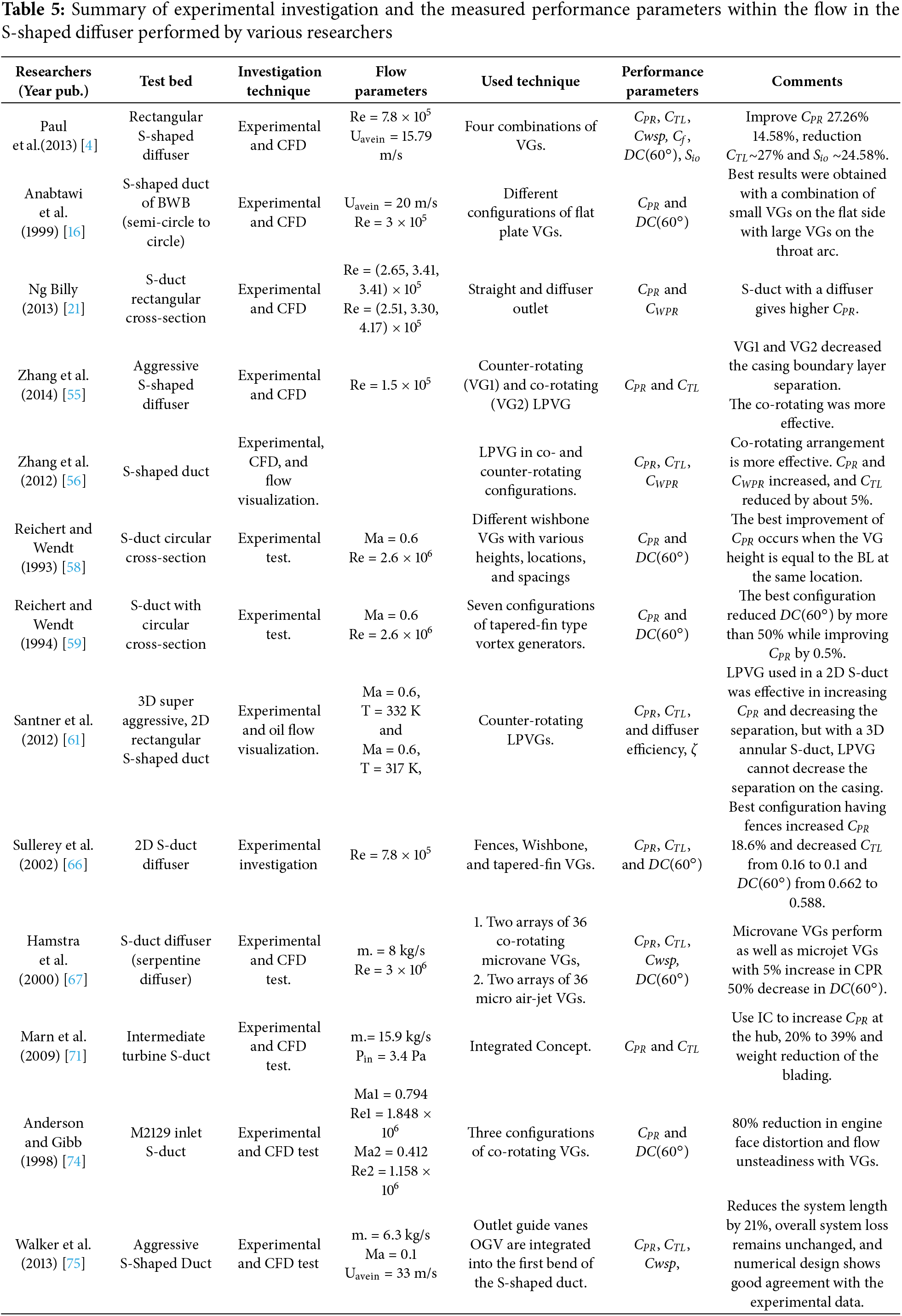
The investigation results show that type 2 gives maximum static pressure recovery of 0.77 and a minimum distortion coefficient of 0.086. Table 5 summarizes an experimental investigation within the flow of an S-shaped diffuser with different geometries, boundary conditions, and different combinations of VGs.
5.3 Hybrid Flow Control (Passive and Active Combinations)
Combining the passive and active methods might achieve the hybrid flow control methods in S-shaped diffusers. Compared to active or passive flow control, the hybrid flow control improves the S-shaped diffuser performance indicators like total pressure recovery and flow distortion more than employing a single method alone. It pulls up the strengths of the active or the passive methods when used individually and manages the possible limitations. For example, active methods consume energy to control the flow, while the hybrid system, by adding passive approaches, like VG, reserves the energy required by the active approach is specific aeroengine operational conditions. This combination of hybrid flow control balances the fuel consumption and the engine performance via the S-shaped diffuser improves the balance.
On the other hand, the aeroengine operates at various speeds and various flight pull-up and diving conditions, which cause unstable and abnormal flow structure inside the S-shaped diffuser. These multiple operational conditions could not be managed successfully by passive methods, as they are effective only at fixed design conditions. When the aeroengine runs at off-design conditions, the passive methods strive to control the flow. Hybridization of the active techniques with the active ones secures control of aggressive flow and upholds high performance over a wide range of flight speeds and sharp maneuverability of the aircraft.
An experimental and numerical study was conducted with passive and active flow control devices by Owens et al. [19]. They investigated the S-inlet diffuser with significant BLI (35%) experimentally and numerically with passive and active flow controllers. Different jet mass flow rates and jet distribution patterns were used in the inlet to control distortion; also, the vane configuration was evaluated. A combination or hybrid vane/jet configuration was assessed to take advantage of the strengths of both types of devices. Measurements of distortion and pressure recovery were made at the AIP. The VG design placed groups of six vanes in four different regions toward the front of the diffuser, the same as in Fig. 27, and the combinations of control jet orifice as in Fig. 27.
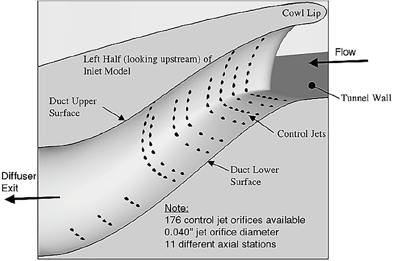
Figure 27: A view of the left half of the inlet diffuser illustrates all available jet locations and the general location of the vortex generators in the experimental wind tunnel [27]
After analyzing the experimental and numerical results, the conclusions show that the circumferential distortion was reduced to acceptable levels with control jets and vanes, but the point-design vane configuration produced higher distortion levels at off-design settings. At the same time, the combination of vane and jet flow control configuration (hybrid) reduced the off-design distortion levels to acceptable ones and used less than 0.5% of the inlet mass flow to supply the jets.
Gorton et al. [76] conducted experiments by Boundary layer ingestion BLI with active and passive flow control to improve overall system performance for a Blended Wing Body configuration BWB. The model inlet design was evaluated in the NASA Langley Basic Aerodynamics Research Tunnel, Fig. 28. The active flow control was provided by high mass flow pulsing actuators flow control. Measurements of the mass flow through the duct and the actuators, as well as the duct surface static pressures, were made at the onset boundary layer.
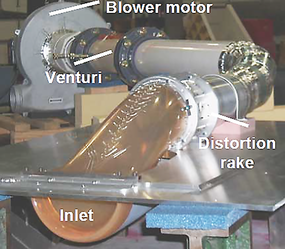
Figure 28: Features of the experimental inlet model [76]
The passive device for flow control, micro vortex generators (MVGs), were installed inside the inlet approximately 13% of the onset boundary layer height and were arranged in a co-rotating pattern. They observe from the results that the DC(60°) value at Ma = 0.15 was reduced from 29% for the baseline to 4.6% for the active flow control case. The maximum effectiveness of the active flow control pulsed jets is at 0.55% of the actuator mass flow rate of the inlet mass flow.
Furthermore, Gissen et al. [77] performed an experimental investigation using 5% scale model of a blended-wing-body offset diffuser at various subsonic speeds up to 0.55 Mach number to assess the effect of a hybrid flow control method comprised of vanes and synthetic jets. They found that the hybrid imposed a significant reduction in the flow distortion, which is higher than the case of active or passive methods. The hybrid flow control using vanes, as passive, and synthetic jets, as active, reduced the distortion by 35% at an operational speed of 0.55 Mach number.
It is worth mentioning about S-shaped experiment performed with water as the working fluid. Sakr et al. [78] performed an experimental investigation on twelve models of rectangular S-shaped diffusers. They investigated the diffuser performance at different parameters, including area ratios, curvature ratios, inflow Reynolds numbers, turning angles of 45/45, 60/60, and 90/90 degrees, and flow paths of 45/45, 60/30, and 30/60. The designed, fabricated, and utilized experimental setup is shown in Fig. 29. They concluded that the diffuser energy loss coefficient is strongly affected by the geometrical parameters of the S-shaped diffuser and the inflow Reynolds number. Increasing area ratio, curvature ratio, and inflow Reynolds number increase the diffuser performance. The turning angle plays an important role in improving the S-shaped diffuser performance. But the diffuser performance decreases when the turning angle is larger than 60° and the flow path changes further than the symmetric path (45°/45°)
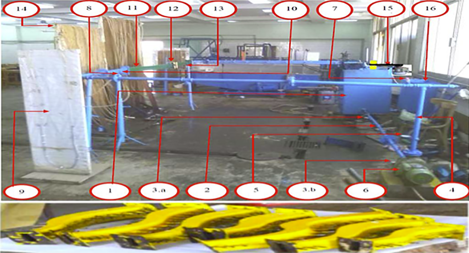
Figure 29: Experimental setup of S-shaped diffuser with water flow. 1. Main tank, 2. Suction pipe, 3. Suction pressure gauges, 4. Delivery pipe, 5. Delivery pressure gauge, 6. Centrifugal pump, 7. Control valve, 8. Orifice-meter, 9. U-tube manometer, 10. Converter, 11. Upstream tangent duct, 12. S-diffuser model, 13. Downstream duct, 14. Multi-tube manometer, 15. Mixer electric motor, 16. Calibration tank [78]
6 Data-Driven Research Directions on Enhanced S-Shaped Diffusers
After an insight into the literature and analyzing the existing research trend, it has been realized that the last decade has experienced a direction towards computational methods to improve the S-shaped diffusers’ performance and investigate and optimize their design by validated CFD simulation and analysis. However, it is believed that merging the computational methods with data-driven approaches may effectively improve the research quality and accuracy.
Data-driven trends for design optimization and performance enhancement of S-shaped diffusers are shifting from traditional parametric studies toward advanced artificial intelligent and automated optimization approaches. This direction allows designers to efficiently explore complex geometries to maximize pressure recovery, minimize total pressure loss, and reduce flow distortion.
Lefantzi and Knight [79] developed and validated an automated design optimization for a subsonic S-shaped diffuser. The optimization was based on the minimization of the total pressure and the flow distortion at the exit, while maintaining the total pressure recovery. To synthesize the automated analysis and optimization method, they created a subsonic diffuser design system, which utilizes four commercial software tools. These tools are a three-dimensional solid modeler for the generation of diffuser geometries, Pro/Engineer, an elliptic mesh generator, GridPro, an aerodynamic simulation package, GASPex, and a gradient-based optimizer to traverse the design space automatically, CFSQP.
Chiereghin et al. [80] and Tridello [81] employed a free-form deformation method coupled with a multi-objective genetic algorithm to improve aerodynamic characteristics in a circular cross-section S-shaped diffuser. They intended to reduce the flow distortion and pressure losses through optimization of the intake shape by means of CFD. Chiereghin et al. [80] employed the Non-dominated Sorted Genetic Algorithm and achieved a total pressure losses reduction of 20% and a maximum swirl reduction of 10%. On the other hand, Tridello [81] employed the Genetic Diversity Evolutionary Algorithm. The results show a maximum total pressure loss reduction of 24% and a maximum swirl reduction of 19%.
Fazli and Mahmoodi [82] optimized an asymmetric S-shaped diffuser aiming at a reduction in the total pressure loss and flow distortion at the exit plane. They used a GA and an artificial neural network (ANN) in the optimization process, which included computational modeling, mesh generation, 3D simulations, database preparation, and ANN training. A comparison of the optimized results with the baseline geometry of the S-shaped diffuser shows a flow distortion reduction of 74% and a total pressure loss reduction by around 16%.
The use data data-driven approaches in the design and performance improvement of S-shaped diffusers is widely discussed and utilized by Stahl and his working teams, e.g., Stahl and Benton [83], and Stahl et al. [84]. They concluded that the advantages of data-driven analysis could be applied to any flow field for which time-resolved snapshots are available, regardless of geometry and flow parameters, including the S-shaped diffusers, without the need to solve the linearized Navier-Stokes equations.
This paper reviews and highlights a wide range of experimental research efforts on the performance improvements of the aeroengine by mitigating the setbacks in the air intake S-shaped diffusers. The following could be the key findings from this review.
- The study of flow characteristics within an S-shaped diffuser has been of fundamental interest to researchers in fluid mechanics and aerodynamics because of its important applications in aeroengines.
- The flow inside the S-shaped diffuser is more complicated than a normal straight diffuser due to the inflexion in the curvature along the direction, causing flow reversed and boundary layer separation, which affects the pressure recovery, pressure loss, and flow uniformity.
- The design parameters, including area ratio, aspect ratio, shape of cross-sectional area, turning angle, and turning radius, have a significant effect on the flow structure and, consequently, the performance of the S-shaped diffuser.
- Many researchers have studied enhanced S-shaped diffusers through the implementation of various techniques like passive flow control, active flow control, and hybrid flow control to improve the performance by increasing the static pressure recovery and reducing total pressure loss and distortion.
- The tested active flow control, depending on blowing or suction air, is achieved by adding auxiliary power into the flow.
- The passive flow control is mainly achieved by the installation of VGs, which are either micro-ramps or micro-vanes. The VGs could be co-rotating and counter-rotating.
- The passive flow control techniques are easy to implement and free from any type of external energy requirements.
- Hybrid methods that combine active and passive have a higher influence on the flow control and the diffuser enhancement compared to active or passive alone.
- The new trend in the S-shaped diffuser performance improvement and design optimization by integrated CFD methods and data-driven AI, like GA, NNA, and machine learning, is recommended as a futuristic research trend.
Acknowledgement: The Authors acknowledge University Teknologi PETRONAS for the logistical support to produce this literature paper as part of the PhD work of the fourth author, Raed, by using the facilities in the Advanced Fluid Dynamics Lab, Mechanical Engineering Department. Raed expresses his thankful remarks to Universiti Teknologi PETRONAS for supporting his PhD study under the graduate assistance (GA) financial scheme.
Funding Statement: The authors received no specific funding for this study.
Author Contributions: The authors confirm contribution to the paper as follows: Conceptualization, Hussain H. Al-Kayiem and Raed A. Jessam; methodology, Hussain H. Al-Kayiem and Raed A. Jessam; data curation, Hussain H. Al-Kayiem, Raed A. Jessam, Safaa M. Ali, and Sundus S. Al-Azawiey; writing—original draft preparation, Raed A. Jessam; writing—review and editing, Hussain H. Al-Kayiem, Safaa M. Ali, and Sundus S. Al-Azawiey; supervision, Hussain H. Al-Kayiem; project administration, Raed A. Jessam. All authors reviewed the results and approved the final version of the manuscript.
Availability of Data and Materials: Not applicable as the article is a reviewed and comparative in nature.
Ethics Approval: Not applicable.
Conflicts of Interest: The authors declare no conflicts of interest to report regarding the present study.
Glossary
| Symbols | |
| CPR | Static pressure recovery coefficient |
| CTL | Total pressure loss coefficient |
| DC(45°) | Distortion coefficient with 45° |
| DC(60°) | Distortion coefficient with 60° |
| Dh | Hydraulic diameter (m, mm) |
| h | Height of energy promoter (mm) |
| k | Turbulent kinetic energy (m2/s2) |
| l | Length of energy promoter (mm) |
| Ld | Length of the diffuser (m, mm) |
| lin | Inlet conduit length (mm) |
| lout | Outlet conduit length (mm) |
| p | Pressure (N/m2) |
| R | S-shaped diffuser centerline turning radius (mm) |
| TI | Turbulence intensity (%) |
| Uav. in | Average inlet velocity (m/s) |
| Uav. out | Average outlet velocity (m/s) |
| Abbreviations | |
| AD/EP | S-Shaped Aggressive Diffuser with Energy Promoter |
| AIP | Aerodynamic Inlet Plane |
| ANN | Artificial Neural Network |
| Bare D | Bare S-Shaped Diffuser |
| GA | Genetic Algorithm |
| Bare AD | Bare S-Shaped Aggressive Diffuser |
| LPVG | Low Profile Vortex Generator |
| Ma | Mach number |
| RANS | Reynolds Averaged Navier-Stokes |
| Re | Reynolds number |
| Subscripts | |
| d | Dynamic |
| in | Inlet |
| out | Outlet |
| s | Static |
| t | Total |
| w | Wall |
| Greek letters | |
| θb | S-shaped diffuser turning angle (deg) |
| ρ | Density of air (kg/m3) |
| ε | Turbulence kinetic energy dissipation rate (m2/s3) |
| μ | Viscosity of air (kg/m.s) |
| τw | Wall shear stress (kg/m.s2) |
References
1. Al-Kayiem HH, Salih TW, Govindasamy D. Coupled analytical-numerical procedure to solve the double wedge spiked supersonic intake flow field. Appl Mech Mater. 2012;225:67. doi:10.4028/www.scientific.net/AMM.225.67. [Google Scholar] [CrossRef]
2. El-Sayed AF, Emeara MS. Aero-engines intake: a review and case study. J Robot Mech Eng Res. 2016;1(3):35–42. doi:10.24218/jrmer.2016.15. [Google Scholar] [CrossRef]
3. Wróblewski M, Adamczyk M, Kozakiewicz A. Areas of investigation into air intake systems for the impact on compressor performance stability in aircraft turbine engines. Adv Sci Technol Res J. 2022;16(1):62–74. doi:10.12913/22998624/143290. [Google Scholar] [CrossRef]
4. Paul AR, Ranjan P, Patel VK, Jain A. Comparative studies on flow control in rectangular S-duct diffuser using submerged-vortex generators. Aerosp Sci Technol. 2013;28:332–43. doi:10.1016/j.ast.2012.11.014. Gupta A, Singh H. Experimental and computational study of performance characteristics in S-shaped diffuser. In: Proceedings of the Canadian Society for Mechanical Engineering International Congress (CSME) Congress 2022; 2022 Jun 5–8; Edmonton, AB, Canada. doi:10.7939/r3-wbh7-ze35. [Google Scholar] [CrossRef]
5. Madadi A, Kermani MJ, Nili-Ahmadabadi M. Aerodynamic design of S-shaped diffusers using ball-spine inverse design method. J Eng Gas Turbine Power. 2014;136(12):122606. doi:10.1115/1.4027905. [Google Scholar] [CrossRef]
6. Al-Kayiem HH, Jessam RA, Hamdi SS, Ali M, Tukkee AM. Numerical evaluation of the performance enhancement of S-shaped diffuser at the intake of gas turbine by energy promoters. Energy Eng. 2025;122(4):1311–35. doi:10.32604/ee.2025.061709. [Google Scholar] [CrossRef]
7. Vaccaro JC, Elimelech Y, Chen Y, Sahni O, Jansen KE, Amitay M. Experimental and numerical investigation on steady blowing flow control within a compact inlet duct. Int J Heat Fluid Flow. 2015;54(4):143–52. doi:10.1016/j.ijheatfluidflow.2015.05.011. [Google Scholar] [CrossRef]
8. Tournier SE, Paduano JD, Pagan D. Flow control in a transonic inlet. In: Proceedings of the 36th AIAA Fluid Dynamics Conference and Exhibit; 2006 Jun 5–8; San Francisco, CA, USA. p. 5–8. doi:10.2514/6.2006-3883. [Google Scholar] [CrossRef]
9. Vaccaro JC, Yossef E, Amitay M. Experimental investigation of actuators for flow control in inlet ducts. In: Proceedings of the 63rd Annual Meeting of the APS Division of Fluid Dynamics; 2010 Nov 21–23; Long Beach, CA, USA. doi:10.2514/6.2010-862. [Google Scholar] [CrossRef]
10. Kumar V, Alvi FS. Use of high-speed microjets for active separation control in diffusers. AIAA J. 2006;44(2):273. doi:10.2514/1.8552. [Google Scholar] [CrossRef]
11. Reynolds T, Reeder M. Variation of flow control configurations to improve submerged inlet uniformity. In: Proceedings of the 47th AIAA Aerospace Sciences Meeting. AIAA Aerospace Sciences Meeting Including the New Horizons Forum and Aerospace Exposition; 2009 Jan 5–8; Orlando, FL, USA. doi:10.2514/6.2009-1259. [Google Scholar] [CrossRef]
12. Shanan YH. Active flow control of a diffusing S-duct. Int J En Sci Technol. 2020;12(2):1–10. doi:10.4314/ijest.v12i2.1. [Google Scholar] [CrossRef]
13. Scribben AR, Ng W, Burdisso R. Effectiveness of a serpentine inlet duct flow control technique at design and off-design simulated flight conditions. J Turbomach. 2006;128(2):332–9. doi:10.1115/1.2098787. [Google Scholar] [CrossRef]
14. Amitay M, Pitt D, Glezer A. Separation control in duct flows. J Airc. 2002;39(4):616–20. doi:10.2514/2.2973. [Google Scholar] [CrossRef]
15. Vakili A, Wu J, Bhat M, Liver P. Compressible flow in a diffusing S-duct with flow separation. In: Heat transfer and fluid flow in rotating machinery. Washington, DC, USA: NASA; 1987. p. 201–11. [Google Scholar]
16. Anabtawi A, Blackwelder R, Lissaman P, Liebeck R. An experimental study of vortex generators in boundary layer ingesting diffusers with a centerline offset. In: 35th Joint Propulsion Conference and Exhibit; 1999 Jun 20–24; Los Angeles, CA, USA; p. 2110. doi:10.2514/6.1999-2110. [Google Scholar] [CrossRef]
17. Anderson BH, Miller DN, Addington GA, Agrell J. Optimal Micro-Jet flow control for compact air vehicle inlets. NASA/TM-2004-0212936. 2004 [cited 2025 Jan 1]. Available from: http://gltrs.grc.nasa.gov/. [Google Scholar]
18. Lee BJ, Liou MS. Re-design of boundary-layer-ingesting offset inlet via passive flow control. In: Proceedings of the 48th AIAA Aerospace Sciences Meeting Including the New Horizons Forum and Aerospace Exposition; 2010 Jan 4–7; Orlando, FL, USA. doi:10.2514/6.2010-842. [Google Scholar] [CrossRef]
19. Owens LR, Allan BG, Gorton SA. Boundary-layer-ingesting inlet flow control. J Aircr. 2008;45(4):1431–40. doi:10.2514/1.36989. [Google Scholar] [CrossRef]
20. Miller DS. Internal flow systems. Birmingham, UK: BHRA Fluid Engineering; 1978. [Google Scholar]
21. Ng BCN. Experimental and CFD study of effusion cooling in an S-bend diffusing passage [dissertation]. Kingston, ON, Canada: Queen’s University; 2014. [Google Scholar]
22. Asghar A, Stowe RA, Allan WD, Alexander D. Entrance aspect ratio effect on S-duct inlet performance at high-subsonic flow. J Eng Gas Turbine Power. 2017;139(5):52602. doi:10.1115/1.4035206. [Google Scholar] [CrossRef]
23. Jessam RA, Al-Kayiem HH, Nasif MS. Experimental and numerical analysis of different flow modifiers on the reversal flow region in S-shaped aggressive diffuser. AIP Conf Proc. 2018;2035(1):70008. doi:10.1063/1.5075598. [Google Scholar] [CrossRef]
24. Anand R, Rai L, Singh S. Effect of the turning angle on the flow and performance characteristics of long S-shaped circular diffusers. Proc Inst Mech Eng Part G J Aerosp Eng. 2003;217(1):29–41. doi:10.1243/095441003763031815. [Google Scholar] [CrossRef]
25. Wellborn SR, Reichert BA, Okiishi TH. An experimental investigation of the flow in a diffusing S-duct. In: 28th joint propulsion conference and exhibit; 1992 Jul 6–8; Nashville, TN, USA. p. 3622. doi:10.2514/6.1992-3622. [Google Scholar] [CrossRef]
26. Lee BJ, Kim C. Automated design methodology of turbulent internal flow using discrete adjoint formulation. Aerosp Sci. 2007;11:163–73. doi:10.1016/j.ast.2006.12.001. [Google Scholar] [CrossRef]
27. Ng Y, Luo S, Lim T, Ho Q. Three techniques to control flow separation in an S-shaped duct. AIAA J. 2011;49(9):1825–32. doi:10.2514/1.J050135. [Google Scholar] [CrossRef]
28. Thenambika V, Ponsankar S, Prabhu M. Design and flow analysis of S-duct diffuser with submerged vortex generators. Int J Eng Res Appl. 2016;6:79–84. [Google Scholar]
29. Koch S, Rütten M, Rein M. Experimental and numerical investigations on integrated intakes for agile and highly swept aircraft configurations. Vol. DGLR Paper-0173. Rostock, Germany: Deutsche Gesellschaft für Luft-und Raumfahrt-Lilienthal-Oberth eV; 2015. [Google Scholar]
30. Hylton MR. Assessment of an innovative experimental facility for testing diffusing serpentine inlets with large amounts of boundary layer ingestion [dissertation]. Blacksburg, VA, USA: Virginia Polytechnic Institute and State University; 2008 [cited 2025 Jan 1]. Available from: http://hdl.handle.net/10919/33969. [Google Scholar]
31. Ibrahim I, Ng E, Wong K, Gunasekaran R. Effects of centerline curvature and cross-sectional shape transitioning in the subsonic diffuser of the F-5 fighter jet. J Mech Sci Technol. 2008;22(10):1993–7. doi:10.1007/s12206-008-0744-7. [Google Scholar] [CrossRef]
32. Jiang F, Kontis K, White C. Experimental analysis of flow characteristics in S-shaped ducts at low speeds. Phys Fluids. 2024;36(10):107110. doi:10.1063/5.0228159. [Google Scholar] [CrossRef]
33. McElwain BD. Unsteady separation point injection for pressure recovery improvement in high subsonic diffusers [dissertation]. Cambridge, MA, USA: Massachusetts Institute of Technology (USA); 2002 [cited 2025 Jan 1]. Available from: https://apps.dtic.mil/sti/citations/tr/ADA405746. [Google Scholar]
34. Luers AS. Flow control techniques in a serpentine inlet: an enabling technology to increase the military viability of unmanned air vehicles [master’s thesis]. Cambridge, MA, USA: Massachusetts Institute of Technology; 2003 [cited 2025 Jan 1]. Available from: http://hdl.handle.net/1721.1/82780. [Google Scholar]
35. Debiasi M, Herberg MR, Yan Z, Dhanabalan SS, Tsai HM, Dhanabalan S. Control of flow separation in S-ducts via flow injection and suction. In: Proceedings of the 46th AIAA Aerospace Sciences Meeting and Exhibit; 2008 Jan 7–10; Reno, Nevada. AIAA 2008-74. doi:10.2514/6.2008-74. [Google Scholar] [CrossRef]
36. Zhang J, Yuan H, Wang Y, Huang G. Experiment and numerical investigation of flow control on a supersonic inlet diffuser. Aerosp Sci Technol. 2020;106(4):106182. doi:10.1016/j.ast.2020.106182. [Google Scholar] [CrossRef]
37. Khan ZU, Johnston JP. On vortex generating jets. Int J Heat Fluid Flow. 2000;21(5):506–11. doi:10.1016/S0142-727X(00)00038-2. [Google Scholar] [CrossRef]
38. Johnston JP. Pitched and skewed vortex generator jets for control of turbulent boundary layer separation: a review. In: Proceedings of the 3rd ASME/JSME Joint Fluids Engineering Conference; 1999 Jul 18–23; San Francisco, CA, USA. [Google Scholar]
39. Sullerey R, Pradeep A. Secondary flows and separation in S-duct diffusers-their detection and control. In: Proceedings of the 4th ASME/JSME Joint Fluids Engineering Conference; 2003 Jul 6–10; Honolulu, HI, USA. FEDSM2003-45109. doi:10.1115/FEDSM2003-45109. [Google Scholar] [CrossRef]
40. Sullerey R, Pradeep A. Secondary flow control using vortex generator jets. J Fluids Eng. 2004;126(4):650–7. doi:10.1115/1.1779661. [Google Scholar] [CrossRef]
41. Pradeep A, Sullerey R. Active flow control in circular and transitioning S-duct diffusers. J Fluids Eng. 2006;128(6):1192–203. doi:10.1115/1.2353263. [Google Scholar] [CrossRef]
42. Sullerey R, Mangat V, Padhi A. Flow control in serpentine inlet using vortex generator jets. In: Proceedings of the 3rd AIAA Flow Control Conference; 2006 Jun 5–8; San Francisco, CA, USA. p. 3499. doi:10.2514/6.2006-3499. [Google Scholar] [CrossRef]
43. Mohseni K, Mittal R. Synthetic jets: fundamentals and applications. Boca Raton, FL, USA: CRC Press; 2014. [Google Scholar]
44. Agrawal A, Verma G. Similarity analysis of planar and axisymmetric turbulent synthetic jets. Int J Heat Mass Transf. 2008;51:6194–8. doi:10.1016/j.ijheatmasstransfer.2008.04.011. [Google Scholar] [CrossRef]
45. Kotapati RB, Mittal R, Cattafesta LN. Numerical study of a transitional synthetic jet in quiescent external flow. J Fluid Mech. 2007;581:287–321. doi:10.1017/S0022112007005642. [Google Scholar] [CrossRef]
46. Mossi K, Bryant R. Piezoelectric actuators for synthetic jet applications. MRS Online Proc Libr. 2003;785:118. doi:10.1557/PROC-785-D11.8. [Google Scholar] [CrossRef]
47. Jenkins LN, Gorton SA, Anders SG. Flow control device evaluation for an internal flow with an adverse pressure gradient. In: Proceedings of the 40th AIAA Aerospace Sciences Meeting & Exhibit; 2002 Jan 14–17; Reno, NV, USA. doi:10.2514/6.2002-266. [Google Scholar] [CrossRef]
48. Smith D, Amitay M, Kibens V, Parekh D, Glezer A. Modification of lifting body aerodynamics using synthetic jet actuators. In: Proceedings of the 36th AIAA Aerospace Sciences Meeting and Exhibit; 1998 Jan 12–15; Reno, NV, USA. doi:10.2514/6.1998-209. [Google Scholar] [CrossRef]
49. Amitay M, Smith BL, Glezer A. Aerodynamic flow control using synthetic jet technology. In: Proceedings of the 36th AIAA Aerospace Sciences Meeting and Exhibit; 1998 Jan 12–15; Reno, NV, USA. doi:10.2514/6.1998-208. [Google Scholar] [CrossRef]
50. Amitay M, Kibens V, Parekh D, Glezer A. The dynamics of flow reattachment over a thick airfoil controlled by synthetic jet actuators. In: Proceedings of the 37th Aerospace Sciences Meeting and Exhibit; 1999 Jan 11–14; Reno, NV, USA. p. 1001. doi:10.2514/6.1999-1001. [Google Scholar] [CrossRef]
51. Amitay M, Smith DR, Kibens V, Parekh DE, Glezer A. Aerodynamic flow control over an unconventional airfoil using synthetic jet actuators. AIAA J. 2001;39(3):361–70. doi:10.2514/2.1323. [Google Scholar] [CrossRef]
52. Mathis R, Duke D, Kitsios V, Soria J. Flow control in S-shaped air intake using zero-net-mass-flow. In: Proceedings of the 16th Australasian Fluid Mechanics Conference (AFMC); 2007 Dec 3–7; Gold Coast, Australia. p. 892–8. [Google Scholar]
53. Nasuhbeyoğlu B. Vortex generator design for high subsonic inlets [dissertation]. Ankara, Turkey: Middle East Technical University; 2014 [cited 2025 Jan 1]. Available from: http://etd.lib.metu.edu.tr/upload/12617958/index.pdf. [Google Scholar]
54. Anderson BH, Huang PS, Paschal EA, Cavatorta E. Study on vortex flow control of inlet distortion. J Propuls Power. 1992;8(6):1266–72. doi:10.2514/3.11472. [Google Scholar] [CrossRef]
55. Zhang Y, Hu S, Zhang XF, Benner M, Mahallati A, Vlasic E. Flow control in an aggressive interturbine transition duct using low-profile vortex generators. J Eng Gas Turbine Power. 2014;136(11):112604. doi:10.1115/1.4027656. [Google Scholar] [CrossRef]
56. Zhang Y, Hu S, Zhang XF, Benner M, Vlasic E. Flow control in an aggressive inter-turbine duct using low profile vortex generators. In: ASME turbo expo 2012: turbine technical conference and exposition. New York, NY, USA: ASME Press; 2012. p. 1609–19. doi:10.1115/GT2012-69951. [Google Scholar] [CrossRef]
57. Zhang Y, Lu X, Lei Z, Han G, Zhu J, Hu S. Parametric studying of low-profile vortex generators flow control in an aggressive inter-turbine duct. Proc Inst Mech Eng A J Power Energy. 2015;229(8):849–61. doi:10.1177/0957650915600085. [Google Scholar] [CrossRef]
58. Reichert BA, Wendt BJ. An experimental investigation of S-duct flow control using arrays of low-profile vortex generators. In: Proceedings of the 31st AIAA Aerospace Sciences Meeting and Exhibit; 1993 Jan 11–14; Reno, NV, USA. doi:10.2514/6.1993-18. [Google Scholar] [CrossRef]
59. Reichert BA, Wendt B. Improving diffusing S-duct performance by secondary flow control. Cleveland, OH, USA: NASA Lewis Research Center; 1994. doi:10.2514/6.1994-365. [Google Scholar] [CrossRef]
60. Reichert B, Wendt B. Improving curved subsonic diffuser performance with vortex generators. AIAA J. 1996;34(1):65–72. doi:10.2514/3.13022. [Google Scholar] [CrossRef]
61. Santner C, GÃķttlich E, Marn A, Hubinka J, Paradiso B. The application of low-profile vortex generators in an intermediate turbine diffuser. J Turbomach. 2012;134(1):11023. doi:10.1115/1.4003718. [Google Scholar] [CrossRef]
62. Paul AR, Kuppa K, Yadav MS, Dutta U. Flow improvement in rectangular air intake by submerged vortex generators. J Appl Fluid Mech. 2011;4(1):77–86. doi:10.36884/jafm.4.02.11919. [Google Scholar] [CrossRef]
63. Vakili A, Wu J, Liver P. Flow control in a diffusing S-Duct. In: Proceedings of the Shear Flow Control Conference; 1985 Mar 12–14; Boulder, CO, USA. doi:10.2514/6.1985-524. [Google Scholar] [CrossRef]
64. Seddon J. Understanding and countering the swirl in S-ducts: tests on the sensitivity of swirl to fences. Aeronaut J. 1984;88(874):117–27. doi:10.1017/S0001924000020340. [Google Scholar] [CrossRef]
65. Sullerey R, Mishra S. Performance improvement in S-duct diffusers with boundary layer fences. In: Proceedings of the ASME Fluids Engineering Summer Meeting; 2000 Jun 11–15; Boston, MA, USA. FEDSM2000-11240. [Google Scholar]
66. Sullerey R, Mishra S, Pradeep A. Application of boundary layer fences and vortex generators in improving performance of S-duct diffusers. J Fluids Eng. 2002;124(1):136–42. doi:10.1115/1.1436096. [Google Scholar] [CrossRef]
67. Hamstra J, Miller D, Truax P, Anderson B, Wendt B. Active inlet flow control technology demonstration. Aeronaut J. 2000;104(1040):473–9. doi:10.1017/S0001924000091971. [Google Scholar] [CrossRef]
68. Shu S, Guo RW. Serpentine inlet performance enhancement using vortex generator based flow control. Chin J Aeronaut. 2006;19(1):10–7. doi:10.1016/S1000-9361(11)60261-6. [Google Scholar] [CrossRef]
69. Tanguy GP, Zachos P, MacManus DG, Gil-Prieto D, Garnier E. Passive flow control study in a convoluted intake using Stereo Particle Image Velocimetry. In: Proceedings of the 34th AIAA Applied Aerodynamics Conference; 2016 June 13–17; Washington, DC, USA. p. 3563. doi:10.2514/6.2016-3563. [Google Scholar] [CrossRef]
70. Tanguy G, MacManus DG, Zachos P, Gil-Prieto PD, Garnier E. Passive flow control study in an S-duct using stereo particle image velocimetry. AIAA J. 2017;55(6):1–16. doi:10.2514/1.J055354. [Google Scholar] [CrossRef]
71. Marn A, Gottlich E, Pecnik R, Malzacher FJ, Schennach O, et al. The influence of blade tip gap variation on the flow through an aggressive S-shaped intermediate turbine duct downstream a transonic turbine stage: part I-time-averaged results. In: Proceedings of the ASME Turbo Expo 2007: Power for Land, Sea, and Air; 2007 May 14–17; Montreal, QC, Canada. p. 575–85. doi:10.1115/GT2007-27405. [Google Scholar] [CrossRef]
72. Göttlich E, Marn A, Pecnik R, Malzacher FJ, Schennach O, Pirker HP. The influence of blade tip gap variation on the flow through an aggressive S-shaped intermediate turbine duct downstream a transonic turbine stage: part II-time-resolved results and surface flow. In: Proceedings of the ASME Turbo Expo 2007: Power for Land, Sea, and Air; 2007 May 14–17; Montreal, QC, Canada. p. 843–53. doi:10.1115/GT2007-28069. [Google Scholar] [CrossRef]
73. Jessam RA, Al-Kayiem HH, Nasif MS. Flow control in S-shaped air intake diffuser of gas turbine using proposed energy promoters. MATEC Web Conf. 2017;131(1):02006. doi:10.1051/matecconf/201713102006. [Google Scholar] [CrossRef]
74. Anderson BH, Gibb J. Vortex-generator installation studies on steady-state and dynamic distortion. J Airc. 1998;35(4):513–20. doi:10.2514/2.2340. [Google Scholar] [CrossRef]
75. Walker AD, Barker AG, Carrotte JF, Bolger JJ, Green MJ. Integrated outlet guide vane design for an aggressive S-shaped compressor transition duct. J Turbomach. 2013;135(1):011035. doi:10.1115/1.4006331. [Google Scholar] [CrossRef]
76. Gorton SA, Owens LR, Jenkins LN, Allan BG, Schuster EP. Active flow control on a boundary-layer-ingesting inlet. In: Proceedings of the 42nd AIAA Aerospace Sciences Meeting and Exhibit; 2004 Jan 5–8; Reno, NV, USA. Paper No. AIAA-2004-1203. doi:10.2514/6.2004-1203. [Google Scholar] [CrossRef]
77. Gissen A, Vukasinovic B, McMillan M, Glezer A. Distortion management in a BLI inlet diffuser using synthetic-jet hybrid flow control. J Propuls Power. 2014;30(3):834–44. doi:10.2514/1.B34981. [Google Scholar] [CrossRef]
78. Sakr IM, El-Askary WA, Ibrahim KA, Omara HA. Performance of s-shaped diffusers: experimental and numerical studies. In: Proceedings of the 17th International Conference on Aerospace Sciences & Aviation Technology (ASAT–17); 2017 Apr 11–13; Cairo, Egypt. [Google Scholar]
79. Lefantzi S, Knight DD. Automated design optimization of a three-dimensional S-shaped subsonic diffuser. J Propuls Power. 2002;18(4):913–21. doi:10.2514/2.6017. [Google Scholar] [CrossRef]
80. Chiereghin N, Guglielmi L, Savill M, Kipouros T, Manca E, Rigobello A, et al. Shape optimization of a curved duct with free form deformations. In: Proceedings of the 23rd AIAA Computational Fluid Dynamics Conference; 2017 Jun 5–9; Denver, CO, USA. doi:10.2514/6.2017-4114. [Google Scholar] [CrossRef]
81. Tridello R. Comparison of genetic and tabu search algorithms in aerodynamic design of S-duct [master’s thesis]. Cranfield, UK: Cranfield University; 2017. [Google Scholar]
82. Fazli A, Mahmoodi MM. Geometry improvement of an asymmetric S-shaped intake with a combination of artificial neural networks and genetic algorithm. Iran J Mech Eng Trans ISME. 2025;26(1):130–61. doi:10.30506/jmee.2024.2037135.1351. [Google Scholar] [CrossRef]
83. Stahl SL, Gaitonde DV. A data-driven approach to guide supersonic impinging jet control. arXiv:2309.01878. 2023. doi:10.48550/arXiv.2309.01878. [Google Scholar] [CrossRef]
84. Stahl SL, Benton SI. Computational investigation of unsteady shock motion in an isolator-diffuser flow path. In: Proceedings of the AIAA SCITECH 2025 Forum; 2025 Jan 6–10; Orlando, FL. USA. doi:10.2514/6.2025-0093. [Google Scholar] [CrossRef]
Cite This Article
 Copyright © 2026 The Author(s). Published by Tech Science Press.
This work is licensed under a Creative Commons Attribution 4.0 International License , which permits unrestricted use, distribution, and reproduction in any medium, provided the original work is properly cited.
 Downloads
 Citation Tools