
 Submit a Paper
 Propose a Special lssue
 Open Access
ARTICLE

Numerical Simulation of Complex Hydraulic Fracture Propagation in Naturally Fractured Tight Sandstone Reservoirs
1 China University of Petrleum (Beijing), College of Petroleum Engineering, China University of Petroleum (Beijing), Beijing, 102249, China
2 CNOOC Research Institute Co, Ltd., Beijing, 100028, China
* Corresponding Author: Zhengrong Chen. Email:
(This article belongs to the Special Issue: Integrated Geology-Engineering Simulation and Optimizationfor Unconventional Oil and Gas Reservoirs)
Energy Engineering 2026, 123(3), 14 https://doi.org/10.32604/ee.2025.064770
Received 23 February 2025; Accepted 20 June 2025; Issue published 27 February 2026
 View Full Text
 Download PDF
Abstract
The migration, accumulation, and high yield of hydrocarbons in tight sandstone reservoirs are closely tied to the natural fracture systems within the reservoirs. Large-scale fracture networks not only enhance reservoir seepage capacity but also influence effective productivity and subsequent fracturing reconstruction. Given the diverse mechanical behaviors, such as migration, penetration, or fracture arrest, traditional assumptions about fracture interaction criteria fail to address this complexity. To resolve these issues, a global cohesive element method is proposed to model random natural fractures. This approach verifies intersection models based on real-time stress conditions rather than pre-set criteria, enabling better characterization of interactions between hydraulic and natural fractures. Research has shown that the elastic modulus, horizontal stress difference, and fracturing fluid pumping rate significantly promote the expansion of hydraulic fractures. The use of low viscosity fracturing fluid can observe a decrease in the width of fractures near the wellbore, which may cause fractures to deflect when interacting with natural fractures. However, simulations under these conditions did not form a “complex network of fractures”. It is worth noting that when the local stress difference is zero, the result is close to the formation of this network. Excessive spacing will reduce the interaction between fractures, resulting in a decrease in the total length of fractures. By comprehensively analyzing these factors, an optimal combination can be identified, increasing the likelihood of achieving a “complex fracture network”. This paper thoroughly investigates hydraulic fracture propagation in naturally fractured reservoirs under various conditions, offering insights for developing efficient fracturing methods.Keywords
Natural fractures (NFs) play a pivotal role in the exploration and development of tight sandstone reservoirs, garnering significant attention due to their provision of substantial conduits for the migration of oil and gas fluids [1–3]. Moreover, the interaction between hydraulic fractures (HFs) and natural fractures (NFs) governs the propagation mechanisms of complex artificial fracture networks (CFNs), making the accurate prediction of such interactions crucial for understanding and effectively managing the evolution of CFNs.
The exploration into the formation of complex fracture networks initially centered around microseismic monitoring [4,5] and trial- and -error methods [6]. The trial- and -error approach was inefficient, while the microseismic method was costly and had limited reference value, as each outcome was only applicable to a specific scenario. In this context, researchers have turned their focus towards physical experiments to overcome established constraints [7]. Gu and Weng [8] proposed a comprehensive theoretical framework that elaborates on the intersection criteria for hydraulic fractures crossing natural fractures with arbitrary contact angles. Subsequently, Tan et al. [9] conducted a more sophisticated three-dimensional hydraulic fracturing experiment aimed at exploring the propagation characteristics of natural fractures (NFs) under varying contact angles and initial stress conditions. Correspondingly, when implementing the interaction between hydraulic fractures (HFs) and natural fractures (NFs), diverse interaction effects are elicited due to the differing mechanical properties of the materials involved and the various contact angles. Laboratory studies are restricted to examining fracture geometry with a limited number of factors. Moreover, due to the small scale of core samples (merely tens of centimeters), which is significantly smaller than the reservoir scale, observing the extension of the fracture network in these experiments proves challenging.
Numerical simulation provides an effective approach to studying complex fracture networks (CFNs) under complex geological and engineering conditions. Zhang and Sheng [10] employed the Displacement Discontinuity Method (DDM) in conjunction with fluid flow functions to conduct dynamic simulation studies aimed at exploring the propagation process of hydraulic fractures (HF) in rock-fluid mechanics. Rui et al. [11] constructed a multi-level Conditional Flow Network (CFN) numerical model based on an improved Diffusion Dynamics Method (DDM), with the objective of systematically investigating the comprehensive impact of various operational parameters and geological conditions on the model’s output. In the work of Zhang et al. [12], by integrating stress-dependent high-frequency propagation theory with models of randomly distributed natural fractures (Natural Fractures, NFs), they aimed to enhance the predictive accuracy and efficacy of the CFN (Crack-Fracture-Network) model for multi-well fracturing operations in fracture shale reservoirs under geological uncertainty environments. Zhang et al. [13] established a particle flow code for hydraulic fracturing simulation, specifically comparing fracture propagation patterns between samples with and without pre-existing fractures. Wang [14] proposed and implemented an automated fracture propagation algorithm designed to simulate the evolution process of non-planar cracks. Wei et al. [15] proposed a three-dimensional (3D) NF generation method based on fractal theory and a multi-information superposition algorithm, enabling the characterization of complex multi-scale fracture systems post-shale fracturing by integrating artificial and natural fracture models. Li et al. [16] designed NFs with an approaching angle of 60 degrees, identifying the clustering parameter as a critical factor in forming large-scale fracture networks. While numerical simulations have demonstrated the feasibility of CFNs in fractured reservoirs, most analytical and numerical models rely on predefined interaction criteria between HFs and NFs. However, the complexity of mechanical behaviors—such as offset, intrusive cutting, or fracture arrest—renders such assumptions inadequate. To address these limitations, a global cohesive element method is proposed to accurately represent random NFs. This approach determines intersection patterns based on real-time stress conditions rather than predetermined interaction criteria, enabling a more precise characterization of the mechanical behavior between complex HFs and NFs. Compared with existing methods such as DDM, DEM, FEM-DEM, or XFEM, finite element method does not require further refinement of any new cracks, requires fewer degrees of freedom, and has higher computational efficiency. In addition, the finite element method facilitates the setting of natural fracture models. By globally embedding zero thickness elements in the finite element method, arbitrary fracture flow can be achieved, and the simulation results are more in line with reality. Therefore, this study chooses to use the finite element method with globally embedded cohesive elements. In addition, finite element analysis also has important applications in other engineering fields. Imran et al. [17] developed a finite element model to study micro motion wear and consider the influence of corrosion. The combination of energy wear model and Faraday’s law of electrochemical corrosion is used to calculate the material damage caused by micro motion wear and the corrosion effect of oxide passivation layer in the corrosive environment during micro motion process. Zheng et al. [18] used finite element analysis to study the mechanical behavior of bolted connections under torsional loads. Two plate and multi plate models were established to study the mechanical properties of different types of bolted connections.
This study implements a comprehensively integrated unitized approach aimed at the numerical simulation and in-depth analysis of complex fracture networks. Furthermore, the research delves into the regulatory effects of geomechanical properties, in-situ stress, and engineering parameters on the structural characteristics of fracture networks. The findings of this paper can provide critical insights and strategies to enhance the hydraulic fracturing efficiency in naturally fractured rocks.
2 Fundamental for Hydraulic Fracture Propagation
In natural fractured reservoirs, the development of hydraulic fractures involves four key processes:
With the principle of effective stress, the mutual coupling relationship between the stress field and the fluid pressure field can be described as:
Among them, σtotal represents the overall stress; σ′ represents the effective stress tensor; α represents the Biot coefficient; Pw represents pore pressure; δ represents Kronecker’s constant.
The Biot’s effective stress law can be used to describe stress state at the fracture tip, representing the fracture propgation. According to the existing theoretical framework, the basic equation can be defined as follows [19]:
The cubic law is used for the fluid flow in hydraulic fractures. The fracture permeability for viscous fluids with Newtonian rheological properties is expressed as follows [14]:
▽Pf represents the pressure difference along the cohesive unit; μ represents the viscosity of the fluid; w represents the width of the crack opening.
Research has been conducted on the flow characteristics within cracks at two surfaces.
qt and qb represent the standard flow rates through the top and bottom of the viscous element, respectively Pt and Pb represent the pore pressure at the top and bottom, Pi represents the fluid pressure in the internal unit gap ct and cb represent the leakage parameters of the fluid.
The relationship between traction and separation can be used to describe rock deformation and failure. This can be represented by a quadratic law.
where the symbol stands for the Macaulay bracket,
Among them,
In the predictive analysis of elastic separation traction behavior Tn and Ts respectively characterize the normal stress component and shear stress component in the current undamaged displacement state. Based on the mixed mode energy theory system, a scalar damage variable D is introduced to provide a comprehensive and systematic description of the entire fracture process. The fundamental purpose is to accurately determine the proportional relationship between normal deformation and tangential deformation through mathematical quantification. From the perspective of energetics, the area enclosed below the traction separation curve can serve as a visual and quantitative representation of fracture energy, providing a key basis for in-depth research on the energy dissipation mechanism during the fracture process.
The damage variable D can be determined as follows:
To investigate the development trend of damage and the extension of fracture in depth, the Benzeggagh Kenane (B-K) standard was adopted. This standard provides a scientific research paradigm for analyzing material damage and fracture processes with its rigorous theoretical framework and wide applicability. The following is a detailed description of it in standard format [20]:
Gc, which is the total critical energy release rate, is calculated through mixed mode failure analysis. This calculation process comprehensively considers multiple complex mechanical factors to accurately determine the energy rate released by the material when it reaches the critical failure state under multi-mode loading
In specific material systems, the energy release rates Gn and Gs at Type I and Type II fractures are fixed values. These values are not arbitrarily set, but are determined based on the inherent characteristics of the materials used, including their chemical composition, microstructure, and mechanical properties. They serve as important quantitative indicators of material fracture toughness, providing the key basis for evaluating the fracture resistance of materials under different stress modes.
The Cohesive Zone Model (CZM) is widely used for the hydraulic fracture propagation problems, this research method exhibits significant advantages in multiple aspects [22]. At the level of model construction, this study embeds cohesive elements into all grid boundaries of the model. Previous studies have mostly focused on single fractures and their interactions under geological conditions and engineering factors, and these methods can only reflect local correlations within the reservoir. Moreover, the crack propagation path is strictly predetermined, and once hydraulic fractures (HFs) reach the boundary, they cannot continue to extend. In sharp contrast, this research method creates conditions for the free propagation of HFs throughout the entire model, breaking the limitations of traditional methods on crack propagation range [23]. In simulating the actual situation of the reservoir, this study focuses on the propagation process of HF throughout the reservoir model, and takes into account the random appearance of weak surfaces, which is more in line with the actual characteristics of the reservoir. Traditional CZM research often focuses on the intersection of cracks, mainly studying the effects of a single weak plane or multiple orthogonal weak planes (using mutually orthogonal weak plane models). Although these studies have deepened our understanding of HF weak surface interactions, traditional methods are difficult to fully reflect the complexity of actual reservoir conditions due to the irregular distribution of weak surfaces in actual reservoirs. The random distribution of weak surfaces in this research model more accurately simulates the real reservoir environment, greatly improving the simulation accuracy of HF propagation under multiple weak surface conditions. To achieve fluid solid coupling during the fracturing process, this model ensures mass balance at the intersection and continuity of fluid flow. Meanwhile, a constitutive relationship was constructed to evaluate the failure of cohesive elements during continuous fluid injection. Once the failure conditions are met, the cohesive units open and interconnect, ultimately constructing a complex HF network.
In the model verification calculation, it is assumed that each fracture is composed of one or more independent microcracks, and they extend parallel to adjacent microcracks. Adopting an improved method to determine the influence of initial stress and pressure on flow direction and injection velocity. The stress intensity factors generated at different times were determined based on pressure, temperature, and injection rate. In order to compare with the accuracy of the numerical models, the KGD model is provided. These solutions can be used to predict the temperature dependent changes in thermal expansion coefficient, shear elastic modulus, and viscoelastic properties under different conditions. As shown in Fig. 1, the KGD solution exhibits a high degree of matching with the data obtained from the model we constructed.
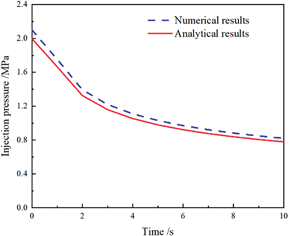
Figure 1: Comparison of numerical results and analytical results
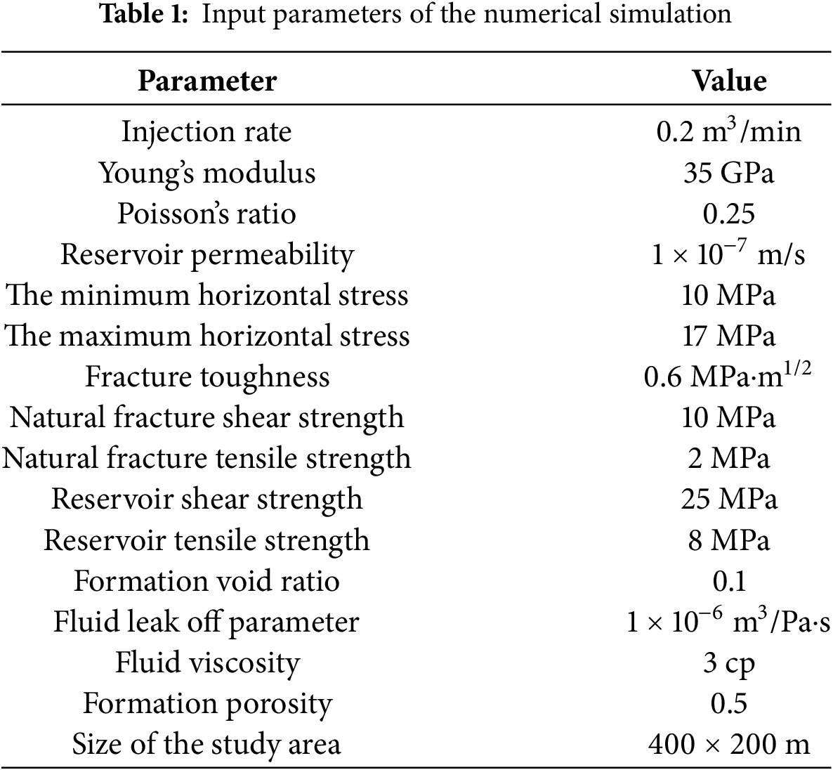
This study constructs a 400 m × 200 m mathematical model. The model integrates three injection points, each corresponding to a crack, and introduces different basic equations of elasticity to describe the complex crack characteristics. The CPE4P seepage stress element and COH2D4P cohesion element were simulated initiation and propagation, respectively. The finite element model first considers the fracture process and mechanical mechanism [24]. The initial natural fracture group (NFs) is affected by the in-situ stress conditions. Fig. 2 shows the construction process of a two-dimensional reservoir model containing two sets of natural fractures. NFs form during specific geological periods, during which the strata undergo multiple tectonic changes. This study uses the three-dimensional finite element method to simulate the stress field and seepage field of complex structures, and sets up an orthogonal conjugate NF network [25]. Most natural fractured reservoirs have more than one set of natural fractures (i.e., a set of fractures with one dominant orientation), and reservoirs containing two sets of natural fractures with different orientations are more common. Usually, the initial set of natural fractures is related to tectonic stress and develops parallel to the compression direction, while the second set of fractures is caused by viscoelastic effects or orthogonal or sub orthogonal loading [26,27]. Calculate the vertical principal stress difference at different orientations and depths based on seismic data, with NFs angles set at 30° and 150°, natural fracture starting length of 0.5 m, the fracture density is 0.4/m. Based on this, calculate the minimum fracture length, opening degree, and other parameters (input parameters are shown in Table 1). Assuming that the initiation and propagation of cracks occur when local stresses exceed the tensile or shear strength of the material, and the process of crack propagation is governed by the nonlinear behavior of the material.
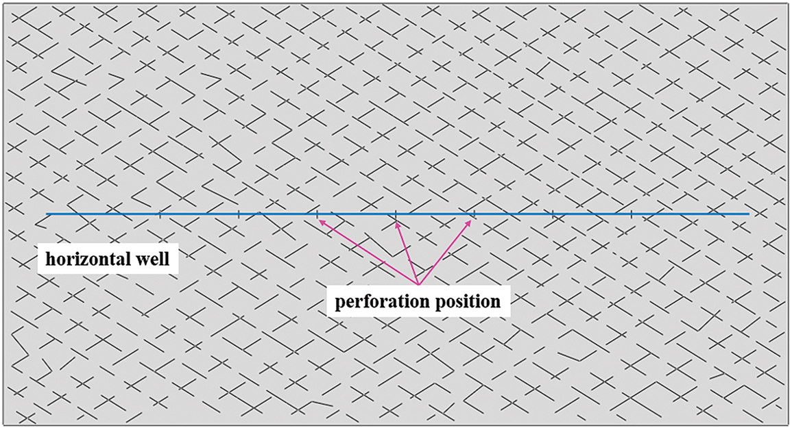
Figure 2: Schematic diagram of a multistaged horizontal fracturing wells in shale gas reservoirs
3.1 Influence of Pumping Rate of Fracturing Fluid on Fracture Propagation
A highly interconnected fracture network can significantly increase the contact area inside the reservoir, expand the flow path of fluids, and thus enhance productivity. Thus, the activation of natural fracture by the hydrualic fracturing is necessary. In addition, reactivated NFs and weak surfaces can cause fluid to divert from the main hydraulic fractures (HFs) channels, leading to issues such as high proppant concentration and premature screening. To conduct in-depth research on the well layout and hydraulic fracturing design of natural fractured tight sandstone reservoirs, a numerical model was constructed in this study [28]. Through this model, the system analyzed the effects of factors such as fracturing fluid pumping rate, fracturing fluid viscosity, elastic modulus, horizontal stress difference, and initial spacing on the crack propagation process. Specifically, this study focuses on simulating the mechanism by which the pumping rate of fracturing fluid affects the formation of fracture networks. Fig. 3 shows the simulated extension path of HFs at different pumping rates. The study set three pumping rates of 0.05, 0.1, and 0.15 m/min, and quantitatively calculated and compared their corresponding crack propagation patterns.
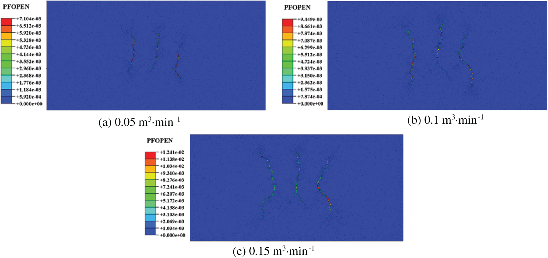
Figure 3: Geometric shape of hydraulic fracture propagation without fracturing fluid pumping rate: (a) Pumping rate of 0.05 m3·min−1; (b) Pumping rate 0.1 m3·min−1; (c) Pumping rate 0.15 m3·min−1
The presence of cemented natural fractures (NFs) can divert the original hydraulic fracture direction, sometimes the propagation trajectory of hydraulic fractures exhibits nonplanar characteristics due to natural fractures slippage. Normally, the evolution of fracture propagation paths is regulated by two opposing forces. On the one hand, materials tend to expand along the fragile interface formed by the NF set; On the other hand, it exhibits a trend of extending along the direction of maximum principal stress. Usually, there is inconsistency between the direction of non local stresses (NFs) and the direction of local principal stresses. During the process of crack propagation, the crack tip needs to balance the effects of these two forces to minimize the fracture energy and tends to travel along the path with the lowest resistance. This phenomenon is precisely the mechanism by which hydraulic fractures (HFs) propagate along a zigzag path [14]. It is worth noting that the geometric configuration of the crack presents a shape characteristic similar to an elbow, and the high-frequency wing parts on both sides exhibit non-uniform motion trajectories. The high-frequency wings on both sides exhibit a directional characteristic of tilting towards the X-axis. Once the pumping rate reaches 0.1 m3/min, the lower wing of the intermediate HF starts to bifurcate. As the pumping rate increases, the upper fracture wing expands more readily. Given the same simulation time, the higher the pumping rate, the more fracturing fluid is pumped, thereby increasing the total fracture length, as depicted in Fig. 4a. Initially, when the pumping rate rises, the total fracture length increases at a relatively fast pace; subsequently, the growth rate slows down. The changes in the formation breakdown pressure are illustrated in Fig. 4b. When the pumping rate was 0.05 m3/min, the formation breakdown pressure was relatively low. As the pumping rate increased, however, the formation breakdown pressure remained essentially the same when the pumping rates were 0.1 and 0.15 m3/min. The higher the pumping rate, the more prominent the zigzag phenomenon becomes, and the more complex the HF structure. When the pumping rate was 0.1 m3/min, the fracture complexity and fracture pressure were largely similar to those at 0.15 m3/min. This indicates that when the pumping rate exceeds 0.1 m3·min−1, the activated NFs and weak surfaces cause fluid to divert from the main HF channel, leaving the HF complexity unchanged. Under the conditions of this model, a pumping rate of 0.1 m3·min−1 is deemed appropriate. As the displacement increases, the complexity of fractures increases and the range of fracturing control expands. However, for hydraulic fracturing operations, increasing the displacement requires higher requirements for wellhead equipment.
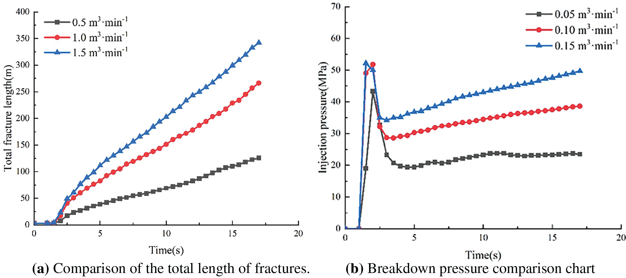
Figure 4: Under different pump speed conditions, a comparative analysis was conducted on the total crack length and rupture pressure, and the specific results are presented as follows: (a) The comparative chart for the total crack length reveals a significant trend of change in crack length with increasing pump speed; (b) The comparison chart of rupture pressure shows the influence mode of pump speed on rupture pressure
3.2 Influence of Viscosity of Fracturing Fluid on Fracture Propagation
The viscosity of pumped fracturing fluid, as a core parameter, has a decisive impact on its effective propagation and fracture generation in the formation. As the viscosity of the fluid increases, the corresponding frictional resistance also increases, leading to a decrease in filtration efficiency, which significantly affects the process of crack formation. Under the premise of keeping all variables constant, crack propagation patterns were calculated and analyzed for fluids with viscosity values of 10, 50, and 100 mPa·s. The results are shown in Fig. 5. When natural fractures (NFs) exist, the propagation path of hydraulic fractures (HFs) deviates from the idealized plane state and exhibits complex geometric distribution characteristics. Compared to the pumping speed, the influence of viscosity on the formation of crack networks is relatively weak. Fig. 6 shows the relationship between the viscosity change of fracturing fluid (from 10 to 50 mPa·s) and the response of total fracture length, and the results show a slight increase trend in total fracture length. In addition, both sides of the crack show an inward trend. The expansion path exhibits a more linear characteristic, and no significant crack development is observed between them. The fracture sites on both sides usually exhibit more linear or right angled features, while the middle fracture area is significantly limited in growth. In this study, we observed that as the viscosity of the fracturing fluid increased from 50 to 100 mPa·s, the three fractures formed exhibited more significant linear characteristics. However, under the condition of 10 mPa·s, the observed total crack length is equal to it, but under a pressure of 50 mPa·s, a smaller total crack length is displayed. As the viscosity of the fracturing fluid decreases, the diverse of the HF can be seen. It is worth noting that in the three specific situations discussed, the initial rupture pressure exhibits a constant state.
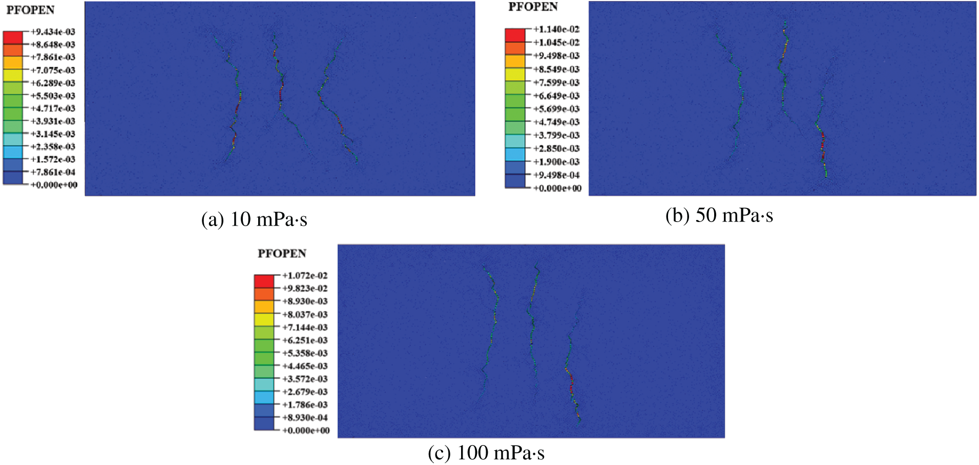
Figure 5: Geometric shape of hydraulic fracture propagation without fracturing fluid viscosity: (a) Fracturing fluid viscosity 10 mPa·s; (b) Fracturing fluid viscosity 50 mPa·s; (c) Fracturing fluid viscosity 100 mPa·s
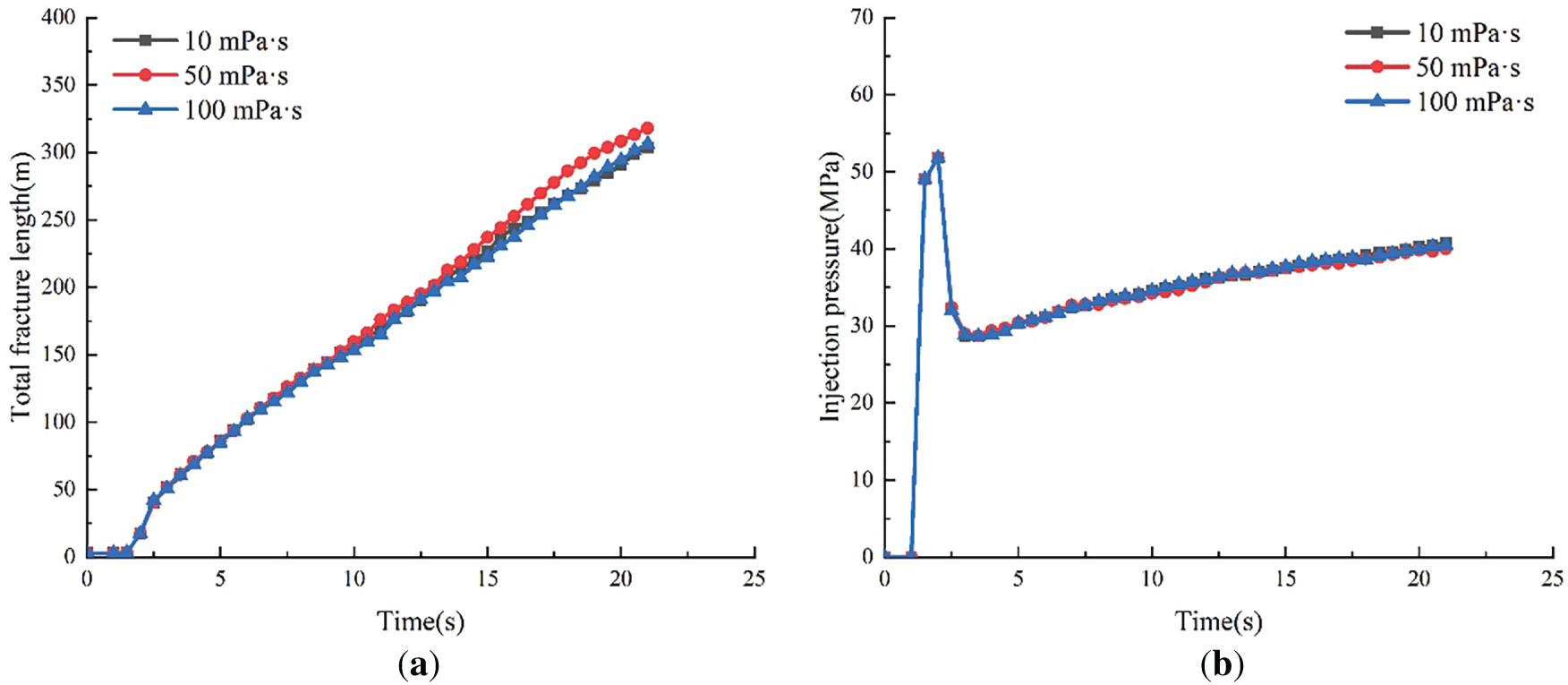
Figure 6: Changes of total fracture length and fracture pressure under different fracturing fluid viscosity: (a) Comparison of total fracture length; (b) Breakdown pressure comparison diagram
This is because as the viscosity of the fracturing fluid increases, hydraulic fracturing (HF) operations tend to penetrate natural fractures (NF) rather than extend along them. This phenomenon is attributed to the enhanced interaction between fluid dynamics and rock media, which promotes the invasion and expansion of natural fractures. In addition, the increase in viscosity of fracturing fluid causes a reduction in the width of fractures near the wellbore area. In addition, the propagation path of the cracks deviates from the direction indicated by the NF set. When the viscosity value of the fracturing fluid exceeds the threshold of 50 mPa·s, the viscosity factor begins to dominate the extension path of the fracture, allowing high-pressure fluid (HF) to penetrate narrow gaps (NF). As the viscosity increases, the constraint on the middle crack weakens, causing the three cracks to tend towards parallel arrangement. This situation significantly exacerbates the process of crack propagation. Accordingly, within the set model framework, the viscosity level of fracturing fluid should be limited to below 100 mPa·s. Compared to the pumping rate, the viscosity of fracturing fluid has a relatively limited impact on the process of crack propagation. The viscosity of fracturing fluid has a relatively small impact on fracture propagation, and a suitable one can be selected according to on-site requirements.
3.3 Influence of Elastic Modulus on Fracture Propagation
This study explores the fracture propagation behavior characteristics of rocks under elastic moduli of 30 gigapascals (GPa) and 40 gigapascals (GPa). Fig. 7 reflects the increase of elastic moduli limit the fracture propagation. On the contrary, its development tends to follow and expand in the direction of natural fissures. In addition, the increase in elastic modulus significantly promotes the nonlinear behavior of the material during the tensile process, manifested as a more pronounced Z-shaped propagation path, an increase in branching cracks, and an overall extension of crack length. As shown in Fig. 8, during the process of increasing the elastic modulus from 20 to 40 GPa, the breakdown pressure shows a significant increasing trend. The comparison between Fig. 7b,c reveals that as the elastic modulus increases, the expansion of the middle crack and the upper area of the right crack is significantly suppressed. As the elastic modulus increases, the compression state of the surrounding strata of hydraulic fractures exhibits significant heterogeneity characteristics. At the tip of hydraulic fracture branches and their adjacent areas, as well as at the tip of activated natural fractures and their surrounding areas, the geological material is in a state of tensile stress. The simulation results show that the increase in elastic modulus significantly enhances the complexity of hydraulic crack propagation and increases its likelihood of intersecting with natural cracks. The stress effect significantly intensifies around the extension area of hydraulic fractures. Under normal circumstances, the strength of sandstone reservoirs is directly proportional to their elastic modulus, which in turn determines the significant increase in pressure threshold that the formation can withstand when it fractures. The results show that as the elastic modulus increases, the fracture length increases and the number of branch cracks decreases, which is consistent with the experimental results of rock mechanics fracturing that the larger the elastic modulus, the greater the rock brittleness, and the easier it is to form long fractures.
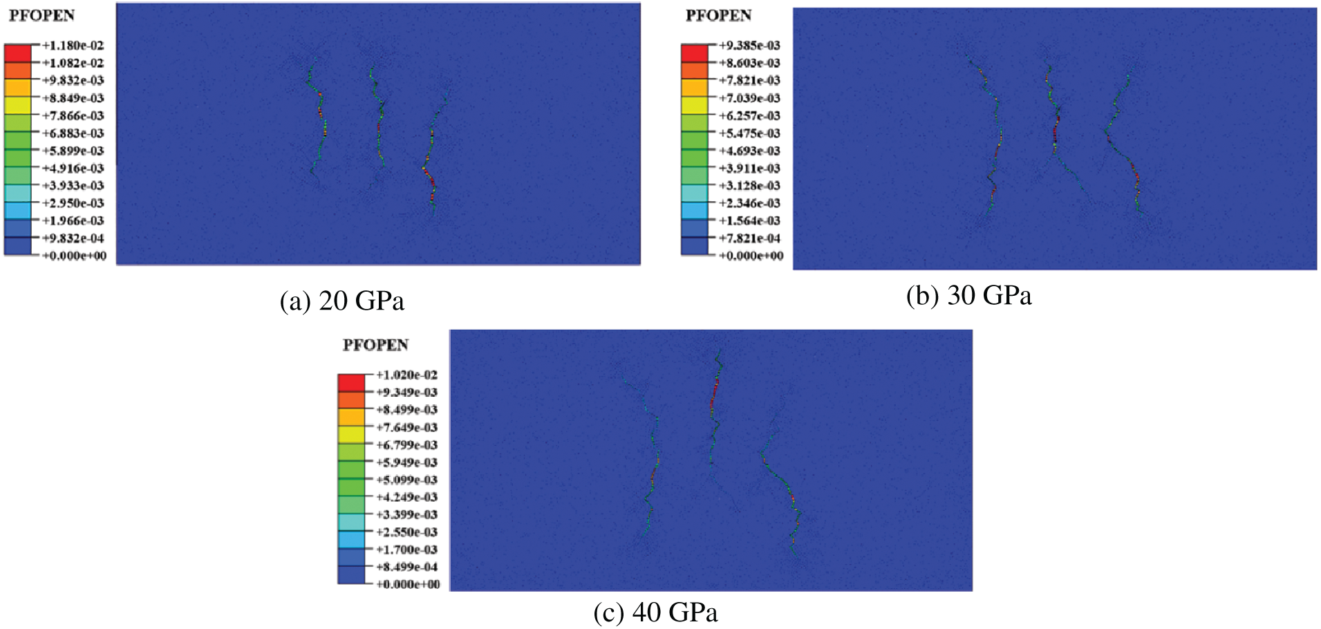
Figure 7: Geometric shape of hydraulic fracture propagation without elastic modulus: (a) Elastic modulus of 20 GPa; (b) Elastic modulus of 30 GPa; (c) Elastic modulus of 40 GPa
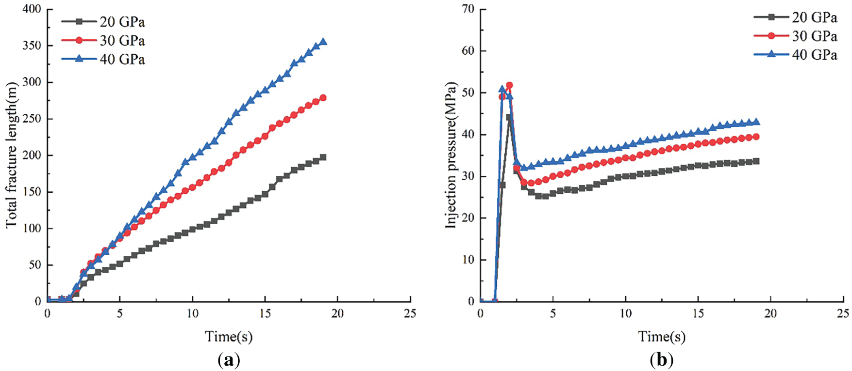
Figure 8: Changes of total fracture length and fracture pressure under different elastic moduli: (a) Comparison of total fracture length; (b) Breakdown pressure comparison diagram
3.4 Influence of Different Horizontal Stress Differences on Fracture Propagation
Numerical simulations were conducted within the pressure range of 5 megapascals to 10 megapascals. As shown in Fig. 9, within the pressure gradient range of 0–10 MPa, it was observed that the complexity of cracks showed a decreasing trend with increasing horizontal stress differences. According to simulation analysis, when the difference in horizontal stress decreases, the turning and expansion of hydraulic fractures show an advanced phenomenon. This phenomenon is attributed to the combined effect of natural fracture networks and in-situ stress states. As the principle horizontal stress difference increases, cracks tend to develop along the direction of the maximum horizontal principal stress [29]. When the horizontal stress difference reaches 10 megapascals, the crack exhibits a nearly parallel feature to the Y-axis direction. In this context, the difference in horizontal stress actually dominates the extension path of cracks, causing the development of cracks to deviate from their original natural direction and exhibit specific directional expansion characteristics. Although the complexity of fractures is lower under high stress differences, the total fracture length significantly increases due to the easier penetration of fracturing fluid into the formation.
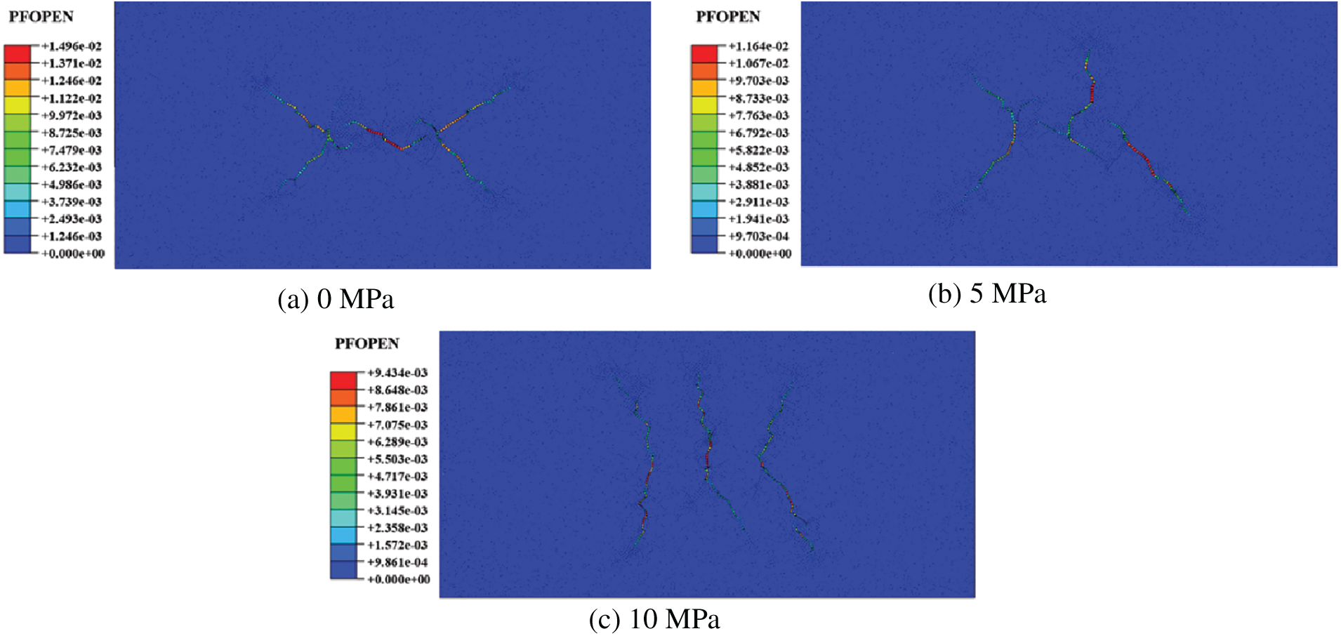
Figure 9: Geometric shapes of hydraulic fracture propagation under different horizontal geo stress differences: (a) HSD = 0 MPa; (b) HSD = 5 MPa; (c) HSD = 10 MPa
The occurrence of this phenomenon is attributed to the geometric characteristics of the natural fracture network and its interaction with the direction of the maximum horizontal stress in the formation, both of which collectively determine the propagation path and scale of hydraulically induced fractures. Under the condition of zero stress differential, the primary propagation path of hydraulic fractures tends to follow the natural fracture network, specifically manifesting as an extension along the approximate directions of 45° and 135°. As the stress differential increases, the influence of these two factors tends to balance, as visually represented in Fig. 9b. For instance, it is observed that the bottom of the intermediate fracture significantly aligns with the direction of the natural fractures, while its top exhibits a tendency to traverse the natural fractures. The intense “stress shadow” effects affect the complex fracture geometries and tight perforation spacing is beneficial for fracture complexity. This simulation found that when the ground stress difference was 0, it did not make the fracture morphology more complex. As shown in Fig. 10, with the increase of HSD, the total length of fractures increases and the rupture pressure decreases. It is speculated that the propagation of fracturing fractures is influenced by multiple factors, especially the distribution of natural fractures. The change in the direction of fracture propagation caused by the ground stress difference, combined with the distribution of natural fractures along the propagation path, affects the final fracture propagation morphology.
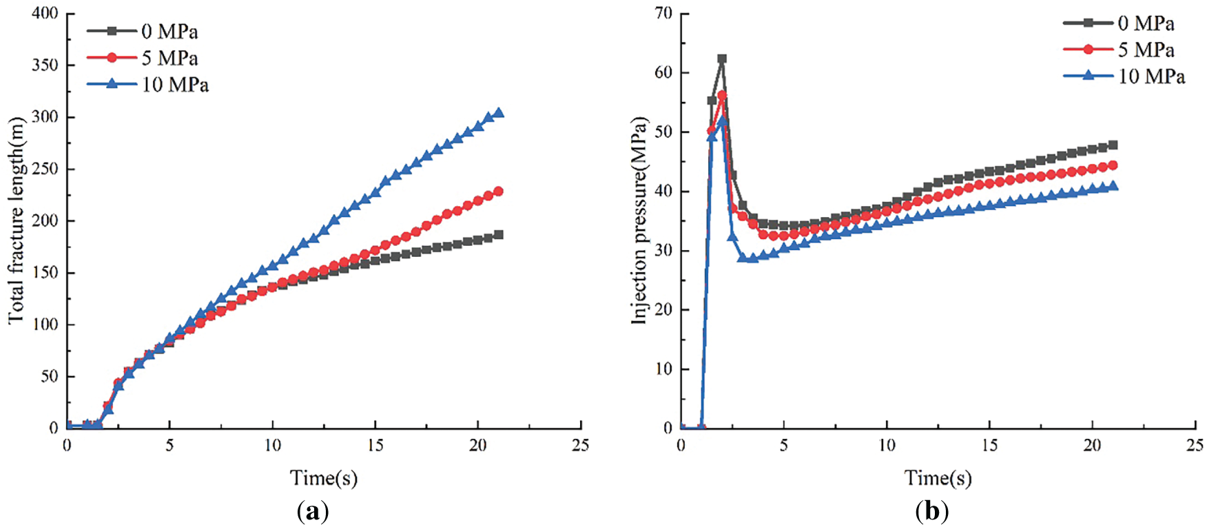
Figure 10: Changes of total fracture length and fracture pressure under different horizontal geo stress differences: (a) Comparison of total fracture length; (b) Breakdown pressure comparison diagram
3.5 Influence of Fracturing Perforation Spacing on Fracture Propagation
Under the condition of keeping all other factors constant, this study systematically analyzed the crack propagation patterns at different cluster spacings (namely 20, 40, and 60 m) [30]. According to the data analysis shown in Fig. 11, as the distance between fracturing stages increases, the effect of the intermediate fractures on adjacent fractures shows a diminishing trend, leading to a more pronounced extension characteristic of hydraulic fractures under the influence of the maximum horizontal principal stress. As illustrated in Fig. 12, when the cluster spacing increases from 20 to 40 m, and then to 60 m, the total fracture length remains constant, revealing that the increase in cluster spacing does not result in the anticipated variation in fracture length. However, given the weakened interaction between hydraulic fractures, the formation of branching fractures in the central region is limited at larger spacings, leading to a relative decrease in the total fracture length, and thus the overall fracture length shows a declining trend. The peak breakdown pressure observed at the 20-m spacing is primarily attributed to significant interaction effects. In the analysis, it was found that when the distance exceeds 40 and 60 m, the breakdown pressure reaches a stable level, indicating that beyond this range, the difference in cluster spacing no longer significantly affects the breakdown pressure. Furthermore, as the fracturing operation continues, regardless of the initial conditions, the breakdown pressure of fractures in all three models shows a convergent trend. This phenomenon occurs because the fracture tips gradually surpass the near-wellbore region, making the spacing between stages no longer significantly influence the fracture propagation process. Within the described framework, the formation and extension process of hydraulic fractures are constrained by the cluster spacing, with the key role of the cluster spacing being to guide the direction of fracture propagation. However, significant spacing leads to a weakening of the interaction between fractures, thereby reducing the cumulative length of the overall fractures. Although increasing the spacing helps to form a more complex hydraulic fracture network with good connectivity to natural fractures, in practice, the structural feasibility and economic costs of this strategy must also be weighed. The larger the spacing between holes, the smaller the stress interference, and it is necessary to optimize the spacing, which is also the research to be carried out in the future.
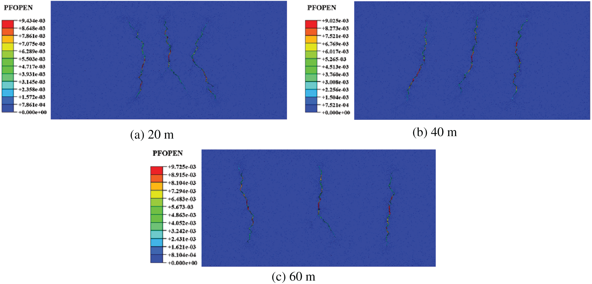
Figure 11: Geometric shapes of hydraulic fracture propagation under different stage spacing: (a) Stage spacing of 20 m; (b) Stage spacing of 40 m; (c) Stage spacing of 60 m
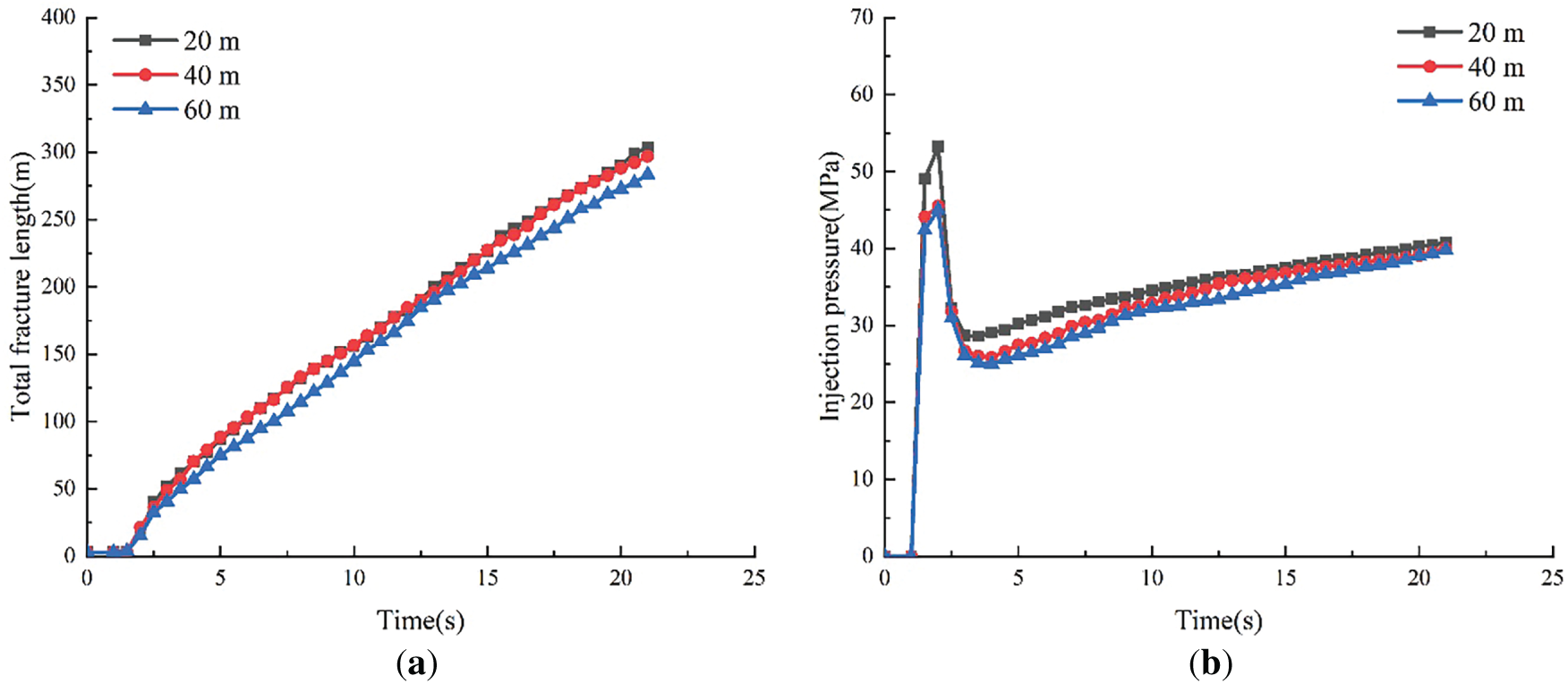
Figure 12: Variation diagram of total fracture length and fracture pressure under different stage spacing: (a) Comparison of total fracture length; (b) Breakdown pressure comparison diagram
Large-scale stimulated reservoir volume (SRV) fracturing is widely acknowledged as a critical technique for enhancing tight reservoirs, as it creates a complex network of interconnected fracture channels within the SRV, significantly increasing the reservoir contact area. In the described simulation study, the control variable method was employed to delve into the critical parameters and environmental conditions necessary for the complex fracture networks creation in naturally fractured tight sandstone reservoirs. This research focuses on five core variables to explore their impact on the efficacy of fracturing operations: the pumping rate of the fracturing fluid, the viscosity of the fracturing fluid, the elastic modulus, the gradient of horizontal in-situ stress, and the spacing between fracturing stages. In summary, the elastic modulus, the differential in horizontal in-situ stress, and the pumping rate have the most significant influence on determining the propagation process of the hydraulic fracture network. However, despite the experimental simulations indicating the presence of natural fractures in the reservoir, they failed to generate the anticipated complex fracture network structure. Among the findings, the configuration with zero differential in-situ stress came closest to producing a complex fracture network pattern. The absence of such a network can be attributed to the effects of stress shadowing and fluid resistance [31]. When the spacing between perforation clusters is too small, the propagation of fractures initiated by the central clusters is significantly restricted during the injection of the pad fluid, whereas fractures near the ends tend to disperse. Once the initial natural fractures form and exert pressure on the surrounding artificial hydraulic fractures, it may cause these fractures to deviate from the intended direction, inhibit their further propagation, and promote fracture closure under localized pressure increases. Additionally, interactions between multiple major fractures, as demonstrated in the stage spacing simulations, further complicate fracture propagation. Once a dominant fracture forms, the hydraulic fracturing paths in the near-well zone become more complex than those in the far-well zone. Moreover, if natural fractures are poorly connected to hydraulic fractures, their contribution to reservoir stimulation is minimal [32,33].
Fracture propagation paths in naturally fractured reservoirs are inherently complex and asymmetrically developed. However, these characteristics do not necessarily lead to the formation of well-branched, tree-like fracture networks at various levels. The principal branches of hydraulic fractures serve as essential conduits for fluid flow. Owing to the synergistic influence of stress shadow effects, fluid resistance, and unfavorable propagation orientations, the subsidiary branches of hydraulic fractures frequently curtail their growth trajectory following a transient period of elongation, or they may progressively converge towards closure. In naturally fractured reservoirs, “complex fractures” are more common than “fracture networks”, unless pre-existing natural fractures or weak surfaces have already established a network-like structure. The simulation results indicate that forming complex fractures is easier than creating complex fracture networks. However, this study employed the control variable method, altering only one factor at a time. In the conducted research, a comprehensive consideration of multiple key parameters was undertaken, including the reduction of the spacing between fracturing stages, the selection of an appropriate pumping rate, the adjustment of fluid viscosity and elastic modulus, as well as ensuring the differential in-situ stress is nullified. These measures have significantly enhanced the potential to construct a highly complex fracture network structure in numerical simulations. This approach will be further explored in future research. Therefore, more detailed simulations are needed to accurately capture the behavior of hydraulic fractures under these combined conditions.
The migration, accumulation, and high-yield potential of hydrocarbons in such reservoirs are closely tied to the natural fracture systems within them. Large-scale fracture networks not only enhance reservoir seepage capacity but also significantly influence effective productivity, post-fracturing optimization, and reservoir development design strategies. This research delves into the regulatory effects of rock mechanical properties, in-situ stress evolution, and engineering-related parameters on the structural features of fracture networks. The following conclusions were drawn:
(1) Once the pumping rate exceeds the threshold of 0.1 m per minute, the activated natural fractures and weak interfaces facilitate the diversion of fluid to paths outside the main hydraulic fracture, while the geometric complexity of the hydraulic fracture remains unchanged. When the viscosity of the applied fracturing fluid is increased, the resulting hydraulic fractures tend to traverse the existing natural fracture network rather than merely extending along its path, a phenomenon that reveals the significant influence of fluid properties on the formation modification process. A reduction in the width of fractures near the wellbore can be observed using low viscous fracturing fluid and may cause fracture deviation when interacts with natural fractures.
(2) The elastic modulus significantly affects the total fracture length of the material. If the elastic modulus is low, the hydraulically induced fractures tend to penetrate the naturally existing fracture structures, which is actually detrimental to the expected hydraulic fracture propagation and formation process.
(3) As the differential in horizontal stress increases, the total fracture length of the system shows an upward trend, while the breakdown pressure exhibits a decreasing phenomenon. A higher gradient of horizontal stress significantly promotes the initial formation of hydraulic fractures. In the case of zero stress differential, the crack initiation angles observed in the two sets of experiments are approximately 45° and 135°, respectively. The crack propagation paths display a high degree of complexity and form a characteristic “X-shaped” fracture pattern.
(4) As the stress differential increases, the direction of fracture propagation gradually aligns with the axis of the maximum horizontal principal stress. When the horizontal stress differential reaches 10 MPa, the fractures tend to develop nearly parallel to the Y-axis. In this scenario, the horizontal stress differential almost entirely dictates the direction of fracture propagation, with the fracture extension trajectory rarely following the path of natural fractures.
(5) The development and propagation of hydraulic fractures are governed by the spacing between fracturing operation stages, a parameter that significantly influences the path of fracture extension. Nevertheless, an excessively large spacing will reduce the mutual interaction between fractures, leading to a decrease in the total fracture length. In future research, simultaneous variations of multiple factors will be taken into account to identify the optimal combination for forming complex fracture networks in three-dimensional space.
Although extending the global embedding cohesive force model to a three-dimensional model faces some challenges, especially in terms of computational complexity and spatial description of cohesive force effects, with the improvement of computing power and the development of numerical methods, three-dimensional extension is feasible and has broad application prospects.
Acknowledgement: Not applicable.
Funding Statement: This work has been financially supported by the National Natural Science Foundation of China (52074313).
Author Contributions: The authors confirm contribution to the paper as follows: study conception and design: Zhengrong Chen, Yu Qi; data collection: Maojun Fang, Bo Wang; analysis and interpretation of results: Xin Xie; draft manuscript preparation: Le Sun, Wei Liu. All authors reviewed the results and approved the final version of the manuscript.
Availability of Data and Materials: Due to the nature of this research, participants of this study did not agree for their data to the shared publicly, so supporting data is not available.
Ethics Approval: Not applicable.
Conflicts of Interest: The authors declare no conflicts of interest to report regarding the present study.
References
1. Olson JE, Laubach SE, Eichhubl P. Estimating natural fracture producibility in tight gas sandstones: coupling diagenesis with geomechanical modeling. Lead Edge. 2010;29(12):1494–9. doi:10.1190/1.3525366. [Google Scholar] [CrossRef]
2. Zeng L, Lyu W, Li J, Zhu L, Weng J, Yue F, et al. Natural fractures and their influence on shale gas enrichment in Sichuan Basin. China J Nat Gas Sci Eng. 2016;30(5):1–9. doi:10.1016/j.jngse.2015.11.048. [Google Scholar] [CrossRef]
3. Lyu W, Zeng L, Zhang B, Miao F, Lyu P, Dong S. Influence of natural fractures on gas accumulation in the Upper Triassic tight gas sandstones in the northwestern Sichuan Basin. China Mar Petrol Geol. 2017;83(12):60–72. doi:10.1016/j.marpetgeo.2017.03.004. [Google Scholar] [CrossRef]
4. Fisher MK, Wright CA, Davidson BM, Goodwin AK, Fielder EO, Buckler WS, et al. Integrating fracture mapping technologies to optimize stimulations in the Barnett shale. In: Proceedings of the SPE Annual Technical Conference and Exhibition; 2022 Sep 29–Oct 2; San Antonio, TX, USA. Richardson, TX, USA: SPE; 2002. SPE-77441-MS. doi:10.2118/77441-ms. [Google Scholar] [CrossRef]
5. Wang WD, Su YL, Zhang Q, Xiang G, Cui SM. Performance-based fractal fracture model for complex fracture network simulation. Pet Sci. 2018;15(1):126–34. doi:10.1007/s12182-017-0202-1. [Google Scholar] [CrossRef]
6. Maxwell SC, Urbancic TI, Steinsberger N, Zinno R. Microseismic imaging of hydraulic fracture complexity in the Barnett shale. In: Proceedings of the SPE Annual Technical Conference and Exhibition; 2022 Sep 29–Oct 2; San Antonio, TX, USA. Richardson, TX, USA: SPE; 2002. SPE-77440-MS. doi:10.2118/77440-ms. [Google Scholar] [CrossRef]
7. Shiu W, Guglielmi Y, Graupner B, Rutqvist J. Modelling the water injection induced fault slip and its application to in situ stress estimation. Int J Rock Mech Min Sci. 2021;137(7):104537. doi:10.1016/j.ijrmms.2020.104537. [Google Scholar] [CrossRef]
8. Gu H, Weng X. Criterion for fractures crossing frictional interfaces at nonorthogonal angles. In: Proceedings of the 44th US Rock Mechanics Symposium and 5th US-Canada Rock Mechanics Symposium; 2010 Jun 27–30; Salt Lake City, UT, USA. Nevada City, CA, USA: ARMA; 2010. ARMA-10-198. doi:10.2118/139984-PA. [Google Scholar] [CrossRef]
9. Tan P, Jin Y, Han K, Hou B, Chen M, Guo X, et al. Analysis of hydraulic fracture initiation and vertical propagation behavior in laminated shale formation. Fuel. 2017;206(2):482–93. doi:10.1016/j.fuel.2017.05.033. [Google Scholar] [CrossRef]
10. Zhang H, Sheng JJ. Numerical simulation and optimization study of the complex fracture network in naturally fractured reservoirs. J Petrol Sci Eng. 2020;195(5):107726. doi:10.1016/j.petrol.2020.107726. [Google Scholar] [CrossRef]
11. Rui Z, Guo T, Feng Q, Qu Z, Qi N, Gong F. Influence of gravel on the propagation pattern of hydraulic fracture in the glutenite reservoir. J Petrol Sci Eng. 2018;165(5):627–39. doi:10.1016/j.petrol.2018.02.067. [Google Scholar] [CrossRef]
12. Zhang G, Sun S, Chao K, Niu R, Liu B, Li Y, et al. Investigation of the nucleation, propagation and coalescence of hydraulic fractures in glutenite reservoirs using a coupled fluid flow-DEM approach. Powder Technol. 2019;354:301–13. doi:10.1016/j.powtec.2019.05.073. [Google Scholar] [CrossRef]
13. Zhang X, Si G, Bai Q, Xiang Z, Li X, Oh J, et al. Numerical simulation of hydraulic fracturing and associated seismicity in lab-scale coal samples: a new insight into the stress and aperture evolution. Comput Geotech. 2023;160(84):105507. doi:10.1016/j.compgeo.2023.105507. [Google Scholar] [CrossRef]
14. Wang H. Hydraulic fracture propagation in naturally fractured reservoirs: complex fracture or fracture networks. J Nat Gas Sci Eng. 2019;68(2):102911. doi:10.1016/j.jngse.2019.102911. [Google Scholar] [CrossRef]
15. Wei YS, Wang JL, Yu W, Qi YD, Miao JJ, Yuan H, et al. A smart productivity evaluation method for shale gas wells based on 3D fractal fracture network model. Petrol Explor Dev. 2021;48(4):787–96. (In Chinese). doi:10.1016/s1876-3804(21)60076-9. [Google Scholar] [CrossRef]
16. Li J, Dong S, Hua W, Li X, Pan X. Numerical investigation of hydraulic fracture propagation based on cohesive zone model in naturally fractured formations. Processes. 2019;7(1):28. doi:10.3390/pr7010028. [Google Scholar] [CrossRef]
17. Imran M, Wang D, Wang L, Abdel Wahab M. Finite element modelling of effect of corrosion on fretting wear in steel wires. Tribol Int. 2025;206(13):110573. doi:10.1016/j.triboint.2025.110573. [Google Scholar] [CrossRef]
18. Zheng M, Chen W, Yan X, Liu Z, Abdel Wahab M. Finite element analysis of bolted joints under torsional loads. Tribol Int. 2025;201:110188. doi:10.1016/j.triboint.2024.110188. [Google Scholar] [CrossRef]
19. Sobhaniaragh B, Mansur WJ, Peters FC. Three-dimensional investigation of multiple stage hydraulic fracturing in unconventional reservoirs. J Petrol Sci Eng. 2016;146(7):1063–78. doi:10.1016/j.petrol.2016.07.019. [Google Scholar] [CrossRef]
20. Khoei AR, Vahab M, Ehsani H, Rafieerad M. X-FEM modeling of large plasticity deformation; a convergence study on various blending strategies for weak discontinuities. Eur J Comput Mech. 2015;24(3):79–106. doi:10.1080/17797179.2015.1083516. [Google Scholar] [CrossRef]
21. Lopes Fernandes R, Teixeira de Freitas S, Budzik MK, Poulis JA, Benedictus R. Role of adherend material on the fracture of bi-material composite bonded joints. Compos Struct. 2020;252(1–3):112643. doi:10.1016/j.compstruct.2020.112643. [Google Scholar] [CrossRef]
22. Huang L, Liu J, Zhang F, Fu H, Zhu H, Damjanac B. 3D lattice modeling of hydraulic fracture initiation and near-wellbore propagation for different perforation models. J Petrol Sci Eng. 2020;191:107169. doi:10.1016/j.petrol.2020.107169. [Google Scholar] [CrossRef]
23. Yang L, Chen B. Extended finite element-based cohesive zone method for modeling simultaneous hydraulic fracture height growth in layered reservoirs. J Rock Mech Geotech Eng. 2024;16(8):2960–81. doi:10.1016/j.jrmge.2023.12.012. [Google Scholar] [CrossRef]
24. Zhou J, Zhang L, Pan Z, Han Z. Numerical studies of interactions between hydraulic and natural fractures by Smooth Joint Model. J Nat Gas Sci Eng. 2017;46(B6):592–602. doi:10.1016/j.jngse.2017.07.030. [Google Scholar] [CrossRef]
25. Sheng M, Cheng SZ, Lu ZH, Zhang Y, Tian SC, Li GS. Influence of formation in situ stress on mechanical heterogeneity of shale through grid nanoindentation. Petrol Sci. 2022;19(1):211–9. doi:10.1016/j.petsci.2021.10.006. [Google Scholar] [CrossRef]
26. Ranjith PG, Zhang CP, Zhang ZY. Experimental study of fracturing behaviour in ultralow permeability formations: a comparison between CO2 and water fracturing. Eng Fract Mech. 2019;217(6):106541. doi:10.1016/j.engfracmech.2019.106541. [Google Scholar] [CrossRef]
27. Han L, Shi X, Ni HJ, Zhang WD, Ge XX, Yang YY, et al. Optimization of supercritical CO2 fracturing based on random forest-particle swarm optimization model and pre-existing fracture network. SPE J. 2024;29(11):5957–75. doi:10.2118/223585-pa. [Google Scholar] [CrossRef]
28. Han L, Shi X, Ni H, Jiang S, Che M, Qu F. Fracture toughness evaluation of shale based on machine learning and micromechanical approach. Eng Fract Mech. 2025;323(1):111194. doi:10.1016/j.engfracmech.2025.111194. [Google Scholar] [CrossRef]
29. An M, Zhang F, Dontsov E, Elsworth D, Zhu H, Zhao L. Stress perturbation caused by multistage hydraulic fracturing: implications for deep fault reactivation. Int J Rock Mech Min Sci. 2021;141(5):104704. doi:10.1016/j.ijrmms.2021.104704. [Google Scholar] [CrossRef]
30. Liao S, Hu J, Zhang Y. Investigation on the influence of multiple fracture interference on hydraulic fracture propagation in tight reservoirs. J Petrol Sci Eng. 2022;211(5):110160. doi:10.1016/j.petrol.2022.110160. [Google Scholar] [CrossRef]
31. Warpinski NR, Teufel LW. Influence of geologic discontinuities on hydraulic fracture propagation (includes associated papers 17011 and 17074). J Petrol Technol. 1987;39(2):209–20. doi:10.2118/13224-pa. [Google Scholar] [CrossRef]
32. Wang H, Sharma MM. New variable compliance method for estimating closure stress and fracture compliance from DFIT data. In: Proceedings of the SPE Annual Technical Conference and Exhibition; 2017 Oct 9–11; San Antonio, TX, USA. [cited 2025 Jun 16]. Available from: https://onepetro.org/ARMAUSRMS/proceedings/ARMA18/ARMA18/ARMA-2018-225/122456?searchresult=1 [Google Scholar]
33. Wu K, Olson JE. Numerical investigation of complex hydraulic-fracture development in naturally fractured reservoirs. SPE Prod Oper. 2016;31(4):300–9. doi:10.2118/173326-pa. [Google Scholar] [CrossRef]
Cite This Article
 Copyright © 2026 The Author(s). Published by Tech Science Press.
This work is licensed under a Creative Commons Attribution 4.0 International License , which permits unrestricted use, distribution, and reproduction in any medium, provided the original work is properly cited.
 Downloads
 Citation Tools