
 Submit a Paper
 Propose a Special lssue
 Open Access
ARTICLE

Optimum Operation of Low-Voltage AC/DC Distribution Areas with Embedded DC Interconnections under Three-Phase Unbalanced Compensation Conditions
1 Electric Power Research Institute of Guizhou Power Grid Co., Ltd., Guiyang, 550002, China
2 XJ Electric Co., Ltd., Xuchang, 461000, China
* Corresponding Author: Jikai Li. Email:
(This article belongs to the Special Issue: Construction and Control Technologies of Renewable Power Systems Based on Grid-Forming Energy Storage)
Energy Engineering 2026, 123(3), 4 https://doi.org/10.32604/ee.2025.069610
Received 26 June 2025; Accepted 06 August 2025; Issue published 27 February 2026
 View Full Text
 Download PDF
Abstract
This paper presents an optimal operation method for embedded DC interconnections based on low-voltage AC/DC distribution areas (EDC-LVDA) under three-phase unbalanced compensation conditions. It can optimally determine the transmission power of the DC and AC paths to simultaneously improve voltage quality and reduce losses. First, considering the embedded interconnected, unbalanced power structure of the distribution area, a power flow calculation method for EDC-LVDA that accounts for three-phase unbalanced compensation is introduced. This method accurately describes the power flow distribution characteristics under both AC and DC power allocation scenarios. Second, an optimization scheduling model for EDC-LVDA under three-phase unbalanced conditions is developed, incorporating network losses, voltage quality, DC link losses, and unbalance levels. The proposed model employs an improved particle swarm optimization (IPSO) two-layer algorithm to autonomously select different power allocation coefficients for the DC link and AC section under various operating conditions. This enables embedded economic optimization scheduling while maintaining compensation for unbalanced conditions. Finally, a case study based on the IEEE 13-node system for EDC-LVDA is conducted and tested. The results show that the proposed optimal operation method achieves a 100% voltage compliance rate and reduces network losses by 13.8%, while ensuring three-phase power balance compensation. This provides a practical solution for the modernization and upgrading of low-voltage power grids.Keywords
With the promotion of low-carbon power systems, a significant number of distributed photovoltaic systems are being integrated into rural distribution networks. The output of photovoltaic systems is characterized by strong randomness and intermittency, and a high level of integration on the low-voltage side worsens the imbalance of the three-phase distribution network, leading to issues such as unbalanced feeder loads, frequent voltage fluctuations that exceed limits, and reverse power flows [1–4]. Embedded direct current interconnections (EDC) use flexible power electronics technology to create direct current links within traditional AC distribution areas, effectively addressing challenges related to dynamic capacity expansion and power quality in distribution networks, making it a promising direction for future flexible distribution networks [5,6].
The EDC-based low-voltage distribution areas (EDC-LVDA) consist of two types: interconnections between multiple areas and interconnections within a single area. These use AC-DC voltage source converters (VSC) to enhance power supply capabilities and improve power quality in distribution areas [7]. The interconnection between areas focuses on solving load balancing issues among different area transformers, while the interconnection within an area aims to manage low voltage at the end of the area, enable dynamic capacity expansion, and address three-phase imbalance issues [8,9]. However, commonly used three-phase three-leg (3P3L) VSCs have limited ability to handle asymmetric and non-linear loads, which prevents effective compensation of three-phase unbalanced power. Conversely, the three-phase four-leg (3P4L) VSC-based EDC-LVDC includes a separately controllable fourth leg that allows for independent control of each phase’s power, providing an effective solution for three-phase unbalance compensation in low-voltage distribution areas [10,11].
The EDC-LVDC provides a DC path for power transmission, and the transmission power of the DC path will have a significant impact on the system’s voltage distribution, loss characteristics, etc. Reasonable optimal regulation of the power in this DC path is crucial to ensuring the high power quality and highly reliable operation of EDC-LVDA. References [12,13] present a multi-time-scale optimization scheduling scheme for a flexible interconnected distribution network that integrates SOP and VSC technologies. Reference [14] proposes an optimization scheduling model for AC-DC low-voltage distribution networks based on multi-mode flexible interconnection, using convex optimization theory for model convexification and linearization. Reference [15] addresses the issue of source-load uncertainty in flexible interconnected distribution networks by proposing an optimization scheduling method based on improved model predictive control. Reference [16] introduces a comprehensive regulation strategy for three-phase imbalance and heavy-light load operation issues in flexible interconnected distribution areas, based on a four-bridge-arm intelligent soft switch, to meet the demands for comprehensive governance of these problems. However, previous research primarily focuses on load balancing power scheduling for interconnection between multiple distribution areas, with little attention given to interconnection scheduling within a single distribution area. Particularly under three-phase imbalance conditions, the imbalance scheduling commands for VSCs within the distribution area can significantly affect the distribution characteristics of the power flow, necessitating the establishment of a power flow calculation model and an optimization scheduling method that takes into account the management of three-phase imbalance conditions within the distribution area.
To address these issues, this paper proposes an optimum operation of EDC-LVDA under three-phase unbalanced compensation conditions, which can optimally determine the transmission power of the DC and AC path to simultaneously achieve optimization of voltage quality and losses. Firstly, a power flow calculation method for EDC-LVDA under three-phase imbalance compensation conditions is proposed, which considers the power flow distribution characteristics. Secondly, under three-phase unbalanced conditions, an optimization scheduling model for flexible low-voltage distribution areas is constructed, incorporating network losses, voltage quality, DC circuit losses, and imbalance levels. The Improved particle swarm optimization (IPSO) algorithm is employed to adaptively select the power distribution coefficients for DC and AC paths under different operating conditions, achieving embedded economic optimization scheduling while ensuring compensation for imbalance conditions. The potential applications of this method focus on urban and rural low-voltage distribution networks, renovation of aging power grids, and AC/DC hybrid microgrids. It can solve three-phase unbalance issues, improve voltage stability, reduce network losses, adapt to the integration of distributed energy resources, and is suitable for scenarios with large load fluctuations or in need of upgrading.
The paper is organized as follows: the second part of this paper introduces the operation of 3P4L-based EDC-LVDA under unbalanced compensation conditions. The third part introduces the power flow calculation method for EDC-LVDA under unbalanced compensation conditions. The fourth part introduces a scheduling optimization strategy for EDC-LVDA. The fifth part presents the case study analysis, and the sixth part is the conclusion of this paper.
2 Operation of EDC-LVDA under Unbalanced Compensation Conditions
Fig. 1 shows the basic structure of EDC-LVDA. At both the beginning and the end of the distribution area, VSC converters are used to construct embedded DC links, enabling dynamic capacity expansion of the original AC distribution area and compensating for the three-phase imbalance of the distribution transformers in the area. The connections of different PVs and loads are unordered, and not all of them are three-phase symmetric connections, which is also the reason for the three-phase imbalance in the distribution network. To achieve the three-phase compensation of the AC area, the VSC uses the 3P4L-based VSC, its topology is plotted in Fig. 1. The typical operation of the EDC-LVDA can be described as follows:
1. The VSC1 at the beginning is responsible for controlling the DC bus voltage of the embedded DC link, allowing for flexible routing of power between the source and the load.
2. The VSC2 at the tail end outputs a precise phase-shifted signal based on the power signal received from the head end, which uses a split-phase active and reactive power control to achieve compensation for three-phase power imbalances. The details operation of active and reactive power control can be found in reference to [17].
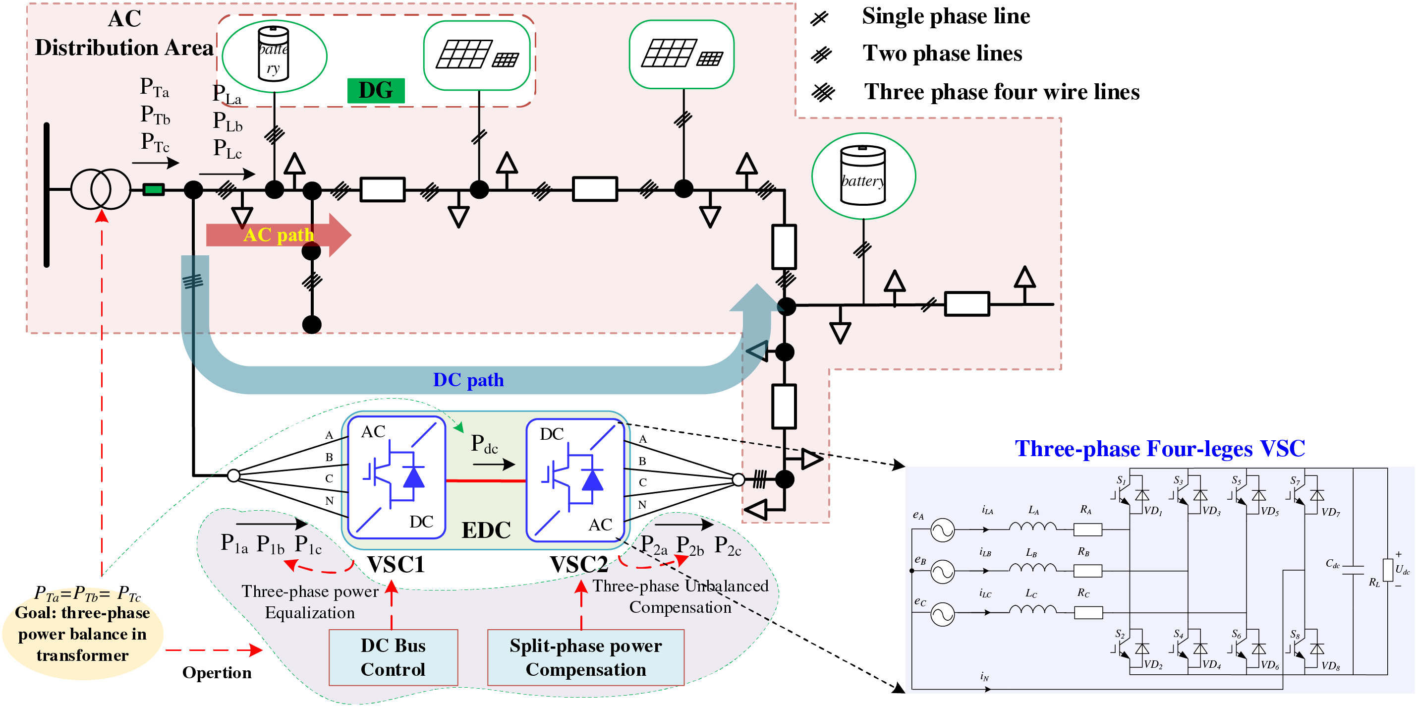
Figure 1: The basic structure and operation of EDC-LVDA
The embedded DC link not only compensates for unbalanced power but also enables dynamic capacity expansion of the AC area, providing a new energy routing channel for the power loads in the area. The power processed by the DC-links will affect the voltage quality and power loss of the whole distribution area, thus the power analysis is presented.
The goal of the EDC-LVDA is to achieve three-phase power balance in transformers, thus can be obtained as
where PTi (i = a, b, c) is each phase power at the input transformer, PLi (i = a, b, c) is each phase load, which is unbalanced due to the strong randomness and intermittency of the load and PVs. Ploss is the power loss of the whole EDC-LVDA system.
Defining the power distribution ratio k (0 < k < 1) to stand for the ratio of the power processed by the EDC path that accounts for the total power, i.e.,
where P1i (i = a, b, c) is each phase power for VSC1. Thus, the power of the EDC Pdc can be obtained as
where ptotal is the total power of the loads in EDC-LVDA.
VSC2 is using the split-phase active and reactive power control to compensate for the load unbalance for each phase, thus the following stages can be obtained as
where P2i (i = a, b, c) is each phase power for VSC2, which is unequal under the unbalanced compensation conditions.
Based on the above analysis, the power distribution ratio k directly determines the power processed by the DC path. If k = 0, which means the power is fully transferred by the AC path, and k = 1 means that the power is fully transferred by the EDC part. Meanwhile, due to the different characteristics of the AC and DC parts, a different power distribution ratio k will affect the voltage quality of each port and the power losses of the whole area. Therefore, how to allocate the power between the AC and DC routing paths, while ensuring three-phase balance in the embedded distribution transformer and optimizing the voltage quality of the AC/DC area and the overall network loss, is a critical issue that needs to be addressed urgently.
3 Power Flow Calculation Method for EDC-LVDA under Unbalanced Compensation Conditions
The foundation for optimizing the power distribution ratio k, which affects the losses and power quality in EDC-LVDA, is the accurate calculation of the power flow under imbalance conditions. This paper proposes a power flow calculation method for EDC-LVDA under three-phase imbalance compensation conditions, which considers the power flow distribution characteristics under AC-DC power distribution. The details are as follows.
Fig. 2 shows the detailed calculation diagram of the power flow, which consists of five steps as follows.
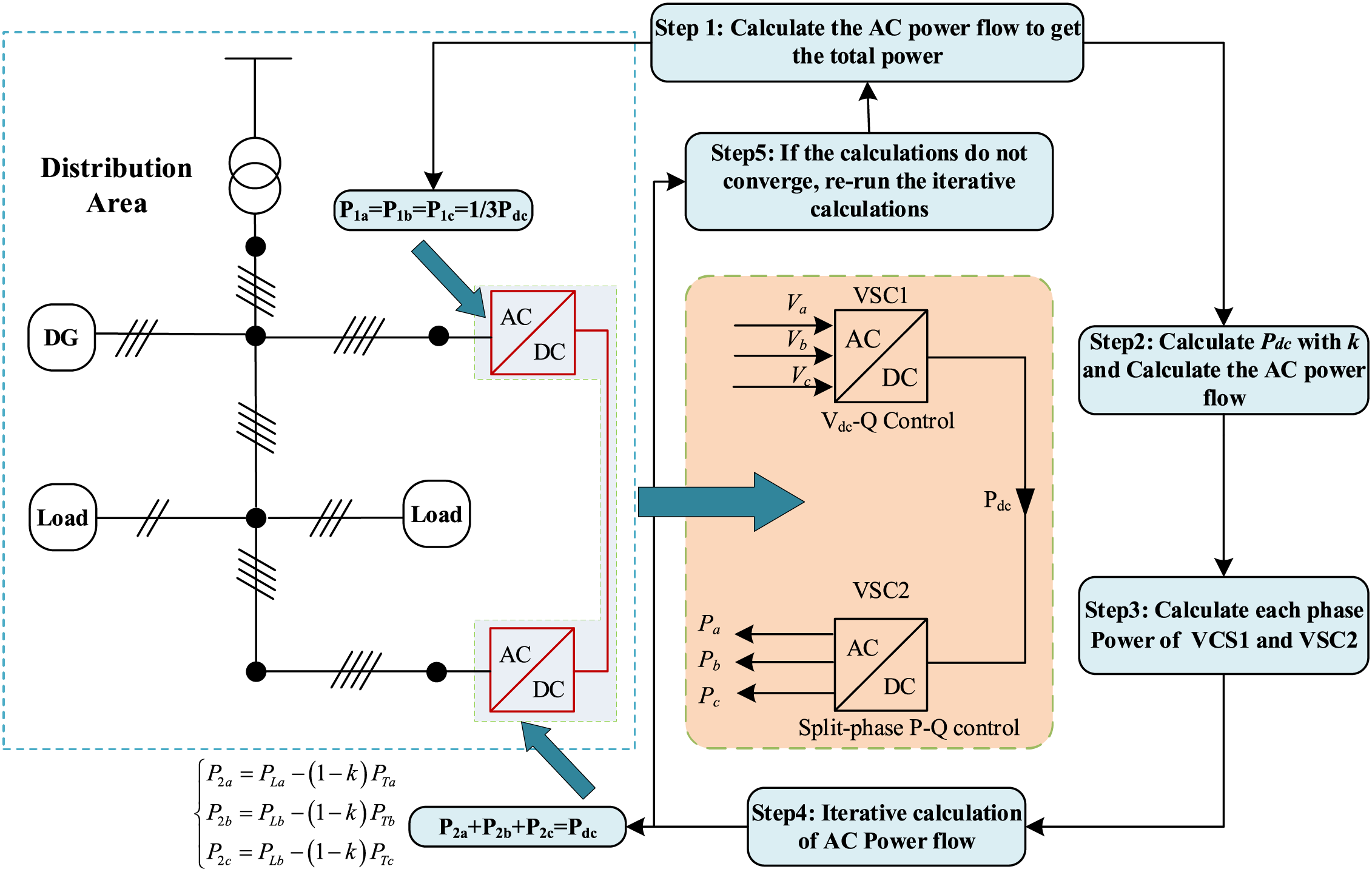
Figure 2: The calculation diagram for EDC-LVDA under unbalanced compensation conditions
Step 1: Initialize and calculate the AC power flow to get the total power and load conditions.
Step 2: Calculate Pdc with Eq. (3) and recalculate the AC power flow with the updated AC power [18].
Step 3: Calculate each phase power of the VSC1 and VSC2 with Eqs. (2) and (4).
Step 4: Iterative calculation of AC power flow.
Step 5: If the calculations do not converge, re-run the iterative calculations.
Based on the above calculation diagram, the iterative AC/DC compensation process in the EDC-LVDA can be plotted in Fig. 3, and the detailed descriptions can be obtained as follows.
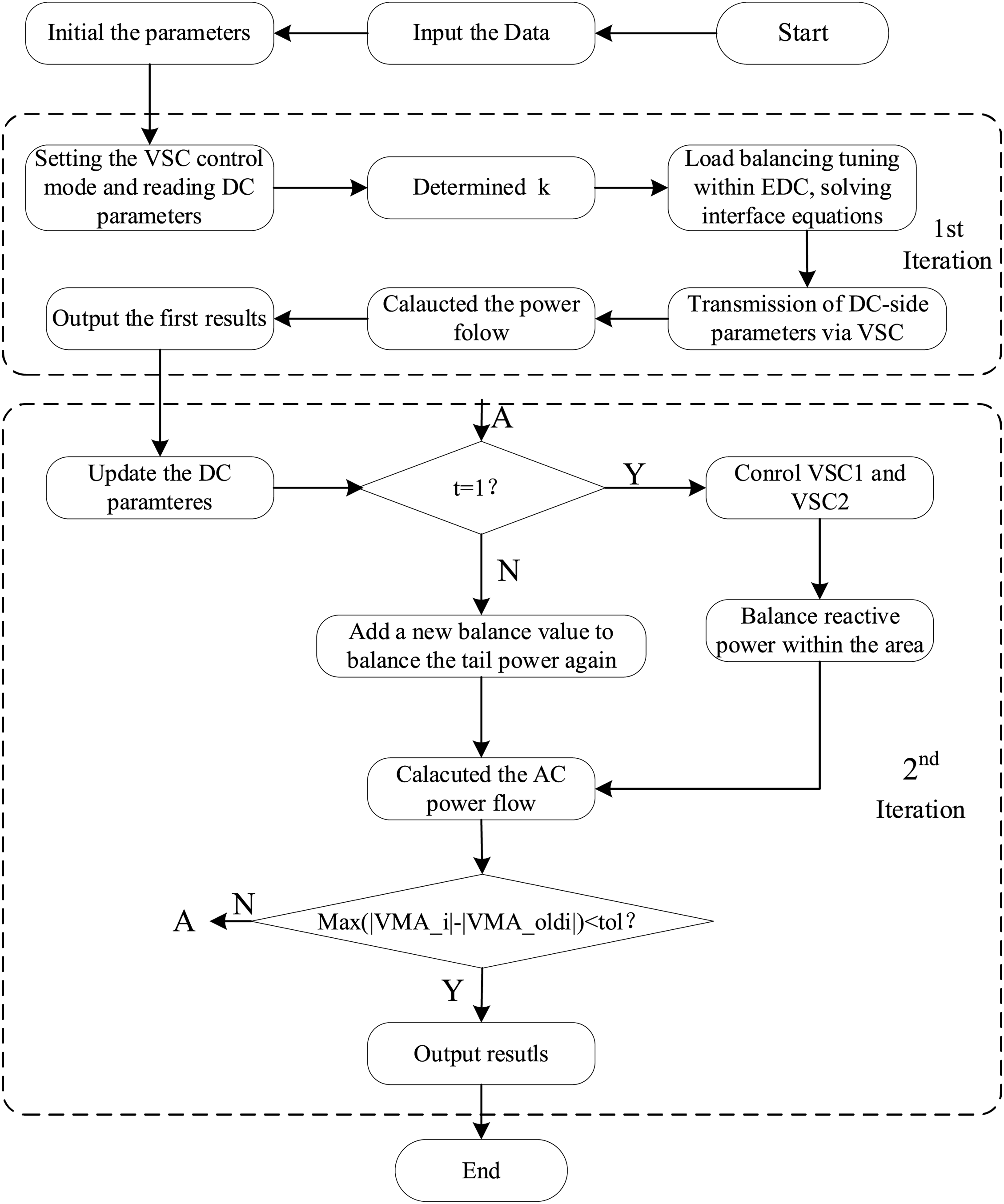
Figure 3: The iterative compensation power process for AC-DC in an EDC-LVDA system
(1) Set the initial values for each substation area and input the raw data.
(2) First iteration: Determine the power transfer coefficient k and the parameters at the EDC. Set the control mode of the upstream VSC to dc-bus, while the downstream VSC is set to split-phase active and reactive power control. Use the following equation to balance the loads within the distribution area.
(3) Second iteration: During the first calculation of the AC-DC power flow, balance the loads within the substation area using three-phase averages.
(4) Perform the second AC-DC iteration. If the three phases within the substation area are still unbalanced, introduce new active and reactive power balancing measures and inject power from the tail end to achieve balance.
(5) Record the iterative values of the AC-DC power flow and compare the differences with the previous iteration to determine whether convergence has occurred.
4 Optimization Operation for EDC-LVDA under Unbalanced Compensation Conditions
Due to the different PV and load conditions at different times, the optimal k for the minimal power loss and voltage qualities is different. And the main point of the proposed optimum operation is to dynamically regulate the k under different load and PV conditions to achieve the minimum power loss and high-quality voltages. The optimal operation consists of two parts: the optimization model and the optimization solving algorithm. Among them, the optimization model includes two components: the objective function and the constraints. The details of each part are introduced as follows.
The objective of optimization is to achieve a comprehensive optimization of voltage quality and system losses while ensuring full compensation of three-phase imbalances. Thus, the objective function can be represented as a weighted sum of the distribution network losses and voltage quality as follows.
where f1 and f2 represent the objective function values for the distribution network loss and voltage quality, respectively. S1 and S2 are the reference values for f1 and f2, which are based on the values of f1 and f2 when the distribution area has not inserted an EDC part.
4.1.1 Objective Function of Power Loss f1 in EDC-LVDA
The power loss f1 in the EDC-LVDA system consists of the VSC converter loss
The loss of each part can be obtained as
where the symbol Z denotes the branch number connecting nodes i and j. Iz,ϕ,t and
4.1.2 Objective Function of Power Quality f2 in EDC-LVDA
The power quality for each node can be indicated by the voltage deviation. Thus, f2 is specified by the voltage ui of phase i at the first end of the station and can be expressed as:
where ue is the rated voltage.
4.2.1 Operation Power Constraint of VSC
The processed power of VSC must satisfy the following equations as
where QVSC and PVSC are the processed active and reactive power of the VSC, respectively. And the SVSC is the power capacity of the VSC.
4.2.2 Power Balance Constraint of the Nodes
The balance constraints of active power and reactive power at node i must satisfy the following equation as
where Pin,i,t and Qin,int are the injected active and reactive power of the node i at time t, respectively.
4.2.3 Current Constraints of the Branches
At time t, the current Iz,t flowing through branch z needs to satisfy.
where Iz,max is the maximum value of the current in branch z.
4.2.4 Operation Constraints of the DC System
The power balance of the DC nodes can be expressed as
where
The DC voltage at all the time and nodes must be between the allowable range, which can be expressed as
where
Similarly, the current limitation of each branch can be expressed as
where
4.2.5 Power Constraints of the PV Nodes
The output power of the PV system must satisfy the following equations as
where
In this paper, a two-layer solving algorithm based on the improved Particle Swarm Optimization (IPSO) algorithm is used for model solving. The upper layer is the power flow model, and the lower layer is the IPSO optimization model. IPSO gradually approaches the optimal solution based on the flying experience of the swarm and the learning process of individuals, achieving optimization of the problem, and is widely applied in the field of power system optimization scheduling [19–21]. The detailed steps of IPSO are shown in Fig. 4, the details operation steps can be obtained as follows:
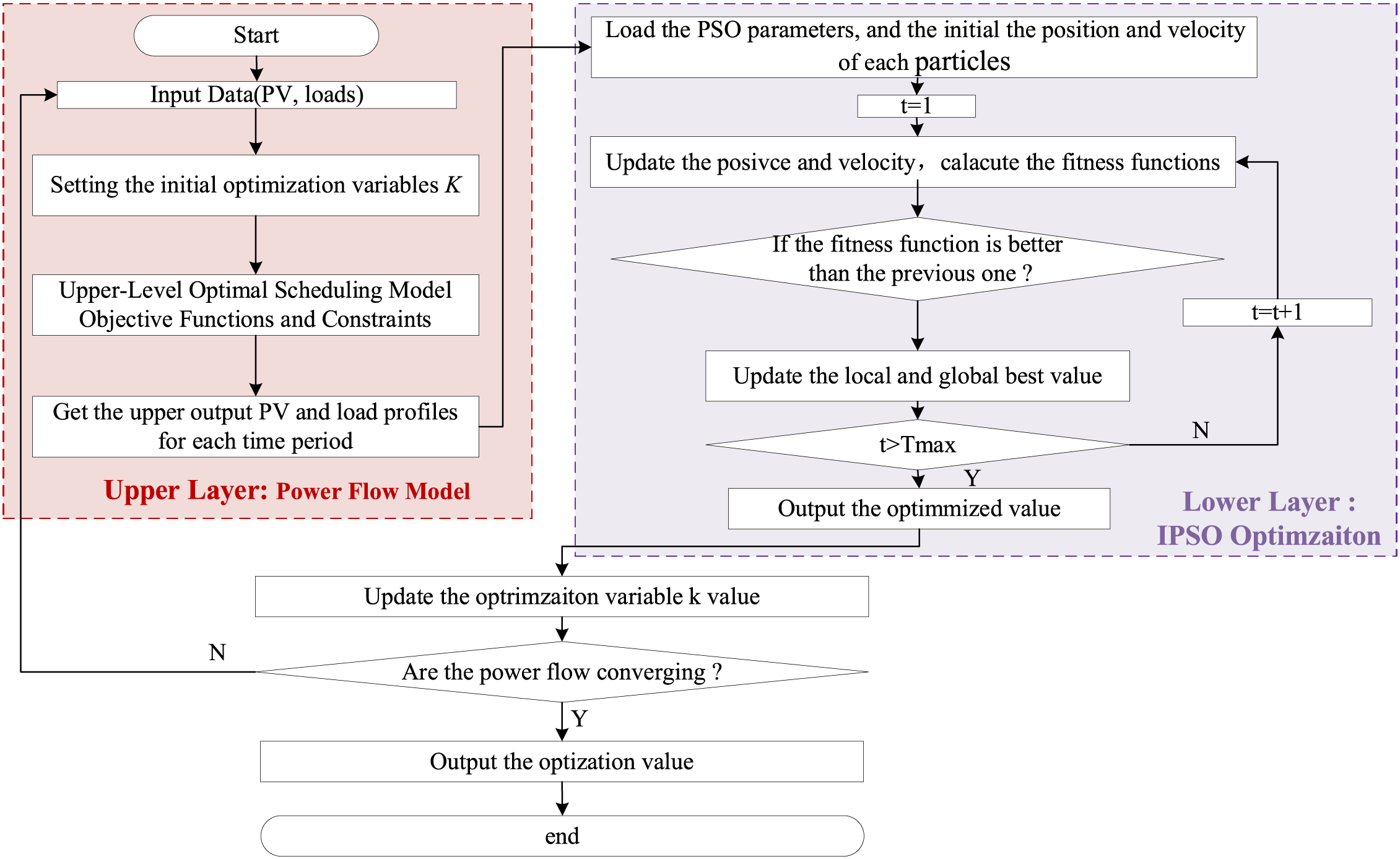
Figure 4: Two-layer solving algorithm process based on the PSO method
Step 1: Solve the upper model. Define decision variables, such as the power factor transferred between substations and the transfer relationships within the substations.
Step 2: Input data such as photovoltaic output and load to calculate the initial values for power flow.
Step 3: Solve the lower-level optimization. Initialize the particle swarm, where each particle represents a potential solution. The initial positions are random but constrained by the feasible region of the decision variables.
Step 4: Set the IPSO parameters, such as inertia weight and individual learning factors.
Step 5: Update using velocity and position updating formulas and calculate the fitness function value.
Step 6: Perform iterative searching, evaluate the objective function value at the new position, and update individual and global best positions.
Step 7: Determine whether the power flow has converged. If not, repeat the cycle. If converged, output the optimization results.
To verify the effectiveness of the proposed optimization scheduling method, an IEEE 13-node network-based EDC-LVDA case study is built and tested. The topology of the EDC-LVDA is shown in Fig. 5, in which a DC is embedded between the first and last nodes of the AC system, and the capacity of the DC interconnection converter is 500 kVA. The resistance of the embedded DC line is 0.015 (per unit value, same below), and the converter parameters are R = 0.001 and X = 0.002. The maximum absolute value of the iterative convergence error is set to be less than ε (1 × 10⁻⁹). VSC1 uses DC-bus voltage control, while VSC2 employs split-phase active and reactive power control. The photovoltaic inverter has a capacity of 20 kVA, and the maximum output of the single-phase photovoltaic system is 10 kW. The output power curves of the photovoltaic nodes at different times are shown in Fig. 6. Table 1 summarizes the connected rated power under different nodes, and the load utilization factor of each node at various times is shown in Fig. 7.
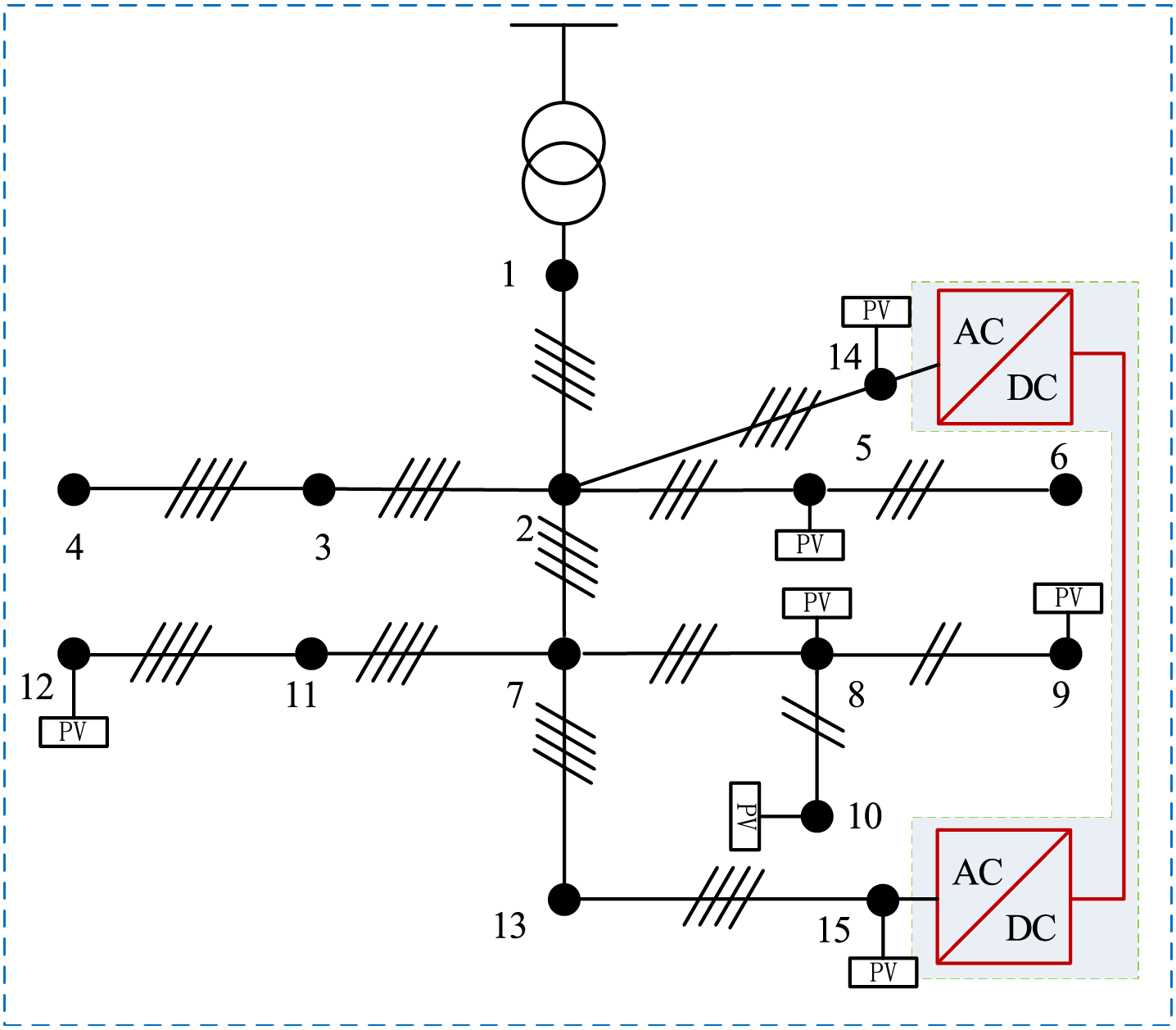
Figure 5: The topology of the IEEE 13-node network based EDC-LVDA case study
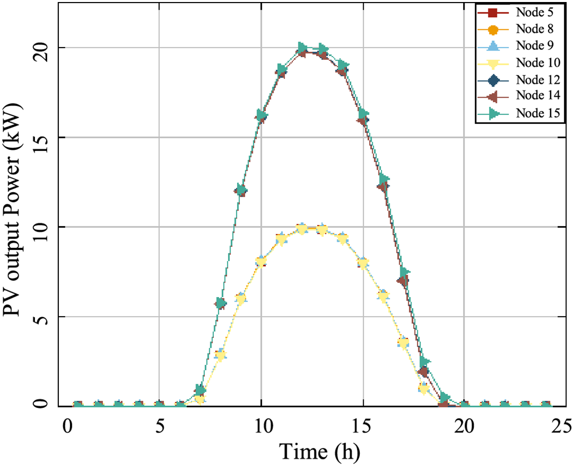
Figure 6: Output power of each PV node
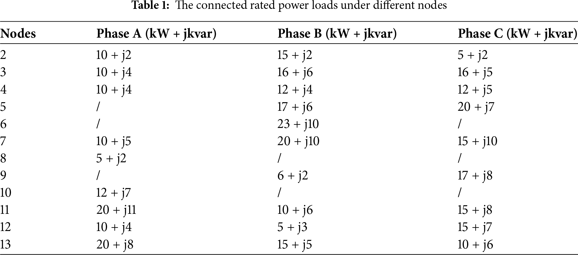
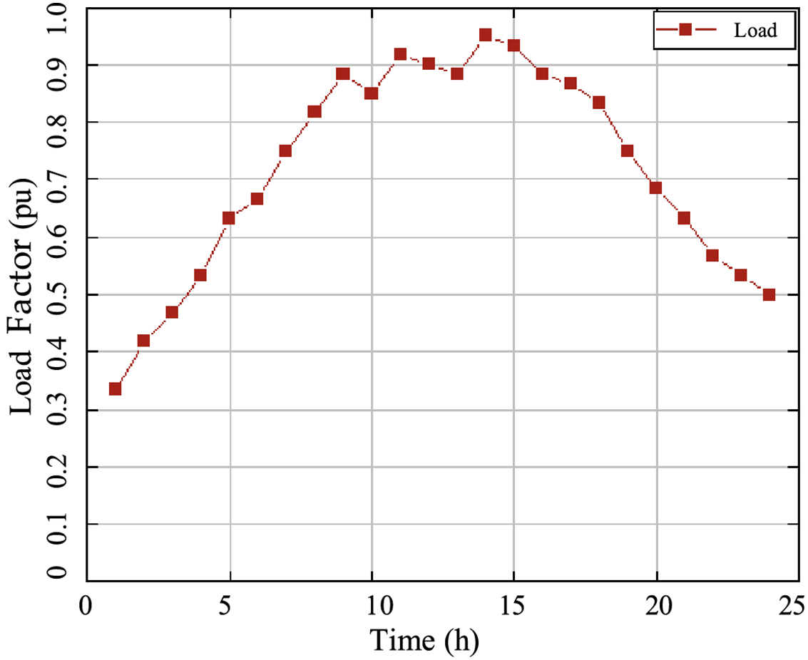
Figure 7: The load utilization factor at different times
Fig. 8 shows the convergence curves of power flow and the optimization method. Fig. 8a shows the convergence curves of maximum absolute difference
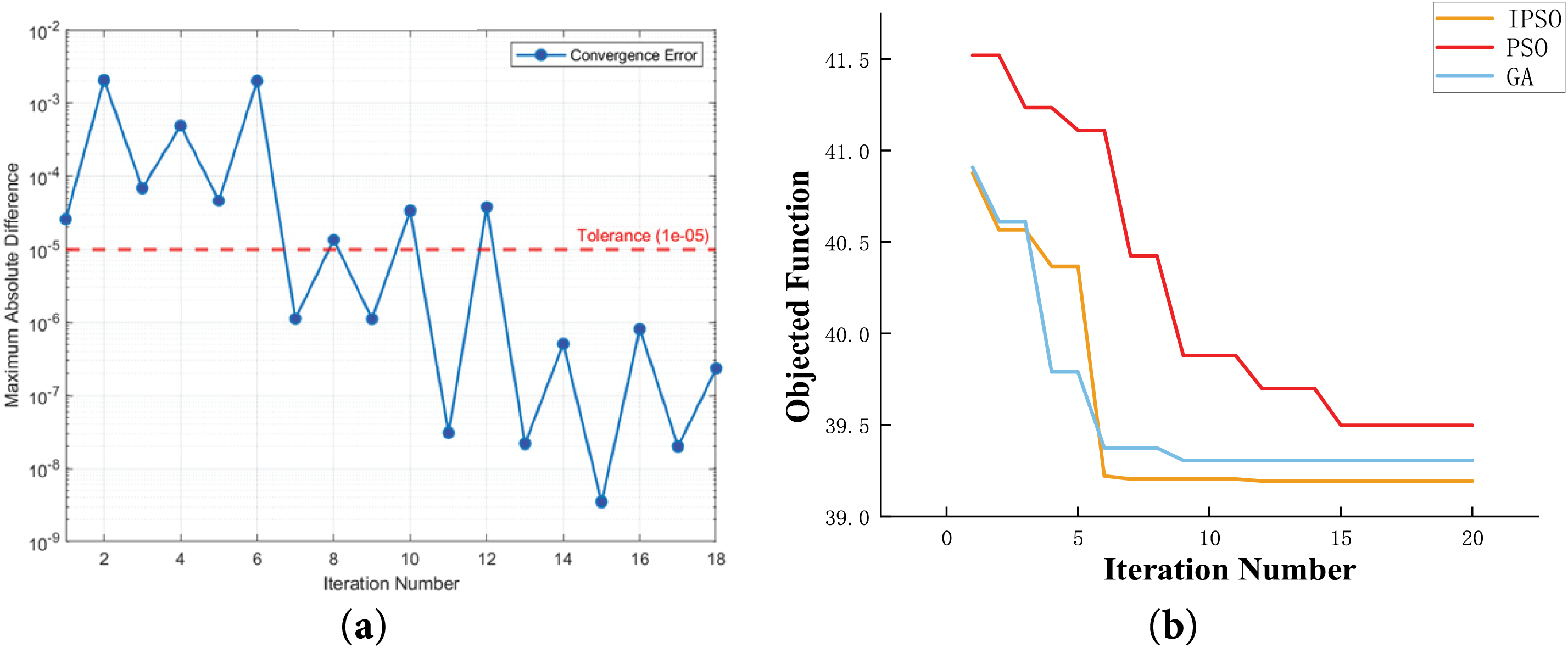
Figure 8: Convergence curves of power flow and optimization method. (a) Power Plow Calculation process; (b) optimization process under different algorithms
The optimal power distribution ratio k during an entire day has been obtained using the proposed optimization scheduling algorithm, as shown in Fig. 9. The corresponding total system loss is depicted in Fig. 10. It can be observed that compared to a fixed power distribution ratio, the proposed method can dynamically calculate the optimal power distribution ratio k, obtaining a significantly lower network loss, with a total loss reduction of 13.8% in a day.
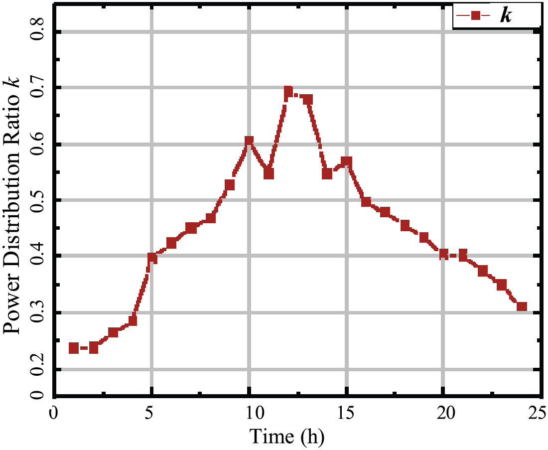
Figure 9: The optimized power distribution ratio
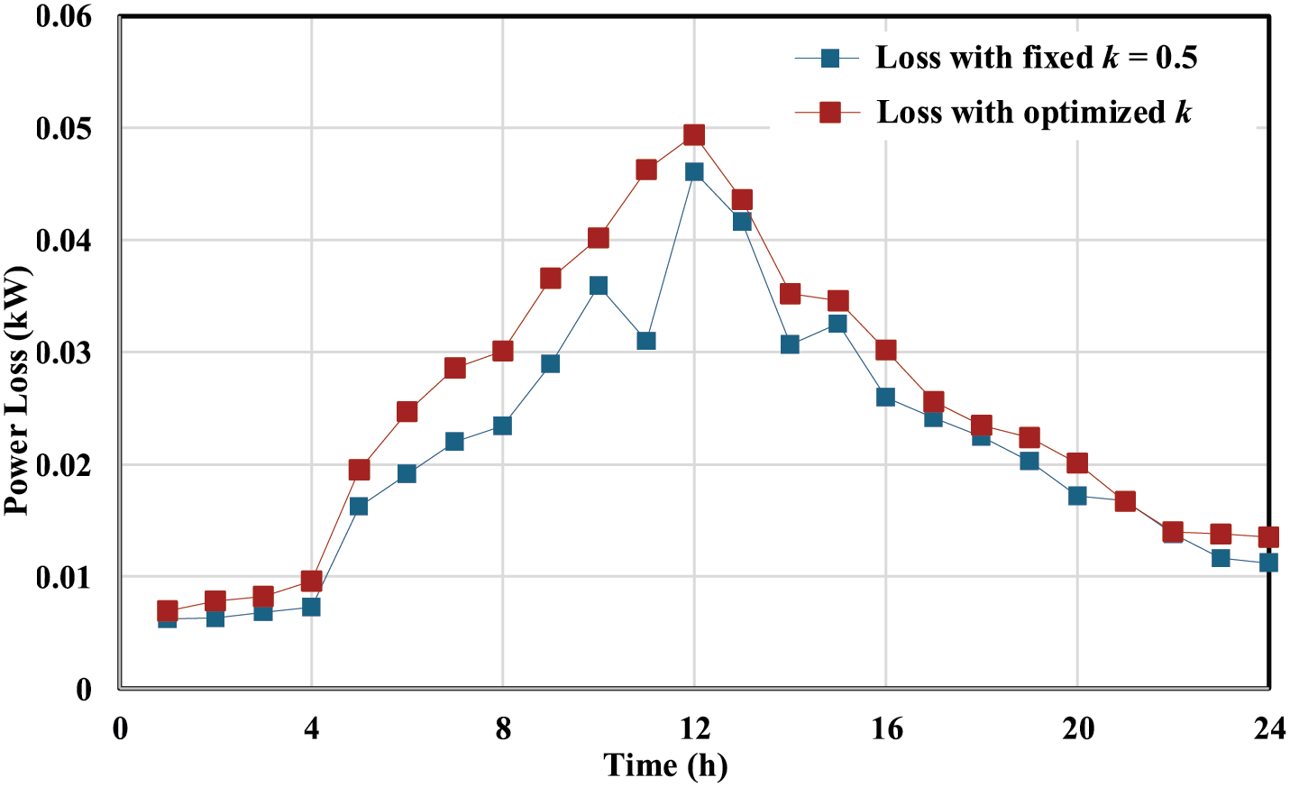
Figure 10: Power loss comparison
Fig. 11 shows the active and reactive power data of each phase at the transformer of the distribution area under the optimal power distribution ratio k. With the proposed optimization scheduling method, the power of each phase can maintain a three-phase power balance despite fluctuations in load and photovoltaic power. This sufficiently demonstrates that the proposed EDC-LVDA scheduling strategy can achieve balanced load distribution in the distribution area even under unbalanced load conditions.
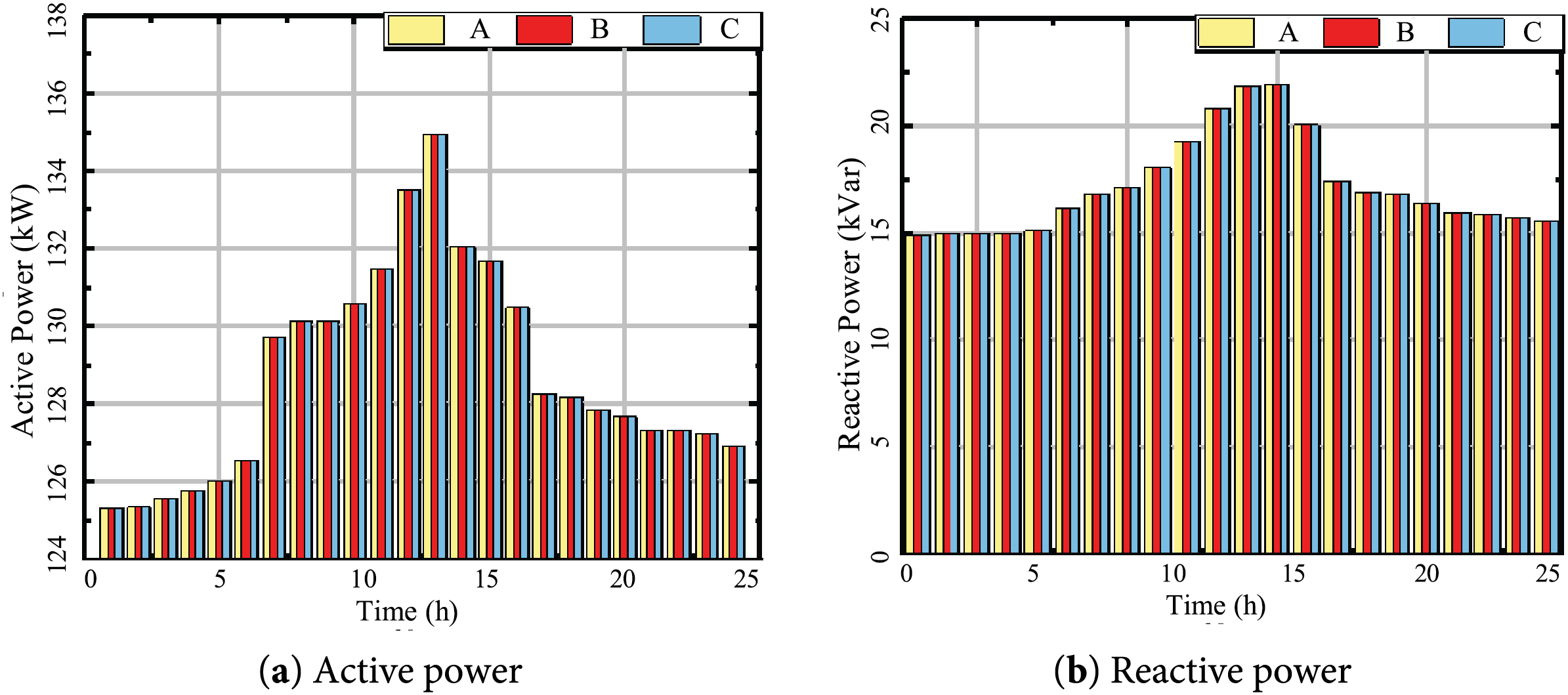
Figure 11: The active and reactive power data of each phase at the transformer and the times
Fig. 12 shows the voltage conditions of each node in the distribution area for each phase. The voltages at all nodes remain within the acceptable standard range of [0.95, 1.05], indicating that the proposed method can effectively address the low voltage issues in the distribution area and ensure the voltage quality of the system.
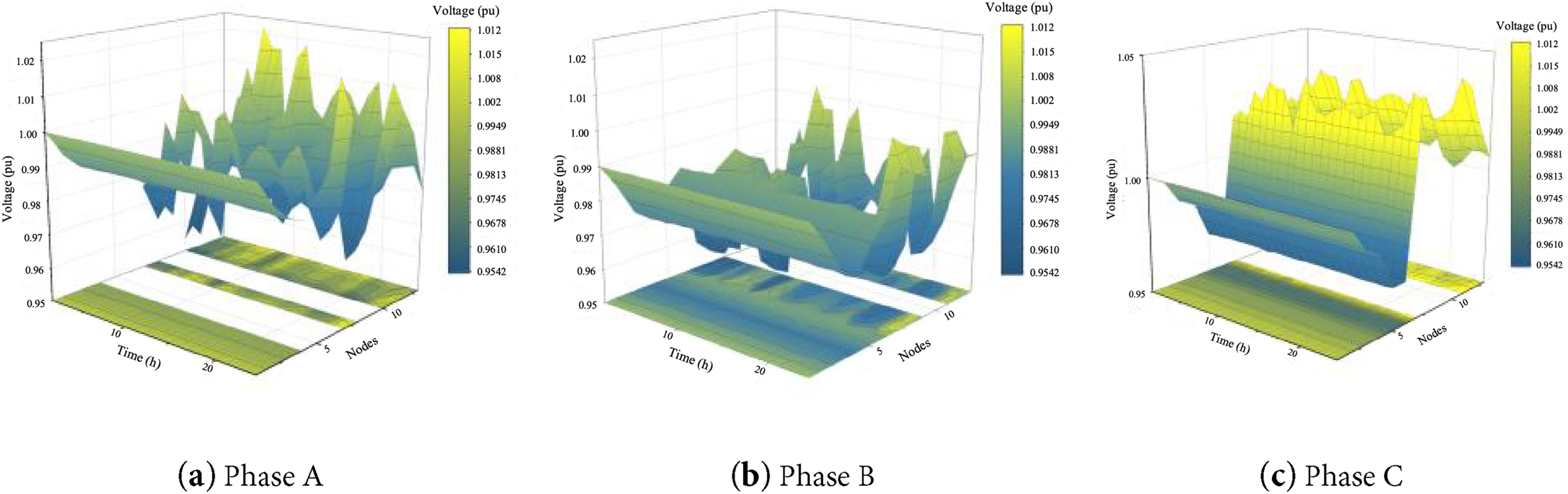
Figure 12: The voltage conditions of each node in the distribution area for each phase
Aiming to address the challenge of power optimization scheduling within an EDC-LVDA, this paper proposes an optimization scheduling strategy for interlinked flexible distribution networks that takes into account three-phase unbalance compensation. Firstly, a power flow calculation method for low-voltage flexible distribution areas that considers three-phase unbalance compensation is proposed. This method can effectively describe the power distribution characteristics under both AC and DC power allocation. Secondly, an optimization scheduling model for flexible low-voltage distribution areas has been constructed, which accounts for network losses, voltage quality, losses in the DC section, and three-phase imbalance. This model can adaptively select the power distribution coefficients for the DC and AC sections under different operating conditions, achieving embedded economic optimization while ensuring compensation for unbalanced conditions. Finally, a case study based on the IEEE 13 bus system is established to validate the proposed method. The results indicate that the proposed method can achieve 100% voltage compliance rate and a 13.8% reduction in network losses, which can support the integration of distributed energy, adapt to new loads such as electric vehicles, strengthen grid resilience, and provide a practical solution for the modernization of low-voltage power grids.
Besides, the proposed approach is designed for the optimal operation of EDC interconnections within a single area. While its current version does not apply to EDC interconnections between different areas, the extension of this approach to cross-area EDC interconnection scenarios will be elaborated in our future publications.
Acknowledgement: None.
Funding Statement: This work was supported by the key technology project of China Southern Power Grid Corporation (GZKJXM20220041), and partly by the National Key Research and Development Plan (2022YFE0205300).
Author Contributions: The authors confirm contribution to the paper as follows: Conceptualization, Zhukui Tan; methodology and software, Dacheng Zhou and Song Deng; data curation, Jikai Li and Zhuang Wu; writing—original draft preparation, Dacheng Zhou; writing—review and editing, Qihui Feng; supervision, Xuan Zhang and Zhukui Tan. All authors reviewed the results and approved the final version of the manuscript.
Availability of Data and Materials: The original contributions presented in the study are included in the article; further inquiries can be directed to the corresponding author.
Ethics Approval: Not applicable.
Conflicts of Interest: The authors declare no conflicts of interest to report regarding the present study.
References
1. Wei YM, Chen K, Kang JN, Chen W, Wang XY, Zhang X. Policy and management of carbon peaking and carbon neutrality: a literature review. Engineering. 2022;8(7):52–63 doi:10.1016/j.eng.2021.12.018. [Google Scholar] [CrossRef]
2. Zhang M, Long Y, Guo S, Xiao Z, Shi T, Xiang X, et al. Stability boundary characterization and power quality improvement for distribution networks. Energies. 2024;17(24):6215. doi:10.3390/en17246215. [Google Scholar] [CrossRef]
3. Amrani Z, Beladel A, Kouzou A, Rodriguez J, Abdelrahem M. Four-wire three-level NPC shunt active power filter using model predictive control based on the grid-tied PV system for power quality enhancement. Energies. 2024;17(15):3822. doi:10.3390/en17153822. [Google Scholar] [CrossRef]
4. Li G, Li J, Yan K, Bian J. Centralized-distributed scheduling strategy of distribution network based on multi-temporal hierarchical cooperative game. Energy Eng. 2025;122(3):1113–36. doi:10.32604/ee.2025.059558. [Google Scholar] [CrossRef]
5. Guo P, Tian Z, Yuan Z, Qu L, Zhang XY, Zhang XP. Future-proofing city power grids: fid-based efficient interconnection strategies for major load-centred environments. IET Renew Power Gener. 2024;18(15):3003–19. doi:10.1049/rpg2.13027. [Google Scholar] [CrossRef]
6. Mtolo D, Dorrell D, Pillay Carpanen R. Balancing of low-voltage supply network with a smart utility controller leveraging distributed customer energy sources. Energies. 2023;16(23):7707. doi:10.3390/en16237707. [Google Scholar] [CrossRef]
7. Guo X, Gan L, Liu Y, Hu W. Coordinated dispatching of flexible AC/DC distribution areas considering uncertainty of source and load. Electr Power Syst Res. 2023;225(042–011):109805. doi:10.1016/j.epsr.2023.109805. [Google Scholar] [CrossRef]
8. Gao C, Wang C, Chen Y, Qu R, Niu K, Chen W. Novel low-carbon optimal operation method for flexible distribution network based on carbon emission flow. Energy Eng. 2025;122(2):785–803. doi:10.32604/ee.2024.058705. [Google Scholar] [CrossRef]
9. Li P, Ji H, Yu H, Wang C. Flexible distribution networks. Amsterdam, The Netherlands: Elsevier; 2024. p. 3–10. doi:10.1016/B978-0-12-823890-5.00002-7. [Google Scholar] [CrossRef]
10. Tan G, Guo X, Zhao W, Qi L, Sun X. Second harmonic suppression for DC output voltage of three-phase four-leg PWM rectifier under unbalanced grid voltage conditions. IEEE Trans Power Electron. 2025;40(8):11088–106. doi:10.1109/TPEL.2025.3551801. [Google Scholar] [CrossRef]
11. Pereira O, Quirós-Tortós J, Valverde G. Phase rebalancing of distribution circuits dominated by single-phase loads. IEEE Trans Power Syst. 2021;36(6):5333–44. doi:10.1109/TPWRS.2021.3076629. [Google Scholar] [CrossRef]
12. Wang J, Zhou N, Chung CY, Wang Q. Coordinated planning of converter-based DG units and soft open points incorporating active management in unbalanced distribution networks. IEEE Trans Sustain Energy. 2020;11(3):2015–27. doi:10.1109/TSTE.2019.2950168. [Google Scholar] [CrossRef]
13. Zhang B, Tang W, Cong PW, Zhang XH, Lou CW. Multi-time scale optimal control in hybrid AC/DC distribution networks based on SOP and VSC. Adv Technol Electr Eng Energy. 2017;36(9):11–9. (In Chinese). doi:10.1049/joe.2018.8527. [Google Scholar] [CrossRef]
14. Zhang B, Zhang L, Tang W, Li G, Wang C. Optimal planning of hybrid AC/DC low-voltage distribution networks considering DC conversion of three-phase four-wire low-voltage AC systems. J Mod Power Syst Clean Energy. 2024;12(1):141–53. doi:10.35833/mpce.2022.000404. [Google Scholar] [CrossRef]
15. Ge L, Zhang W, Yan F, Yuan XD, Yu YZ. Optimal scheduling of flexible interconnected distribution network based on adaptive model predictive control. Electr Power Autom Equip. 2020;40(6):15–23. (In Chinese). doi:10.16081/j.epae.202005009. [Google Scholar] [CrossRef]
16. Li T, Guo Q, Wang X, Ji H, Tu C, Hou Y, et al. A comprehensive control strategy for three phase unbalance and light and heavy load in flexible interconnected distribution stations based on F-SOP. Power Syst Technol. 2024;48(10):4358–66. (In Chinese). doi:10.13335/j.1000-3673.pst.2023.1268. [Google Scholar] [CrossRef]
17. Feng Q, Li J, Zhou J, Xu Y, He Q, Gao Y. A coordinated power quality improvement control strategy for AC/DC hybrid distribution networks based on three-phase four-leg flexible interconnection converter. Front Energy Res. 2025;13:1602269. doi:10.3389/fenrg.2025.1602269. [Google Scholar] [CrossRef]
18. Bakır H, Guvenc U, Duman S, Kahraman HT. Optimal power flow for hybrid AC/DC electrical networks configured with VSC-MTDC transmission lines and renewable energy sources. IEEE Syst J. 2023;17(3):3938–49. doi:10.1109/JSYST.2023.3248658. [Google Scholar] [CrossRef]
19. Bakır H, Kahraman HT, Yılmaz S, Duman S, Guvenc U. Dynamic switched crowding-based multi-objective particle swarm optimization algorithm for solving multi-objective AC-DC optimal power flow problem. Appl Soft Comput. 2024;166(3):112155. doi:10.1016/j.asoc.2024.112155. [Google Scholar] [CrossRef]
20. Zhu H, Liu T. Rotor displacement self-sensing modeling of six-pole radial hybrid magnetic bearing using improved particle swarm optimization support vector machine. IEEE Trans Power Electron. 2020;35(11):12296–306. doi:10.1109/TPEL.2020.2982746. [Google Scholar] [CrossRef]
21. Belgana S, Fortin-Blanchette H. A novel neural network-based droop control strategy for single-phase power converters. Energies. 2024;17(23):5825. doi:10.3390/en17235825. [Google Scholar] [CrossRef]
Cite This Article
 Copyright © 2026 The Author(s). Published by Tech Science Press.
This work is licensed under a Creative Commons Attribution 4.0 International License , which permits unrestricted use, distribution, and reproduction in any medium, provided the original work is properly cited.
 Downloads
 Citation Tools