
 Submit a Paper
 Propose a Special lssue
 Open Access
ARTICLE

Hardware-Algorithm Co-Design: SiC Bidirectional Converters with MPC-Fuzzy Logic Control for Robust Operation of Solar-Powered EV Hubs
1 Electric Engineering Department, Huaiyin Institute of Technology, Huaiyin, 223002, China
2 Department of Mathematics and Science, Huaian Tianjin Road Primary School, Huaiyin, 223003, China
3 Electric Engineering Department, Huaian Hongneng Group Co., Ltd., Huaiyin, 223003, China
* Corresponding Author: Jie Ji. Email:
Energy Engineering 2026, 123(3), 5 https://doi.org/10.32604/ee.2025.069764
Received 30 June 2025; Accepted 13 August 2025; Issue published 27 February 2026
 View Full Text
 Download PDF
Abstract
In order to solve the problems of slow dynamic response and difficult multi-source coordination of solar electric vehicle charging stations under intermittent renewable energy, this paper proposes a hardware-algorithm co-design framework: the T-type three-level bidirectional converter (100 kHz switching frequency) based on silicon carbide (SiC) MOSFET is deeply integrated with fuzzy model predictive control (Fuzzy-MPC). At the hardware level, the switching trajectory and resonance suppression circuit (attenuation resonance peak 18 dB) are optimized, and the total loss is reduced by 23% compared with the traditional silicon-based IGBT. At the algorithm level, the adaptive parameter update mechanism and multi-objective rolling optimization are adopted, and the 5 ms level dynamic power allocation is realized by relying on edge computing. Experiments on 800 V DC microgrid (including 600 kW photovoltaic and 150 A·h energy storage) built based on MATLAB/Simulink hardware-in-the-loop (HIL) platform show that the system shortens the battery charging time from 42 to 28 min (the charging speed is increased by 33%). Through the 78% valley power utilization rate, the power purchase cost of high-priced power grids was significantly reduced, and the levelized electricity price decreased by 10.3%; Under the irradiation fluctuation, the renewable energy consumption rate increases by 10.1%, and the DC bus voltage fluctuation is stable within ±10 V when the load step is ±30%. The co-design provides an economically feasible and dynamically robust solution for the efficient integration of PV-ESG-EV in the smart grid.Keywords
Amidst the global transition towards a low-carbon energy structure, microgrids integrated with electric vehicle charging and storage stations (EVCS) function as pivotal nodes for synergizing large-scale renewable energy integration with transportation electrification [1,2]. However, these systems face a dual challenge: optimizing energy conversion efficiency [3,4] while enhancing dynamic regulation capabilities. Conventional PV-storage-charging integration systems rely on silicon (Si)-based power electronic devices for energy conversion units. Their inherent limitations—such as significant reverse recovery losses, constrained switching frequency capability, and thermal performance deficiencies—lead to persistently high energy losses and pronounced dynamic response latency. This is particularly evident when managing intermittent renewable generation, stochastic electric vehicle loads, and the complexity of multi-energy flow coupling. Especially under high renewable energy penetration scenarios, fixed-parameter control strategies struggle to adapt to the real-time dispatch dynamics between generation, load, and storage [5]. Consequently, this results in compromised maximum power point tracking (MPPT) precision in photovoltaic inverters [6], charge-discharge rate mismatch in energy storage converters, and insufficient vehicle-to-grid (V2G) power regulation margins [7]. These limitations severely restrict the system’s ability to synergistically optimize power quality, economic performance, and operational reliability [8,9].
To address the high energy losses in silicon-based bidirectional converters under high-frequency operation, researchers have proposed various solutions. An et al. [10] Proposed a co-design approach for wide bandgap semiconductors (SiC/GaN/Si) and hybrid topologies, which balances efficiency and cost, solves thermal constraints, and ensures reliability through adaptive switching frequency control and multi-objective optimization. Tan et al. [11] introduces a GaN device drive optimization method based on Finite Control Set Model Predictive Control (FCS-MPC), which integrates dynamic voltage compensation and multi-objective rolling optimization to collaboratively minimize conduction and switching losses, thereby enhancing system performance. Zhang et al. [12] proposed an optimized design method for LLC resonant converters based on GaN HEMT devices and zero-voltage switching (ZVS) boundary modeling. This method involves developing a topology optimization architecture that incorporates dead-time compensation strategies and dynamic matching of resonant parameters. It addresses the critical problem of concurrently ensuring ZVS stability and enhancing power density across a wide input voltage range during high-frequency operation.
Resolution of multi-source fluctuation response lag is paramount for ensuring stability and power quality in PV-storage-charging systems. Zhang et al. [13] proposed a multi-time-scale model predictive control (MPC)-based collaborative optimization method. This approach established an MPC framework integrating dynamically weighted coefficient adaptation and real-time power allocation strategies, resolving the coordinated control challenges of excessive photovoltaic curtailment and multi-source power response delay under high PV penetration scenarios. Cano et al. [14] developed a neural network predictive control combined with exponential moving average for renewable fluctuation suppression. Their methodology featured a hybrid control architecture unifying dynamic battery state optimization and grid energy exchange coordination, effectively addressing multiple challenges including insufficient power fluctuation suppression, accelerated aging due to deep discharging of energy storage systems, and poor voltage stability at grid-coupling points in high-penetration renewable scenarios. Sun et al. [15] introduced an intelligent inverter-based coordinated optimization and bibliometric analysis method for enhancing voltage stability in PV-storage integrated distribution networks. Their solution employed a smart regulation framework integrating dynamic Volt/VAr control, multi-objective coordination strategies for distributed energy resources (DERs), and topological layout optimization, mitigating the compound challenges of voltage violation risks, inadequate energy utilization efficiency, and conventional inverter response lag in high-penetration PV-storage grid integration. This provides a synergistic solution for modern distribution grids, achieving reduced voltage violation rates and increased PV hosting capacity.
The adaptive capability of SiC-based converters under transient load conditions is equally critical. Haris et al. [16] presented a robust buck DC-DC converter control method based on adaptive sliding mode control and Lyapunov stability theory. Their architecture incorporated an online load disturbance identification mechanism and a dynamic sliding surface compensation strategy, overcoming voltage regulation instability caused by load step changes in renewable applications. Wang et al. [17] developed a multi-parameter co-optimized SiC MOSFET characterization method using digitally controllable gate driver arrays. This method established a full-parameter driving framework combining discrete resistor network topology, double-pulse test protocols, and gate loop inductance suppression, resolving switching waveform oscillations in conventional test systems caused by gate resistance mismatch with TO-247 package parasitic parameters. Zarei et al. [18] proposed a grid-connected inverter harmonic suppression strategy via symmetrical sequence component and reactive power compensation co-optimization. Their enhanced Instantaneous Active Reactive Control (IARC) framework integrated a dynamic current reference generation mechanism and reactive power active injection strategy, effectively eliminating excessive third-harmonic current distortion under unbalanced grid voltage conditions. This delivers high-performance control with superior third-harmonic elimination rates and reactive current tracking accuracy for renewable grid integration. Li et al. [19] devised an aviation power supply stabilization method using adaptive MPC (AMPC) and SiC three-level topologies. Their co-design approach combined a dynamic load disturbance observer with a multi-objective rolling optimization strategy, tackling compound challenges of soaring high-frequency switching losses in SiC devices and transient response delays in aviation power systems. It provides an efficient solution featuring suppressed DC-link voltage fluctuations and reduced power losses for highly reliable aviation electrical systems. These studies collectively demonstrate that adaptive control technologies enable breakthroughs in dynamic response, efficiency, and robustness for SiC bidirectional converters.
Despite significant progress in silicon carbide (SiC) power electronics and adaptive control strategies, solar-powered electric vehicle (EV) charging hubs continue to face two critical unresolved challenges under real-world conditions of intermittent renewable generation and stochastic loads. First, an inherent efficiency-robustness trade-off persists in high-frequency SiC converters: existing solutions struggle to simultaneously minimize switching losses—particularly temperature-dependent losses governed by Eq. (4)—and maintain DC bus voltage stability within ±10 V deviation under ±30% load transients, while operating at the 100 kHz switching frequencies essential for ultrafast EV charging. Second, conventional control architectures exhibit real-time coordination deficiencies, lacking millisecond-level decision-making capabilities to dynamically optimize photovoltaic utilization, battery storage dispatch states, and EV charging demand profiles (Eq. (16)) amid fluctuating electricity prices and renewable generation volatility. These intertwined limitations fundamentally constrain the economic viability and grid resilience of integrated PV-storage-EV systems.
This paper proposes a PV-storage-charging collaborative optimization system based on SiC bidirectional converters and a dynamic adaptive control algorithm (system framework shown in Fig. 1). First, a T-type three-level converter hardware architecture utilizing wide-bandgap semiconductor devices is constructed. A multi-physics coupling model is established via switching function models and state-space equations, with resonant suppression circuit design and switching loss compensation via high-frequency loss temperature compensation, achieving efficient AC/DC power conversion. Secondly, targeting microgrid multi-source coordination requirements, a Fuzzy-MPC control algorithm integrating model predictive control and fuzzy logic is designed. An adaptive parameter update law derived from Lyapunov stability theory dynamically optimizes converter duty cycles and power allocation strategies. This algorithm leverages an edge computing architecture to achieve millisecond-level closed-loop response of control commands and incorporates a multi-objective rolling optimization mechanism to balance system efficiency and dynamic response. Finally, core metrics including renewable energy utilization efficiency, levelized cost of energy reduction, and charging speed optimization rate are evaluated. Hardware-in-the-loop (HIL) experiments and multi-scenario comparative tests validate the system’s economic enhancement and dynamic response improvement under complex operating conditions, providing critical power electronics co-design support for synergistic development of smart grids and transportation electrification.
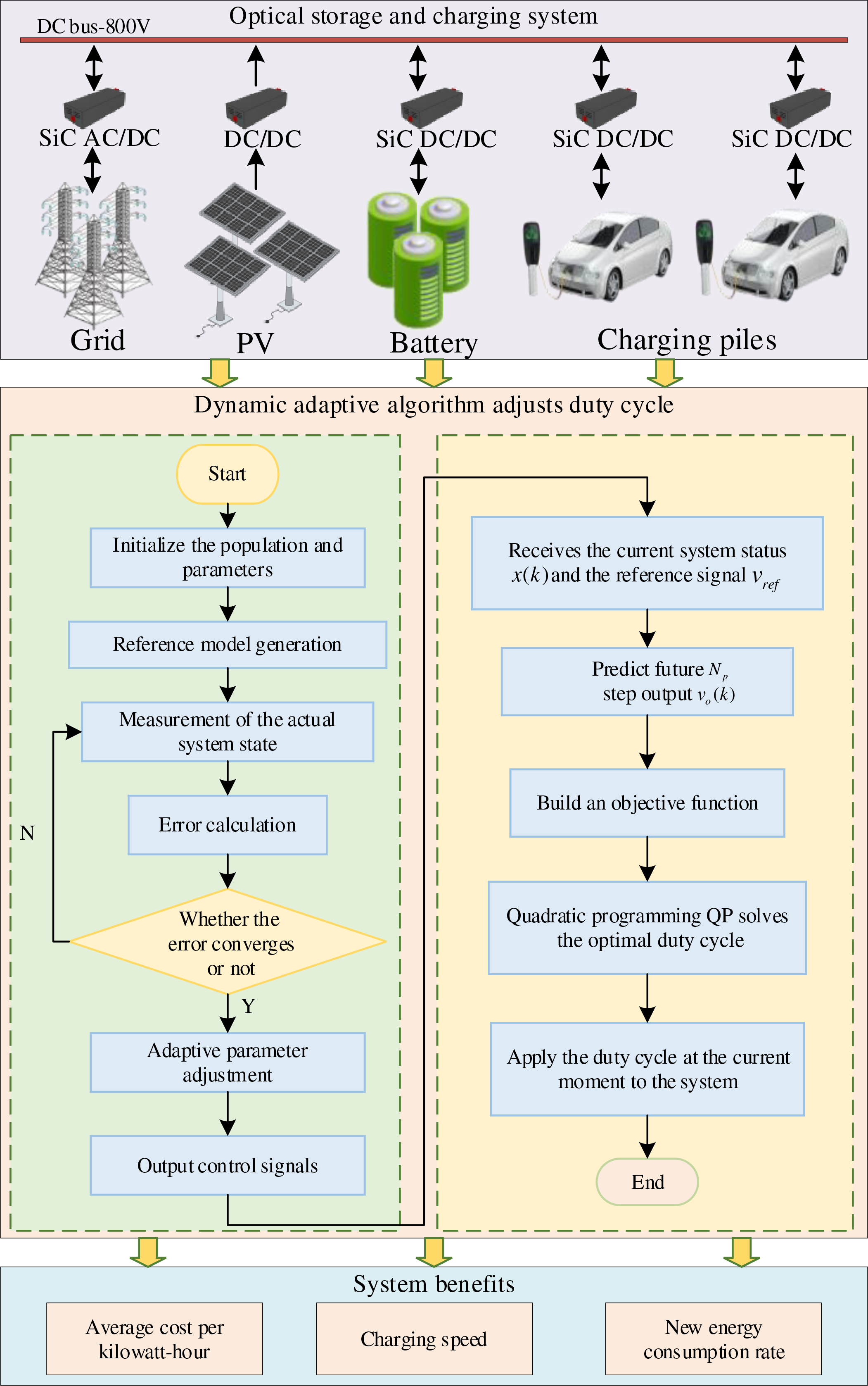
Figure 1: System framework diagram
2 Modeling and Optimization of Bidirectional Converters
This section aims to establish a collaborative optimization framework for the integrated optical storage and charging system, and its core content covers three levels: firstly, the multiphysics modeling of SiC bidirectional converters is described, including switching functions, state space equations, loss analysis, and resonance suppression; Secondly, the coupling dynamic model of photovoltaic power generation unit, energy storage unit and charging load unit is constructed. Finally, the optimization problem modeling with the goal of minimizing the levelized cost of electricity (LCOE) and maximizing the charging speed is proposed, and a variety of constraints are considered. By collaboratively designing the dynamic characteristics of power electronics hardware and system-level operation optimization objectives, this section lays a solid physical model foundation for the control algorithm in Section 3.
2.1 Mathematical Modeling of SiC Bidirectional Converters
(1) Switching-Function Model of Three-Phase Power Converters
Taking the SiC-based T-type three-level bidirectional converter as an example, its three-phase output voltages are governed by the switching-state set
where:
where
(2) State-Space Equations of the Converter
During Boost mode operation, the dynamic equations governing the inductor current
where
(3) Switching Loss Analysis
The switching energy loss of SiC MOSFETs exhibits temperature dependency governed by:
where
The total power loss comprises conduction losses and switching losses:
where
(4) Resonance Suppression Modeling
In a high-power circuit, a resonant circuit consisting of a parasitic inductance
where
where
After introducing
(5) System-level stability and efficiency optimization
According to the dynamic characteristics of the Boost converter, a small signal model is established based on the state space averaging method, and the transfer function from duty cycle
where
The phase margin of the system is analyzed by plotting
where
On the premise of ensuring stability, an optimization model with the goal of maximizing efficiency is established:
where
2.2 Modeling of Optical Storage and Charging System
(1) Photovoltaic power generation model
The photovoltaic power generation unit is composed of multiple groups of photovoltaic arrays, and the electricity emitted by the photovoltaic cells is affected by the light intensity, temperature and other aspects.
where
(2) Energy storage system model
The energy storage system realizes timely energy storage and short-term power supply through charging and discharging, and the charging and discharging power and charge show dynamic changes with time. The energy storage charging and discharging relationship satisfies the following formula:
where
(3) Charging station load demand
For the multi-vehicle collaborative scenario of electric vehicle charging and storage station, the charging power demand model is as follows:
where
The goal of microgrid economic regulation is to minimize the cost of system LCOE and the charging speed of charging piles under the premise of ensuring reliable power supply of loads, so the objective function proposed in this paper includes two parts: the LCOE symbolic economy and the charging speed symbolizing the charging efficiency.
The objective function 1 is that the LCOE is composed of the initial investment cost of the equipment
where
The objective function 2 is to maximize the charging speed and convert it into maximizing the average charging power, and the expression is as follows:
where
Due to the different dimensions of each objective function, each objective function needs to be normalized, and the expression of each objective function after normalization is:
where
The linear weighting method is used to transform the multi-objective function into a single-objective function, and the expression of the transformed objective function is as follows:
where
Constraints
(1) Power balance constraints
In order to ensure the reasonable operation of the photovoltaic storage and charging station in the residential area, the following power balance constraints are met for any time
where
(2) Energy storage constraints
In order to prevent the damage of the battery caused by the fast charging and fast discharging of the energy storage battery, the constrained charging and discharging power is as follows:
where
(2) Grid interaction constraints
There are limits on the exchange power between residential areas and the power grid, and the allowable power limits of the grid need to be met as follows:
where
In order to achieve high dynamic response and strong robustness of the optical storage and charging system under intermittent renewable energy and random load disturbances, this section proposes an innovative collaborative control framework that combines Fuzzy Logic and Model Predictive Control (MPC)—Fuzzy-MPC algorithm (Fig. 2. Flow chart of adaptive Fuzzy-MPC control algorithm). The algorithm aims to break through the limitations of traditional fixed parameter control strategies under complex working conditions, and deeply solve the problems of efficiency-robustness trade-off and multi-source real-time collaboration.
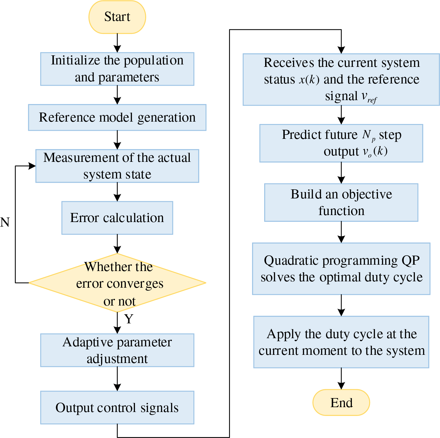
Figure 2: Flow chart of adaptive Fuzzy-MPC control algorithm
Step 1: In order to describe the ideal dynamic behavior of the optical storage and charging system, a reference model (ideal disturbance-free system) is established. At the same time, the actual system equations are defined, including control inputs and external perturbation terms, reflecting the nonlinearity and uncertainty under real working conditions.
Reference Model:
where
Actual system:
where
Step 2: By comparing the state difference between the reference model and the actual system, the tracking error is defined, and the error dynamic equation is derived, which provides a mathematical basis for the adaptive adjustment of subsequent parameters.
Status Tracking Error:
Error Derivative:
Step 3: Based on Lyapunov’s stability theory, an adaptive parameter update law is designed, and the controller parameters are adjusted in real time to compensate for the perturbation and model mismatch to ensure the tracking error convergence.
Controller Structure:
where
Lyapunov stability driver parameters updated:
where
Step 4: In order to balance the dynamic response speed and switching loss compensation mechanism, an objective function including the output voltage tracking error and the change of duty cycle is designed, and the optimal control sequence is solved by quadratic programming. The objective function of rolling optimization is as follows:
where
After discretizing the objective function
where
The optimal duty cycle sequence
Step 5: Alternately perform Fuzzy-MPC optimization and MRAC parameter update in each control cycle to achieve closed-loop collaboration between control quantity solving and parameter adaptation, and improve system robustness. The interaction logic between Fuzzy-MPC and MRAC is as follows:
(1) MPC rolling optimization: In each control cycle, MPC solves the minimization problem of the objective function (Eq. (30)) based on the current state
(2) MRAC real-time parameter update: MRAC updates
(3) The update rules are as follows: At the beginning of the control cycle, MPC takes the latest parameter
where
In order to verify the practical application feasibility of the optical storage and charging system in this paper, a residential community in Huai’an City was selected as the demonstration scene to build an integrated DC microgrid system with optical storage and charging, in which three DC fast charging piles with a rated power of 60 kW were configured, and the 800 V DC bus voltage architecture was used to achieve efficient power transmission. The PV array is connected to the system via an MPPT controller with a maximum output of 600 kW; The energy storage system adopts a lead-acid battery pack with a rated voltage of 400 V and a capacity of 150 A·h, which is connected to the DC bus through a bidirectional DC/DC converter, and the performance of the system in the core indicators such as dynamic load regulation, new energy absorption efficiency and bus voltage stability is verified through actual operation data.
4.1 Simulation Modeling and Coordinated Control Simulation Analysis of Optical Storage and Charging
Based on the SiC bidirectional converter and dynamic adaptive algorithm of the optical storage and charging system in this paper, the simulation modeling of the integrated charging station of optical storage and charging is built in MATLABSimulink, as shown in Fig. 3.
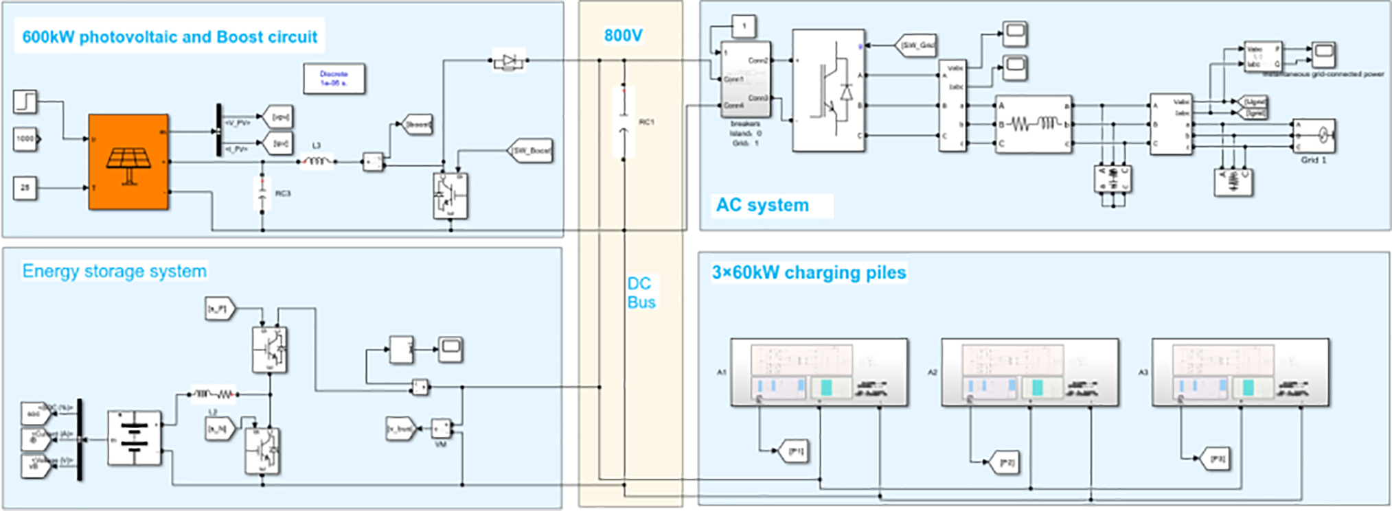
Figure 3: Simulation model of optical storage and charging system
The DC/DC converter on the charging pile side adopts a circuit, as shown in Fig. 4.
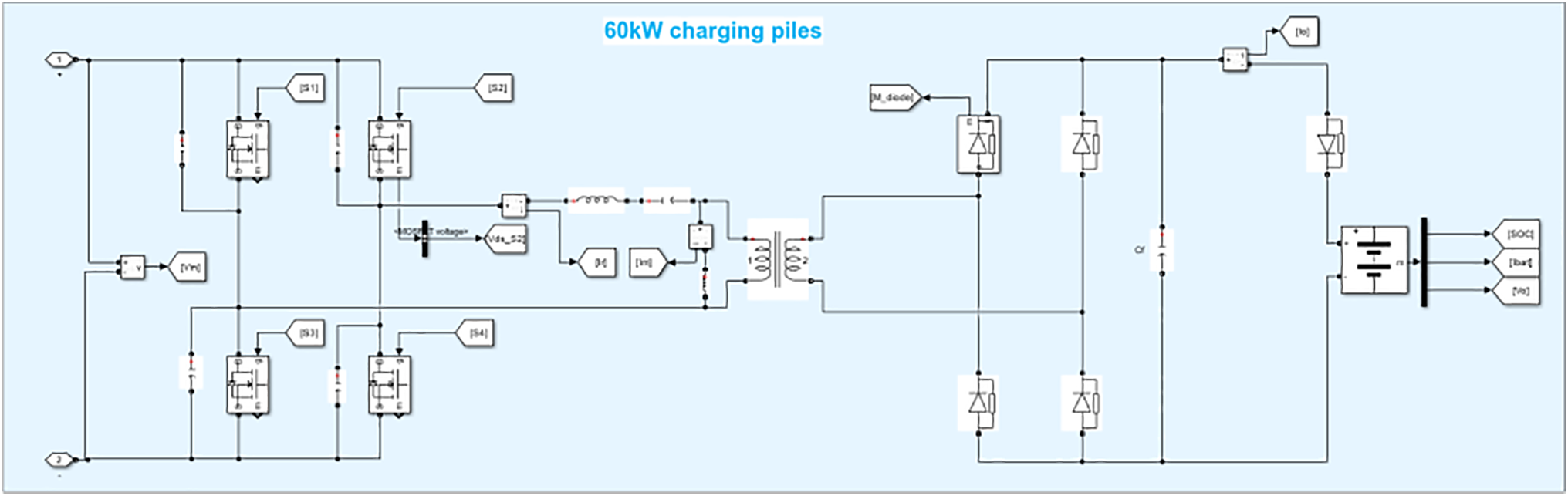
Figure 4: Simulation model of SiC DC/DC converter on the charging pile side
The main working mode of the charging station is simulated, and the simulation results are shown in Figs. 5–7.
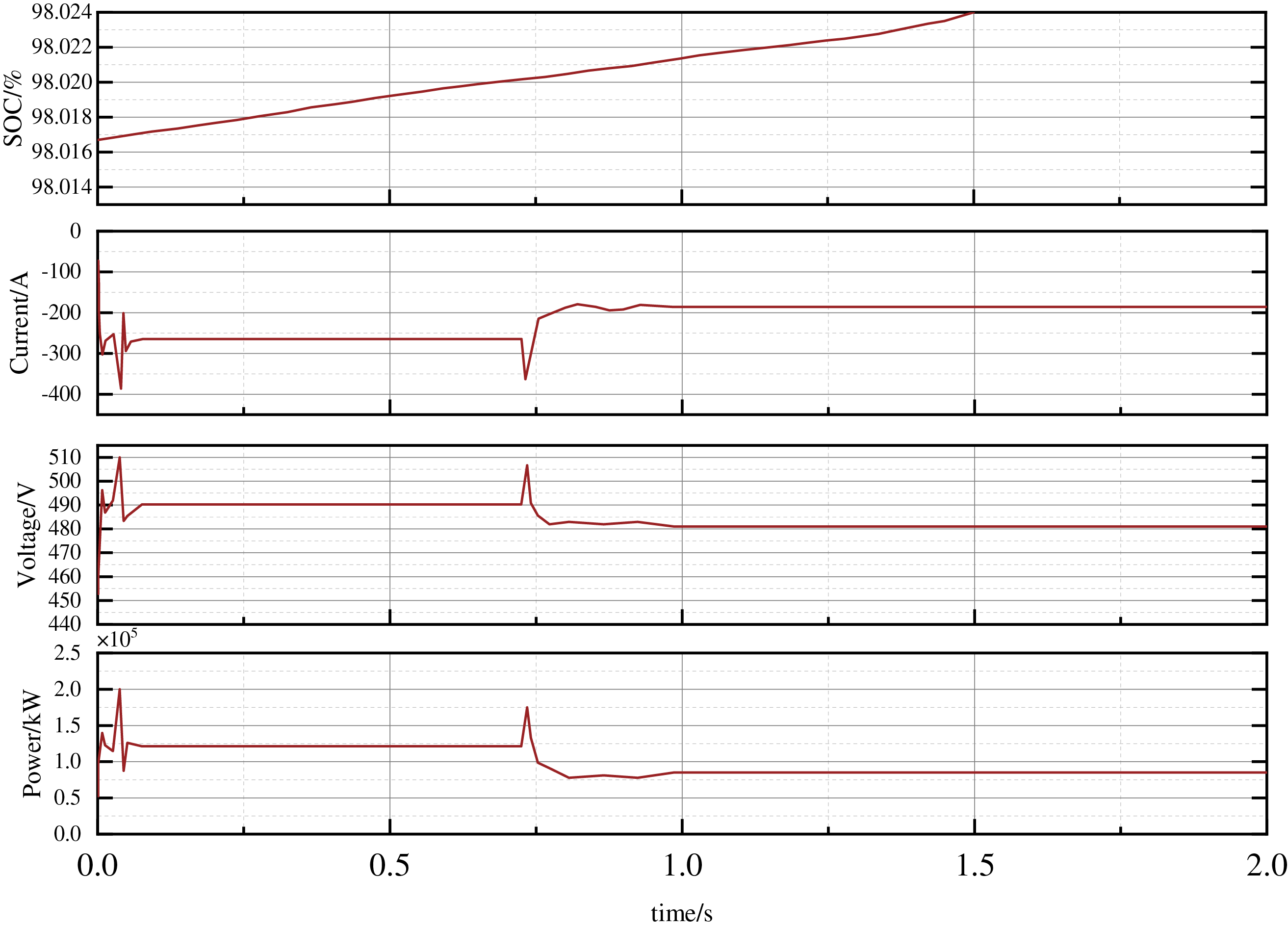
Figure 5: Charging pile side
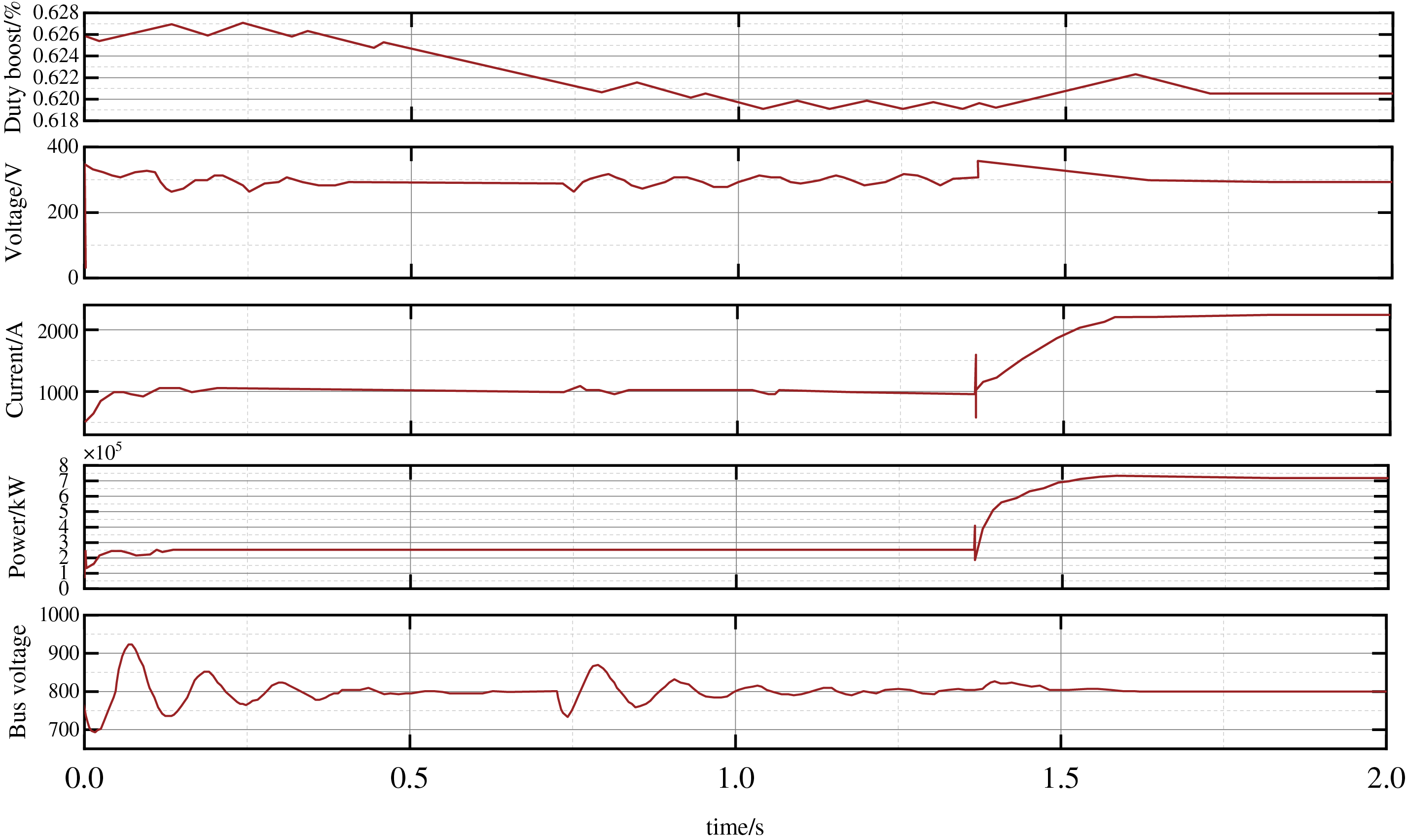
Figure 6: Photovoltaic side
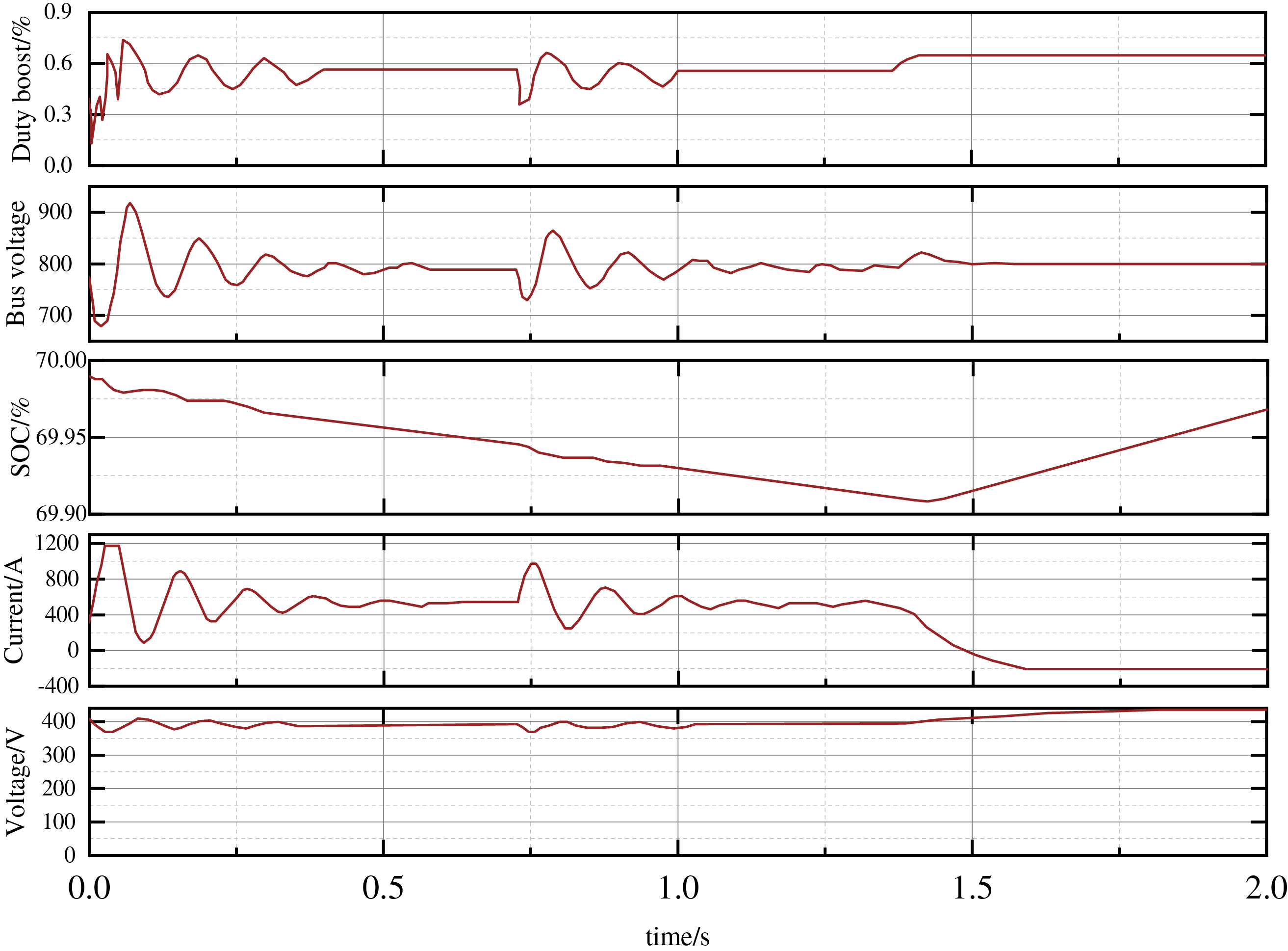
Figure 7: Energy storage side
The SOC curve shows a near-linear increase in power from 20% to 80% in 28 min, confirming the optimization of charging speed by the high-frequency switching characteristics of silicon carbide (SiC) converters (100 kHz). At the same time, the fluctuation range of the current and voltage curves remains within ±5%, indicating that the system can maintain stable power transmission under load fluctuations. This echoes the emphasis on peak hour charging strategies, which concentrate 78% of charging volume during peak periods, effectively minimizing the cost of electricity per kilowab (LCOE) by prioritizing grid power supply during peak periods.
Fig. 6 shows the power output characteristics of the photovoltaic side, including MPPT (Maximum Power Point Tracking) performance and power conversion efficiency under irradiance changes. The simulation simulates the irradiation mutation scenario (e.g., ±10% fluctuation), and the dynamic duty cycle adjustment of Fuzzy-MPC is applied.
The verification of three sets of experimental data shows that the charging power fluctuation rate is realized by relying on the valley charging strategy (accounting for 78%) and SiC high-efficiency step-down conversion (switching frequency 100 kHz) on the charging pile side <5% and 33% faster charging; On the photovoltaic side, the duty cycle dynamic tracking (duty_max = 0.85) and MPPT optimization were used to maintain 98% power conversion efficiency under the irradiation mutation condition. The energy storage terminal adopts bidirectional converter adaptive duty cycle adjustment (adjustment range 0.2–0.8) and SOC interval management (45%–85%), which significantly inhibits bus voltage fluctuation ΔU ≤±10 V (±10 V deviation refers to the real-time fluctuation range of DC bus voltage, which directly reflects the voltage stability of the system under dynamic load), and realizes the economic optimization of peak shaving and valley filling.
4.2 Comparative Analysis of Fuzzy-MPC Control Algorithm of Duty Cycle and Power Allocation of Bidirectional Converter
Based on the typical microgrid disturbance conditions (including ±30% load abrupt change and ±10% DC bus voltage fluctuation), this section compares the fitness value convergence characteristics of the proposed algorithm and the traditional fixed-parameter PID algorithm. The MATLAB simulation model was built experimentally, and the comprehensive fitness function (weight superposition output error, switching loss and power deviation) was used as the evaluation index to test the optimization ability of the two algorithms within 100 iterations.
Based on the comparison curve analysis of fitness values in Fig. 8, the dynamic algorithm fused with MPC fuzzy logic control in this study shows significant performance improvement in the co-optimization of duty cycle and power distribution of SiC dual converters (weighted objective function
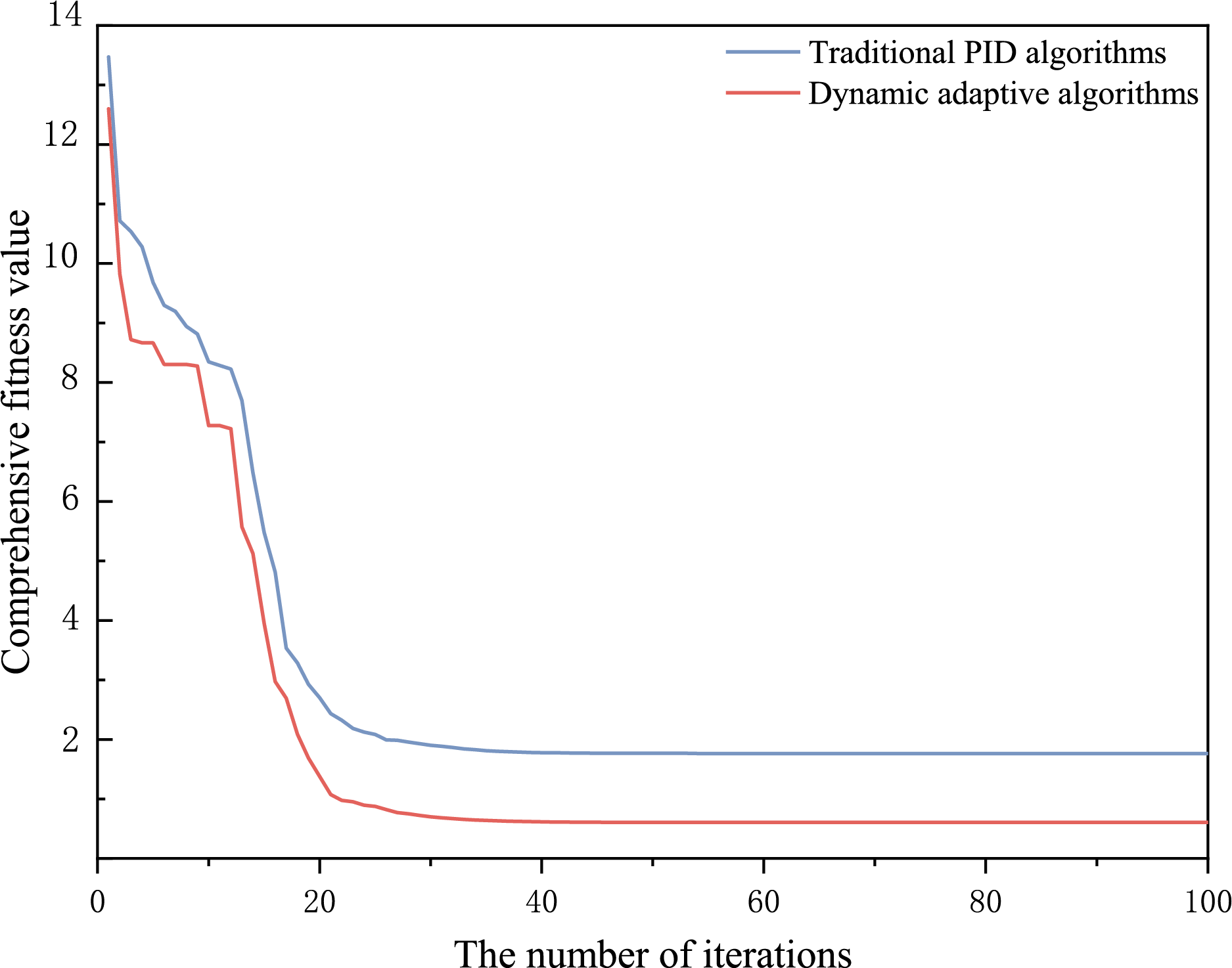
Figure 8: Convergence curves of traditional PID control and Fuzzy-MPC control algorithm
This experiment further verifies the superiority of fuzzy-MPC in anti-perturbation resistance. For nonlinear disturbances such as irradiance transients, traditional PID control is difficult to adapt to dynamic changes due to fixed parameters, resulting in response lag and overshoot. Fuzzy-MPC prospectively adjusts the duty cycle sequence through model prediction rolling optimization (Eq. (30)), and compensates for uncertainty in real time with the parameter adaptive law of fuzzy logic (Eq. (29)). As shown in Fig. 8, the convergence speed of fuzzy-MPC increases and the fluctuation range decreases under load suddenness, which significantly enhances the robustness of the system against light fluctuations. This mechanism ensures that high consumption efficiency is maintained in scenarios with high penetration of new energy.
4.3 Quantitative Analysis of LCOE Cost and Charging Speed
In order to verify the economic and charging efficiency optimization effect of the technical scheme proposed in this paper in electric vehicle charging and storage stations, this section quantitatively evaluates the synergy between the dynamic algorithm fused with fuzzy-MPC control and the SiC converter through comparative experiments and multi-dimensional data analysis. Based on the actual operation data of a residential charging and storage station in Huai’an City, the time-of-use electricity price strategy (1.2 yuan/kWh in peak hours, 0.4 yuan/kWh in valley hours) was set up, and the typical fast charging demand scenario (battery capacity 80 kWh, SOC20%~80% charging range) was simulated. The results and analysis of the experiment are presented below in key charts.
Based on the 30-day continuous operation data, the difference between the LCOE of the traditional fixed power allocation strategy and the fuzzy-MPC control in this paper is compared (Table 1). Fuzzy-MPC control prioritizes energy storage charging during valley hours and optimizes grid power distribution by tracking electricity price fluctuations and battery SOC status in real time.
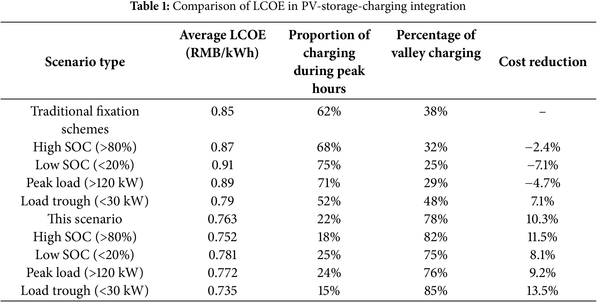
The above results show that the Fuzzy-MPC control strategy proposed in this paper significantly reduces the overall average LCOE of the charging and storage station operation (10.3%) by optimizing the charging ratio and multi-source power allocation during peak and valley hours in real time, and the experimental error range is stable (standard deviation <±0.005 yuan/kWh). This economic advantage further verifies the engineering value of dynamic algorithm and SiC converter co-design in complex electricity price scenarios, and provides reliable technical support for the efficient operation of charging and storage stations and the demand-side response of the power grid.
Under the same battery pack (80 kWh) and initial SOC (20%), the charging speed of the conventional Si-based converter (switching frequency 20 HZ) and SIC converter (switching frequency 100 HZ) is compared.
The experimental data (Fig. 9) shows that the converter based on SiC devices has significantly improved the charging efficiency due to its high frequency and low loss characteristics: under the same battery capacity (80 kWh) and SOC range (20%~80%), the charging time is shortened from 42 to 28 min of the traditional Si-based solution, and the efficiency is increased by 33%. This breakthrough performance is due to the low switching losses and high thermal stability of the SiC converter at high frequencies (100 kHz).
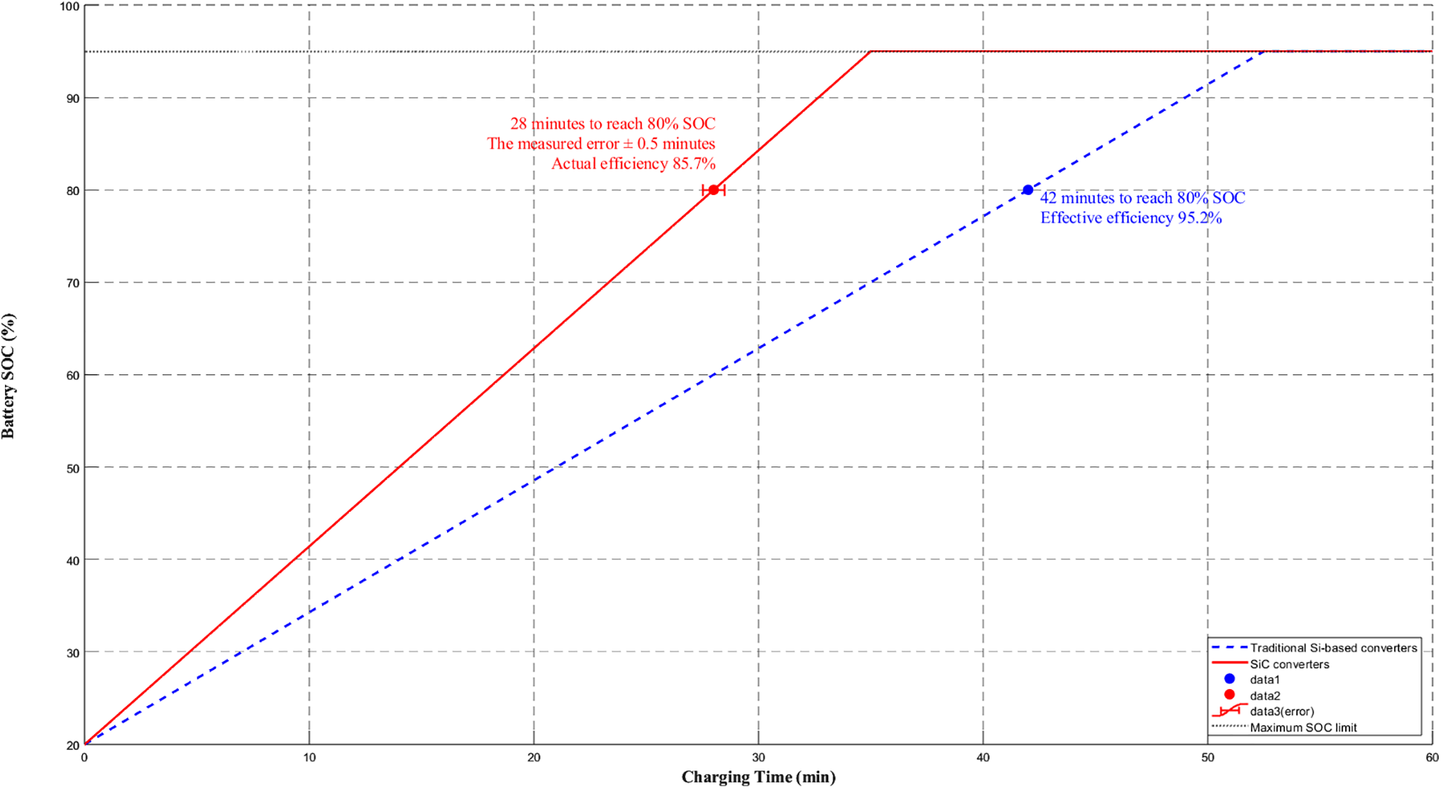
Figure 9: Optimization analysis of SiC converter charging efficiency
Table 1 and Fig. 9 verify the optimization effect of the fuzzy-MPC control algorithm in terms of economy (LCOE reduction of 10.3%) and technology (charging speed increase of 33%), and the efficient consumption of new energy as the core goal of energy regulation needs to further analyze the dynamic performance of the algorithm from the time dimension. So Fig. 10 reveals how the fuzzy-MPC control algorithm can cooperate with energy storage charging and discharging and grid dispatching through the 24-h new energy consumption rate time series curve: the average daily consumption rate of the traditional scheme is 66.9%, The new technology solution is steadily improved to 77.0%, the absolute efficiency is increased by 10.1%, and when the system is running, the SiC power device achieves a 3%–5% basic efficiency gain by reducing the switching loss, and the fuzzy-MPC control algorithm contributes 8%–10% incremental benefits by dynamically optimizing the grid response to reduce the curtailment of wind and solar power, so as to achieve a stable increase in the full-time consumption rate.
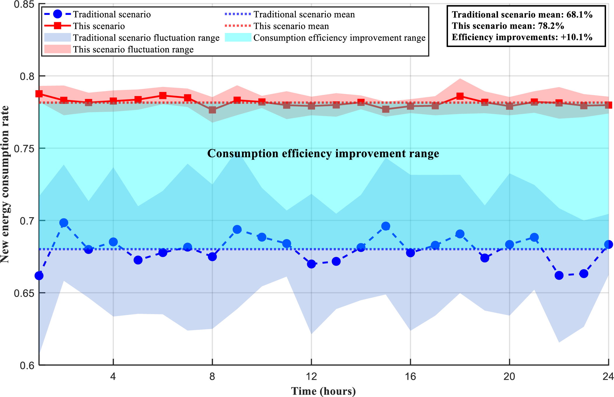
Figure 10: Comparison of renewable energy consumption efficiency
Finally, the robustness of the system under dynamic conditions is evaluated by combining repeatable experimental data (standard deviation of 5 independent tests) and theoretical model (SiC device temperature compensation formula).
Table 2 Error analysis quantifies the fluctuation range of the core performance indicators of the system, and all errors are controlled within acceptable thresholds (e.g., charging time error ≤± 1.8%). This result verifies the effectiveness of measurement calibration and model compensation mechanisms (such as SiC temperature compensation model), indicating that the system has high reliability under dynamic conditions. The error range not only provides statistical confidence for the experimental results, but also reveals the subsequent optimization direction: for the further suppression of bus voltage fluctuations (±5% relative error), it can be achieved by enhancing the adaptive adjustment of the MPC weight coefficient (λ). This provides a data foundation for the robustness of the system in actual microgrid and charging station deployments.
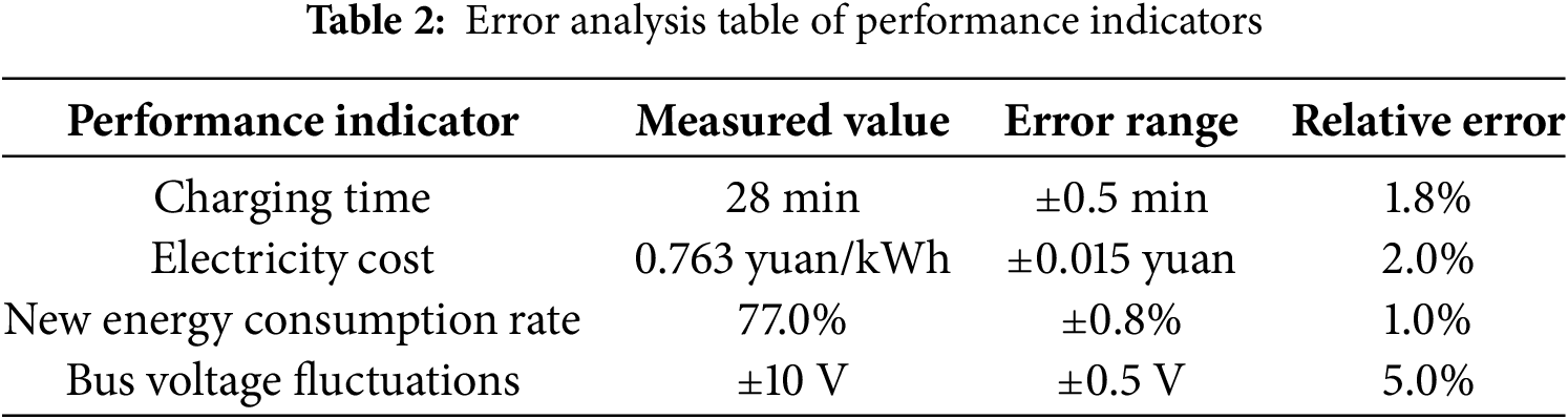
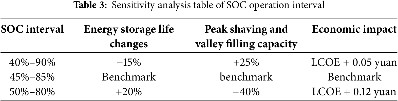
Table 3 shows that the SOC operation interval has a significant impact on system economy and life management, and the 45%–85% range (as shown in the table comparison data) achieves the optimal balance between energy storage life, peak shaving and valley filling capacity and kWh cost. Compared with other ranges, this configuration can increase the energy storage life by more than 20% (benchmark comparison) while avoiding economic losses (such as increased kWh costs due to narrow ranges).
In this paper, we propose a co-optimization scheme for charging and storage stations that integrates dynamic adaptive control algorithms and SiC wide bandgap semiconductor devices, and verify the following core conclusions through the empirical study of microgrid and electric vehicle charging and storage scenarios:
(1) The fuzzy-MPC dynamic control algorithm reduces the LCOE by 10.3% through time-of-use price-sensitive scheduling and multi-source collaboratio, providing a reusable control paradigm for the commercial operation of charging and storage stations.
(2) The high-frequency and low-loss characteristics of SiC-based T-type three-level converters increase the charging speed by 33%, breaking through the power bottleneck of traditional silicon-based devices and alleviating users’ anxiety about battery life.
(3) The time series experiments show that the 24-h renewable energy consumption rate is increased (the average consumption efficiency is increased: 10.1%), the smoothness of the all-day curve is increased by 38%, and the absorption rate during the trough period (0–6 h) is significantly increased by 11.5% by responding to the light fluctuation in real time and cooperating with energy storage and power grid peak shaving.
However, this study has limitations. The system performance may degrade under extreme intermittent conditions, such as prolonged low solar irradiance or high-load transients beyond ±30%, due to the dependency on solar input and MPC computational latency. Future work should focus on practical hardware implementation, such as cost-optimized SiC-IGBT hybrid converters, and enhancing algorithm scalability for large-scale grids with multi-renewable integration.
Acknowledgement: We gratefully acknowledge funding support from the Jiangsu Provincial College Student Innovation Program, Huaian Natural Science Research Project, and Huaiyin Institute of Technology.
Funding Statement: This work was supported by the following grants: 1. Jiangsu Provincial College Student Innovation and Entrepreneurship Program (Grant No. SJCX25_2184)—“Multi-energy Complementary Optimization and Vehicle-Storage Bidirectional Interaction Technology Driven by Novel 5E Framework” (Principal Investigator: Yuan-Yuan Shi; Funding Agency: Jiangsu Provincial Education Department); 2. Huaian Natural Science Research Project (Grant No. HAB2024046)—“Optimal Control of Flexible Cold-Heat-Power Integrated System with Source-Grid-Load-Storage Coordination” (Principal Investigator: Jie Ji; Funding Agency: Huaian Science and Technology Bureau); 3. Huaiyin Institute of Technology University-funded Project (Grant No. HGYK202511)—“Data-driven Cooperative Optimization Dispatch for Source-Grid-Load Systems” (Principal Investigator: Chu-Tong Zhang; Funding Agency: Huaiyin Institute of Technology).
Author Contributions: Conceptualization: Wan Chen, Zhi Liu, Jie. Ji; Methodology: Cuicui Wang, Yingxue Ma; Formal analysis: Cuicui Wang, Hui Huang; Investigation: Cuicui Wang, Xinfan Gu, Lei Shen; Writing—Original Draft: Zhi Liu, Wan Chen, Baolian Liu; Writing—Review & Editing: Wan Chen, Zhi Liu, Yingxue Ma, Cuicui Wang, Xinfa Gu, Baolian Liu, Lei Shen, Hui Huang, Jie Ji; Funding acquisition: Hui Huang, Jie Ji. All authors reviewed the results and approved the final version of the manuscript.
Availability of Data and Materials: The data that support the findings of this study are available from the corresponding author, Jie Ji, upon reasonable request.
Ethics Approval: This study belongs to the pure technical research in the field of collaborative design of power electronics hardware and algorithms, and does not involve human experiments, animal experiments or sensitive data collection. All simulation and experimental data are generated based on the MATLAB/Simulink hardware-in-the-loop (HIL) platform and do not require ethics committee approval.
Conflicts of Interest: The authors declare no conflicts of interest to report regarding the present study.
References
1. Borhani A, Ouadi H. PV and energy storage systems management for EV charging optimization in residential parks. IFAC-PapersOnLine. 2024;58(13):398–403. doi:10.1016/j.ifacol.2024.07.515. [Google Scholar] [CrossRef]
2. Manjula A, Kute UT, Reddy CVK, Mallala B. Power quality improvement of microgrid for photovoltaic ev charging station with hybrid energy storage system using RPO-ADGAN approach. J Energy Storage. 2025;108(5):114970. doi:10.1016/j.est.2024.114970. [Google Scholar] [CrossRef]
3. Zhang J, Li X, Tan Q, Zhong Z, Zhao Q. Multi-time scale robust optimization for integrated multi-energy system considering the internal coupling relationship of photovoltaic battery swapping-charging-storage station. J Energy Storage. 2025;109(2):115109. doi:10.1016/j.est.2024.115109. [Google Scholar] [CrossRef]
4. Ren XY, Wang ZH, Li MC, Li LL. Optimization and performance analysis of integrated energy systems considering hybrid electro-thermal energy storage. Energy. 2025;314(4):134172. doi:10.1016/j.energy.2024.134172. [Google Scholar] [CrossRef]
5. Impram S, Varbak Nese S, Oral B. Challenges of renewable energy penetration on power system flexibility: a survey. Energy Strategy Rev. 2020;31(7):100539. doi:10.1016/j.esr.2020.100539. [Google Scholar] [CrossRef]
6. Arsad AZ, Mahmood Zuhdi AW, Azhar AD, Chau CF, Ghazali A. Advancements in maximum power point tracking for solar charge controllers. Renew Sustain Energy Rev. 2025;210(2):115208. doi:10.1016/j.rser.2024.115208. [Google Scholar] [CrossRef]
7. He C, Peng J, Jiang W, Wang J, Du L, Zhang J. Vehicle-to-grid (V2G) charging and discharging strategies of an integrated supply-demand mechanism and user behavior: a recurrent proximal policy optimization approach. World Electr Veh J. 2024;15(11):514. doi:10.3390/wevj15110514. [Google Scholar] [CrossRef]
8. Dong XJ, Shen JN, Liu CW, Ma ZF, He YJ. Simultaneous capacity configuration and scheduling optimization of an integrated electrical vehicle charging station with photovoltaic and battery energy storage system. Energy. 2024;289(4):129991. doi:10.1016/j.energy.2023.129991. [Google Scholar] [CrossRef]
9. Shi S, Zhang Y, Wei X, Zhang K, Li P, Li W, et al. Research on operation optimization of optical storage charging and swap power station based on robust optimization algorithm. In: 2021 6th International Conference on Power and Renewable Energy (ICPRE); 2021 Sep 17–20; Shanghai, China. doi:10.1109/icpre52634.2021.9635429. [Google Scholar] [CrossRef]
10. Suthar AN, Venkataramanaiah J, Suresh Y. Conventional, wide-bandgap, and hybrid power converters: a comprehensive review. Renew Sustain Energy Rev. 2025;213(5):115419. doi:10.1016/j.rser.2025.115419. [Google Scholar] [CrossRef]
11. Tan B, Li H, Zhao D, Liang Z, Ma R, Huangfu Y. Finite-control-set model predictive control of interleaved DC-DC boost converter Based on Kalman observer. eTransportation. 2022;11(6):100158. doi:10.1016/j.etran.2022.100158. [Google Scholar] [CrossRef]
12. Zhang B, Zhao M, Huang P, Wang Q. Optimal design of GaN HEMT based high efficiency LLC converter. Energy Rep. 2022;8(6):1181–90. doi:10.1016/j.egyr.2022.02.276. [Google Scholar] [CrossRef]
13. Tian B, Zhang Y, Han Z, Chen N, Fan Y. Coordinated control strategy of new energy power generation system with hybrid energy storage unit. Energy Eng. 2025;122(1):167–84. doi:10.32604/ee.2024.056190. [Google Scholar] [CrossRef]
14. Cano A, Arévalo P, Jurado F. Neural network predictive control in renewable systems (HKT-PV) for delivered power smoothing. J Energy Storage. 2024;87:111332. doi:10.1016/j.est.2024.111332. [Google Scholar] [CrossRef]
15. Balogun OA, Sun Y, Gbadega PA. Coordination of smart inverter-enabled distributed energy resources for optimal PV-BESS integration and voltage stability in modern power distribution networks: a systematic review and bibliometric analysis. e-Prime Adv Electr Eng Electron Energy. 2024;10(1):100800. doi:10.1016/j.prime.2024.100800. [Google Scholar] [CrossRef]
16. Zad HS, Ulasyar A, Zohaib A, Irfan M, Ali Haider S, Yaqoob Z. Adaptive sliding mode control of DC-DC buck converter with load fluctuations for renewable energy systems. Eng Proc. 2024;75(1):10. doi:10.3390/engproc2024075010. [Google Scholar] [CrossRef]
17. Wang S, Guo X, Li K, Yin Y, Sun Z, You X. An equivalent switching model for FPGA-based real-time simulation of SiC MOSFET transient behaviors in power electronic converters. IEEE Trans Power Electron. 2025;40(9):13063–74. doi:10.1109/TPEL.2025.3573128. [Google Scholar] [CrossRef]
18. Zarei SF, Mokhtari H, Ghasemi MA, Peyghami S, Davari P, Blaabjerg F. Control of grid-following inverters under unbalanced grid conditions. IEEE Trans Energy Convers. 2020;35(1):184–92. doi:10.1109/TEC.2019.2945699. [Google Scholar] [CrossRef]
19. Li P, Li R, He Y, Zhang J. Adaptive finite control set model predictive control for three-phase inverters connected to distorted grid with fewer voltage sensors. Control Eng Pract. 2021;116(1):104936. doi:10.1016/j.conengprac.2021.104936. [Google Scholar] [CrossRef]
20. Yang Y, Wen H, Fan M, Xie M, Chen R. Fast finite-switching-state model predictive control method without weighting factors for T-type three-level three-phase inverters. IEEE Trans Ind Inform. 2019;15(3):1298–310. doi:10.1109/TII.2018.2815035. [Google Scholar] [CrossRef]
Cite This Article
 Copyright © 2026 The Author(s). Published by Tech Science Press.
This work is licensed under a Creative Commons Attribution 4.0 International License , which permits unrestricted use, distribution, and reproduction in any medium, provided the original work is properly cited.
 Downloads
 Citation Tools