
 Submit a Paper
 Propose a Special lssue
 Open Access
ARTICLE

A Composite Multi-Port Hybrid DC Circuit Breaker with DC Power Flow and Fault Current Limitation Abilities
1 College of Electrical Engineering, Guizhou University, Guiyang, 550025, China
2 Electric Power Research Institute, Guizhou Power Grid Company Ltd., Guiyang, 550005, China
* Corresponding Author: Chao Zhang. Email:
Energy Engineering 2026, 123(3), 15 https://doi.org/10.32604/ee.2025.070996
Received 29 July 2025; Accepted 25 September 2025; Issue published 27 February 2026
 View Full Text
 Download PDF
Abstract
To address the issues of high costs and low component utilization caused by the independent configuration of hybrid DC circuit breakers (HCBs) and DC power flow controllers (DCPFCs) at each port in existing DC distribution networks, this paper adopts a component sharing mechanism to propose a composite multi-port hybrid DC circuit breaker (CM-HCB) with DC power flow and fault current limitation abilities, as well as reduced component costs. The proposed CM-HCB topology enables the sharing of the main breaker branch (MB) and the energy dissipation branch, while the load commutation switches (LCSs) in the main branch are reused as power flow control components, enabling flexible regulation of power flow in multiple lines. Meanwhile, by reconstructing the current path during the fault process, the proposed CM-HCB can utilize the internal coupled inductor to limit the current rise rate at the initial stage of the fault, significantly reducing the requirement for breaking current. A detailed study on the topological structure, steady-state power flow regulation mechanism, transient fault isolation mechanism, control strategy and characteristic analysis of the proposed CM-HCB is presented. Then, a Matlab/Simulink-based meshed three-terminal DC grid simulation platform with the proposed CM-HCB is built. The results indicate that the proposed CM-HCB can not only achieve flexible power flow control during steady-state operation, but also obtain current rise limitation and fault isolation abilities under short-circuit fault conditions, verifying its correctness and effectiveness. Finally, a comparative economic analysis is conducted between the proposed CM-HCB and the other two existing solutions, confirming that its component sharing mechanism can significantly reduce the number of components, lower system costs, and improve component utilization.Graphic Abstract
Keywords
With the continuous advancement of the “Dual Carbon” goals, a large number of distributed renewable energy sources have been integrated into the distribution networks [1,2]. The flexible upgrading of distribution networks has promoted the construction of AC-DC hybrid distribution networks. However, the impedances of DC lines and converters are much lower compared with those of the traditional AC grid, in the event of a short-circuit fault, the short-circuit current rises extremely rapidly and reaches an extremely high peak [3,4]. If the fault fails to be cleared in a timely manner, it will not only damage the converter stations in the system, but also cause the fault current to spread to the entire system in a short time, resulting in the collapse of the power flow in DC system and endangering the safe operation of the entire DC power grid. Meanwhile, as the number of DC branches increases, it is also essential to manage the DC power flow in a reasonable manner to ensure the load rate of each line is within a reasonable range and prevent partial line outages caused by overloading of a single line.
For the fault isolation issue in DC power grids, a common solution is to use DC circuit breakers (DCBs) for fault interruption. According to different operating principles, DCBs can be classified into three types: mechanical DCBs [5,6], solid-state DCBs [7,8] and hybrid DC circuit breakers (HCBs) [9,10]. Mechanical DCBs suffer from long fault interruption times, while solid-state DCBs exhibit high on-state losses. HCBs integrate the advantages of mechanical and solid-state DCBs, featuring short fault interruption times, low on-state losses and high reliability, and have become the mainstream development direction for DCBs. Domestic and foreign researchers have conducted extensive studies on the operating principles, new topologies, and engineering applications of HCBs, forming relatively complete HCB solutions [11–13]. When the number of branches in the DC distribution network increases, each branch requires a dedicated HCB, which significantly raises the protection costs of the DC distribution network. To address this issue, reference [14] proposes an interlink HCB, which enables HCBs connected to two lines to share a single main breaker branch (MB), reducing system costs and device volume. However, for a multi-port DC power grid with multiple connected lines, m MBs are still required to ensure bidirectional fault isolation. Reference [15] presents a component sharing based integrated high voltage direct current (HVDC) circuit breaker for meshed HVDC grids, where the IGBT modules in the MB and the load commutation switches (LCSs) of the integrated HVDC circuit breaker are connected unidirectionally, and the m DC lines share a single MB. Moreover, after DC bus faults occur, adjacent lines can continue to transmit power, making it more suitable for complex meshed DC grids. Reference [16] proposes a multi-line DCB, allowing multiple DC lines to share a single MB. However, each component has a probability of failing to open during the DC fault isolation process, the more components required to open, the higher the failure probability. The multi-port reusable DCB can solve the problem of excessively high costs caused by independent configuration of DCBs to a certain extent. However, DCBs only operate in scenarios with infrequent faults, and components remain in standby for a long time with low utilization rates.
For the power flow control problem in DC power grids, multi-branch lines in DC distribution networks also need to possess power flow control capabilities. This is to enhance the degree of freedom in power flow control and avoid limiting the power control capability of all nodes in the network due to insufficient degrees of freedom in DC power flow control, while simultaneously preventing problems such as high line losses and low system utilization caused by single-line overloading and other similar situations [17]. Currently, DC power flow controllers (DCPFCs) are mainly used in DC power grids to address power flow control issues. As the DC power flow in a DC power grid is only related to the line resistance and the DC voltage at both ends of the line [18], DCPFCs can be classified into variable resistance type DCPFCs [19], DC transformer type DCPFCs [20], and interline power exchange type DCPFCs. The variable resistance type DCPFC inserts a variable resistor into the DC line and adjusts the actual line resistance to change the power flow in the DC system. However, it can only realize unidirectional power flow control and will increase system losses. The DC transformer type DCPFC connects a DC/DC converter to the DC line. It equivalently changes the relative DC voltage at both ends of the line by adjusting the input/output voltage across the converter, thereby achieving power flow control. Nevertheless, during normal operation, current flows through the semiconductor switches in the transformer, leading to relatively large losses. Among various types of DCPFCs, the interline DC power flow controller (IDCPFC) is widely employed for power flow control in DC systems, owing to its advantages of low power loss, high efficiency, and no requirement for integration with external AC systems [21–24].
In DC distribution networks, the separate use of DCPFCs and HCBs results in low device integration and component utilization, as well as a large footprint, increasing the economic cost of the system. In fact, HCBs and DCPFCs have inherent complementarity in operating time: HCBs only operate under fault conditions, while DCPFCs operate under normal conditions. If some components of DCPFCs and HCBs can be reused, it will greatly reduce the costs of both fault protection and power flow control in DC distribution networks. Based on the topological structures of DCPFCs and HCBs, reference [25] proposes a current flow controlling HCB, which significantly reduces costs compared to using the two devices separately. However, each port requires an independent MB to effectively isolate faults. With the increase in the number of converters and transmission lines, the required number of MBs will increase significantly, leading to a substantial rise in costs, and the number of semiconductor devices used does not decrease remarkably. References [26,27] propose a multi-port circuit breaker integrated with power flow control capability, where all ports can share a single MB. However, the solution still requires additional UFDs and LCSs, leading to high on-state losses during normal system operation. Additionally, the solutions proposed in [25–27] lack fault current limiting capability, and the interruption burden on the DC circuit breaker will be considerably high.
Based on the above analysis, existing solutions either utilize DCPFCs and HCBs independently to address the challenges of power flow control and short-circuit fault isolation in DC power grids, or form an integrated device with both functions by combining DCPFC and HCB based on the characteristics of their topological structures. However, these solutions do not significantly reduce the number of semiconductor devices, resulting in insufficiently prominent economic benefits, and they also lack the fault current limiting capability.
To address these issues, this paper innovatively proposes a CM-HCB device, which not only possesses DC power flow control capability, but also can reduce the rise rate of fault current and achieve effective isolation of short-circuit faults, thereby significantly reducing the number of components and the overall system cost. The CM-HCB has the following advantages:
(1) Compared with the solution in [25], the proposed CM-HCB allows multiple connected DC lines to share a single MB and a single surge arrester (SA). Moreover, the switches in the DC power flow control (PFC) section of the proposed CM-HCB can be reused as LCSs, eliminating the need for additional LCSs. Compared with the separate use of DCPFCs and HCBs, the number of components and the overall cost of the CM-HCB are significantly reduced.
(2) When the DC power grid is in steady-state operation, the CM-HCB can flexibly perform any power flow control. Compared with the solution in [27], the PFC section connects a capacitor in series with each of the two lines, which is equivalent to connecting a steady-state voltage source in series in each of the two lines. It regulates the DC power flow through the power exchange between the two voltage sources, solving the problem of frequent insertion/bypassing of voltage sources in the lines, reducing current ripple, and is applicable to scenarios with any power flow direction in the lines. After a short-circuit fault occurs in the DC power grid, the CM-HCB can respond rapidly to isolate the fault and restore the system to normal operation.
(3) The proposed CM-HCB has fault current limiting capability. When a short-circuit fault occurs, after the CM-HCB turns on the switching transistors Q1–Q4, these transistors serve as the fault commutation branch. At this moment, the coupled inductor plays a role in current limiting. It can utilize the internal coupled inductor to limit the current rise rate at the initial stage of the fault by reconstructing the current flow path during the fault process, significantly reducing the breaking current requirements.
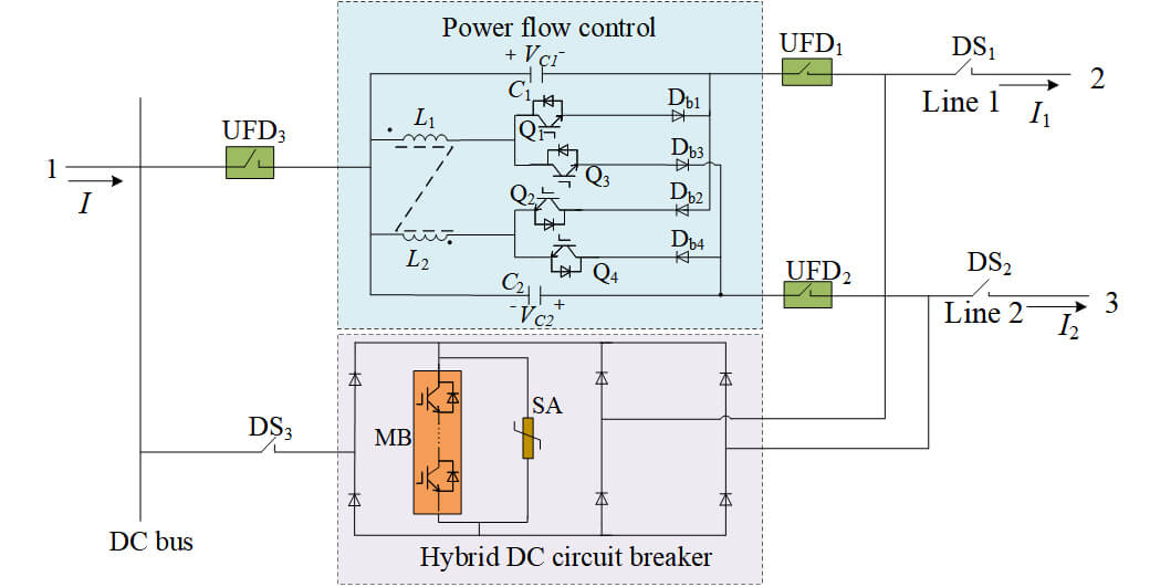
The topology of the proposed CM-HCB in this paper, which integrates both DC power flow control and fault current limiting capabilities, is shown in Fig. 1. It is primarily composed of two main parts: the PFC section and the HCB section. The PFC section comprises two capacitors(C1–C2), the coupled inductor T1 (L1–L2), four reverse-blocking Insulated Gate Bipolar Transistors (IGBTs) (Q1–Q4), four diodes (Db1–Db4). The HCB section comprises three double ultra-fast mechanical breaker (UFD1–UFD3), three mechanical disconnectors (DS1–DS3), one MB for fault current commutation and one SA for energy dissipation, which is connected in parallel with the MB. Components of MB, SA are shared, which makes it cost-effective and suitable for meshed HVDC grids.
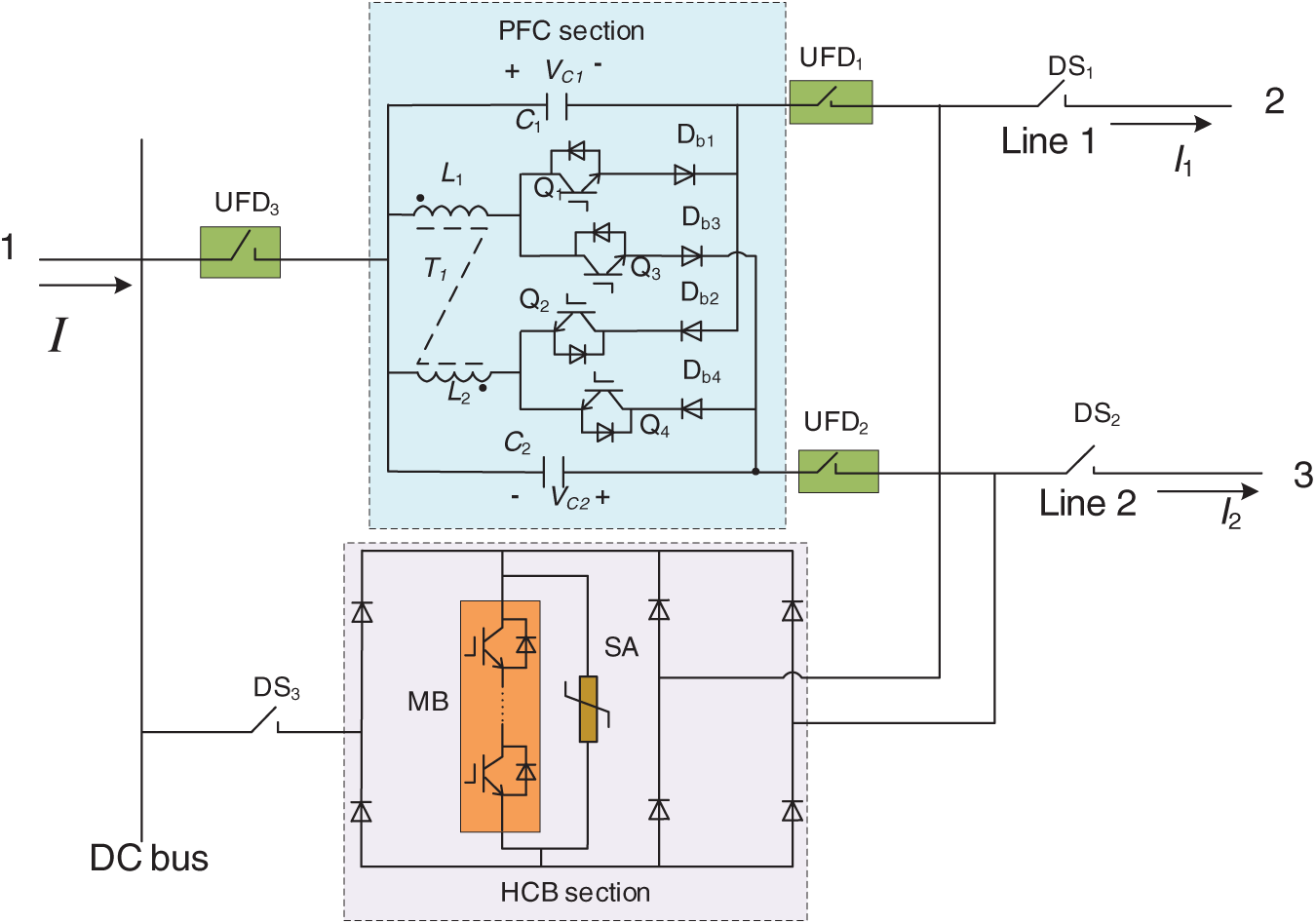
Figure 1: Topology of CM-HCB
When the DC power grid operates normally, the branches where C1, C2, L1, L2, and Q1–Q4 are located participate in the DC power flow regulation of the system, and the HCB section is blocked at this time.
When a short-circuit fault occurs on the DC line connected to the proposed CM-HCB, the HCB section starts to operate to quickly isolate the fault. During this period, UFD1–UFD2 and DS1–DS2 are used for DC branch fault isolation, while UFD3 and DS3 are dedicated to DC bus fault isolation. Meanwhile, the DC power flow control function of the PFC section is blocked.
The MB is a key component and determines the current breaking capability of the CM-HCB, as it needs to withstand the system’s pole-to-ground voltage after a DC short-circuit fault, a series connection of the IGBT modules is required. Furthermore, there are 2m + 1 diode stacks forming an extended H-bridge in the MB branch. Because the diode stacks are required to withstand the system’s transient overvoltage, and considering that their on-state loss is not significant, each diode stack needs to consist of a large number of diodes.
3 Steady-State Operation Principles
Under the steady-state operation of the DC power grid, UFD1–UFD3 and DS1–DS3 are all conducting, the MB is in the off state, the HCB section of the device is blocked. Due to the symmetry of the CM-HCB topology and system operating conditions, the steady-state operation mechanism is explained with I1 and I2 both set as positive directions. Fig. 2 shows the operating mechanism of the steady state under I1 and I2 are in a positive direction. Under this condition, the switching tubes Q1–Q4 are all turned on. As a result, capacitors C1 and C2 are bypassed, the PFC does not participate in DC grid system control—this is the bypass state of the PFC.
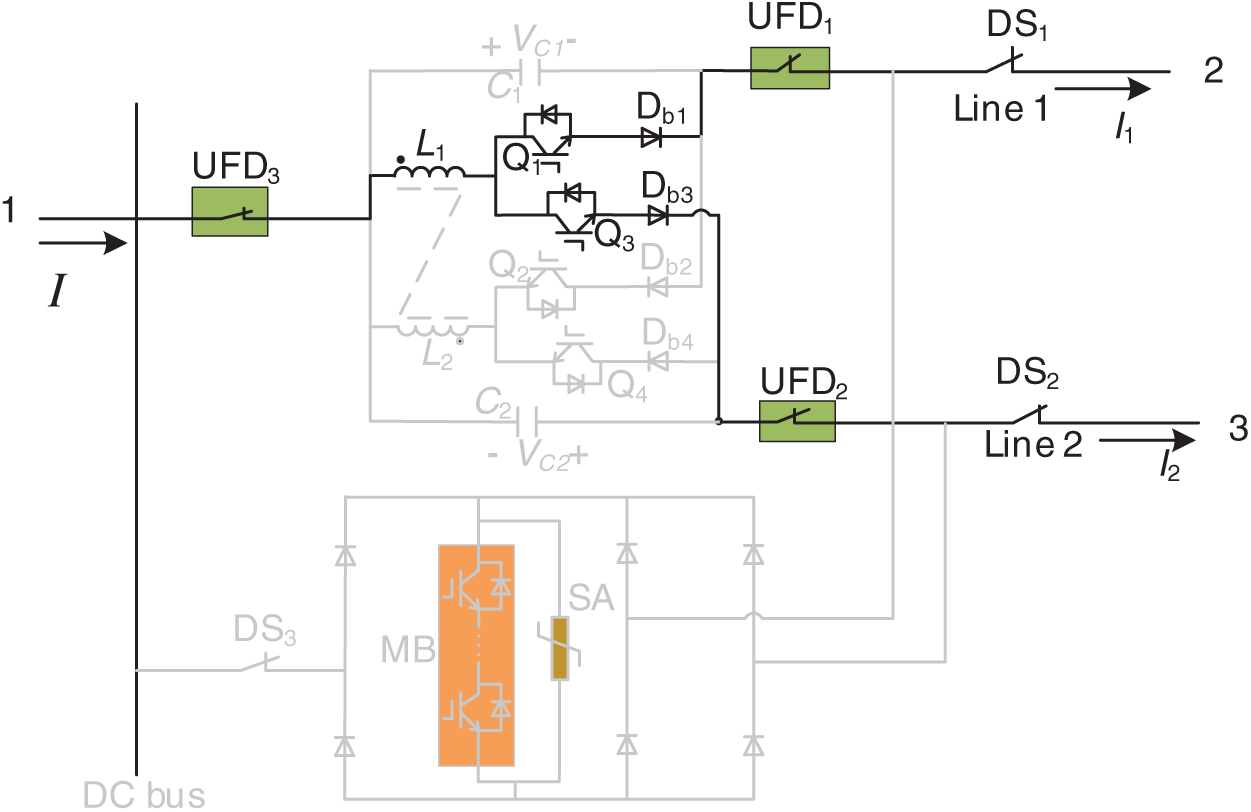
Figure 2: Steady-state operation: C1 and C2 are bypassed
To perform power flow control, the on/off states of Q1–Q4 need to be controlled according to the magnitude and direction of the DC line current. The steady-state operation principles of PFC are analyzed in detail below based on three typical operating states of the system (the positive directions of each electrical quantity are shown in Fig. 1).
3.1 I1 and I2 Are in the Positive Direction
The power flow regulation requirement is to reduce I1 and increase I2, which is equivalent to introducing a positive resistance in Line 1 and a negative resistance in Line 2, the reference direction of the capacitor voltage is the same as that in Fig. 1. When Q1–Q4 are turned off simultaneously, the voltage VC1 across capacitor C1 continues to rise, while the voltage VC2 across capacitor C2 keeps decreasing. To maintain the balance of the capacitor voltages, the energy of C1 needs to be transferred to C2.
During steady-state operation, a full switching cycle can be split into two stages. In the first stage, only Q1 is turned on to from a current loop C1-L1-Q1-Db1, as shown in Fig. 3a. During this phase, C1 transfers energy to L1, and iL1 increases linearly. Then Q1 is turned off, and only Q3 is turned on to from a current loop Q3-Db3-C2-L1, as shown in Fig. 3b. During this phase, L1 transfers energy to C2, and the current variation of C2 increases linearly. Using L1 as the energy transfer medium, energy is transferred from C1 to C2, thereby achieving the power flow control requirement of reducing I1 and increasing I2.
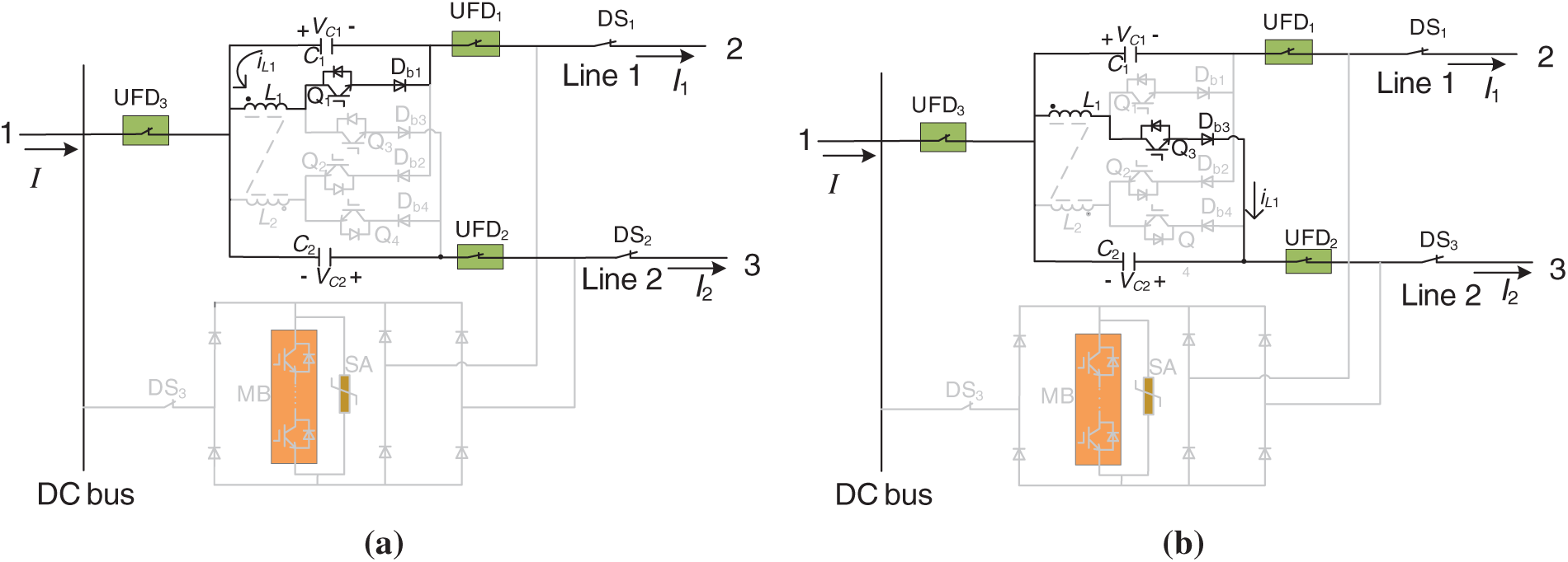
Figure 3: Operation modes of the CM-HCB with I1 and I2 positive direction. (a) Only Q1 is turned on: C1 transfers energy to L1; (b) Only Q3 is turned on: L1 transfers energy to C2
3.2 I1 and I2 Are in the Negative Direction
For the power flow control objective of reducing I1 and increasing I2, which is equivalent to introducing a positive resistance in Line 1 and a negative resistance in Line 2, the reference direction of the capacitor voltage is opposite to that in Fig. 1. First, only Q2 is turned on to from a current loop C1-Db2-Q2-L2, as shown in Fig. 4a. During this phase, C1 transfers energy to L2, and iL2 increases linearly. Then Q2 is turned off, and only Q4 is turned on to from a current loop C2-Db4-Q4-L2, as shown in Fig. 4b. In this stage, L2 transfers energy to C2. Using L2 as the energy transfer medium, energy is transferred from C1 to C2, ultimately achieving the requirement of reducing I1 and increasing I2 for power flow control.
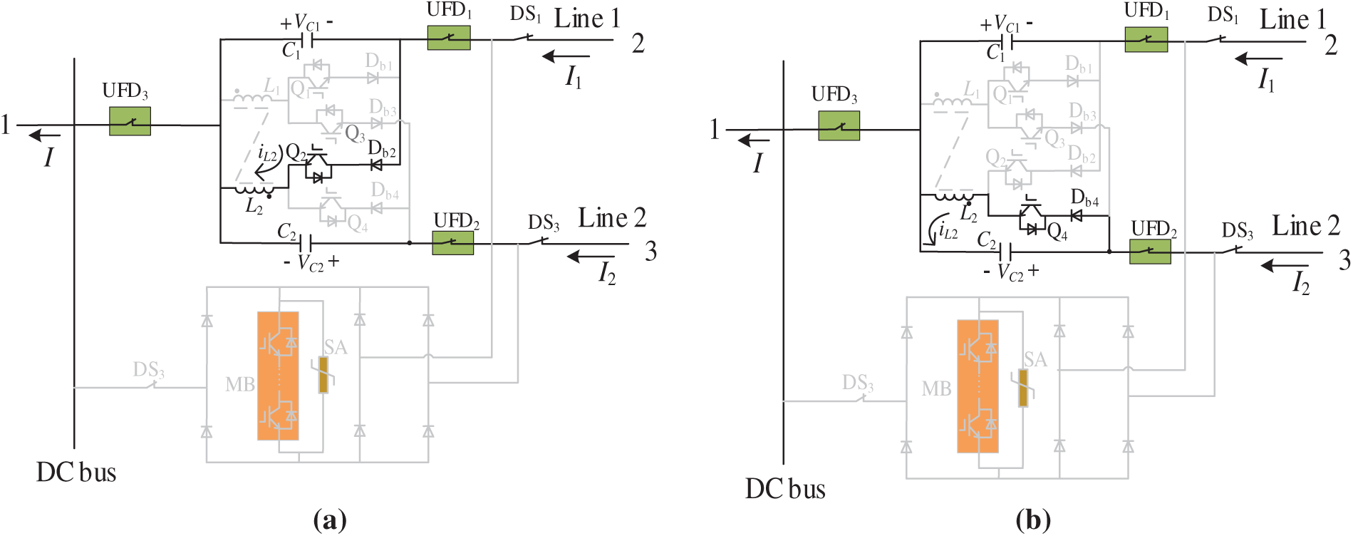
Figure 4: Operation modes of the CM-HCB with I1 and I2 negative direction. (a) Only Q2 is turned on: C1 transfers energy to L2; (b) Only Q4 is turned on: L2 transfers energy to C2
3.3 I1 and I2 Are in Different Directions
Two scenarios are considered: one where I1 is in the positive direction and I2 in the negative direction, and the other where I1 is in the negative direction and I2 in the positive direction. Leveraging the symmetry of the CM-HCB, the scenario with I1 in the positive direction, I2 in the negative direction, and the control objective of increasing I1 while decreasing I2 is selected as an example for illustration. This control process is equivalent to introducing a negative resistance in Line 1 and a positive resistance in Line 2, so the polarities of C1 and C2 are as depicted in Fig. 5. In the first step, only Q4 is turned on to form the current loop Db4-Q4-L2-C2 (see Fig. 5a). During this stage, C2 delivers energy to the coupled inductor branch L2, resulting in a linear increase in iL2. Then only Q4 is turned off, and only Q1 is turned on to establish the current loop C1-L1-Q1-Db1 (see in Fig. 5b). In this stage, due to the coupling effect of the coupled inductor, energy is transferred from L2 to L1 and further routed from L1 to C1. With L1 and L2 serving as energy transfer media, energy is transferred from C2 to C1, thereby fulfilling the power flow control requirement of increasing I1 and decreasing I2.
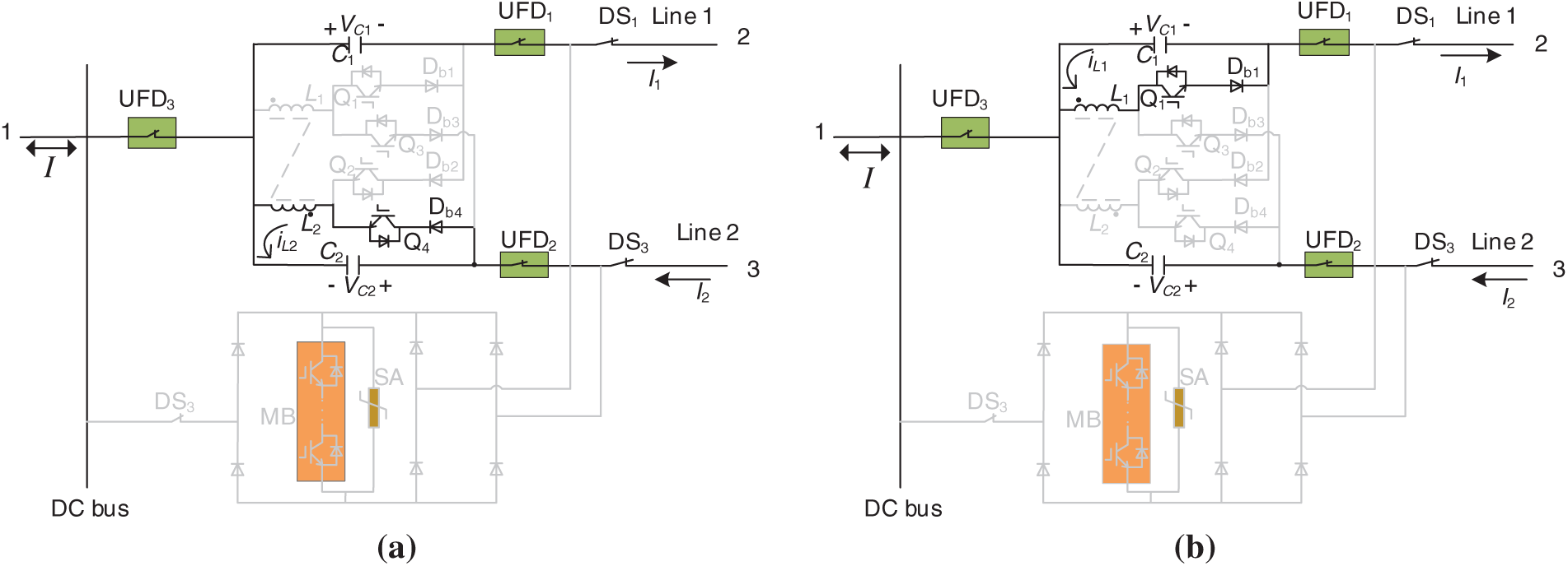
Figure 5: Operation modes of the CM-HCB with I1 and I2 different direction. (a) Only Q4 is turned on: C2 transfers energy to L2; (b) Only Q1 is turned on: L1 transfers energy to C1
Based on the above analysis, there are nine operating conditions for this PFC due to the different directions of line currents and power flow control requirements. Table 1 presents the on/off characteristics of the switching tubes and the controlled components under each condition.
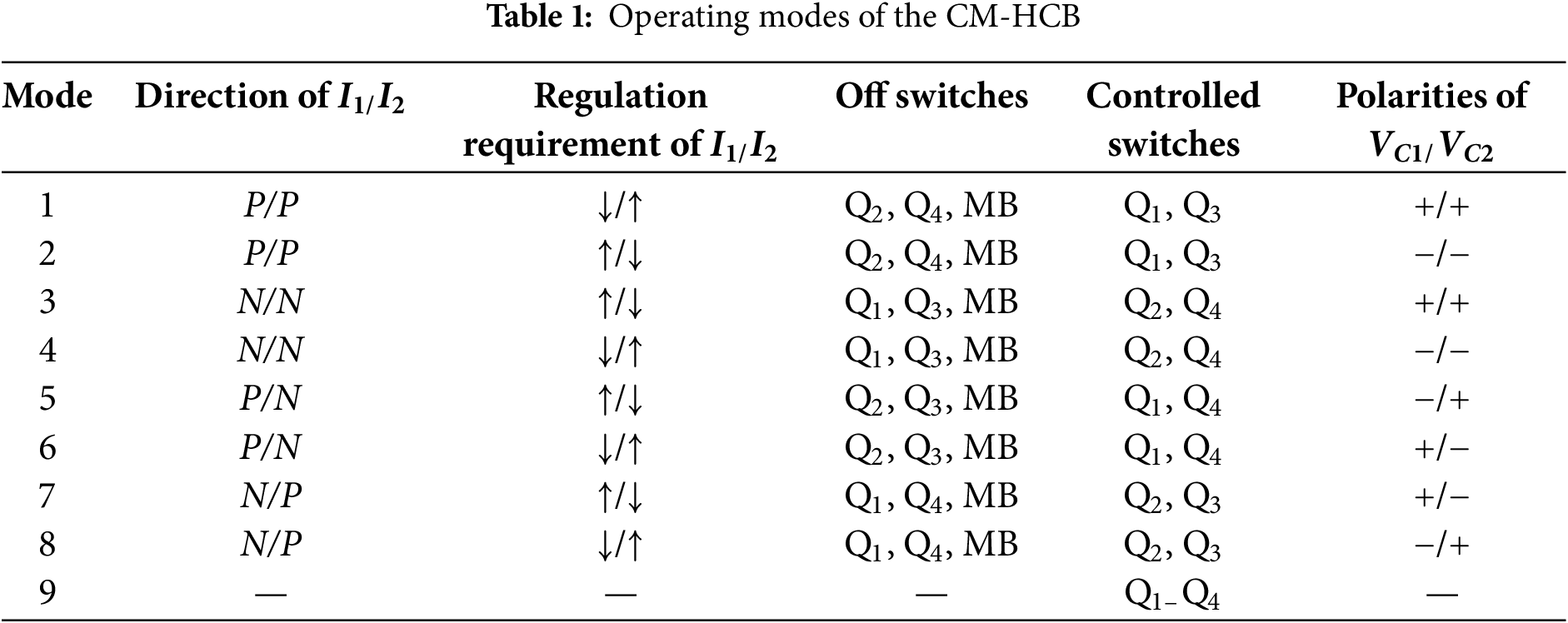
In Table 1, abbreviations P and N represent positive direction and negative direction of I1 and I2, respectively, symbols ↓/↑ represent positive current increase and decrease, respectively, symbols +/− represent the voltage polarity is the same as or opposite to the reference polarities shown in Fig. 1, respectively.
When a short-circuit fault occurs in the DC line connected to the CM-HCB device, the HCB section is activated, the IGBTs Q1–Q4 are immediately turned on according to the operating conditions to disable the DC power flow control function. Meanwhile, Q1–Q4 are reused as LCSs for short-circuit isolation. At this moment, the coupled inductor in the PFC section can function as current-limiting inductor to suppress the rising rate and peak value of the short-circuit current. Thereafter, the IGBTs in MB are turned on to commutate the fault current. Subsequently, the UFD of the fault branch is turned off under zero-current conditions to achieve initial isolation of the fault branch from the system. After removing the fault branch, the MB and DS are turned off to completely isolate the fault branch, enabling the remaining healthy branches to continue to power transmission. The operational principles under fault conditions are analyzed below based on two typical operating states of the DC power grid.
4.1 I1 and I2 Are in the Positive Direction
When both I1 and I2 are in the positive direction, assuming a permanent short-circuit fault occurs on Line 1, a large over-current from the connected healthy lines in operation and converters immediately flows to the short-circuit point. Meanwhile, the current direction of the healthy Line 2 reverses from positive to negative and increases rapidly, and the DC bus current also rises and flows into the fault point; consequently, the fault current rises sharply. The DC fault isolation strategy based on the CM-HCB is as follows:
(1) Step 1: Main branch current-conducting mode
At time t0, the fault is detected. At time t1, Q1 and Q3 are turned on, while Q2 and Q4 are turned off. The fault current is transferred to the branches where Q1 and Q3 are located, these branches then serve as the main current-carrying path, with Q1 and Q3 functioning as LCSs, as shown in Fig. 6a.
(2) Step 2: Fault current transfer mode
At time t2, the transfer of the fault current commences. The IGBT modules in MB are turned on, and part of the fault current is diverted to the MB branch. After a short delay, Q1 in the fault branch is turned off at time t3. At time t4, the current in the main branch is completely transferred to the MB branch, the current in UFD1 drops to zero, and the voltage across it is very low. Therefore, UFD1 can be open at this moment to isolate the fault point from the DC bus and other healthy DC lines, as shown in Fig. 6b.
(3) Step 3: Energy dissipation mode
The IGBT modules in MB are turned off at time t4 to interrupt the fault current and the residual energy is dissipated by the SA, as shown in Fig. 6c.
(4) Step 4: Fault isolation mode
After the current flowing through SA becomes zero at time t6, DS1 is turned off to isolate the fault point from the entire DC grid. At this point, the faulty branch has been disconnected from the system, and the healthy Line 2 has resumed normal operation. as shown in Fig. 6d.
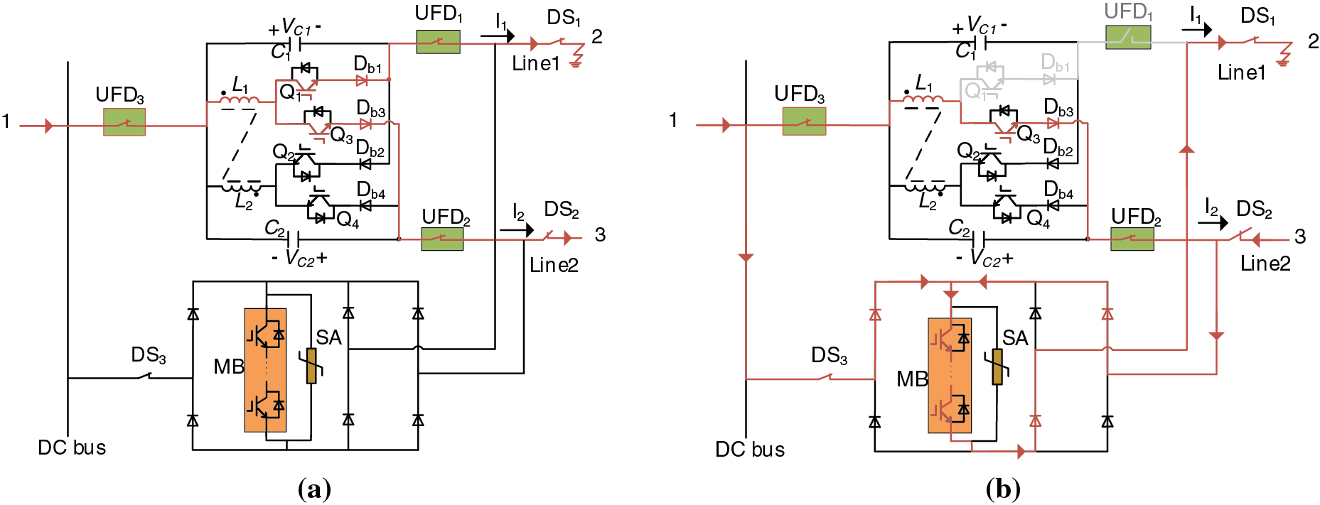
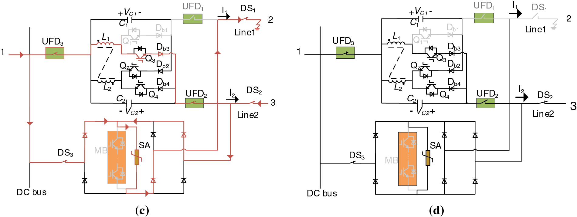
Figure 6: Operation modes of the CM-HCB with I1 and I2 positive direction. (a) Main branch current-Conducting Mode (Turn on Q1, Q3); (b) Fault current transfer mode (Turn off Q1, UFD1); (c) Energy dissipation mode (Turn off MB); (d) Fault isolation mode (Turn off DS1)
4.2 I1 Is in the Positive Direction and I2 Is in the Negative Direction
When I1 positive direction and I2 negative direction, assuming a short-circuit fault happens on the Line 1, the currents of the remaining healthy operating lines immediately flow to the short-circuit point. The DC fault isolation strategy based on the CM-HCB is as follows:
(1) Step 1: Main branch current-conducting mode
At time t0, the fault is detected. At time t1, Q1 and Q4 are turned on, while Q2 and Q3 are turned off. The fault current is transferred to the branches where Q1 and Q4 are located, these branches then serve as the main current-carrying path, with Q1 and Q4 functioning as LCSs, as shown in Fig. 7a.
(2) Step 2: Fault current transfer mode
At time t2, the IGBT modules in MB are turned on, initiating the transfer of the fault current. After a delay, the Q1 in the fault branch is turned off at time t3. At time t4, the current in the main branch is completely transferred to the MB branch, the current in the UFD1 becomes zero and the voltage across it is very low. Therefore, the UFD1 can be turned off under zero-current conditions, as shown in Fig. 7b.
(3) Step 3: Energy dissipation mode
The IGBT modules in MB is are turned off at time t4 to isolate the fault current and the remaining energy is dissipated by the SA, as shown in Fig. 7c.
(4) Step 4: Fault isolation mode
After the current flowing through SA becomes zero at time t6, the DS1 is turned off to isolate the fault point from the DC grid, as shown in Fig. 7d.
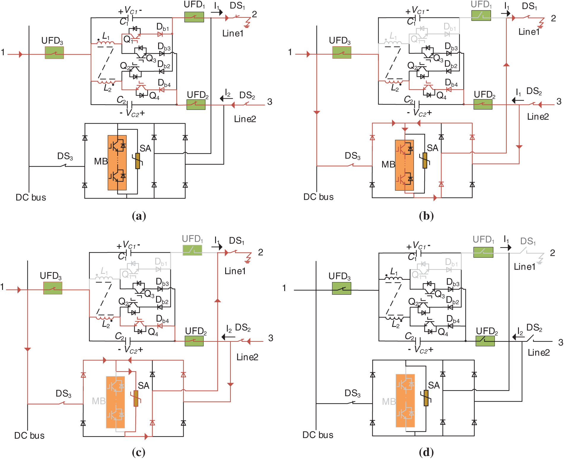
Figure 7: Operation modes of the CM-HCB with I1 positive direction and I2 negative direction. (a) Main branch current-conducting mode (Turn on Q1, Q4); (b) Fault current transfer Mode (Turn off Q1, UFD1); (c) Energy dissipation mode (Turn off MB); (d) Fault isolation mode (Turn off DS1)
5 Characteristic Analysis and Control Strategy
5.1 Characteristic Analysis of CM-HCB
Due to the symmetry of the topological structure and operating conditions of the proposed CM-HCB, the characteristic analysis and component parameter designs of CM-HCB are carried out with mode 1, in which I1 and I2 are in the positive direction (the mode corresponding to Fig. 3).
5.1.1 Design Consideration of Capacitance
Defining D is the duty cycle of Q1, while Q3 is complementary to Q1, thus the duty cycle of Q3 is 1-D. To achieve volt-second balance in primary winding of iL1, the following equation should be satisfied, i.e.,
where T is the switching period.
Thus, the relationship between the capacitor voltages VC1 and VC2 should be satisfied with the following equation as
Since the principle of the PFC section is essentially the energy transfer from C1 to C2, based on the law of conservation of energy, the following equation can be obtained as
where IC1 and IC2 are the average currents flowing through capacitors C1 and C2, respectively.
Combining Eqs. (2) and (3), yields:
Therefore, by controlling the duty cycles of the switching devices Q1 and Q3, the power flow between the two lines can be reasonably allocated.
When the DC power grid operates in a steady state, the voltage ripples ΔVC1 and ΔVC2 of capacitors C1 and C2 can be derived as follows:
where ΔT1 and ΔT2 are respectively the effective action times of capacitors C1 and C2 under the power flow control condition, which can be derived from Eq. (4) as
Combining Eqs. (2)–(6), the capacitance of the C1 and C2 can be expressed as
Therefore, the values of C1 and C2 can be obtained based on the maximum allowable voltage ripple ΔVC1 and ΔVC2.
5.1.2 Design Consideration of Coupled Inductor
During the fault conditions, the design of coupled inductor is to ensure the effect of current limitations under the fault conditions. Based on the equivalent circuit of the current limitation stage as Fig. 8, the effective inductance during current limitation stage is equal to the self-inductance L1 of coupled inductor. Thus, the increasing slope of the fault current should be lower than the system allowable increasing slope kallow can be expressed as
where L1 is the self-inductance of coupled inductor, Llimit is the original current limitation inductance of the DC stage, and the Lline is line inductance of the DC line. kallow is the system allowable current-increasing slope, which is based on the safe operation range of the system.
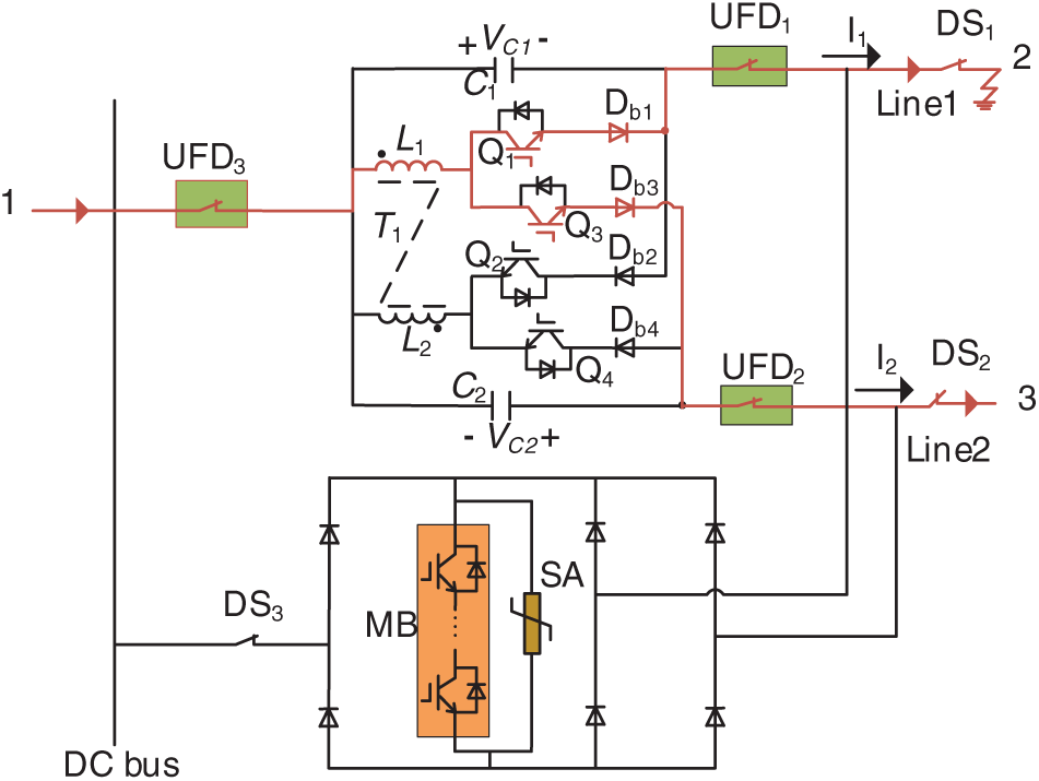
Figure 8: The equivalent circuit of the current limitation stage
Based on the above equations, the self-inductance L1 can be obtained. Due to the symmetry of the topological structure and operating conditions of the proposed CM-HCB, the self-inductance L2 can be obtained based on the same process.
During the PFC conditions, the coupled inductor T1 is used for transferring the energy between capacitors C1 and C2. The coupling coefficient k is selected to approach 1, ensuring efficient energy transfer of the system under PFC conditions.
5.2 Control Strategy of CM-HCB
5.2.1 Steady-State Control Strategy
Taking mode 1 (the mode corresponding to Fig. 3), the control strategy of PFC section during steady-state operation of the system is described. As can be seen from the above analysis, the power flow of DC line can be controlled by adjusting the duty cycle of the semiconductor switch tubes, and the block diagram of the control strategy is shown in Fig. 9.
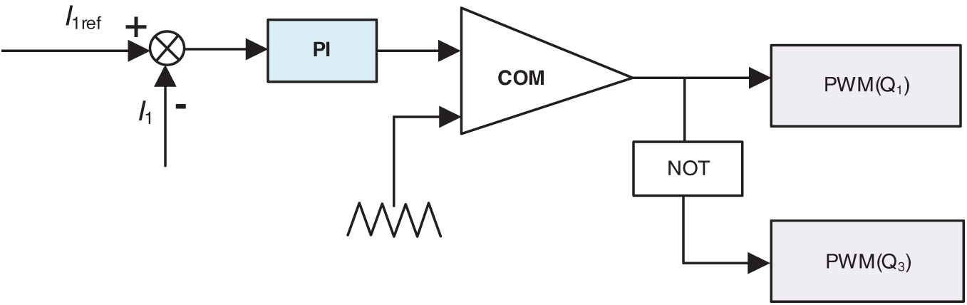
Figure 9: Block diagram of control strategy
Where, I1ref is the power flow reference regulation of Line 1, and I1 is measured current of Line 1. The error between the reference regulation and measured current is sent to a PI regulator and its output is compared with a triangular wave, and output is the PWM drive signals of switches in PFC section. To achieve power flow regulation requirement under other modes, it is only necessary to replace the DC line power flow reference values, sampling values, and the controlled switches according to Table 1.
The flowchart of DC line isolation process is shown in Fig. 10.
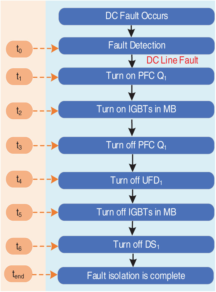
Figure 10: DC fault isolation procedure of CM-HCB
To verify the effectiveness of the proposed CM-HCB, a meshed three-terminal DC grid was constructed in the Matlab/Simulink, as illustrated in Fig. 11.
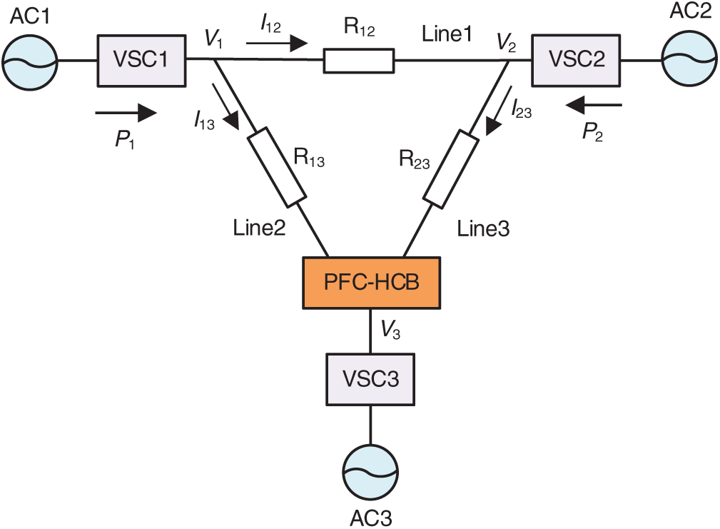
Figure 11: Meshed three-terminal DC grid with CM-HCB
The grid consists of:
(1) Terminal 1 and terminal 2 are operated in constant power mode and the injected power are set to P1 = 12 MW and P2 = 4 MW.
(2) Terminal 3 is operated as a slack DC bus and the terminal voltage is maintained at V3 = 20 kV by VSC3.
(3) The CM-HCB is located at terminal 3, C1 is inserted into Line 3, C2 is inserted into Line 2.
(4) For the CM-HCB, the switching frequency is 1 kHz, C1 = 1.2 mF, C2 = 2.1 mF and L1 = L2 = 500 µH.
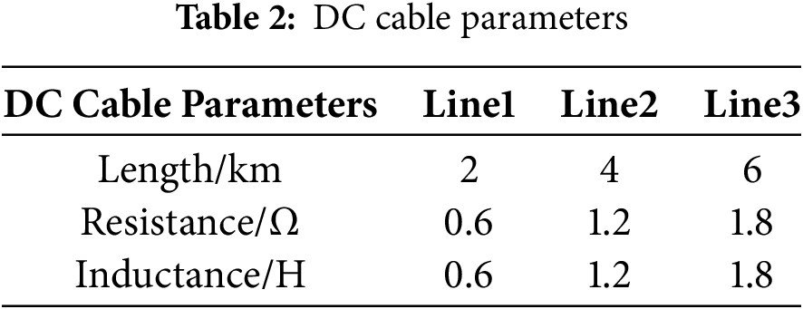
The DC parameters are shown in Table 2.
6.1 Steady-State Power Flow Control
During the period of t = 0~2 s, the CM-HCB is bypassed. The initial current of Line 1 is I12 = 97.2 A, the initial current of Line 2 is I13 = 499.3 A, and the initial current of Line 3 is I23 = 296.4 A. At t = 2 s, the CM-HCB is put into the meshed three-terminal DC grid to control the current I23 of Line 3 to 80 A. The simulation results are shown in Fig. 12. It can be seen from Fig. 12 that after the CM-HCB is put into the grid, the current I23 responds rapidly. The simulation results are consistent with the theoretical analysis conclusions, verifying the effectiveness of the proposed device for power flow control.
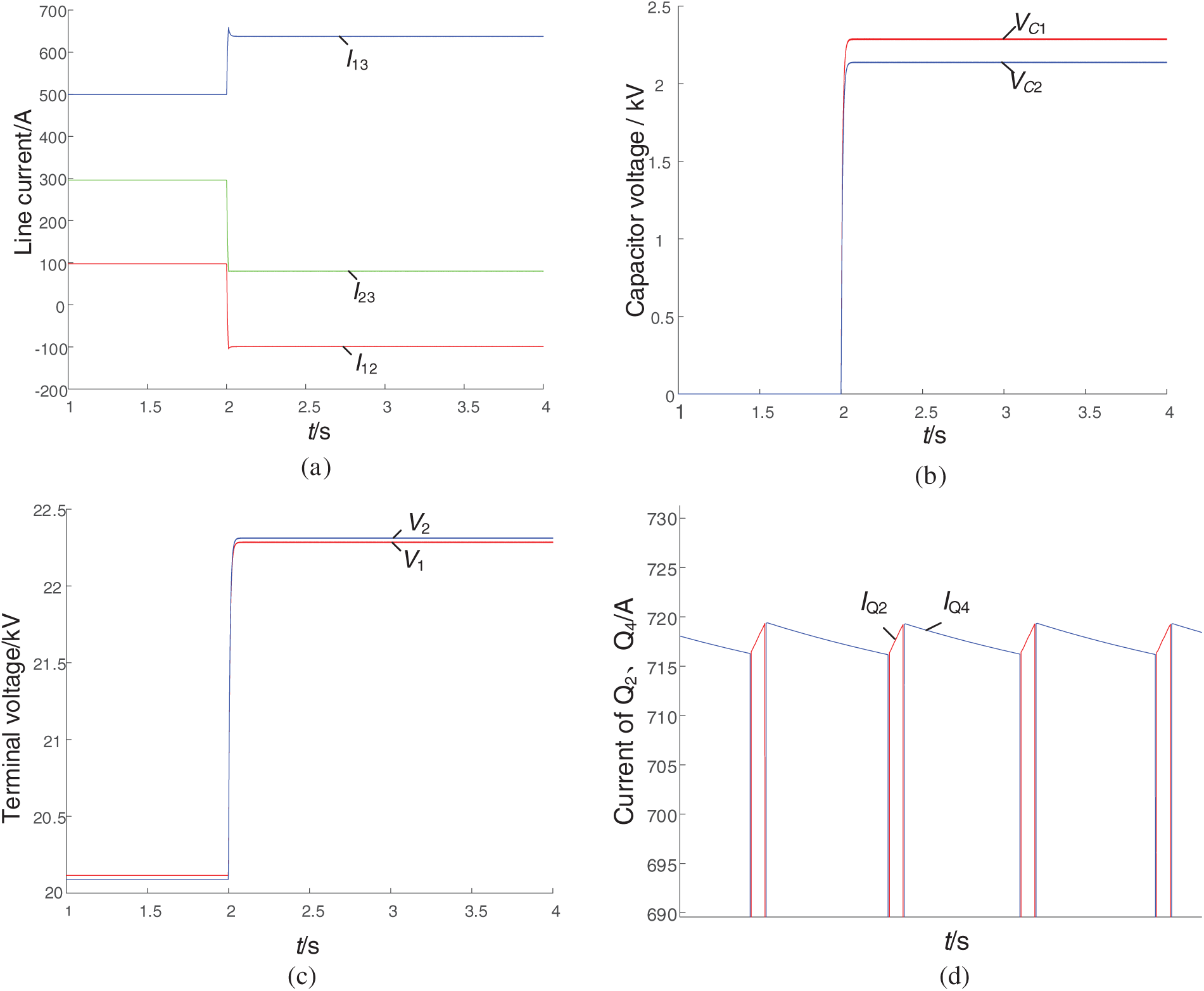
Figure 12: Waveform for steady-state power flow control. (a) Line currents; (b) Capacitor voltage; (c) Terminal voltage; (d) Current of Q2, Q4
6.2 Limitation of DC Fault Current
During the initial stage of a short-circuit fault, the coupled inductor in PFC can be utilized to limit the rising rate and peak value of the fault current by reconstructing the current flow path during the fault process. To investigate its current-limiting effect, simulations were conducted with and without coupled inductor in the meshed three-terminal DC grid when a short-circuit fault occurs at t = 2 s. The results are shown in Fig. 13a. It can be observed from the simulation that the coupled inductor significantly reduces the rising rate and peak value of the fault current during the initial phase of the short circuit.
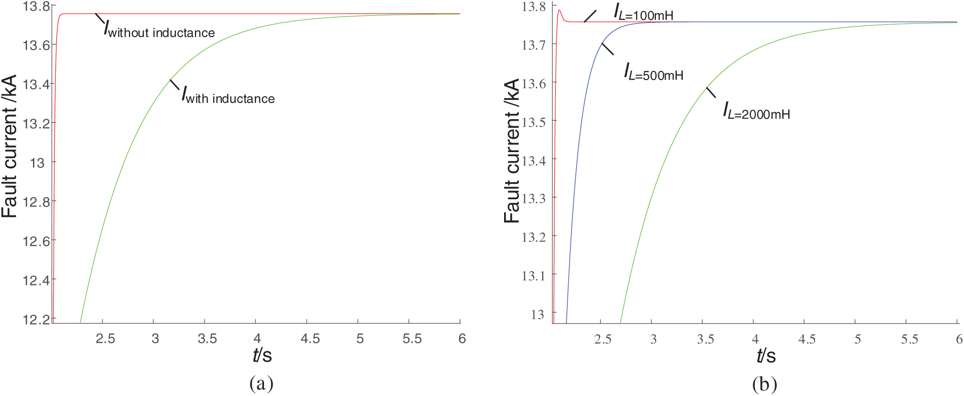
Figure 13: Fault current limiting effect of the coupled inductor. (a) Fault current with and without coupled inductor; (b) Fault current with different coupled inductor values
To further analyze the impact of different coupled inductor values on the current-limiting effect, simulations were performed with inductance values of 100, 500, and 2000 mH. The results are presented in Fig. 13b. It indicates that as the coupled inductor increases, the rising rate of the short-circuit current further decreases, demonstrating that larger inductor values provide better suppression of short-circuit currents. However, an excessively large coupled inductor is not optimal, as its value needs to be selected by comprehensively considering both the power flow control requirements and current-limiting effectiveness of the DC grid.
During the period of t = 0~4 s, the current I23 of Line 3 is controlled at 120 A, and the meshed three-terminal DC grid operates normally for power flow control. It is assumed that a short-circuit fault occurs in Line 2 at t = 4 s, and the HCB part of the CM-HCB is put into operation to isolate the fault in a timely manner. The simulation results are shown in Fig. 14. As can be seen from the Fig. 14a,b, when the fault occurs in Line 2, the currents of the remaining normally operating lines flow to the fault point, causing I13 to rise rapidly, and the capacitor in the fault line to charge quickly, increasing the capacitor voltage VC2. After detecting the fault, the LCSs Q2 and Q4 are turned on, and the PFC is blocked; subsequently, the IGBTs in MB is turned on, causing the fault current to transfer to the MB, the commutation branch current IQ4 decreases, and the transfer branch current IMB increases. Next, the Q4 in the fault branch is turned off. When the commutation current IQ4 drops to zero, a turn-off signal is sent to the UFD in the fault branch. After UFD is fully opened after a 2 ms operating time, the Q3 is turned on according to the polarity of the capacitor C2 in the fault line to form a energy dissipation loop C2-L2-Q3-Db3, dissipating the energy stored in C2, and VC2 becomes zero. Since Line1 and Line 3 resume normal operation after the CM-HCB isolates the faulty Line 2, the voltage VC1 of the capacitor C1 on Line 3 recovers to its original value after fluctuations, as shown in Fig. 14b. Subsequently, the IGBTs in MB are turned off. During the disconnection of MB, it withstands a short-term transient overvoltage, and the remaining energy is consumed by the branch where the arrester SA is located, causing IMB to decrease and the energy-dissipating branch current ISA to increase. When ISA becomes zero, the DC disconnecting switch DS is turned off, successfully isolating the fault point from the DC grid. The non-fault branches resume operation after the short circuit is cleared.
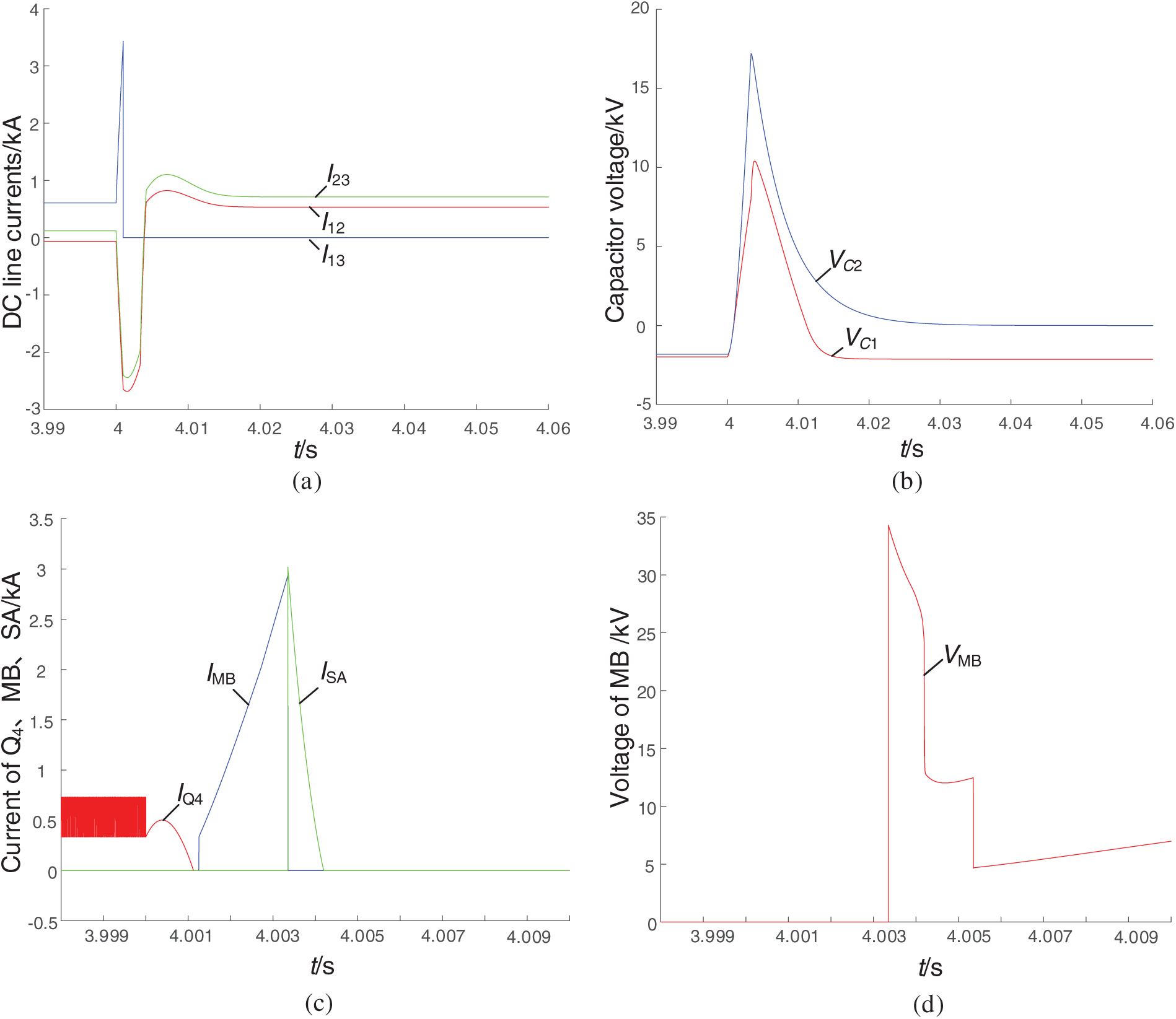
Figure 14: Waveform of short circuit control under DC line fault conditions. (a) DC line currents; (b) Capacitor voltage; (c) Current of Q4, MB, SA; (d) Voltage of MB
Now, an analysis is conducted on the voltage stress and current stress during the fault isolation process, after a fault is detected, Q2 and Q4 are turned on and act as the LCS. The fault current rises rapidly, and the maximum current flowing through Q4 at this time is 565 A, subsequently, MB is turned on, with the maximum current flowing through it reaching 2.907 kA as shown in Fig. 14c. During the commutation process, when current flows through MB, two diode stacks are connected in series with MB (as shown in Figs. 6b and 7b). This may increase the on-state voltage drop of MB; therefore, the voltage stress of MB when it is turned off is higher than the system-level voltage, and MB endures a short-term overvoltage. The maximum on-state voltage drop borne by MB is 34.29 kV, as shown in Fig. 14d.
7 Comparative Analysis with Other Solutions
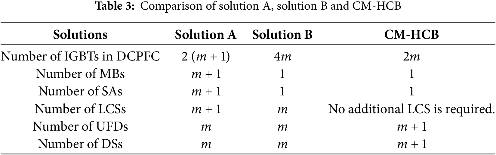
Regarding the power flow control issue and short-circuit fault isolation issue in DC power grids, current solutions either use DCPFC and HCB independently, or adopt an integrated device that combines these two functions. This section compares the number of switches used in three solutions and analyzes their economic costs. The comparison is conducted among the following three: the combination of independently used DCPFC [24] and HCB [15], hereinafter referred to as Solution A; the integrated device proposed in [27], hereinafter referred to as Solution B; the CM-HCB device proposed in this paper.
For Solution A, the DCPFC and HCB operate independently within the DC power grid. When adjusting the DC power flow of m lines, the number of IGBTs required is 2 (m + 1). In addition, for the HCB used in this solution, parts of the MBs, SAs, and LCSs are shared. Therefore, the total components include (m + 1) MBs, (m + 1) SAs, (m + 1) LCSs, m UFDs, and m DSs.
For Solution B, the device requires 4m IGBTs to achieve power flow adjustment. All lines share one MB and one SA, but additional UFDs and DSs are needed. Thus, it comprises 1 MB, 1 SA, m LCSs, m UFDs, and m DSs.
For the CM-HCB device proposed in this paper, a total of 2m IGBTs are needed for power flow control. During fault isolation, the switches used for power flow control can be reused as LCSs. Therefore, the device includes 1 MB, 1 SA, (m + 1) UFDs, (m + 1) DSs, and no additional LCSs are required.
The reason why the device in solution B uses one fewer UFD and one fewer DS than the proposed CM-HCB device is as follows: In the former, when a DC bus fault occurs, all UFDs and DSs connected to the DC bus must be tripped to clear the fault. In contrast, the latter only requires one UFD and one DS to trip, while the other lines can still operate normally. Moreover, the HCB section of the CM-HCB can also be used to handle faults occurring on DC branches.
The comparison results of the three solutions are presented in Table 3. As shown in Table 3, the proposed CM-HCB device uses fewer switches compared to both the independent DCPFC-HCB combination (Solution A) and the device in [27] (Solution B). Although the CM-HCB uses one more UFD and one more DS than the device in [27], the cost of UFDs and DSs is significantly lower than that of IGBT modules. Therefore, the proposed CM-HCB has greater advantages in terms of economic benefits.
This paper proposes a composite CM-HCB, which employs the component sharing mechanism to successfully integrate the power flow control, current limiting, and fault-current interruption functionalities, thereby directly addressing the issues of high costs and low utilization. The topology, operation principle, and control strategy of the CM-HCB are detailed, and a meshed three-terminal DC grid simulation platform is established in Matlab/Simulink for simulation validation. The results show that the proposed CM-HCB has the following advantages:
(1) It integrates three functions: DC power flow control, fault current limiting, and fault isolation. During normal system operation, it can flexibly perform DC power flow control. At the initial stage of a short-circuit fault in the system, it can limit the rise rate and peak value of the fault current, reduce the breaking current requirements for the HCB section, and effectively isolate the fault.
(2) Multiple ports of DC lines share a single MB and a single SA. Additionally, the LCSs in the main current-carrying branch can be reused as power flow control switches, which helps reduce on-state losses. Compared with the separate use of DCPFCs and HCBs for DC power flow control and short-circuit isolation, the proposed CM-HCB uses fewer semiconductor switching devices, thus significantly reducing the overall cost of the DC power grid.
Besides, the proposed CM-HCB is based on the conventional current-commutation paralleled HCB (P-HCB). However, the P-HCB suffers from the problem that the continuous increase in fault current during the current-commutation process results in high requirements for breaking capacity and low interruption speed. Future research can explore the mechanisms of component sharing and function integration based on the ultra-fast series-type HCB proposed in [28,29], aiming to construct an upgraded ultra-fast and low-cost DC circuit breaker that inherits the core advantages of CM-HCB’s. Meanwhile, future research can also involve risk management for the CM-HCB by referencing the framework in [30], with consideration of the evolving market dynamics.
Acknowledgement: Not applicable.
Funding Statement: This research is funded by Youth Talent Growth Project of Guizhou Provincial Department of Education (No. Qianjiaoji [2024] 21) and National Natural Science Foundation of China (No. 62461008 and No. 52507211) and Guizhou Provincial Key Technology R&D Program (No. [2024] General 049).
Author Contributions: The authors confirm contribution to the paper as follows: Conceptualization, Xiaoya Chen and Chao Zhang; methodology, Xufeng Yuan and Wei Xiong; writing—original draft preparation, Xiaoya Chen and Chao Zhang; writing—review and editing, Huajun Zheng and Zhiyang Lu; supervision, Yutao Xu and Zhukui Tan. All authors reviewed the results and approved the final version of the manuscript.
Availability of Data and Materials: Data supporting this study are included within the article.
Ethics Approval: Not applicable.
Conflicts of Interest: The authors received no specific funding for this study.
References
1. Fattaheian-Dehkordi S, Abbaspour A, Fotuhi-Firuzabad M, Lehtonen M. A distributed framework for intense ramping management in distribution networks. IEEE Trans Smart Grid. 2023;14(1):315–27. doi:10.1109/tsg.2022.3199811. [Google Scholar] [CrossRef]
2. Tan H, Yu H, Chen T, Deng H, Hu Y. Adaptive multi-objective energy management strategy considering the differentiated demands of distribution networks with a high proportion of new-generation sources and loads. Energy Eng. 2025;122(5):1949–73. doi:10.32604/ee.2025.062574. [Google Scholar] [CrossRef]
3. Pourfaraj A, Iman-Eini H, Hamzeh M, Langwasser M, Liserre M. A thyristor-based multiline hybrid DCCB in protection coordination with MMC in multiterminal DC grids. IEEE J Emerg Sel Top Power Electron. 2024;12(5):5055–64. doi:10.1109/JESTPE.2024.3447094. [Google Scholar] [CrossRef]
4. Yu X, Jia G, Liu X, Yuan Y, Li M. A novel current-limiting hybrid DC breaker based on thyristors. Energy Rep. 2023;9(9):983–91. doi:10.1016/j.egyr.2023.04.150. [Google Scholar] [CrossRef]
5. Qin B, Liu W, Li H, Ding T, Ma K, Liu T. Impact of system inherent characteristics on initial-stage short-circuit current of MMC-based MTDC transmission systems. IEEE Trans Power Syst. 2022;37(5):3913–22. doi:10.1109/TPWRS.2021.3140061. [Google Scholar] [CrossRef]
6. Zhang X, Yang J, Wu Z, Zhang B, Qi L. A novel thyristor-controlled voltage-source-based forced resonant mechanical DC circuit breaker. IEEE Trans Power Electron. 2023;38(11):14563–72. doi:10.1109/TPEL.2023.3293874. [Google Scholar] [CrossRef]
7. Pogulaguntla A, Dsa D, Venkata Yagna G, Naik Banavath S, Laercio Carvalho E, Chub A, et al. Air-core coupled in ductor-based modular solid-state circuit breaker with reduced components for DC buildings. IEEE J Emerg Sel Topics Power Electron. 2025;13(3):2988–99. doi:10.1109/jestpe.2024.3485735. [Google Scholar] [CrossRef]
8. Wang W, Fang C, Zhao F, He L, Chen D, Shuai Z, et al. A self-powered bidirectional DC solid-state circuit breaker based on SiC JFETs for DC microgrids. IEEE Trans Ind Electron. 2025;72(4):3622–32. doi:10.1109/TIE.2024.3454471. [Google Scholar] [CrossRef]
9. Roshani Diz M, Vahidi B, Rastegar H. A novel model of superconducting tape-based hybrid DC circuit breaker for monopolar and bipolar HVDC grid. Results Eng. 2025;25:104259. doi:10.1016/j.rineng.2025.104259. [Google Scholar] [CrossRef]
10. Zhang S, Zou G, Wei X, Zhou C, Zhou K. Improved integrated hybrid DC circuit breaker for MTDC grid protection. IEEE Trans Circuits Syst II Express Briefs. 2022;69(12):4999–5003. doi:10.1109/TCSII.2022.3195760. [Google Scholar] [CrossRef]
11. Yin J, Lang X, Duan J, Liang S, Li X. Interruption characteristics of self-powered hybrid DC circuit breaker with synergistic effect of step-down and divided current. Int J Electr Power Energy Syst. 2024;159(8):109989. doi:10.1016/j.ijepes.2024.109989. [Google Scholar] [CrossRef]
12. Zhang S, Zou G, Gao F, Shi D, Wei X. Thyristor-based multiport hybrid DC circuit breaker for multiterminal DC grid protection. IEEE Trans Ind Electron. 2024;71(11):14197–207. doi:10.1109/TIE.2024.3368139. [Google Scholar] [CrossRef]
13. Saminathan N, Aditya P, Banavath SN, Lidozzi A, Di Benedetto M, Vengadarajan A. Bidirectional hybrid DC circuit breaker with zero voltage and current switching for radar power system. IEEE Open J Ind Appl. 2024;5:224–34. doi:10.1109/ojia.2024.3399603. [Google Scholar] [CrossRef]
14. Li C, Liang J, Wang S. Interlink hybrid DC circuit breaker. IEEE Trans Ind Electron. 2018;65(11):8677–86. doi:10.1109/tie.2018.2803778. [Google Scholar] [CrossRef]
15. Xiao H, Xu Z, Xiao L, Gan C, Xu F, Dai L. Components sharing based integrated HVDC circuit breaker for meshed HVDC grids. IEEE Trans Power Deliv. 2019;35(4):1856–66. doi:10.1109/TPWRD.2019.2955726. [Google Scholar] [CrossRef]
16. Kontos E, Schultz T, MacKay L, Ramirez-Elizondo LM, Franck CM, Bauer P. Multiline breaker for HVdc applications. IEEE Trans Power Deliv. 2018;33(3):1469–78. doi:10.1109/TPWRD.2017.2754649. [Google Scholar] [CrossRef]
17. Pourmirasghariyan M, Gharehpetian GB, Gomis-Bellmunt O, Campos-Gaona D, Papadopoulos PN. Enlarged operational area of an interline DC power flow controller via adaptive droop control for multi-terminal HVDC systems. Int J Electr Power Energy Syst. 2025;164(1):110430. doi:10.1016/j.ijepes.2024.110430. [Google Scholar] [CrossRef]
18. Ye Y, Zhang X, Jin J, Wang Y, Yang X. A multiport current flow controller for meshed multiterminal DC grids. IEEE Trans Power Electron. 2023;38(4):5479–89. doi:10.1109/TPEL.2022.3230094. [Google Scholar] [CrossRef]
19. Jovcic D, Hajian M, Asplund G, Zhang H. Power flow control in DC transmission grids using mechanical and semiconductor based DC/DC devices. In: 10th IET International Conference on AC and DC Power Transmission (ACDC 2012). Birmingham, UK: Institution of Engineering and Technology; 2012. 43 p. doi:10.1049/cp.2012.1972. [Google Scholar] [CrossRef]
20. Zhang J, Liu Y, Zang J, Wang J, Zhou J, Shi G, et al. A multiport DC power flow controller embedded in modular multilevel DC transformer. IEEE Trans Ind Electron. 2023;70(5):4831–41. doi:10.1109/TIE.2022.3187584. [Google Scholar] [CrossRef]
21. Guo H, Chen W, Zhu Y, Zhu M. An expandable interline DC power flow controller. IEEE Trans Power Electron. 2024;39(1):826–36. doi:10.1109/TPEL.2023.3325225. [Google Scholar] [CrossRef]
22. Abbasipour M, Liang X. Power flow study of MT-HVDC grid compensated by multiport interline DC power flow controller. IEEE Trans Ind Appl. 2023;59(4):4786–96. doi:10.1109/TIA.2023.3258937. [Google Scholar] [CrossRef]
23. Zhong X, Zhu M, Li Y, Wang S, Wang H, Cai X. Modular interline DC power flow controller. IEEE Trans Power Electron. 2020;35(11):11707–19. doi:10.1109/TPEL.2020.2989197. [Google Scholar] [CrossRef]
24. Wu W. Research on multi-port DC power flow controller [dissertation]. Beijing, China: Beijing Jiaotong University; 2021. (In Chinese). doi:10.26944/d.cnki.gbfju.2021.000171. [Google Scholar] [CrossRef]
25. Mokhberdoran A, Gomis-Bellmunt O, Silva N, Carvalho A. Current flow controlling hybrid DC circuit breaker. IEEE Trans Power Electron. 2018;33(2):1323–34. doi:10.1109/TPEL.2017.2688412. [Google Scholar] [CrossRef]
26. Wang S, Ming W, Liu W, Li C, Ugalde-Loo CE, Liang J. A multi-function integrated circuit breaker for DC grid applications. IEEE Trans Power Deliv. 2020;36(2):566–77. doi:10.1109/TPWRD.2020.2984673. [Google Scholar] [CrossRef]
27. Yu J, Zhang Z, Xu Z. A multi-port hybrid circuit breaker integrated with power flow control ability. IET Gener Transm Distrib. 2022;16(21):4356–69. doi:10.1049/gtd2.12604. [Google Scholar] [CrossRef]
28. Yang H, Zhang C, Yuan X, Xiong W, Luo F, Liu Z, et al. An H-bridge based diode clamping switched SHCB with bi-directional interruption and residual energy recuperation ability. IEEE J Emerg Sel Top Power Electron. 2025;PP(99):1. doi:10.1109/JESTPE.2025.3583763. [Google Scholar] [CrossRef]
29. Luo F, Zhang C, Yuan X, Xiong W, Zheng H, Liu Z, et al. A series-type hybrid circuit breaker based on flying capacitor multilevel injector with balanced switching operation and current limiting capability. IEEE J Emerg Sel Top Power Electron. 2024;12(4):4052–65. doi:10.1109/JESTPE.2024.3394516. [Google Scholar] [CrossRef]
30. Xiao D, Peng Z, Lin Z, Zhong X, Wei C, Dong Z, et al. Incorporating financial entities into spot electricity market with renewable energy via holistic risk-aware bilevel optimization. Appl Energy. 2025;398:126449. doi:10.1016/j.apenergy.2025.126449. [Google Scholar] [CrossRef]
Cite This Article
 Copyright © 2026 The Author(s). Published by Tech Science Press.
This work is licensed under a Creative Commons Attribution 4.0 International License , which permits unrestricted use, distribution, and reproduction in any medium, provided the original work is properly cited.
 Downloads
 Citation Tools