
 Submit a Paper
 Propose a Special lssue
 Open Access
ARTICLE

Sensorless Speed Control of Synchronous Reluctance Motor Using an Advanced Fictitious Flux Estimation Including Cross Coupling Effect
1 Department of Electrical Engineering, University of Padova, Padova, 35131, Italy
2 Dana Service and Assembly Center (SAC), Veneto, 35035, Italy
* Corresponding Author: Nicola Bianchi. Email:
(This article belongs to the Special Issue: Energy Transition in the Transport Sector: Challenges and Opportunities)
Energy Engineering 2026, 123(3), 22 https://doi.org/10.32604/ee.2025.073434
Received 18 September 2025; Accepted 24 December 2025; Issue published 27 February 2026
 View Full Text
 Download PDF
Abstract
Synchronous reluctance motors (SynRM) are widely employed in industrial applications due to their high robustness, low cost, and absence of permanent magnets. In recent years, significant research efforts have focused on improving the controllability and efficiency of SynRM. Accurate rotor position information is essential for the controller to generate appropriate current and voltage references corresponding to the desired speed and load torque. Shaft-mounted position sensors are generally undesirable because of their high cost, sensitivity to harsh operating conditions, maintenance requirements, and reduced reliability in environments characterized by high vibration. Consequently, sensorless control techniques that estimate rotor position using measured stator currents and voltages have attracted increasing attention. However, magnetic saturation, parameter nonlinearities, and cross-coupling effects significantly degrade position estimation accuracy and may compromise the stability of sensorless SynRM drives. In this paper, a nonlinear SynRM model is developed using finite element analysis (FEA) to accurately capture magnetic saturation and cross-coupling effects, thereby providing a precise representation of the machine’s electromagnetic behavior under varying load and flux conditions. A series of magnetostatic FEA simulations is performed. To reduce computational complexity, only one motor pole is analyzed by applying anti-periodic boundary conditions along the domain sides and enforcing a zero magnetic vector potential on the external stator boundary. Nonlinear iron material properties are modeled using the appropriate B-H curve. The simulations are carried out by imposing d- and q-axis current components and computing the corresponding flux linkages and electromagnetic torque. Based on these results, both apparent and incremental inductances are extracted and incorporated into the control algorithm. An advanced fictitious flux linkage method combined with a phase-locked loop (PLL) is employed for accurate rotor position estimation. Simulation results confirm that the proposed sensorless control strategy ensures stable operation and high position estimation accuracy over the entire speed range.Keywords
The Synchronous Reluctance Motor (SynRM) has gained considerable attention in industrial applications due to its simple and robust structure, high efficiency, high torque density, and the absence of permanent magnets [1–5]. The independence from rare-earth materials makes SynRMs cost-effective and environmentally sustainable alternatives to conventional AC machines [4]. Furthermore, the absence of rotor windings and permanent magnets results in reduced rotor losses and torque characteristics that are insensitive to temperature variations [6]. The stator structure is similar to that of an induction motor, featuring three-phase sinusoidally distributed windings supplied by balanced currents [4,7,8], while offering higher torque density and lower manufacturing cost compared to induction motors [9–11].
High-performance SynRM drives require accurate rotor position information to achieve precise speed and torque control [4,12,13]. Although shaft-mounted position sensors can provide this information, their use is often limited by increased cost, reduced reliability in harsh environments, sensitivity to vibration and temperature, and installation constraints [13–16]. Consequently, sensorless control strategies have become increasingly attractive for reliable and low-cost SynRM drive systems.
Recent advances in microcontrollers and power electronics have enabled the development of sensorless SynRM control schemes based on electrical signal measurements [4,17,18]. Among these, model-based position estimation techniques are particularly appealing since they do not require high-frequency voltage injection. However, the strong magnetic saliency of the SynRM rotor introduces significant nonlinearities due to magnetic saturation and cross-coupling, which complicate accurate stator flux and position estimation and may degrade estimator stability [19–21]. Many existing approaches simplify the problem by neglecting these nonlinear effects and relying on voltage-model-based flux estimation [22,23].
The fictitious flux linkage concept, originally proposed in [24,25] and further developed in [26,27], enables rotor position estimation by aligning the fictitious flux with the rotor d-axis. Nevertheless, accurate stator flux estimation remains critical, particularly when magnetic saturation and cross-coupling are present [28]. Recent studies have highlighted the necessity of incorporating nonlinear magnetic effects for reliable sensorless operation [29–31].
In this paper, a nonlinear SynRM model including magnetic saturation and cross-coupling effects is developed using Finite Element Analysis (FEA)-based magnetic mapping. The resulting nonlinear flux linkage lookup tables are integrated into a combined voltage and current model for accurate stator flux estimation. A fictitious flux linkage is then computed and used in conjunction with a Phase-Locked Loop (PLL) to estimate the rotor position. Steady-state and dynamic simulation results validate the effectiveness and robustness of the proposed sensorless control strategy.
2 Modelling of Nonlinear SynRM
To design the controller of the nonlinear SynRM, it is first necessary to develop an accurate nonlinear magnetic model of the machine. This model can be constructed either from measured magnetic characteristics obtained on a test bench or via finite element analysis (FEA) [32–34].
In this section, the nonlinear model of the selected SynRM is developed considering magnetic cross-coupling effects through FEA. To obtain accurate results, a series of magnetostatic FEM analyses is performed following the approach in [35–37]. To enhance computational efficiency while preserving precision, only one pole of the motor is analyzed, with anti-periodic boundary conditions applied on the lateral boundaries and a zero magnetic vector potential enforced on the external stator surface. Nonlinear iron material properties, characterized by the appropriate B–H curve, are adopted. The analyses are conducted by imposing the d- and q-axis current components and computing the corresponding d- and q-axis flux linkages along with the electromagnetic torque.
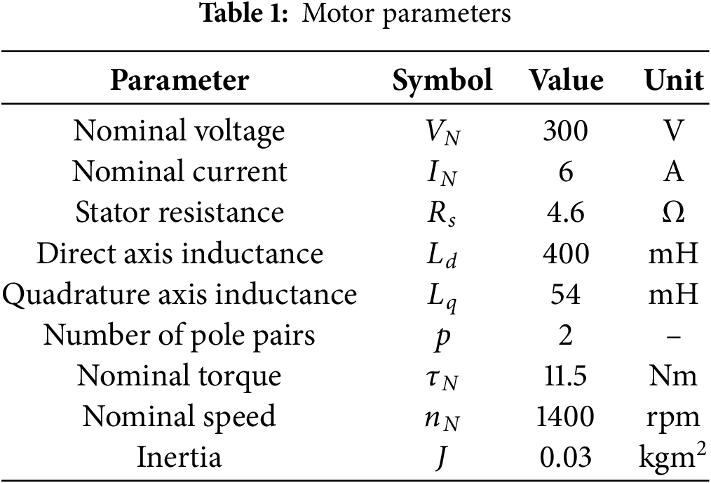
From the FEA results, and using Eqs. (2), (6), and (7), the stator resistance as well as the apparent and incremental inductances of the motor are determined. These parameters are subsequently used in the controller design and are summarized in Table 1.
The nonlinear equations of the SynRM model are given by
Rearranging the above equations yields
For the nonlinear SynRM, the flux linkages
The flux linkage variations can be expressed as
From Eq. (3), the incremental inductances are defined as
At any operating point
Using Eq. (3), the current variations can then be computed as
Let us remember that the cross incremental inductances Idq and Iqd are equal. As a consequence, the inertance
Furthermore, the electromagnetic torque
where
The nonlinear motor model, shown in Fig. 1, is based on Eqs. (2), (6) and (7).
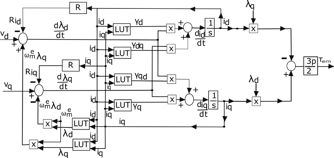
Figure 1: Dynamic motor model
The results obtained from the model shown in Fig. 1 are presented in Fig. 2a,b. These results confirm that a nonlinear model of the SynRM has been successfully developed for control purposes.
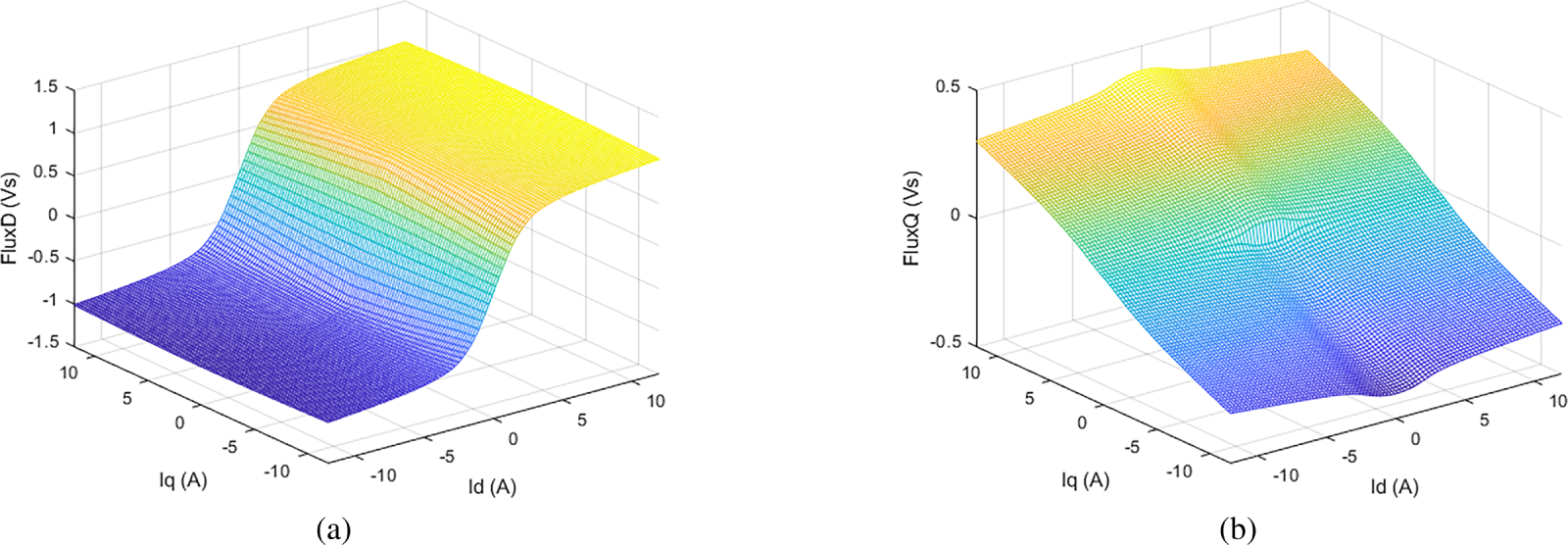
Figure 2: (a) Nonlinear d-axis flux
2.1 Nonlinear d-Axis Flux Linkage
Fig. 2a illustrates that the d-axis flux linkage exhibits nonlinear behavior and is influenced by both the direct- and quadrature-axis currents, reflecting the presence of cross-coupling effects.
2.2 Nonlinear q-Axis Flux Linkage
Fig. 2b illustrates the nonlinear q-axis flux linkage, which is influenced by both the direct- and quadrature-axis currents, including the magnetic cross-coupling effect. It is noteworthy that a significant variation occurs at
3 Design of the Advanced Fictitious Flux Estimator
This section integrates two complementary methods, a voltage integrator and a flux observer, accounting for nonlinear magnetic cross-coupling, to design an advanced fictitious flux linkage estimator. To accurately estimate the rotor position, the fictitious flux linkage is derived from the stable stator flux linkage of the model and processed through a phase-locked loop (PLL) controller for medium- and high-speed operations.
The voltage equations of the SynRM in the stationary
where
At zero or low speed, the back-EMF is negligible, and Eq. (9) fails to provide an accurate estimate of the
To estimate the rotor-frame currents
The incremental inductance matrix of the nonlinear magnetic model, obtained from FEA, is given in Eq. (4). The flux linkage vector
where the tilde denotes that the flux is calculated from the current model. The corresponding flux in the stationary frame is
Here,
Accurate rotor position estimation requires that
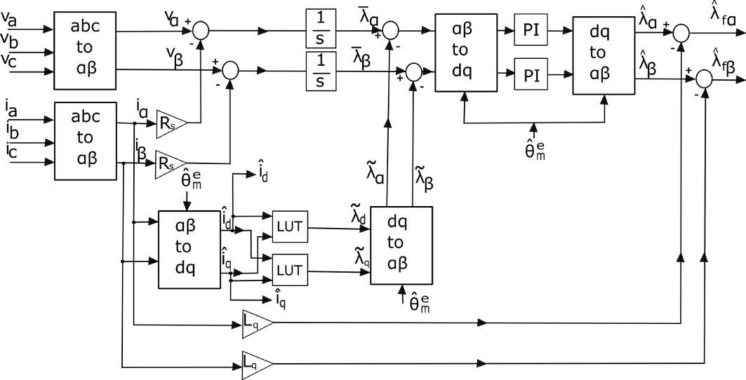
Figure 3: Combined model of the voltage integrator and flux observer for estimating the SynRM stator flux linkage
3.3 Fictitious Flux Linkage Estimation
The flux linkage
where the uppercase L denotes the apparent inductances, which are defined at any operating point
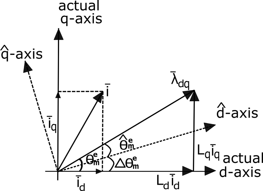
Figure 4: Representation of the synchronous reference frame flux linkage
The following remarks are noteworthy:
It is not necessary to estimate the magnitude of the d-axis flux linkage; only its direction needs to be determined. Therefore, any vector aligned with
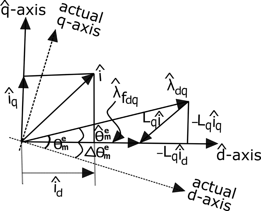
Figure 5: Estimated synchronous reference frame flux linkage
3.4 Determining the Fictitious Flux Linkage Vector
The fictitious flux linkage vector is defined as
Multiplying Eq. (15) by
The estimated electromagnetic torque is then calculated as
The combined model of the voltage integrator and flux observer is shown in Fig. 3.
3.5 Rotor Position Estimation Using a Phase-Locked Loop (PLL) Controller
A PLL controller given in Fig. 6 is employed to estimate the rotor position [39,40].
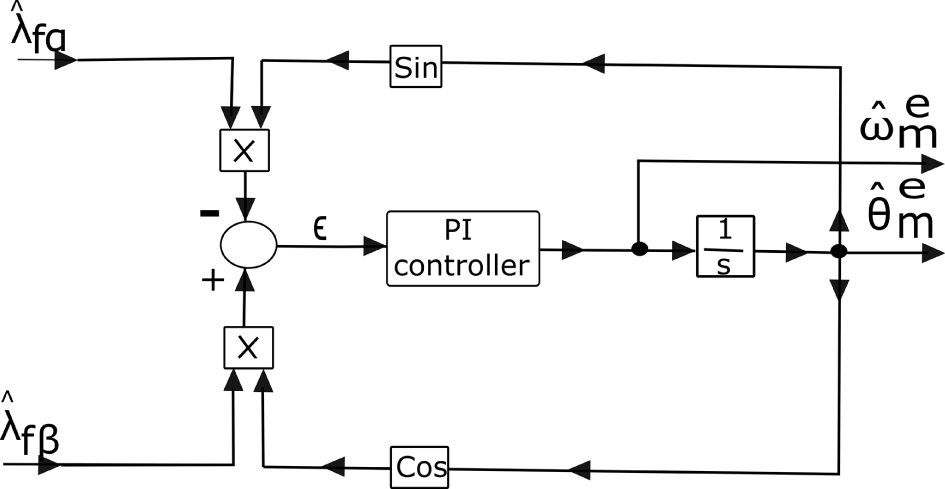
Figure 6: PLL controller for speed and rotor position estimation
Fig. 7 illustrates the vectors
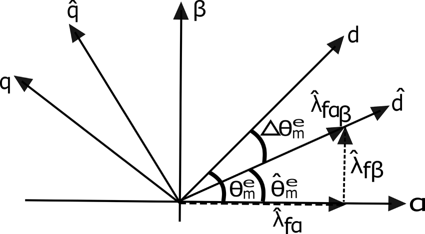
Figure 7: Vector representation of the estimated
From Fig. 7, the components of the fictitious flux in the stationary frame are
The position error signal is defined as
From Figs. 6 and 7, it is evident that when
The proposed nonlinear model is evaluated using the estimated rotor position
4.1 Stator Flux Linkage Comparison
The accuracy of the proposed estimator depends on both the magnitude and phase of the estimated flux linkage. Deviations in amplitude or phase relative to the actual flux linkage may result in erroneous speed estimation, particularly at high or low speeds. Therefore, the estimator output must remain in phase and match the magnitude of the actual flux linkage under all operating conditions. Fig. 8a–c compares the estimated and actual flux linkages under various operating conditions. It can be observed that the proposed estimator closely tracks the amplitude and phase of the actual flux linkage.
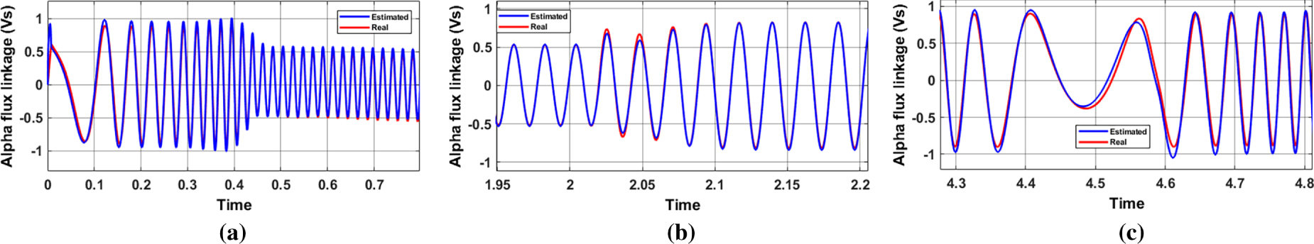
Figure 8: Comparison of estimated and actual stator flux linkage: (a) step starting; (b) step load torque; (c) reversed direction
4.2 Estimated and Actual Speed Comparison
The estimator calculates flux linkage and speed using
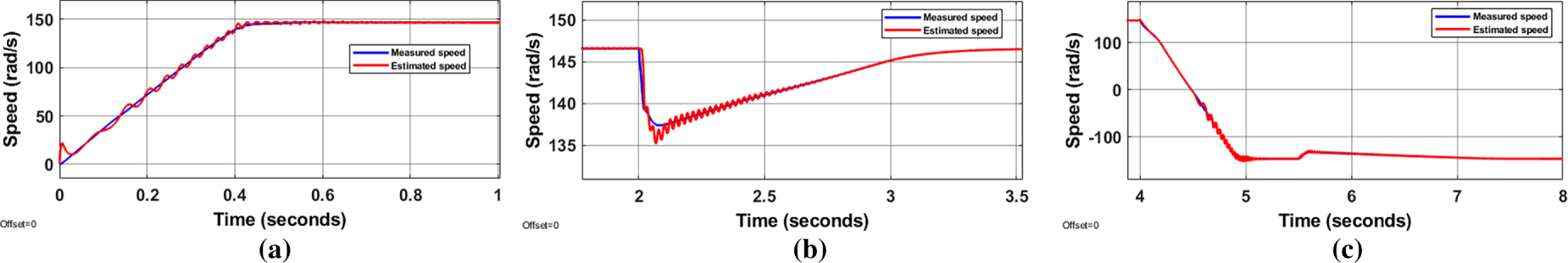
Figure 9: Comparison of estimated and actual rotor speed: (a) step starting; (b) step load torque; (c) reversed direction
4.3 Estimated and Actual Position Comparison
The estimated position is obtained by integrating the estimated speed as shown in Fig. 6. Due to initial speed estimation errors, the position contains an initial offset, as seen in Fig. 10a. Once the speed reaches approximately 20% of the rated value, the estimated position aligns with the actual position within 0.025 s. A minor deviation occurs at the speed reversal, but the estimator rapidly converges to the actual position within 0.26 s (Fig. 10a–c).
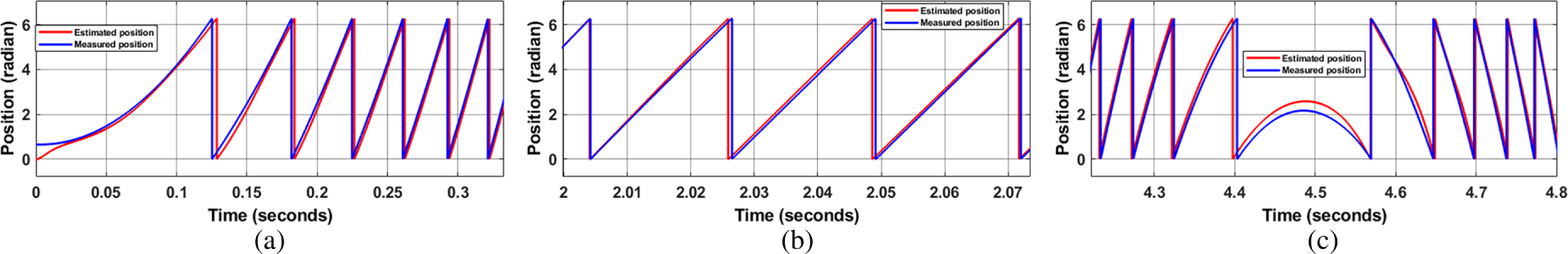
Figure 10: Comparison of estimated and actual rotor position: (a) step starting; (b) step load torque; (c) reversed direction
4.4 Estimated and Actual Electromagnetic Torque Comparison
The actual electromagnetic torque is computed using the nonlinear magnetic model (Eq. 7), while the estimated torque uses the fictitious flux linkage (Eq. 17). Fig. 11a–c demonstrates that the estimator accurately reproduces the electromagnetic torque after a brief transient.
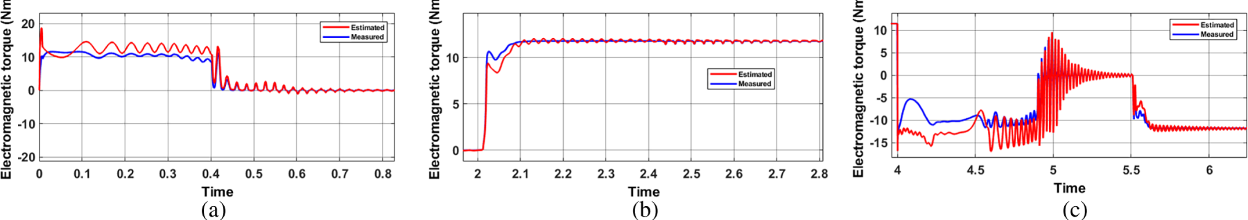
Figure 11: Comparison of estimated and actual electromagnetic torque: (a) step starting; (b) step load torque; (c) reversed direction
4.5 Estimated and Actual Currents
Figs. 12 and 13 show the estimated and actual
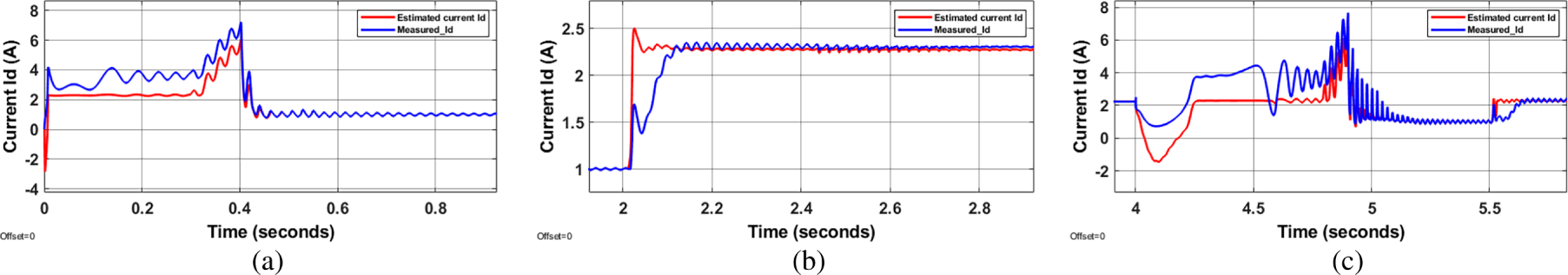
Figure 12: Comparison of estimated and actual
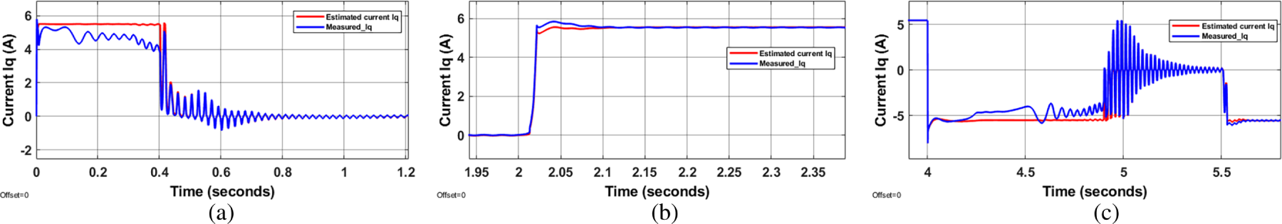
Figure 13: Comparison of estimated and actual
An advanced fictitious flux linkage approach for sensorless operation of SynRM has been presented. The main contributions and novelties of this work are:
1. A nonlinear SynRM model is used, including all effects experienced by a real machine. Unlike most studies that rely on linear
2. Two complementary methodologies, the voltage integrator and flux observer, are combined to estimate the
3. The flux observer employs a lookup table (LUT) of flux linkages across the operating range, allowing precise estimation of instantaneous
Simulation results demonstrate that the proposed model is globally stable under all operating conditions without sensors. A nonlinear magnetic model of the SynRM, verified via FEA, is used to account for rotor inductance saturation and cross-coupling effects, issues often neglected in sensorless controller design. The proposed controller overcomes these nonlinearities by using LUTs of flux linkages
Simulation comparisons confirm that the estimated rotor position
Acknowledgement: We are grateful to DANA for the funding support and all the colleagues in the Electric Drive Laboratory (EDLAB) for their invaluable support in preparation of this article.
Funding Statement: This research was funded by DANA in cordination with Ministerial Decree 117/2023-a.a. 2023/2024–XXXIX Cycle for innovative doctorates that meet the innovation needs of companies.
Author Contributions: The authors confirm contribution to the paper as follows: The conceptualization and methodology is prepared by the project supervisor Nicola Bianchi. Software validation, formal analysis and the investigation are carried by Abdin Abdin and Nicola Bianchi. Data curation and resources are mannaged by Andrea Voltan, Walter Faedo and Abdin Abdin. Original draft is prepared by Piero Cazzavillan, Alessandro Biason and Abdin Abdin. Editing and visualization are done by Piero Cazzavillan and Alessandro Biason. Project adminstrantion and funding acquistion are monitered by Andrea Voltan, Walter Faedo, Piero Cazzavillan and Alessandro Biason. All authors reviewed the results and approved the final version of the manuscript.
Availability of Data and Materials: The data that support the findings of this study are available from the Author, [Abdin Abdin], upon reasonable request.
Ethics Approval: Not applicable. This study did not involve human participants, animal experiments, or data from any individual.
Conflicts of Interest: The authors declare no conflicts of interest to report regarding the present study.
Abbreviations
| PLL | Phase locked loop |
| SynRM | Synchronous reluctance motor |
| PM | Permanent magnet |
| FEA | Finite element analysis |
| PI | Proportional Integral |
Eq. (12) can be written in terms of
where:
and
Therefore the following relation can be consider in
Joining with (A1) we get
Here
The inductance
The inductance
References
1. Ilioudis VC. A study of MTPA applied to sensorless control of the synchronous reluctance machine (SynRM). Automation. 2025;6(1):11. doi:10.3390/automation6010011. [Google Scholar] [CrossRef]
2. Pellegrino G, Jahns TM, Bianchi N, Soong WL, Cupertino F. The rediscovery of synchronous reluctance and ferrite permanent magnet motors: tutorial course notes. Cham, Switzerland: Springer International Publishing; 2016. doi:10.1007/978-3-319-32202-5. [Google Scholar] [CrossRef]
3. Murataliyev M, Degano M, di Nardo M, Bianchi N, Gerada C. Synchronous reluctance machines: a comprehensive review and technology comparison. Proc IEEE. 2022;110(3):382–99. doi:10.1109/jproc.2022.3145662. [Google Scholar] [CrossRef]
4. Heidari H, Rassõlkin A, Kallaste A, Vaimann T, Andriushchenko E, Belahcen A, et al. A review of synchronous reluctance motor-drive advancements. Sustainability. 2021;13(2):729. doi:10.3390/su13020729. [Google Scholar] [CrossRef]
5. Shilpi, Ramchand R, Lakshmi SLMP. Evolution of multi-phase synchronous reluctance motors: a comprehensive review. J Inform Syst Eng Manag. 2025;10(57s):623–43. [Google Scholar]
6. Boglietti A, Pastorelli M. Induction and synchronous reluctance motors comparison. In: Proceedings of the 2008 34th Annual Conference of IEEE Industrial Electronics; 2008 Nov 10–13; Orlando, FL, USA. p. 2041–4. doi:10.1109/IECON.2008.4758270.. [Google Scholar] [CrossRef]
7. Albassioni KBT, Ibrahim M, El-Kholy EE, Sergeant P. Construction of synchronous reluctance machines with combined star-pentagon configuration using standard three-phase stator frames. IEEE Trans Indust Elect. 2022;69(8):7582–95. doi:10.1109/tie.2021.3105997. [Google Scholar] [CrossRef]
8. Woo TG, Lee SH, Lee HJ, Yoon YD. Flux weakening control technique without look-up tables for SynRMs based on flux saturation models. Electronics. 2020;9(2):218. doi:10.3390/electronics9020218. [Google Scholar] [CrossRef]
9. Boazzo B, Vagati A, Pellegrino G, Armando E, Guglielmi P. Multipolar ferrite-assisted synchronous reluctance machines: a general design approach. IEEE Trans Indust Elect. 2015;62(2):832–45. doi:10.1109/tie.2014.2349880. [Google Scholar] [CrossRef]
10. Capolino GA, Cavagnino A. New trends in electrical machines technology—Part I. IEEE Trans Indust Elect. 2014;61(8):4281–5. doi:10.1109/tie.2013.2295770. [Google Scholar] [CrossRef]
11. Vagati A. The synchronous reluctance solution: a new alternative in AC drives. In: Proceedings of the IECON’94—20th Annual Conference of IEEE Industrial Electronics; 1994 Sep 5–9; Bologna, Italy. p. 1–13. doi:10.1109/IECON.1994.397741. [Google Scholar] [CrossRef]
12. Accetta A. Robust control of synchronous reluctance motor based on automatic disturbance rejection. IEEE Open J Ind Applicat. 2024;5:209–23. doi:10.1109/ojia.2024.3399009. [Google Scholar] [CrossRef]
13. Boztas G, Aydogmus O. Implementation of sensorless speed control of synchronous reluctance motor using extended Kalman filter. Eng Sci Technol Int J. 2022;31:101066. doi:10.1016/j.jestch.2021.09.012. [Google Scholar] [CrossRef]
14. Habyarimana M, Adebiyi AA. Selection and placement of sensors for electric motors: a review and preliminary investigation. Energies. 2025;18(13):3484. doi:10.3390/en18133484. [Google Scholar] [CrossRef]
15. Ran Y, Qiao M, Sun L, Xia Y. Review of position sensorless control technology for permanent magnet synchronous motors. Energies. 2025;18(9):2302. doi:10.3390/en18092302. [Google Scholar] [CrossRef]
16. Tuovinen T, Hinkkanen M, Harnefors L, Luomi J. A reduced-order position observer with stator-resistance adaptation for synchronous reluctance motor drives. In: Proceedings of the 14th International Power Electronics and Motion Control Conference EPE-PEMC 2010; 2010 Sep 6–8; Ohrid, Macedonia. p. T5-174T5179. doi:10.1109/EPEPEMC.2010.5606645. [Google Scholar] [CrossRef]
17. Cai H, Luo W. Full-speed sensorless control system of synchronous reluctance motor with flux saturation model. Sci Rep. 2025;15(1):9048. doi:10.1038/s41598-025-92441-7. [Google Scholar] [PubMed] [CrossRef]
18. Nikmaram B, Mousavi MS, Khalaji Z, Davari SA, Rodriguez J, Fazeli M. Sensorless control of synchronous reluctance motors based on newton-raphson iteration algorithm. In: Proceedings of the 2023 3rd International Conference on Electrical Machines and Drives (ICEMD); 2023 Dec 20–21; Tehran, Iran. p. 1–6. doi:10.1109/ICEMD60816.2023.10429587. [Google Scholar] [CrossRef]
19. Farhan A, Abdelrahem M, Hackl CM, Kennel R, Shaltout A, Saleh A. Advanced strategy of speed predictive control for nonlinear synchronous reluctance motors. Machines. 2020;8(3):44. doi:10.3390/machines8030044. [Google Scholar] [CrossRef]
20. Hackl CM. Non-identifier based adaptive control in mechatronics: theory and Application. Vol. 466. Cham, Switzerland: Springer; 2017. doi:10.1007/978-3-319-55036-7. [Google Scholar] [CrossRef]
21. Hackl CM, Kamper MJ, Kullick J, Mitchell J. Nonlinear PI current control of reluctance synchronous machines. arXiv:1512.09301. 2015. doi:10.48550/arXiv.1512.09301. [Google Scholar] [CrossRef]
22. Lagerquist R, Boldea I, Miller TJE. Sensorless-control of the synchronous reluctance motor. IEEE Trans Indust Applicat. 1994;30(3):673–82. doi:10.1109/28.293716. [Google Scholar] [CrossRef]
23. Capecchi E, Guglielmi P, Pastorelli M, Vagati A. Position sensorless control of transverse-laminated synchronous reluctance motors. In: Proceedings of the Conference Record of the 2000 IEEE Industry Applications Conference. Thirty-Fifth IAS Annual Meeting and World Conference on Industrial Applications of Electrical Energy (Cat. No.00CH37129); 2000 Oct 8–12; Rome, Italy. p. 1766–73. doi:10.1109/IAS.2000.882119. [Google Scholar] [CrossRef]
24. Koonlaboon S, Sangwongwanich S. Sensorless control of interior permanent-magnet synchronous motors based on a fictitious permanent-magnet flux model. In: Proceedings of the Fourtieth IAS Annual Meeting. Conference Record of the 2005 Industry Applications Conference; 2005 Oct 2–6; Hong Kong, China. p. 311–8. doi:10.1109/IAS.2005.1518326. [Google Scholar] [CrossRef]
25. Sangwongwanich S, Suwankawin S, Po-ngam S, Koonlaboon S. A unified speed estimation design framework for sensorless AC motor drives based on positive-real property. In: Proceedings of the 2007 Power Conversion Conference–Nagoya; 2007 Apr 2–5; Nagoya, Japan. p. 1111–8. doi:10.1109/PCCON.2007.373105. [Google Scholar] [CrossRef]
26. Boldea I, Paicu MC, Andreescu GD. Active flux concept for motion-sensorless unified AC drives. IEEE Trans Power Elect. 2008;23(5):2612–8. doi:10.1109/tpel.2008.2002394. [Google Scholar] [CrossRef]
27. Boldea I, Andreescu GD, Rossi C, Pilati A, Casadei D. Active flux based motion-sensorless vector control of DC-excited synchronous machines. In: Proceedings of the 2009 IEEE Energy Conversion Congress and Exposition; 2009 Sep 20–24; San Jose, CA, USA. p. 2496–503. doi:10.1109/ECCE.2009.5316509. [Google Scholar] [CrossRef]
28. Accetta A, Cirrincione M, Pucci M, Sferlazza A. Space-vector state dynamic model of the SynRM considering self, cross-saturation and iron losses and related identification technique. IEEE Trans Indust Applicat. 2023;59(3):3320–31. doi:10.1109/tia.2023.3252528. [Google Scholar] [CrossRef]
29. Pinyopawasutti T, Sangwongwanich S. Fictitious flux and a globally stable observer for sensorless control of synchronous reluctance motors. In: Proceedings of the 2018 International Electrical Engineering Congress (iEECON); 2018 Mar 7–9; Krabi, Thailand. p. 1–4. doi:10.1109/IEECON.2018.8712167. [Google Scholar] [CrossRef]
30. Berto M, Alberti L, Manzolini V, Bolognani S. Computation of self-sensing capabilities of synchronous machines for rotating high frequency voltage injection sensorless control. IEEE Trans Indust Elect. 2022;69(4):3324–33. doi:10.1109/tie.2021.3071710. [Google Scholar] [CrossRef]
31. Drobnič K, Gašparin L, Fišer R. Fast and accurate model of interior permanent-magnet machine for dynamic characterization. Energies. 2019;12(5):783. doi:10.3390/en12050783. [Google Scholar] [CrossRef]
32. Łyskawinski W, Jędryczka C, Stachowiak D, Łukaszewicz P, Czarnecki M. Finite element analysis and experimental verification of high reliability synchronous reluctance machine. Eksploat I Niezawodn. 2022;24(2):386–93. doi:10.17531/ein.2022.2.20. [Google Scholar] [CrossRef]
33. Li C, Wang G, Zhang G, Zhao N, Xu D. Review of parameter identification and sensorless control methods for synchronous reluctance machines. Chinese J Elect Eng. 2020;6(2):7–18. doi:10.23919/cjee.2020.000007. [Google Scholar] [CrossRef]
34. Varvolik V, Prystupa D, Buticchi G, Peresada S, Galea M, Bozhko S. Co-simulation analysis for performance prediction of synchronous reluctance drives. Electronics. 2021;10(17):2154. doi:10.3390/electronics10172154. [Google Scholar] [CrossRef]
35. Nardo MD, Calzo GL, Galea M, Gerada C. Design optimization of a high-speed synchronous reluctance machine. IEEE Trans Indust Applicat. 2018;54(1):233–43. doi:10.1109/tia.2017.2758759. [Google Scholar] [CrossRef]
36. Sizov GY, Zhang P, Ionel DM, Demerdash NAO, Rosu M. Automated bi-objective design optimization of multi-MW direct-drive PM machines using CE-FEA and differential evolution. In: Proceedings of the 2011 IEEE Energy Conversion Congress and Exposition; 2011 Sep 17–22; Phoenix, AZ, USA. p. 3672–8. doi:10.1109/ECCE.2011.6064267. [Google Scholar] [CrossRef]
37. Lee D, Kim JW, Lee CG, Jung SY. Variable mesh adaptive direct search algorithm applied for optimal design of electric machines based on FEA. IEEE Trans Magnetics. 2011;47(10):3232–5. doi:10.1109/tmag.2011.2152380. [Google Scholar] [CrossRef]
38. Khude JT, Shaikh AH, Ugale R. Comparative analysis of 5 HP SynRM And FeA-SynRM for EV applications. In: Proceedings of the 2024 International Conference on Vehicular Technology and Transportation Systems (ICVTTS); 2024 Sep 27–28; Bangalore, India. p. 1–6. doi:10.1109/ICVTTS62812.2024.10763949. [Google Scholar] [CrossRef]
39. Xu A, Li X, Hu S, Liu X. Sensorless control of permanent magnet-assisted synchronous reluctance motor based on adaptive sliding mode observer. Progress Electromag Res Letters. 2024;117:33–40. doi:10.2528/PIERL23103001. [Google Scholar] [CrossRef]
40. Murr M, Giaouris D. Universal PLL strategy for sensorless speed and position estimation of AC motor drives. IEEE Trans Indust Elect. 2009;56(8):2894–904. doi:10.1109/iciinfs.2008.4798473. [Google Scholar] [CrossRef]
Cite This Article
 Copyright © 2026 The Author(s). Published by Tech Science Press.
This work is licensed under a Creative Commons Attribution 4.0 International License , which permits unrestricted use, distribution, and reproduction in any medium, provided the original work is properly cited.
 Downloads
 Citation Tools