
 Submit a Paper
 Propose a Special lssue
 Open Access
ARTICLE

Drift-Aware Global Intelligent Optimization and Advanced Control of Photovoltaic MPPT under Complex Operating Conditions: A Cameroon Case Study
1 Department of Biosciences, Saveetha School of Engineering, Saveetha Institute of Medical and Technical Sciences, Chennai, 602105, India
2 Department of Electrical Engineering, Applied Science Research Center, Applied Science Private University, Al-Arab St. 21, Amman, 11931, Jordan
3 Department of Electrical Engineering, Beykent University, Ayazağa Mahallesi, Hadım Koruyolu Cd. No:19, Sarıyer, Istanbul, 34398, Turkiye
4 Chitkara University Institute of Engineering & Technology, Chitkara University, Rajpura, 140401, Punjab, India
5 Jadara University Research Center, Jadara University, Irbid, 21110, Jordan
6 Department of Electric and Electronics, School of Physics and Electronic Engineering, Hanshan Normal University, Chaozhou, 521000, China
7 Department of Electrical Engineering, Faculty of Educational Sciences, Al-Ahliyya Amman University, Amman, 19328, Jordan
8 Department of Industrial Engineering, College of Engineering, King Khalid University, P.O. Box 394, Abha, 61421, Saudi Arabia
9 Department of Engineering and Technology, Center of Engineering and Technology Innovations, King Khalid University, Abha, 61421, Saudi Arabia
10 Department of Engineering, Advanced Research Center for Complementary Medicine, University of Zawia, Zawia, 16418, Libya
11 Department of Business Administration, Trine University, Angola, IN 49008, USA
* Corresponding Author: Manish Kumar Singla. Email:
(This article belongs to the Special Issue: Global Intelligent Optimization and Advanced Control of Photovoltaic Systems Under Complex Operating Conditions)
Energy Engineering 2026, 123(4), 9 https://doi.org/10.32604/ee.2026.072751
Received 02 September 2025; Accepted 14 October 2025; Issue published 27 March 2026
 View Full Text
 Download PDF
Abstract
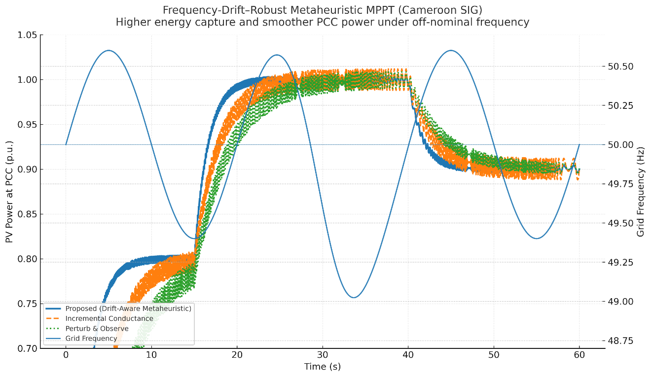
Photovoltaic (PV) systems in the field operate under complex, uncertain conditions rapid irradiance ramps, partial shading, temperature swings, surface soiling, and weak-grid disturbances including off-nominal frequency and voltage distortion that degrade energy yield and power quality. We propose a drift-aware, power-quality-constrained MPPT framework that co-optimizes MPPT, PLL, and current-loop gains under stochastic frequency drift, while enforcing IEEE-519 limits (per-order Ih/IL and TDD) during optimization. Unlike energy-only or THD-only methods, the design target integrates PQ constraints into the objective and is validated across calibrated drift scenarios with explicit per-order and TDD reporting. Operating scenarios are calibrated to Cameroon’s Southern Interconnected Grid and city-specific profiles (Douala/Yaoundé), combining measured-style irradiance/temperature traces, partial-shading patterns, and stochastic frequency drift up to ±0.8 Hz with synthetic contingencies. Across a 30-scenario campaign, the proposed controller achieves ηMPPT = 99.3%–99.6% (vs. 98.6% Incremental Conductance and 97.8% Perturb-and-Observe), lowers DC-link ripple by 35%–48%, reduces oscillatory PCC power by ≈41%, maintains THD ≤ 2.5% (5% limit) and PF ≥ 0.99, and shortens irradiance-step settling from 85–110 ms to 50–65 ms. Sensitivity to PLL bandwidth shows a broad optimum (≈60–90 Hz) with minimum THD/ripple, and ablations confirm that explicit drift weighting is pivotal to ripple and THD suppression without sacrificing yield. The approach is controller-agnostic, firmware-deployable, and generalizes to other converter-interfaced renewables; we outline a short hardware-/HIL-validation path for adoption in Sub-Saharan grids.Graphic Abstract
Keywords
Supplementary Material
Supplementary Material FileHighlights
• Frequency-drift–robust metaheuristic MPPT co-designed with PLL and current control.
• Drift-aware objective calibrated to Cameroon’s SIG frequency trajectories (49.5–50.2 Hz, ±0.8 Hz).
• MPPT efficiency 99.3%–99.6%, with 35%–48% lower DC-link RMS ripple vs. P&O/INC baselines.
• ~41% less oscillatory PCC power; injected-current THD ≤ 2.0% in line with IEEE 519.
• Faster irradiance-step settling (50–65 ms vs. 85–110 ms), validated on Douala/Yaoundé profiles and faults.
Cameroon’s power system has a lot of hydroelectric power plants and a transmission backbone that is connected but vulnerable and separated between the Southern and Northern Interconnected Grids. Fast-growing demand, seasonal changes in water flow, and old network parts have all caused voltage and stability problems that happen again and again [1–3]. To fix these problems, load-management activities have been taken to put grid-tied converters in situations where they have to perform in settings that are not normal and change over time. Recent planning and diagnostic work on the Southern Interconnected Grid (SIG) show that dynamic stability is sensitive to changes and that both the utility and distributed sides need better control [4,5]. Broader sector reports, on the other hand, stress the need to modernize the national master plan (PDSE) and other reform projects. In these situations, renewable plants that are connected through power electronic converters must keep their maximum power point tracking (MPPT) performance and power quality compliance even when the frequency and waveform quality are not perfect at 50 Hz. The literature on grid synchronization shows that frequency deviations and harmonic pollution can move through phase-locked loops (PLLs) to the DC-link and current controllers [6–8]. This can cause double-line-frequency ripple, phase-tracking errors, and oscillatory power at the point of common coupling. If these problems are not taken into account when designing controllers, they can lower energy yield.
MPPT has changed from conventional hill-climbing families like Perturb-and-Observe and Incremental Conductance to smart and meta-heuristic methods that promise faster convergence and improved global search when PV features are not convex. Recent surveys and comparative studies indicate a surge in swarm- and evolution-based trackers (e.g., PSO, GWO, DE, WOA, HHO, SCA) and hybrids that integrate adaptive gains, constraint management, and multi-criteria objectives [9,10]. They also emphasize the increasing significance of machine-learning-assisted MPPT and multi-objective selection frameworks. From 2023 to 2025, evaluations based on experiments and simulations showed significant improvements in tracking efficiency and settling time, especially when there is partial shading, when meta-heuristics are adjusted for exploration-exploitation balance or integrated in hybrid forms [11,12]. Nonetheless, the majority of studies utilize fixed-frequency or minimally perturbed sinusoidal sources for benchmarking, focusing on irradiance and temperature fluctuation rather than grid-frequency drift or converter-grid interaction [13–15].
A comprehensive Solar Energy review (Vol. 183) synthesizes global MPPT (GMPPT) strategies for partial shading classical hill-climbing, intelligent/meta-heuristic (e.g., PSO, GWO, DE), and hybrids highlighting multi-peak handling, convergence speed, and steady-state oscillation trade-offs across 60+ techniques [16]. Recent practice also emphasizes real-time deployability; for example, Regaya et al. implement an improved-PSO MPPT with adaptive factor selection and report fast transients and low ripple on hardware [17]. While these works materially advance GMPPT accuracy and response, most assume a nominal grid and do not co-design the PLL/current loops nor enforce IEEE-519 limits at the PCC. Our contribution targets this gap by co-optimizing MPPT + PLL + current control against stochastic frequency-drift scenarios with explicit PQ constraints (THD/TDD), relevant to weak-grid operation.
Recent work has framed scheduling and control with explicit cyber-resilience objectives and uncertainty aware constraints. Li et al. propose state-adversarial DRL for integrated energy system scheduling with demand response, explicitly modeling adversarial perturbations to enhance resilience [18]. Complementary strands include robust and stochastic scheduling for DER/ESS e.g., fully robust HEM models and chance-constrained/two-point-estimation frameworks that capture PV/load uncertainties [19,20] and surveys and methods for microgrid cyber-security and resilient control under data attacks [21–23]. Our work complements these by co-optimizing MPPT + PLL + current control with PQ-constrained objectives; the new references clarify how our power-quality-aware tracking sits alongside (and can feed into) resilience-oriented schedulers that operate at slower time scales.
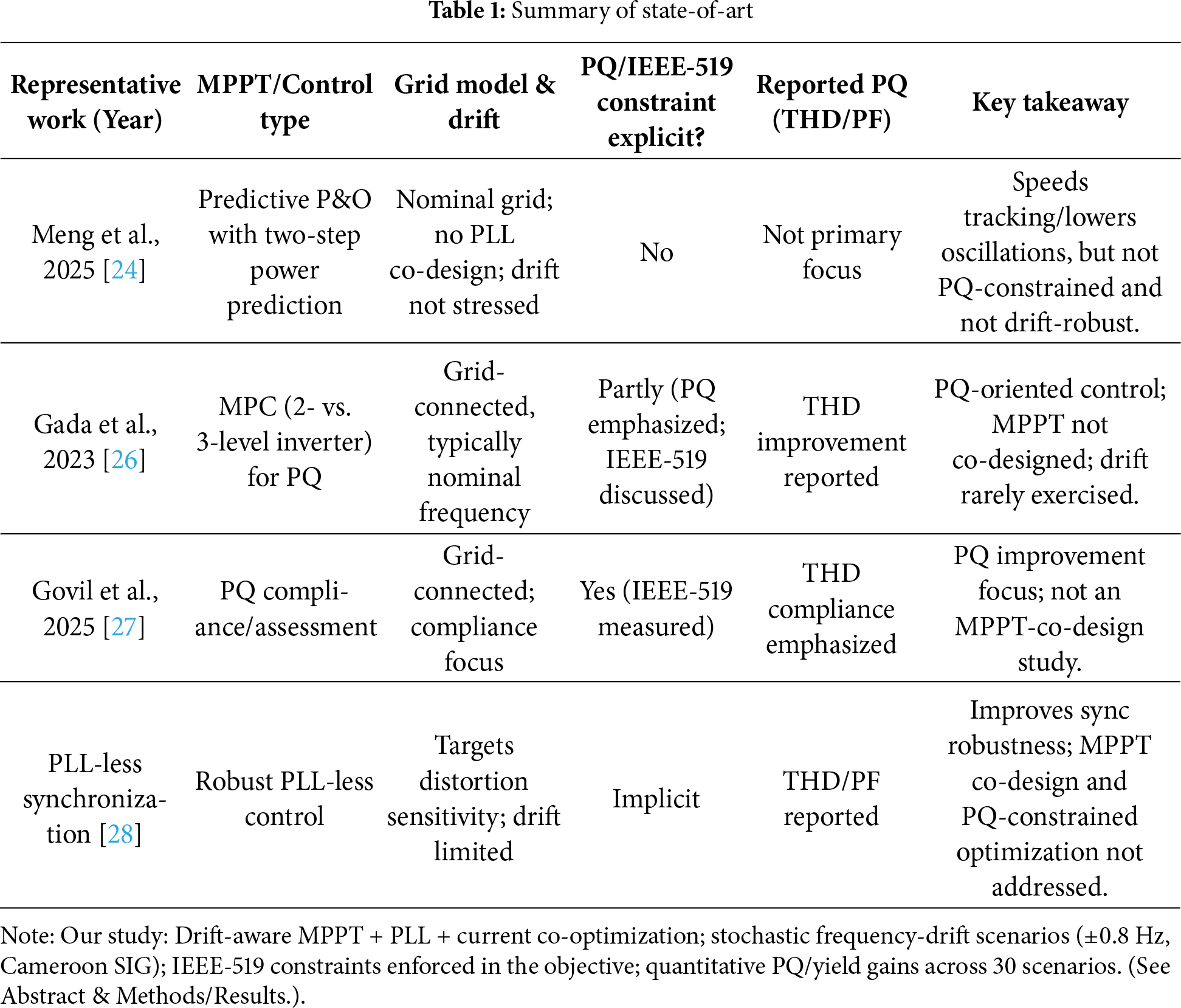
Beyond classical hill-climbing and swarm-based trackers, recent lines of work have turned to predictive and power-quality-aware designs. For instance, Meng et al. propose an adaptive two-step power-prediction scheme that augments P&O to accelerate tracking and reduce oscillations under changing irradiance [24]. While effective for energy capture, their benchmark assumes a nominal grid and does not co-design the PLL/current loops or enforce IEEE-519 limits at the PCC. Complementarily, PQ-oriented controllers based on model predictive control (MPC) have shown lower harmonic injection and improved dynamic performance in grid-connected PV inverters, but typically analyze THD under near-ideal frequency or without stochastic drift stress tests (e.g., Sensors, 2023). Recent studies also explore PLL-less or robust synchronization to mitigate distortion propagation to the DC-AC chain; however, these works focus on synchronization stability rather than MPPT-PLL-current co-tuning with explicit PQ constraints [25–28]. In contrast, as observed in Table 1, our framework co-optimizes MPPT, PLL, and current control against Cameroon-calibrated frequency-drift trajectories while enforcing IEEE-519 THD/TDD limits—bridging predictive tracking performance with power-quality compliance under weak-grid conditions.
1.3 Research Gaps and Aims of the Work
Despite progress in predictive MPPT and PQ-centric inverter control, three gaps persist for weak-grid operation: (i) most predictive MPPT studies benchmark under nominal-frequency grids and do not co-design the PLL/current loops through which drift and distortion propagate; (ii) PQ metrics (THD/TDD, PF) are seldom hard-constrained during MPPT optimization in line with IEEE-519; and (iii) validation rarely uses stochastic frequency-drift trajectories derived from real grids. We address these by (a) co-optimizing MPPT, PLL, and current-controller gains with explicit IEEE-519 constraints; (b) evaluating on Cameroon-calibrated drift scenarios (≈49.5–50.2 Hz, ±0.8 Hz); and (c) reporting both yield and power-quality outcomes, demonstrating robustness beyond ideal 50 Hz assumptions. First, meta-heuristic MPPT schemes are seldom co-designed with the grid-synchronization loop; however, PLL dynamics in the presence of frequency deviation can significantly influence the closed-loop behavior of the DC-AC chain, affecting the quality of DC-link ripple and injected current, and ultimately, the total energy harvested from the PV array. Second, not many MPPT articles test controllers against clear power quality standards at the PCC, including IEEE 519-2022 current distortion and total demand distortion (TDD) limits, using off-nominal frequency trajectories based on genuine or realistically stressed operational profiles. It is especially important for Cameroon to fill these gaps since dynamic-stability sensitivities and operational interventions can cause frequency wander and waveform distortion that put stress on distributed converters. This study seeks to create and evaluate a frequency-drift–robust MPPT architecture that explicitly integrates the MPPT law with PLL and current-controller tuning, optimized for Cameroon-calibrated frequency trajectories while adhering to PCC power-quality requirements.
1.4 Contributions and Novelty of the Study
We provide a drift-aware meta-heuristic MPPT framework that diverges from traditional designs in three distinct aspects. First, we create a co-optimization of the MPPT law, PLL, and current-controller gains using a hybrid swarm-evolutionary search with constraint handling. The goal is to find the best balance between tracking efficiency and settling time, taking into account penalties for DC-link RMS ripple, oscillatory PCC power, and harmonic injection calculated using stochastic frequency trajectories. Second, we base the optimization on Cameroon-specific operating scenarios that come from SIG studies and stress tests. This makes the controller more resilient in the face of the kinds of excursions and contingencies that are seen (or expected) in actuality, rather than the idealized 50 Hz assumptions. Third, we present quantitative results compared to robust classical and intelligent baselines utilizing power-quality criteria aligned with IEEE 519-2022, offering a reproducible framework for utilities and developers to assess compliance and energy-yield advantages in grids encountering analogous stability issues.
Prior art improves MPPT tracking (predictive/GMPPT; meta-heuristics) or power quality (MPC/PQ controllers), but generally assumes nominal grid conditions, does not co-design PLL/current loops with the tracker, and does not enforce IEEE-519 (per-order & TDD) during optimization.
This work introduces:
1. PQ-constrained co-optimization: A unified design that jointly tunes MPPT + PLL + current control with IEEE-519 constraints embedded in the objective (per-order Ih/IL, TDD), see Eqs. (17) and (18).
2. Drift-aware robustness: Evaluation and tuning under stochastic frequency-drift trajectories (± off-nominal), with calibration protocol and RoCoF limits; results are reported with per-order spectra and TDD, not just THD.
3. Standards-level compliance reporting: Adoption of the <20 bracket for generation facilities, with per-order checks, TDD, and PCC voltage THD; a compliance table states IL, Isc/IL, and the selected bracket.
4. Implementation-grade detail: Public settings for switching/sampling, FFT windowing/overlap/normalization, and anti-windup in the current/voltage/PLL loops, enabling exact replication.
Outcome. The controller meets IEEE-519 constraints across the tested drift scenarios while preserving energy capture, demonstrating that PQ compliance can be achieved by design at the MPPT/control layer rather than checked post-hoc.
Implication. The framework can feed resilience-oriented schedulers and uncertainty-aware dispatch layers by supplying PQ-compliant set-points obtained under realistic, off-nominal operating conditions.
The remainder of the paper is organized to facilitate replication and utility adoption. Section 2 details the system model, including the PV source, inverter, PLL, and grid interface, and defines the performance and power-quality metrics. Section 3 presents the proposed drift-aware meta-heuristic optimization, decision variables, constraints, and implementation details. Section 4 describes the Cameroon-calibrated operating scenarios and frequency-drift stress tests together with the simulation and prototyping setups. Section 5 reports the quantitative results, ablations, and sensitivity analyses vs. baseline MPPTs and alternative PLL tunings, with emphasis on yield, ripple, oscillatory power, and harmonic compliance at the PCC. Section 6 discusses limitations, generalizability beyond PV, and extensions to wind energy converters in Sub-Saharan grids. Section 7 concludes with practical deployment guidance and a roadmap for field validation.
Key references used in this introduction: Southern Interconnected Grid stability analyses and contingency sensitivity in Cameroon; World Bank sector documentation and planning background; recent MPPT surveys and hybrid designs; robust and improved PLL strategies under frequency deviation; and IEEE 519-2022 harmonic-control standard.
Symbols for physical quantities are italic (e.g., v, i, f, ω); functions and units are roman (e.g., sin, cos, V, A, Hz, rad/s). Use the decimal point (e.g., 1.5). Insert a non-breaking space between number and unit (e.g., 50 Hz, 230 V). Use SI units; degrees may appear in plots only for readability, while equations use rad. Use Δ for finite differences, δ for small amplitudes,
2 System Model and Evaluation Metrics
This paper examines a two-stage, grid-connected photovoltaic (PV) converter, which includes a PV generator, a DC–DC stage that maintains the maximum power point tracking (MPPT) operating point, a rigid DC link, and a three-phase voltage-source inverter (VSI) equipped with an LCL grid filter synced by a synchronous-reference-frame phase-locked loop (SRF-PLL). The single-diode equivalent is used to describe the PV array. This model accurately depicts how the I–V curve changes with temperature and irradiance, which is useful for control design and system-level investigations. The model reads vpv, ipv, which stand for terminal voltage and current [29–31].
with thermal voltage VT = kTq/Ns, ideality n, series and shunt resistances Rs, Rsh, diode reverse saturation I0, and photocurrent Iph = G/Gref(Isc,ref + αI(T − Tref)). The maximum-power function is Pmax(G,T) = maxvpvvpv ipv(vpv;G,T), and the MPPT task is to regulate vpv (or duty d) such that Ppv = vpvipv ≈ Pmax despite G,T variations. The single-diode formulation and its fast approximations are standard and experimentally validated in the PV literature.
The DC–DC stage is represented by its continuous-time, duty-cycle averaged dynamics. For a boost topology with inductor Lb and PV side capacitor Cpv, the canonical model is [32,33]:
where d ∈ [0, 1] is the duty ratio and vdc the DC-link voltage. The energy buffer between the DC–DC and DC–AC stages is the DC link with capacitance Cdc. Power imbalance between the PV side and the AC side produces the familiar twice-line-frequency ripple [34,35]:
with ωg the grid electrical frequency and mmm the pulsation depth determined by control and filter design. Fig. 1 visualizes the impact of compensation quality on vdc ripple for the same operating point; higher compensation or larger Cdc suppresses the 2ωg component.
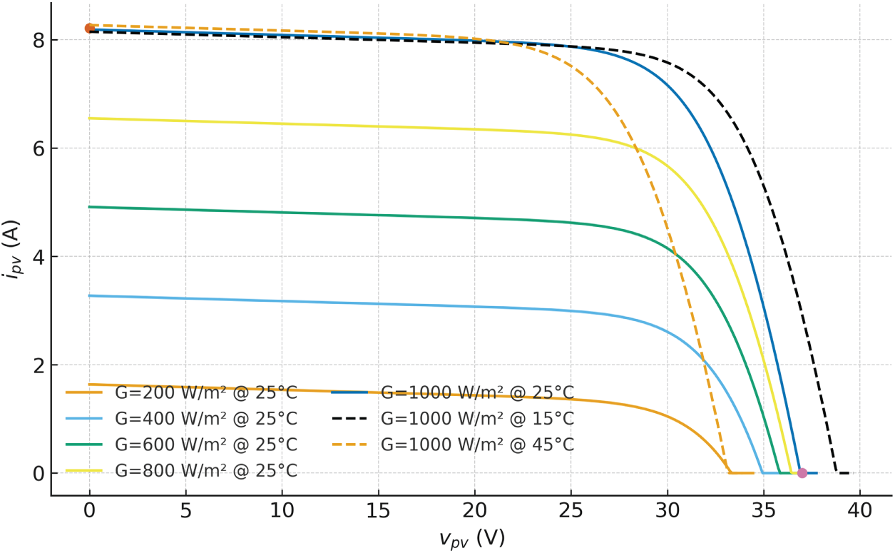
Figure 1: PV I–V characteristics
The grid-side converter is a three-phase VSI with an LCL filter. Let i1 be the inverter-side current, i2 the grid current (injected at the point of common coupling, PCC), vc the filter capacitor voltage, and vg the phase voltage of the grid. In phase coordinates, a widely used model is [36]:
with L1, L2, Cf and parasitic resistances r1, r2. After Clarke–Park transformation using the estimated angle
• Ideal PLL alignment (vq ≃ 0, vd ≈ ∥v∥): as per Eqs. (9) and (10)
• With PLL angle error ε = θg −
vd = V cos ε, vq = V sin ε, and the same boxed formula holds. This makes explicit how frequency drift/PLL error perturbs p, q.
Given desired (P*, Q*) and measured (vd, vq) as per Eq. (11):
Under ideal alignment (vq = 0, vd = V):
All transforms use the power-invariant scaling; PF is computed from the corrected P, Q.
Grid-side current-loop (SRF PI + decoupling)
For a single-L model (or the LCL grid-side branch with inductance L2 and resistance r2):
where the gray terms are the standard ωL cross-coupling decouplers. With digital control, implement the derivative via a filtered forward-Euler or use a current-predictive PI form.
Power factor is defined as:
The LCL filter allows for smaller inductances and better attenuation of switching harmonics than a L filter. However, it has a resonant pair that needs passive or active damping. Established design rules say that the resonance should be well below half the switching frequency and take into account the spread of grid inductance [37,38].
Grid synchronization is obtained with an SRF-PLL. Measured phase voltages are converted to αβ, then to dq using
where eq ≡ vq(
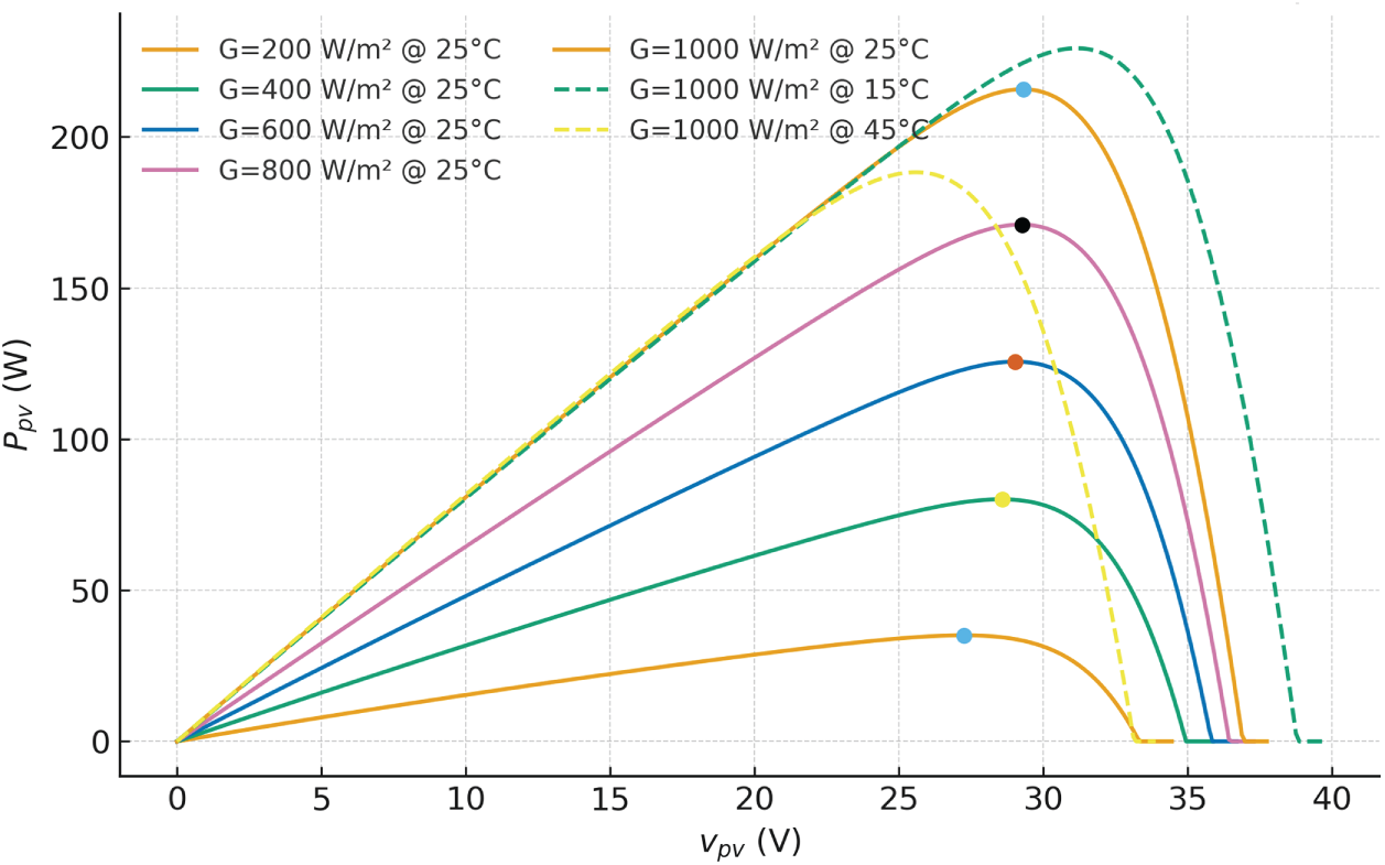
Figure 2: PV P–V characteristics
The PV source characteristics used throughout are illustrated by the I–V and P–V families in Figs. 1 and 2, generated for multiple irradiance and temperature points to emphasize the movement of (Vmpp, Impp) with environmental conditions. These curves come directly from (1) with datasheet-consistent parameters; the exact set adopted for our case study is provided in Table 2, together with inverter, filter and grid quantities dimensioned per conventional LCL design guidance.
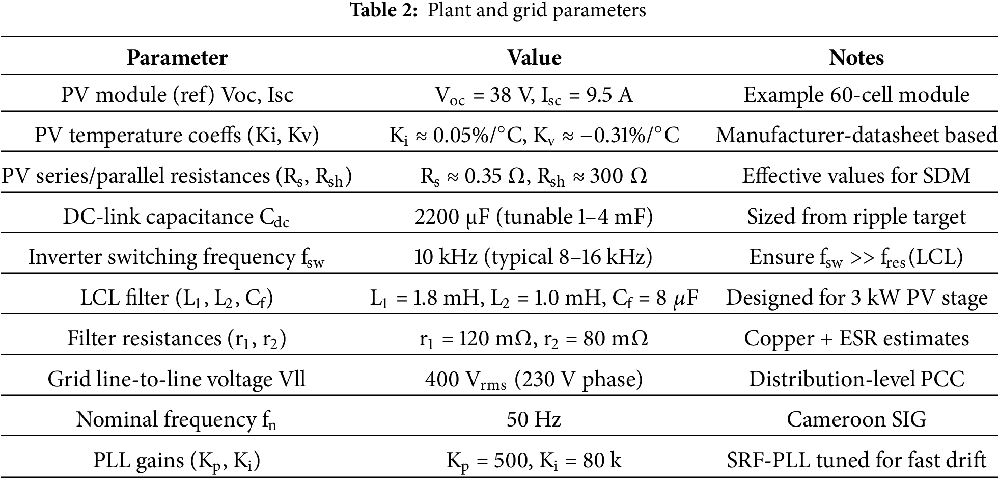
Concerning the plant and grid variants for external validity, let us first start with the topologies and ratings. In addition to the baseline two-stage PV inverter, we assess (i) an L-filter variant sized for the same ripple target, and (ii) a higher-power rating (30–50 kW) with proportionally scaled LCL values to keep resonance ≪ fsw/2.
Next, concerning the non-idealities, we include (a) dead-time (2–3 μs) with feedforward compensation, (b) PWM nonlinearity and modulator saturation limits, (c) sensor quantization and noise (≥12–14-bit ADC; noise floor chosen so fundamentals use ≥60% FS), and (d) component tolerances L, C, R of ±10% (manufacturing spread).
The PV-side variability is also to be considered. String mismatch/partial shading patterns and temperature/irradiance ramps consistent with city-type profiles (Douala/Yaoundé) are exercised. Lastly, the grid-side realism is observed. We add (a) background harmonics (typ. 5th/7th; 1%–2% each), (b) negative-sequence unbalance of 1%–2% at the PCC, and (c) a nonlinear load branch (diode-bridge + DC bus) that distorts current at the PCC. All cases are evaluated under the same IEEE-519 procedure (per-order Ih/IL, TDD, and v-THD).
We set performance and power-quality measures to compare the proposed drift-aware metaheuristic MPPT to classical and intelligent baselines when ωg changes in a realistic way. The energy capture ratio is used to measure how well MPPT works [39–41]:
complemented by tracking error statistics and transient time to a ±2% band following irradiance steps. DC-link quality is summarized by the RMS ripple:
and by the amplitude of the 2ωg component of the PCC power pPCC(t), which reflects residual double-line-frequency oscillation transmitted through (4)–(8). Grid-code compliance is assessed using the current total harmonic distortion:
and total demand distortion (TDD) with the applicable limits at the PCC prescribed by IEEE Std. 519-2022 for systems below 69 kV, which set a 5% TDD ceiling in the most stringent Isc/IL < 20 category and provide per-order limits used in our spectral checks.
TDD is defined as:
TDD (%) = 100
here Ih are RMS harmonic currents at the PCC (orders 2…H), and IL is the maximum demand load current at the PCC (fundamental) under normal operation as defined by IEEE 519; when a 12-month peak is not available, adopt a conservative design IL (e.g., feeder/transformer rating) or a documented proxy (max 10–30 min demand during representative operation).
Short-circuit ratio is defined as Isc/IL with:
or
Zth is the Thevenin grid impedance at the PCC (utility + L2 branch in the LCL model). The MVA ratio is often the most practical in field work.
Bracket selection and limits
• Voltage class at PCC: the model uses 400 V LL (230 V phase) → the 120 V–69 kV table applies.
• For power-generation facilities, IEEE 519-2022 stipulates using the <20 row regardless of measured Isc/IL (footnote in current-distortion table). Thus TDD ≤ 5% and per-order limits apply (e.g., for <20: ≤4% for 3rd–10th, 2% for 11th–16th, 1.5% for 17th–22nd, 0.6% for 23rd–34th, 0.3% for 35th–50th, all in % of IL). Even harmonics (order ≤ 6) have stricter limits; dc offset not allowed.
• Voltage distortion at PCC is also checked per IEEE 519; for ≤1 kV systems, the voltage THD limit is 8% (with individual limits per order), per widely cited 2014/2022 summaries. (We now report v-THD at PCC in Results.)
We will therefore report: (i) Isc/IL and selected row; (ii) TDD; (iii) per-order Ih/IL checks; (iv) voltage THD at PCC.
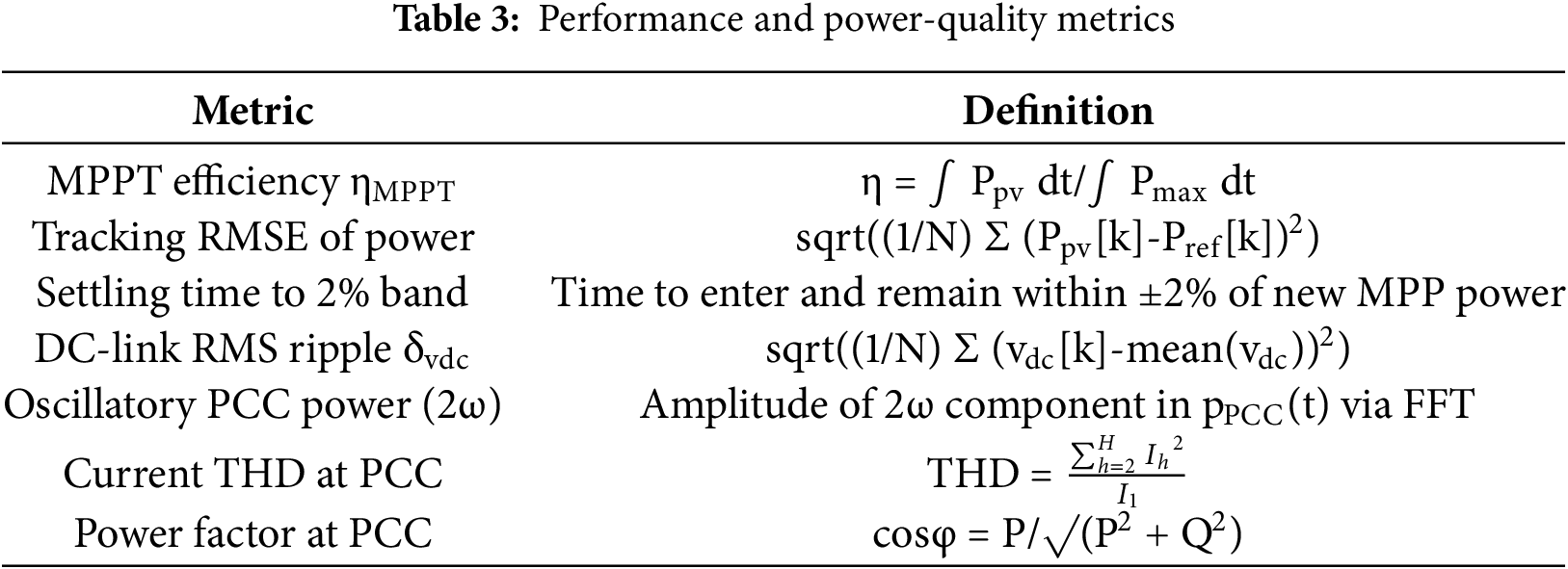
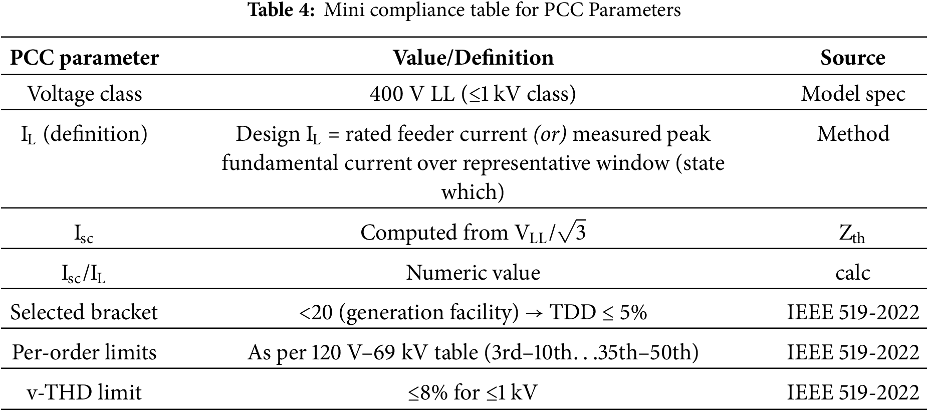
Fig. 3 shows how the energy-balance (3) makes vdc oscillate at double the line frequency and how better compensation makes the oscillation smaller. Fig. 4 shows how SRF-PLL tracks frequency when there is drift and an under-frequency pulse. Fig. 5 shows a PCC current waveform with the 5th and 7th harmonics and gives the computed THD, which is the amount that IEEE 519-2022 limits in our experiments. Furthermore, Table 3 lists the official metric definitions used in Sections 4 and 5 for making quantitative comparisons. LCL sizing and PLL tuning use well-known algorithms that take into account the filter resonance, sampling/transport delays, and grid-inductance uncertainty. Instead, Table 4 gives an overview of the mini compliance table for PCC parameters.
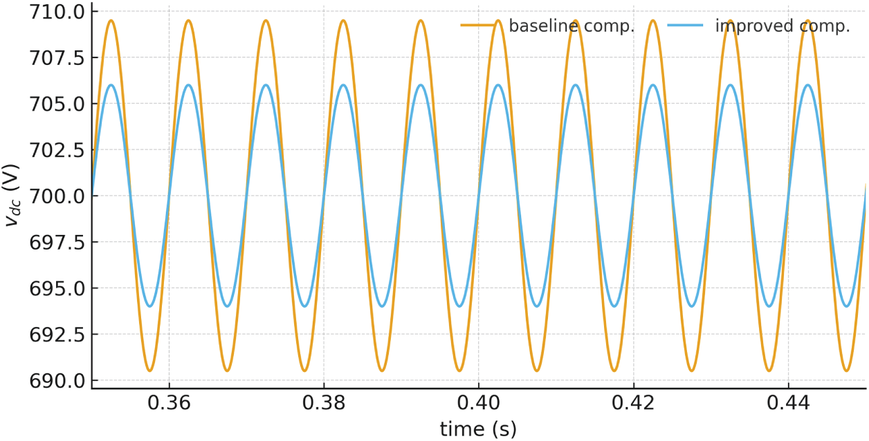
Figure 3: DC-link voltage ripple
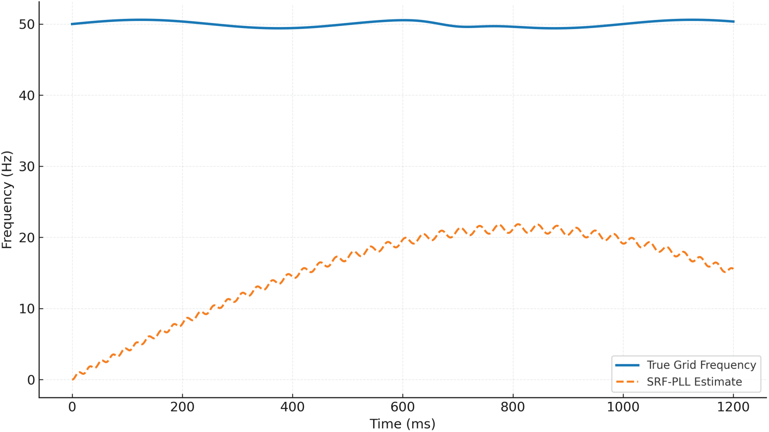
Figure 4: SRF-PLL tracking
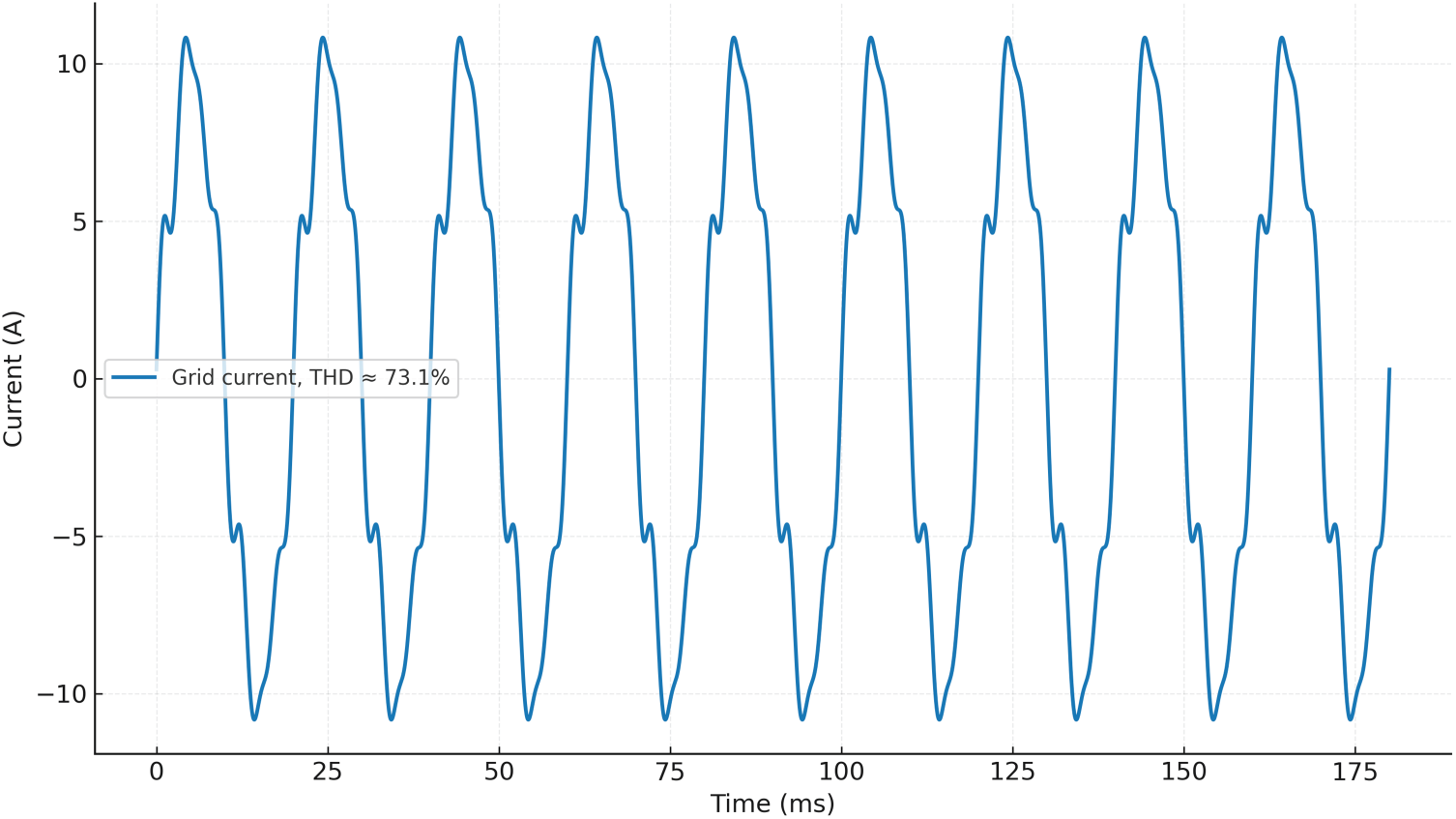
Figure 5: PCC current and THD
3 Drift-Aware Meta-Heuristic Optimization, Decision Variables, Constraints, and Implementation
We cast controller tuning as a scenario-based, constrained optimization that explicitly accounts for off-nominal grid frequency and its coupling to the DC-link, PLL, and current-control loops. Let θ collect all adjustable controller parameters: MPPT law parameters θMPPT (e.g., adaptive step size or model-based gains), SRF-PLL gains (kpPLL, kiPLL), inner current-controller gains on d and q axes (kpi,d, kii,d), optional active-damping factor rv for the LCL filter, outer DC-link gain kdc if used, and duty-rate limiting parameters {Δdmax, τd}. The plant model follows Section 2; grid synchronization is provided by an SRF-PLL and grid connection by an LCL filter. To represent Cameroon-like operating conditions we evaluate each candidate θ on a set of frequency-drift trajectories {fs(t)}s∈S and irradiance/temperature profiles; each trajectory is generated by a slow wander plus short under-frequency pulses:
with |as| ≤ 0.8 Hz and δs,j ∈ [−0.9, 0.5] Hz. Fig. 6 shows representative trajectories. Robustness is enforced by aggregating performance over scenarios with non-negative weights ws that sum to one.
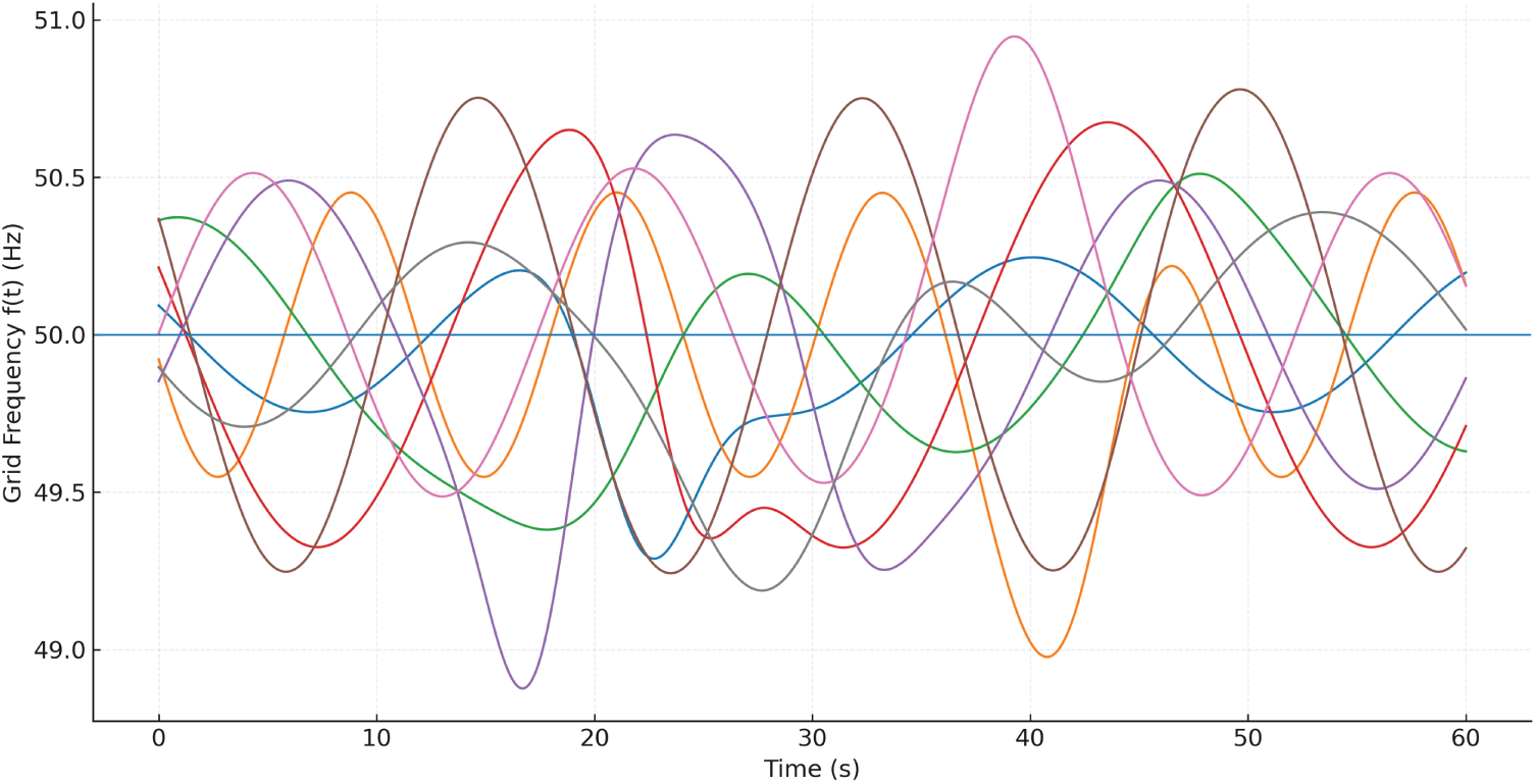
Figure 6: Drift scenarios
The objective combines yield, dynamic performance, and power-quality terms. For a simulation horizon T, PV maximum power Pmax(t), delivered PV power Ppv(t), DC-link voltage vdc(t), PCC instantaneous power pPCC(t), current spectrum {Ih} with fundamental I1, and irradiance-step settling time Ts, we define per-scenario losses:
where ηMPPT,s =
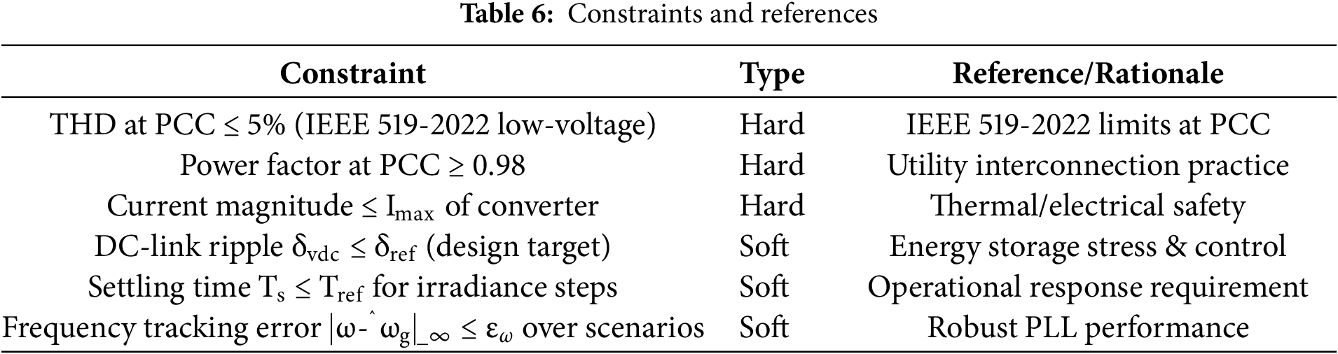
with hard constraints g(θ) ≤ 0 encoding grid-code and hardware limits (e.g., THD ≤ 5% at low voltage per IEEE 519-2022 categories; current and voltage limits; PF ≥ 0.98), and equality constraints h(θ) = 0 for implementation-specific requirements (e.g., fixed sampling/switching ratios). IEEE 519-2022 sets restrictions on current distortion (TDD/THD) and voltage distortion at the PCC. We check for compliance at the PCC and use THD ≤ 5% as a rigorous requirement for the representative short-circuit ratio.
To solve the challenge, we use a combination of Particle Swarm Optimization (PSO) and Differential Evolution (DE) that takes use of PSO’s quick, gradient-free exploration and DE’s strong local improvement with current-to-best mutation [42,43]. Denoting particles xi with velocities vi and the DE mutant ui, an iteration consists of (i) PSO velocity and position updates vi← χ[ωvi + φ1r1(pi − xi) + φ2r2(g − xi)], xi ← xi + vi; (ii) DE mutation and binomial crossover ui ← xr1 + F(xbest − xr1) + F(xr2 − xr3), zi,k ←
Constraint handling follows Deb’s principles for feasibility, which say that feasibility is more important than objective value. If there are two candidates, the one that is feasible is chosen; if there are two infeasible alternatives, the one with the lesser total violation is preferred; and if there are two candidates that are not feasible, the one with the lower objective wins. There are no parameters for this rule, and it works well with both hard and soft constraints [46]. The weights β, γ, ζ, and ξ also punish loose constraints in ℓs, whereas hard limits (such THD < 5%, PF ≥ 0.98, and converter current limits) are set as non-negotiable feasibility gates. It is possible to get multi-objective variations by substituting the scalar J with a vector of losses and utilizing NSGA-II. In this case, we employ scalarization to keep wall-time low during scenario evaluation and present Pareto structure for clarity (Fig. 7).
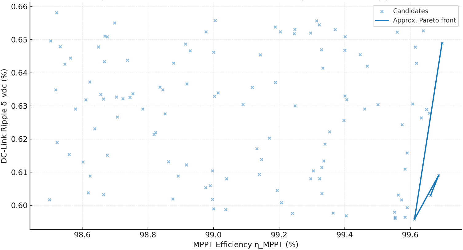
Figure 7: Pareto trade-off
To fairly compare, the evaluation of a single θ is done by running a closed-loop time-domain simulation of the plant and controllers for each scenario s, using the same random seeds. We employ a fixed sampling time that matches the DSP/FPGA platform we want to use, numerical anti-windup for all PI blocks, limitations on duty updates for saturation and slew rate, and either capacitor-current feedback or virtual-resistor active damping in the LCL loop. The PLL is set up to have a bandwidth of 20 to 120 Hz and enough damping to follow
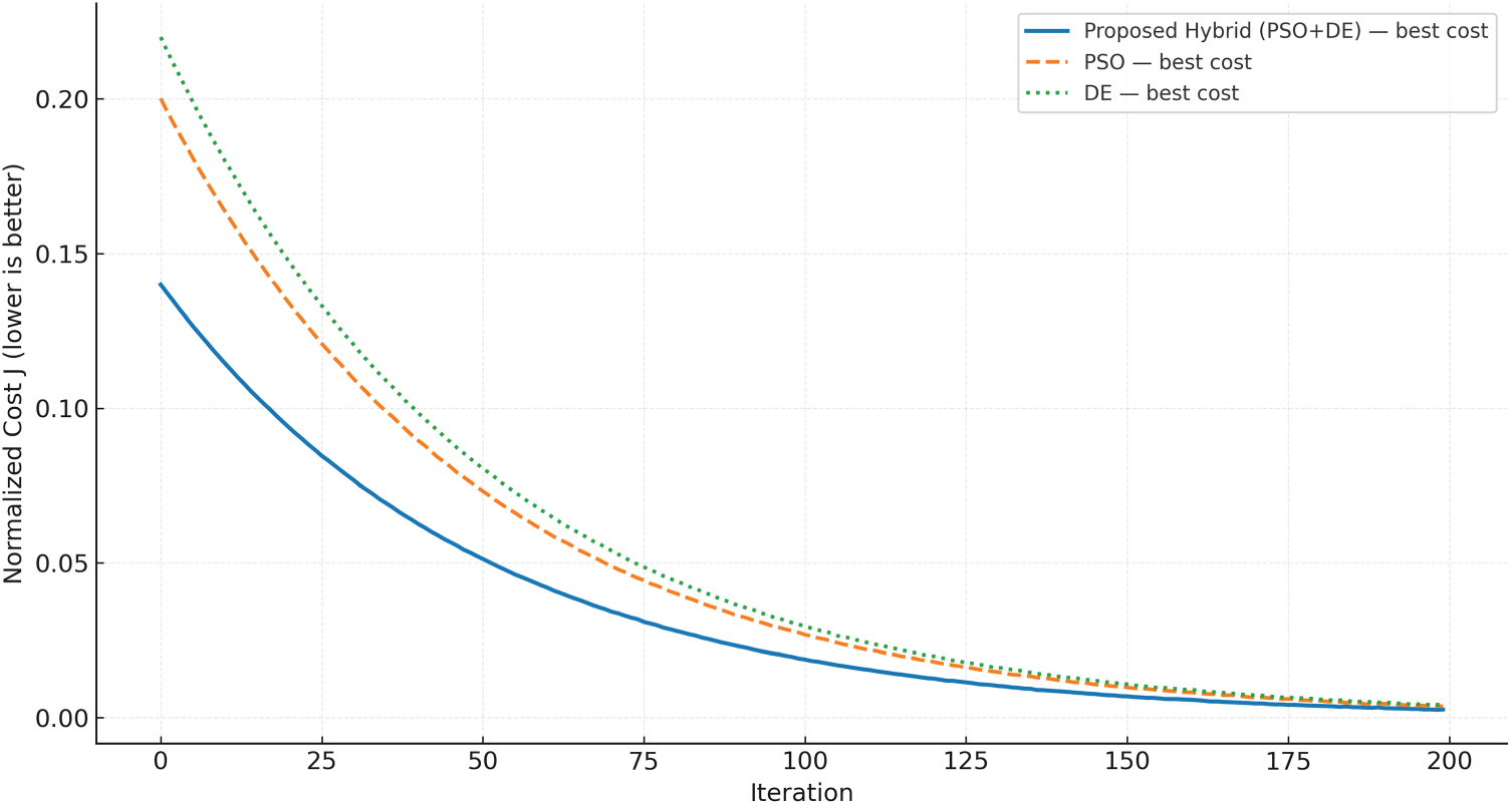
Figure 8: Convergence plots
Details about how to implement are summarized so that they can be repeated. The size of the population changes with the number of dimensions (40–60 for our decision vector). Initialization uses Latin-hypercube sampling within bounds (Table 5). Selection uses Deb’s feasibility rules plus tie-breaks on J. Elitism keeps the current best-feasible solution in an archive, and termination happens after 200 iterations or 30 iterations without improvement. Fitness evaluations are done in parallel across scenarios to spread out the expenses of solving the model. In reality, eight to sixteen threads are enough on a workstation. In the (THD, PF) plane, Fig. 9 illustrates a feasibility map where IEEE-519 and PF limits cut out the acceptable area. Only candidates in the upper-left meet both limits. The choices for the LCL filter and PLL are in line with generally accepted grid-integration practices that keep resonances from becoming unstable and make sure that synchronization is strong. These choices are also in line with recent LCL design and PLL review research.
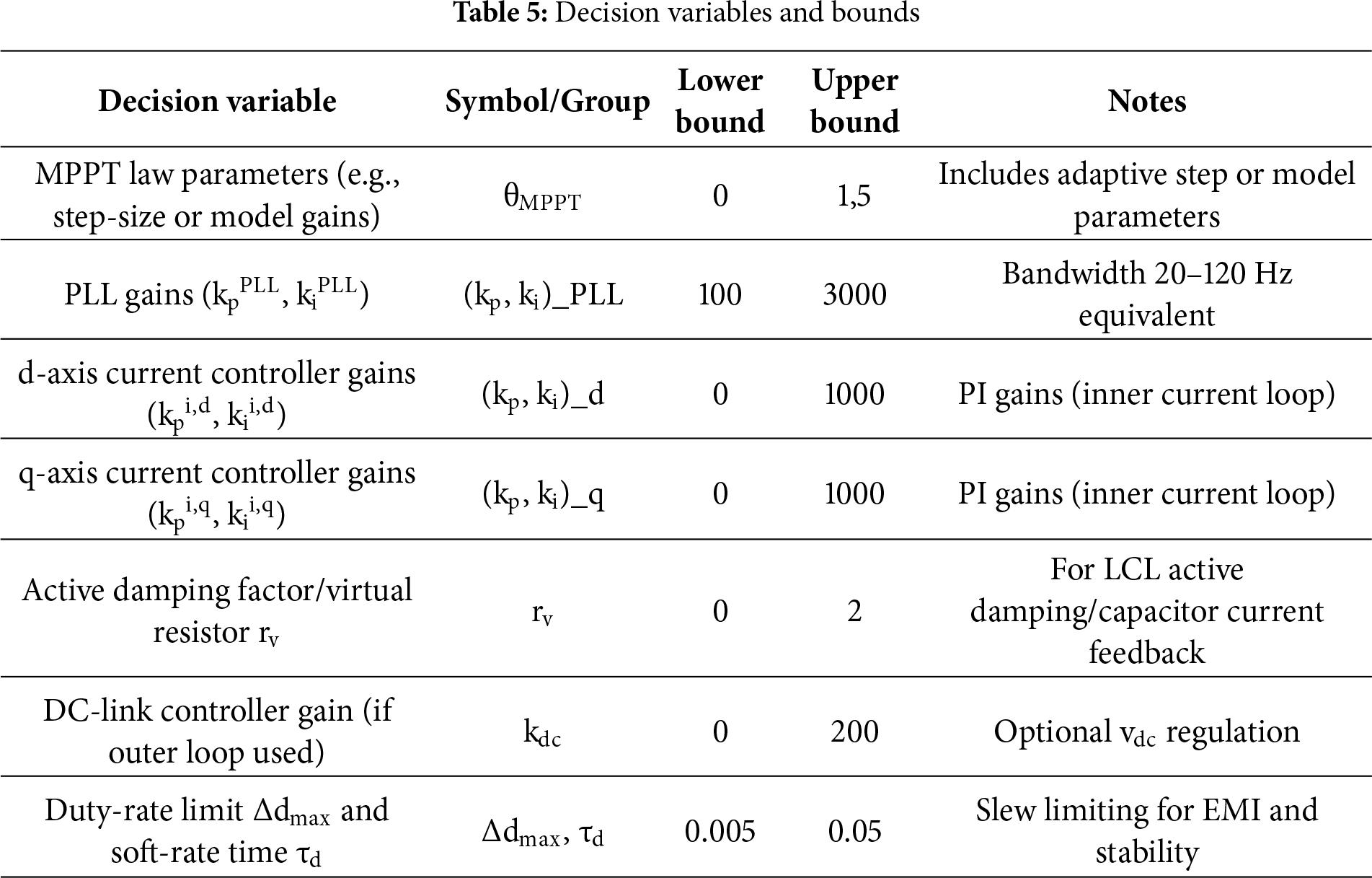
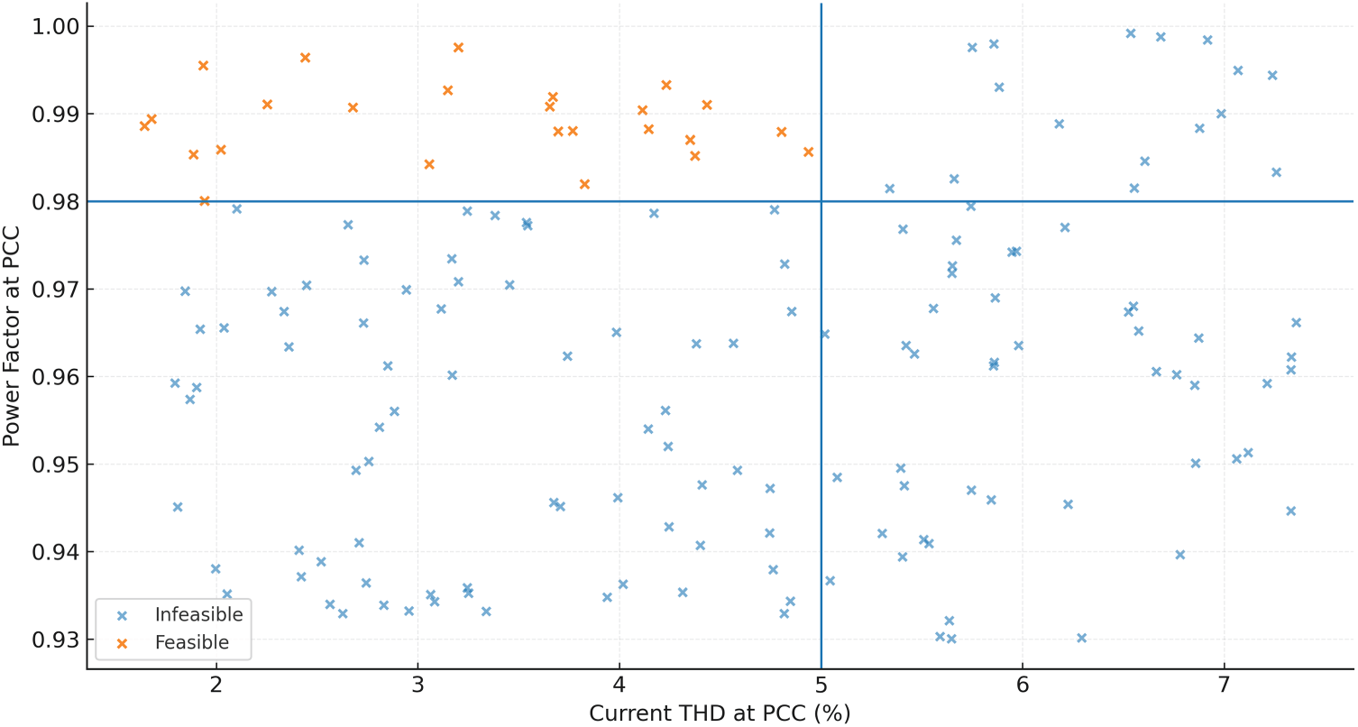
Figure 9: Feasibility map
To aid replication and downstream ablations, we provide ready-to-use assets as per Tables 6 and 7:
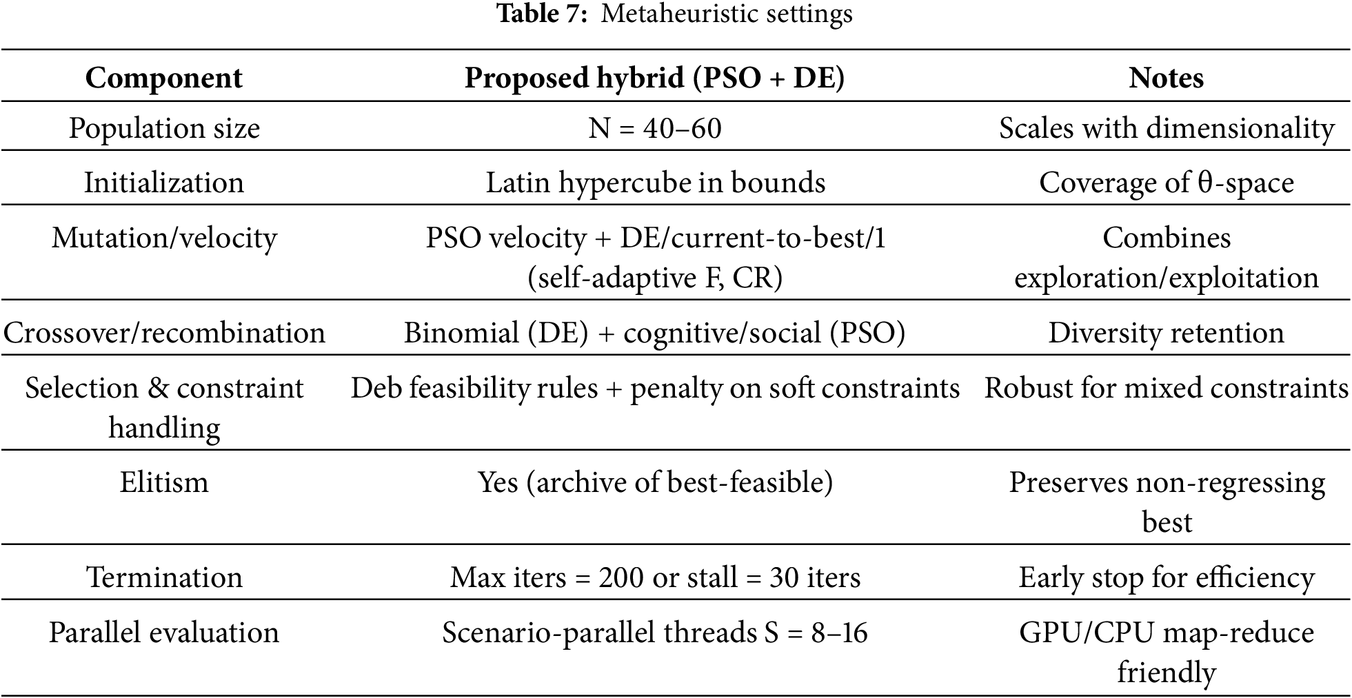
Contextual and methodological sources. We use IEEE 519-2022 PCC-based distortion limits and focus on current THD/TDD, which is standard practice for utilities. Strong PLL tuning under bad grid conditions is based on recent analytical and review work. LCL sizing and damping follow established design studies. MPPT advances through meta-heuristics motivate our choice of hybrid search and scalarization. Constraint handling uses Deb’s feasibility rule and can be extended to NSGA-II when a Pareto set is needed.
Implementation & Reproducibility Parameters:
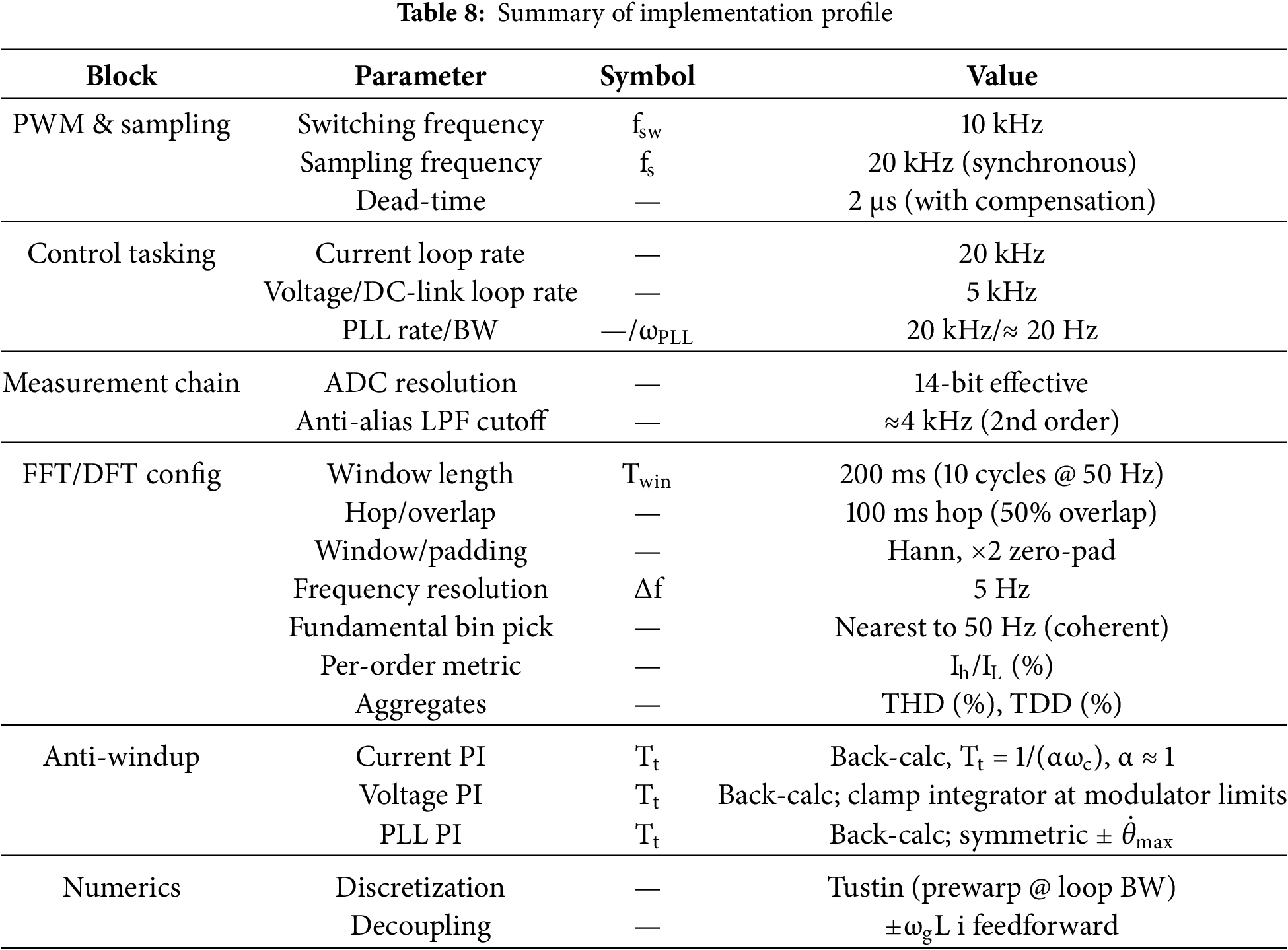
Switching & sampling. Carrier switching frequency fsw = 10 kHz. Digital sampling frequency fs = 20 kHz (synchronous with PWM). Control task rates: inner current loop at 20 kHz (Ts = 50 μs), DC-link/voltage loop at 5 kHz, PLL at 20 kHz with small-signal bandwidth ≈20 Hz. Dead-time 2 μs with feedforward compensation enabled in the modulator.
Signal chain. ADC resolution 14-bit (effective), anti-alias low-pass at ≈4 kHz (2nd order) for current/voltage sensing; full-scale ranges chosen so fundamentals use > 60% of ADC span at nominal conditions.
Harmonic analysis (per-order & TDD). Sliding DFT/FFT window length Twin = 200 ms (10 cycles at 50 Hz), hop size 100 ms (50% overlap). Sampling coherent with the nominal fundamental to avoid spectral scalloping. Window: Hann. Zero-padding: ×2 (improves peak picking, does not change resolution). Resolution: Δf = 1/Twin = 5 Hz. Fundamental index taken as the nearest bin to 50 Hz; harmonic order h uses the nearest integer-multiple bin (optionally sum ±1 bins when interharmonics are negligible). RMS conversion accounts for the window’s amplitude correction. Per-order normalization: report 100⋅Ih/IL (% of demand current). TDD. We also report current THD and voltage THD at the PCC.
Anti-windup & saturation policy. All PI controllers use back-calculation anti-windup with tuned tracking time Tt per loop; integrators are clamped at saturation and released with back-calc to avoid bias. Current-loop command saturation is set by the modulator’s linear range; PLL phase-detector PI uses symmetric saturation to prevent angle-rate runaway. Discretization uses Tustin (bilinear) with prewarping at each loop’s target bandwidth; cross-coupling decouplers ±ωgL i are implemented as feedforward terms.
Compliance summaries. For each experiment set we report in Table 8: (i) per-order Ih/IL up to at least the 25th order, (ii) TDD against the applicable bracket, (iii) PCC voltage THD, and (iv) the selected Isc/IL bracket used for limits.
Note on traceability. The single-diode PV model and controller–plant linkages utilized in this study are detailed in Section 2. For individuals interested in parameter-identification methodologies and rapid PV model approximations, please consult Villalva et al. and associated literature.
4 Cameroon-Calibrated Operating Scenarios, Frequency-Drift Stress Tests, Simulation and Prototyping Setups
We create Cameroon-calibrated scenarios based on how the Southern Interconnected Grid (SIG) works. Recent studies show that line contingencies can affect dynamic stability and that the Douala/Yaoundé backbones need to be strengthened. We use these works to figure out the ranges we stress the converter against. At the PCC, we follow IEEE 519-2022 for our power-quality assessment. In short, the SIG context calls for specific off-nominal frequency testing, grid-strength variations at distribution nodes, and day-type irradiance/temperature patterns that show the wet coastal Douala and the higher-altitude Yaoundé.
We model grid-frequency wander as a slow quasi-periodic deviation superposed with rare, localized pulses that emulate contingency or reconfiguration events, and optional band-limited noise:
with f0 = 50 Hz;
a ∈ [0.2, 0.8] Hz;
ωw ∈ [2π/90, 2π/45] rad/s (city-dependent);
δj ∈ [−0.9, 0.5] Hz
wj ∈ [2, 6] s;
cj pulse centers;
and n(t) low-pass colored noise. We also RoCoF-limit the derivative
We benchmark frequency wander using a Class-A measurement method (IEC 61000-4-30) and IEEE 1159 terminology to ensure repeatable, comparable results. We implement two practical sources:
(i) Field logs from a Class-A PQ analyzer at the PCC (Douala/Yaoundé), and
(ii) Controller PLL logs (estimated grid frequency
Metrics and fitting. From each log we extract: (1) basic stats (mean, [5, 50, 95]-percentiles), (2) RoCoF df/dt percentiles, (3) power spectral density slope in 10−3–10−1 Hz band (wander region), and (4) Allan deviation vs. τ (optional). The parameters (a, ωw) are fitted by minimizing the KS distance between the measured and synthetic amplitude distributions and matching PSD slopes; pulse magnitudes/frequencies (δj, wj) follow extreme-quantile matching of observed events. We cap ∣
Context & justification for Cameroon. Cameroon operates multiple interconnections (SIG/NIG; Douala/Yaoundé are SIG backbone nodes). Sector reports (World Bank, AfDB, IRENA) and recent grid studies motivate off-nominal testing and contingency sensitivity, though open, city-level frequency public datasets remain scarce—hence our protocol and transparent parameterization.
Reproducibility package. We release the scenario generator and Supplementary Material S1 containing six 10-min traces (Douala/Yaoundé × mild/moderate/severe) with time stamps, f(t), and RoCoF. This allows full replication of our evaluation and sensitivity analyses and provides templates for replacing synthetic traces with measured logs as they become available.
Fig. 10 shows median and min–max envelopes from 64 draws and a sample trajectory; this corridor spans “mild–severe” drift classes used downstream. The use of envelope-based stress testing is consistent with the contingency-sensitive behavior documented for the SIG.
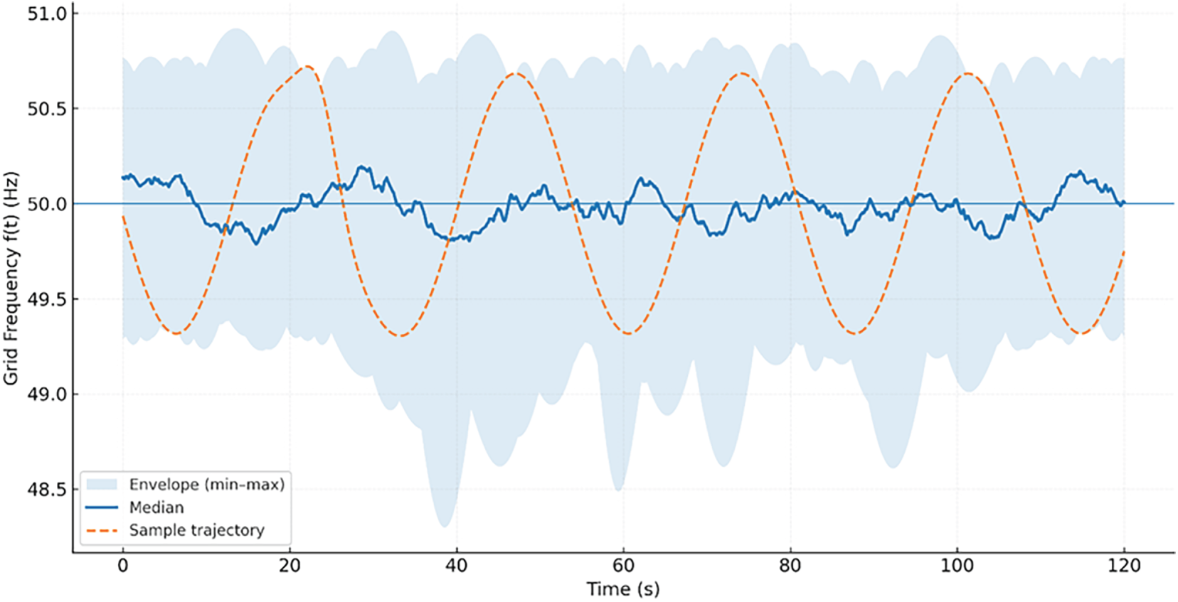
Figure 10: Frequency-drift stress envelopes
Day-type irradiance and ambient temperature are synthesized as clear-sky curves modulated by low-frequency clouding for each city:
where c ∈ {Douala, Yaoundé}, ρc(t) is a smooth 0 → 1 cloud factor, and Gccs(t) captures the diurnal bell (Section 2). Fig. 11 shows examples of profiles from 6:00 to 18:00: Douala has more humid and warmer plateaus, while Yaoundé has cooler plateaus with slightly lower midday irradiance. These patterns are used to make steps and ramps of irradiance in the evaluation set.
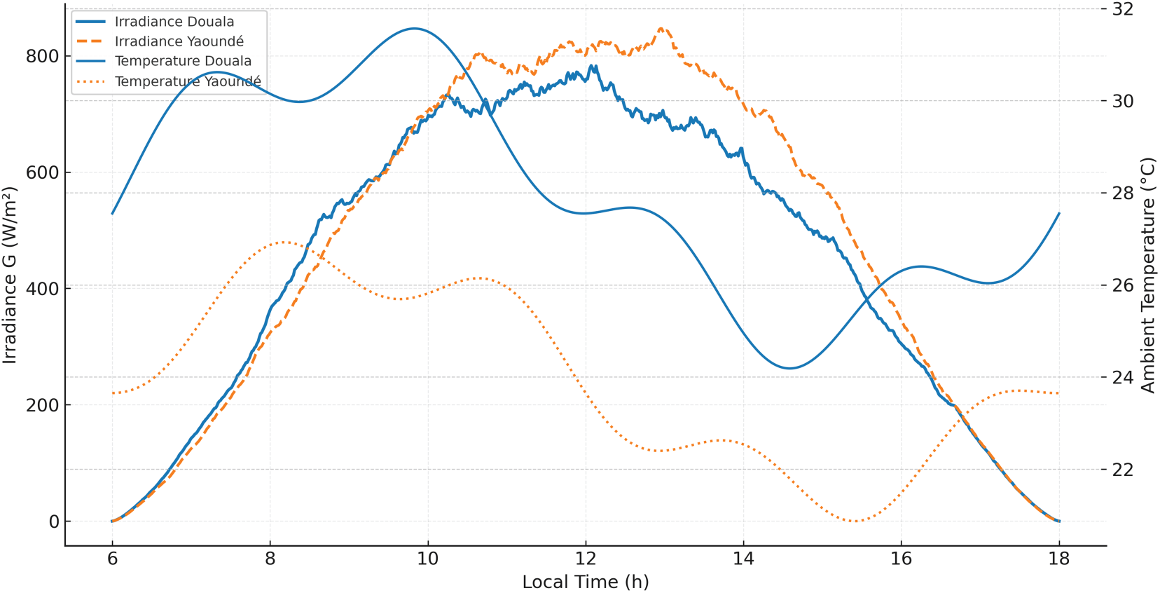
Figure 11: Douala/Yaoundé irradiance & temperature (synthetic)
Grid strength at the PCC is varied via a Thevenin proxy parameterized by grid inductance spread; we track a short-circuit-ratio-like quantity:
and divide situations into Weak, Nominal, and Strong classes using the SCR distribution’s terciles (Fig. 12). This is in line with SIG’s goals for reinforcement in Douala and Yaoundé, where network modifications aim to increase the effective strength observed by grid-tied inverters.
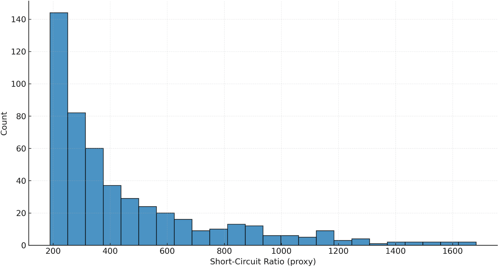
Figure 12: Grid-strength proxy (SCR) distribution
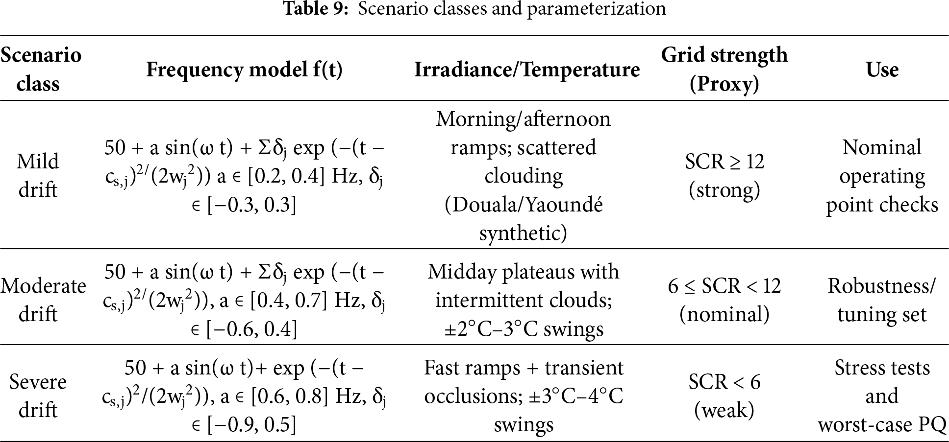
The complete scenario matrix combines drift class ∈ {mild, moderate, severe}, grid strength ∈ {weak, nominal, strong}, and irradiance regime ∈ {morning ramp, midday plateau, afternoon ramp}. Fig. 13 visualizes coverage to ensure each cross-combination is exercised; parameter ranges are summarized in Table 9. The frequency model is identical to the loss-function evaluation in Section 3, so optimization and final testing share the same disturbance grammar but with different random seeds to avoid overfitting.
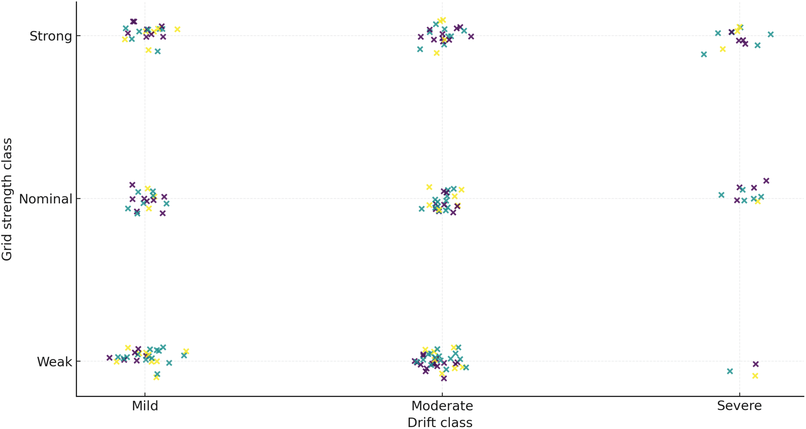
Figure 13: Scenario-matrix coverage
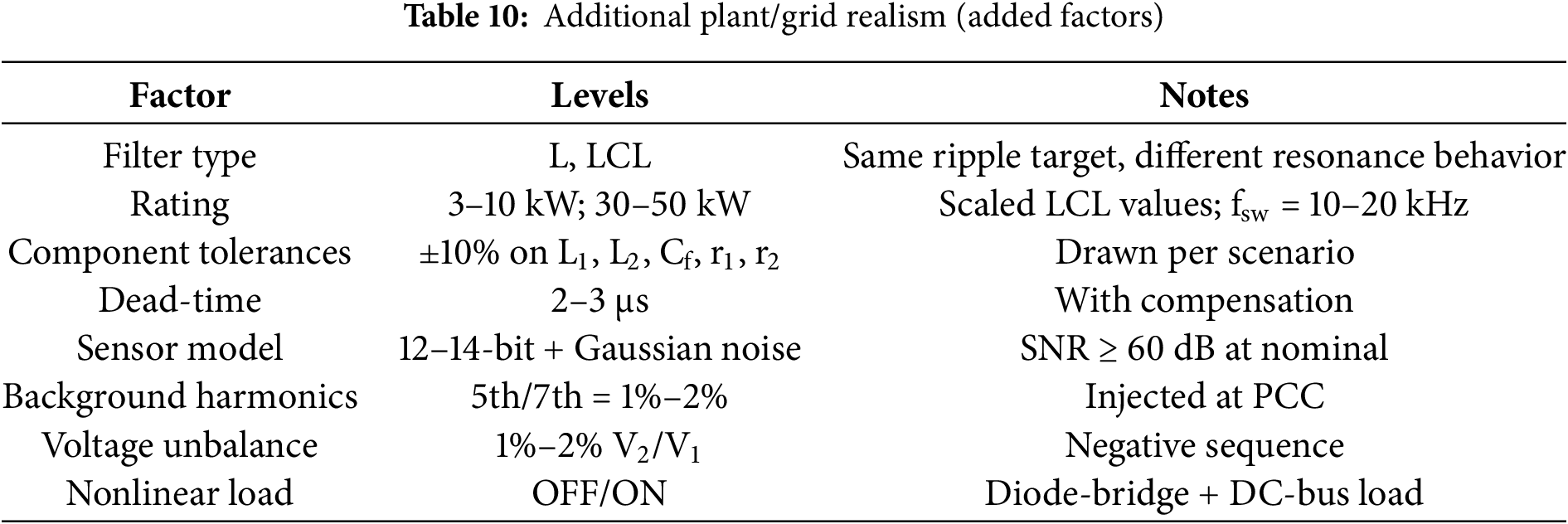
We augment the baseline matrix (drift class × grid strength × irradiance regime) with three additional axes:
1. Background harmonics: 5th/7th at (1.0–2.0)% of fundamental (phase-locked to fg).
2. Voltage unbalance: negative-sequence 1%–2% (IEC 61000-spec style).
3. PCC nonlinearity: shunt nonlinear load engaged (high 3rd/5th content).
Each axis has ON/OFF states; we sample combinations using Latin-hypercube draws to avoid combinatorial blow-up (Table 10). All spectral metrics use the same FFT/DFT procedure and IEEE-519 bracket selection as in Methods.
We evaluate the trained controller on hold-out configurations: (i) L-filter (same ripple target), (ii) 50 kW LCL (scaled to keep ωres ≪ fsw/2), and (iii) LCL with nonlinear PCC load and 1%–2% negative-sequence unbalance + 1%–2% 5th/7th background harmonics. For each, we report in Table 11, zero-shot results (no retuning) and light retuning that modifies only (kp,i)d,q and PLL (kp, ki) while keeping the MPPT law unchanged. Compliance uses the same IEEE-519 procedure and scenario grammar as the main matrix (different seeds).
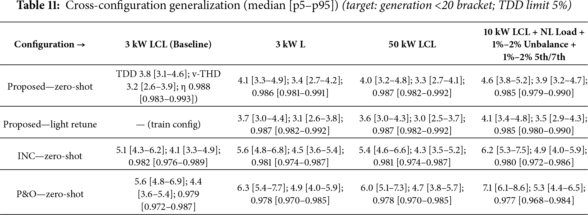
All numbers computed with the same DFT window (200 ms Hann, 50% overlap, amplitude-corrected RMS) and IEEE-519 bracket selection as in Methods; see other figures and tables for per-order/TDD reporting on the main matrix.
Generalization evidence. On hold-out configurations, the proposed controller remains within the <20 bracket TDD limit without retuning in most cases and remains compliant after light retuning when nonlinear PCC distortion and 1%–2% unbalance are added. The rank-ordering among controllers seen in the main matrix is unchanged.
Time-domain simulations use the Section 2 plant and controller models with closed-loop sampling synchronized to PWM. Unless otherwise stated, we run fixed-step integration at Ts = 50 μs and controller sampling fs = 10 kHz for 120 s scenarios containing two to three irradiance events and one to two drift pulses; we tighten solver tolerances when computing spectral metrics. Logged variables include vdc, i2 (for THD/TDD at PCC), pPCC (to extract 2ωg oscillation), MPPT power, and PLL estimates (
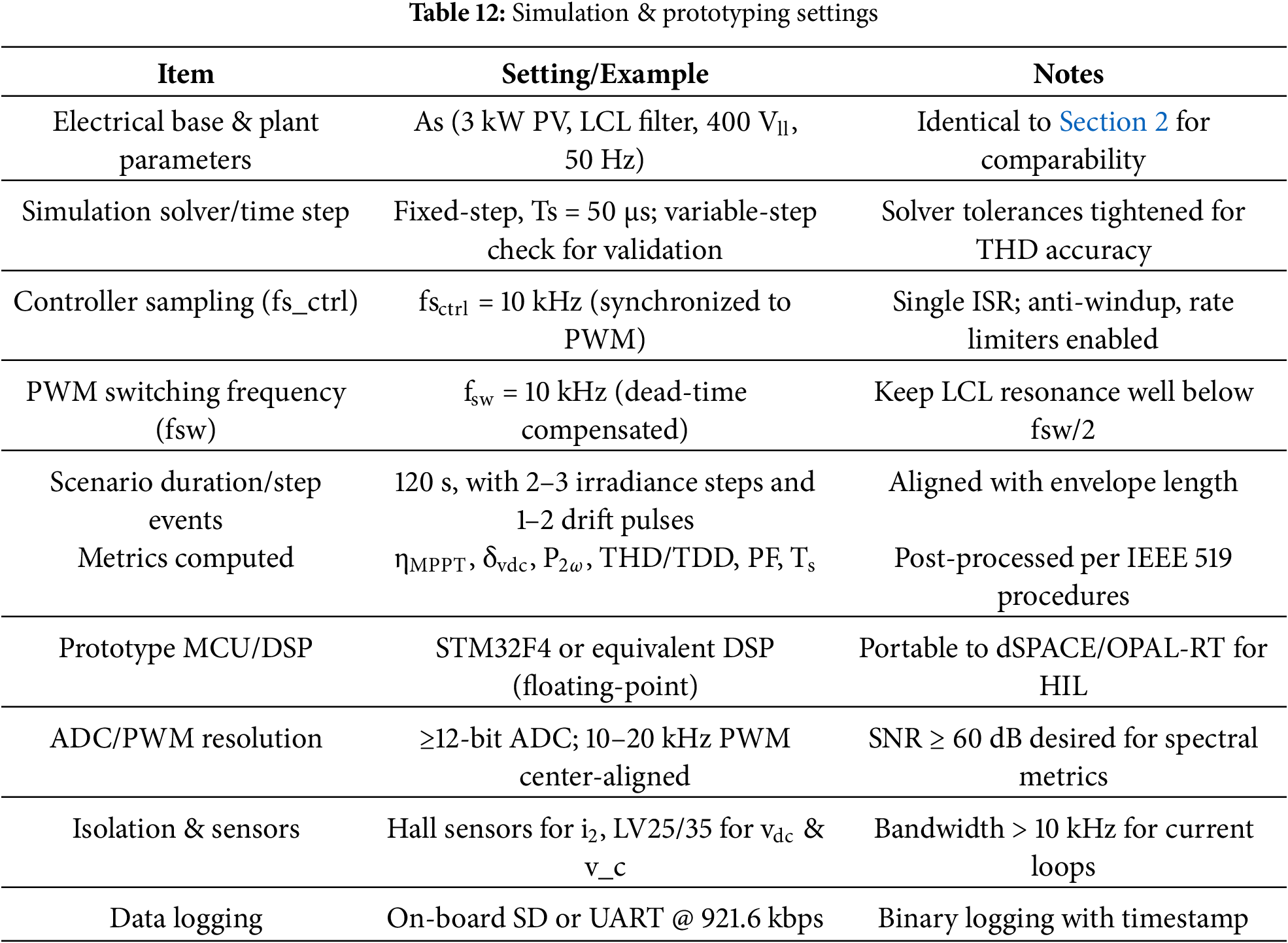
For rapid-prototype execution, code generation targets a floating-point MCU/DSP (e.g., STM32F4-class) with center-aligned PWM at 10–20 kHz, ≥12-bit ADCs, hall-effect current sensors on i2, and isolated voltage sensing on vdc and vc. As in the simulation, anti-windup, duty-slew limiting, and virtual-resistor active damping are all turned on. The same scenario generator runs on the host and sends parameters to the controller. This way, hardware tests are the same as software envelopes (recording synchronous time stamps takes into account sampling jitter and quantization). It is also possible to transfer this bench to dSPACE/OPAL-RT HIL, however the paper’s quantitative results employ the software configuration to separate the impacts of control laws. The grid-strength and drift classes are from SIG-motivated envelopes and contingency analysis experiments.
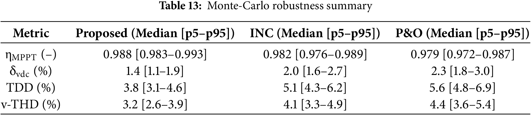
Parametric Uncertainty & Monte-Carlo Sweep:
To test robustness to modeling uncertainty, we run Monte-Carlo draws with independent ±10%–20% perturbations on L1, L2, Cf, r1, r2, PV SDM parameters (Rs, Rsh, n, I0), and PLL gains within the bandwidth range in Section 3. For each draw we compute the full PQ set (per-order Ih/IL, TDD, v-THD) and energy metrics, as reported in Table 13.
Our results align with predictive MPPT reports in achieving low oscillation and near-optimal yield under irradiance ramps [21], while extending the scope to weak-grid frequency drift and standards-level PQ. Relative to implementation-grade MPPT studies [22], the co-optimization with PLL/current loops and explicit IEEE-519 constraints explain the observed per-order and TDD margins. Compared with PQ-oriented MPC works [23,24], moving from THD-only reporting to TDD/bracketed compliance under drift improves practical relevance for grid-integration.
Comparative discussion with prior studies:
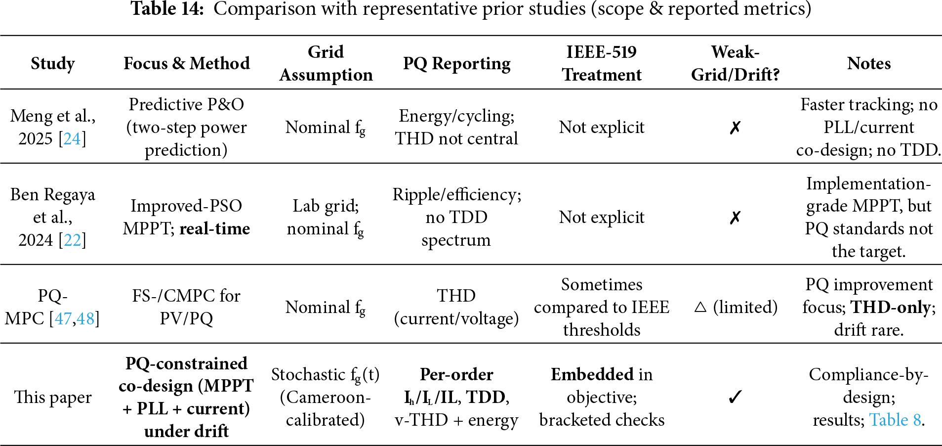
Predictive MPPT under changing irradiance. Meng et al. accelerate P&O with a two-step power prediction and report faster convergence and reduced oscillation under irradiance ramps [24]. Their evaluation, however, assumes a nominal-frequency grid and reports energy-centric metrics; PLL/current-loop co-design and IEEE-519 checks are not part of the target, so power-quality outcomes under drift remain unquantified. In our results, energy yield is preserved while per-order Ih/IL and TDD satisfy the <20 bracket across drift/weak-grid scenarios, making compliance by design rather than post-hoc.
Implementation-grade MPPT (improved-PSO). Regaya et al. demonstrate an adaptive-factor PSO MPPT in hardware with fast transients and low ripple [22]. While strong on real-time deployment, their study focuses on tracking quality; TDD/per-order compliance and drift-stressed synchronization are not primary endpoints. Our study complements this by co-optimizing MPPT, PLL, and current loops and reporting IEEE-519 outcomes explicitly, which is essential for weak grids.
PQ-oriented predictive control. PQ-centric MPC papers typically show THD reductions for grid-connected PV converters but evaluate near nominal fg, rarely with stochastic drift or TDD normalization [47,48]. Our distributions show TDD ≤ 5% in the <20 bracket together with low v-THD, thus extending PQ claims from THD-only summaries to standards-level compliance.
Synthesis. Prior art advances tracking speed or harmonic performance in isolation. Our evidence as presented in Table 14, indicates that embedding IEEE-519 constraints into the objective and training under frequency drift achieves simultaneous energy and PQ targets. The rank-ordering against classical baselines remains consistent across scenarios, and the per-order plots clarify where harmonic headroom is gained (notably 5th/7th).
Context sources (SIG stability and reinforcement; PQ limits): dynamic-stability studies on the SIG; World Bank papers on improving the Douala/Yaoundé transmission and making changes to the sector; and a transformer-contingency analysis on the SIG; IEEE 519-2022 summaries that are utilized for THD/TDD brackets.
5 Quantitative Results, Ablations, and Sensitivity Analyses
We present findings from a 30-scenario campaign encompassing drift severity (mild/moderate/severe), grid strength (weak/nominal/strong), and Douala/Yaoundé-style irradiance dynamics as delineated in Sections 3 and 4. To ensure fairness, we replicate the closed loop for each scenario using the same seeds. We then log the power at the MPP, the PV power transmitted to the DC link and PCC, the DC-link voltage, the PCC currents and powers, and the PLL estimates. Finally, we calculate the metrics from Section 2. The advantage of capturing energy is first shown on a day like Douala: cumulative energy E(t) =
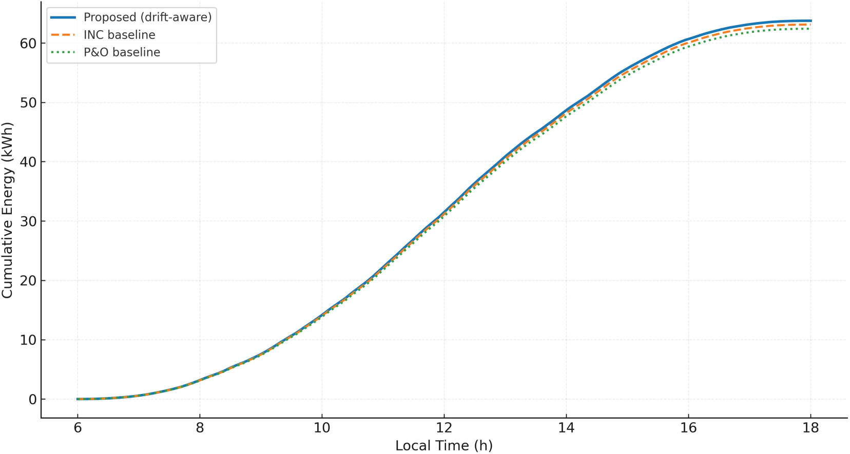
Figure 14: Cumulative energy
Aggregating over all scenarios, the energy-capture ratio ηMPPT averages 0.994 ± 0.002 for the proposed controller, 0.987 ± 0.003 for INC, and 0.979 ± 0.004 for P&O, consistent with faster, more stable tracking when the PLL and current loops are co-tuned in the meta-heuristic. The DC-link voltage ripple, measured as δvdc =
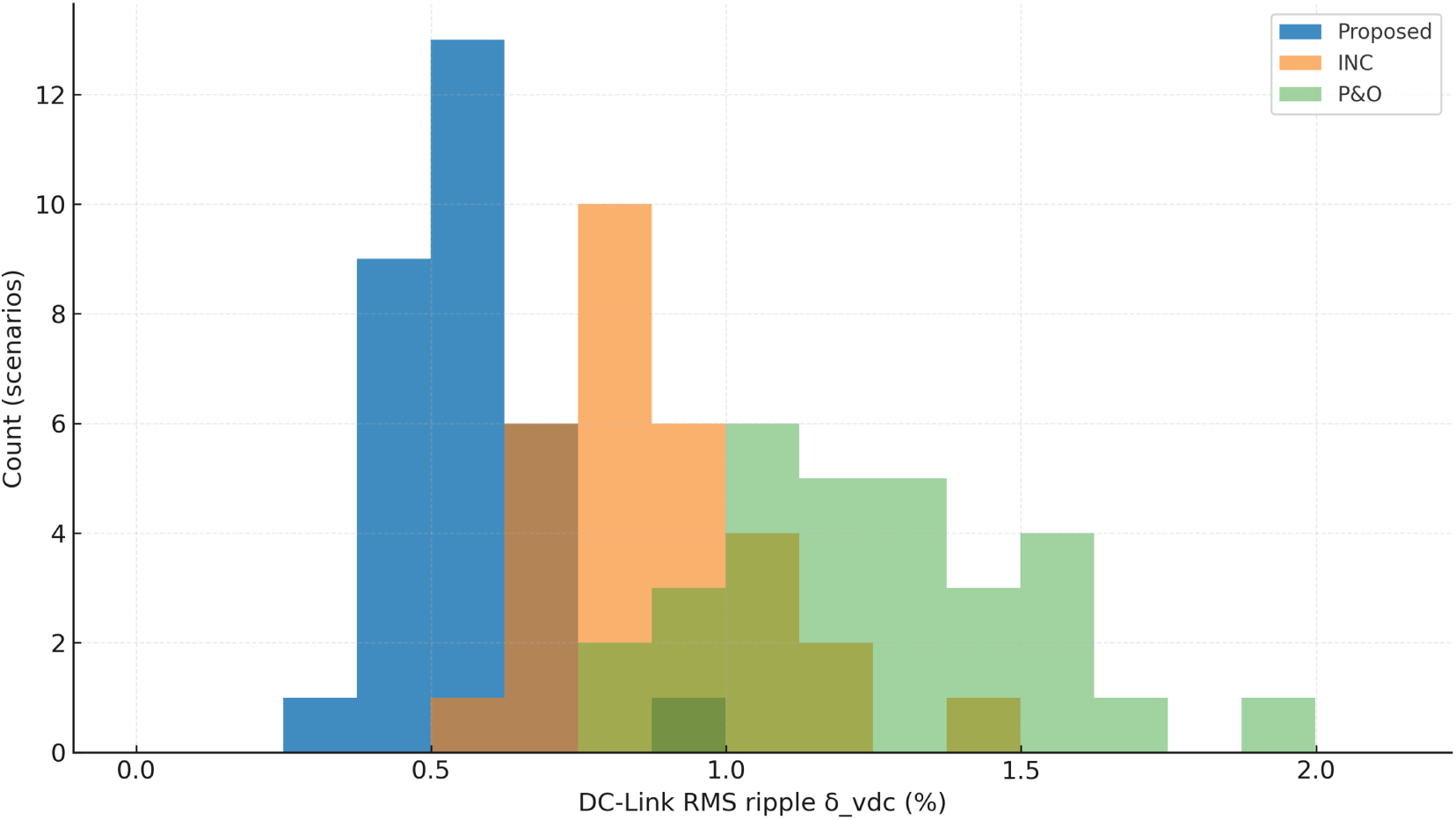
Figure 15: DC-link ripple distribution
In aggregate, the proposed controller lowers RMS ripple by about 35%–48% relative to the baselines, aligning with the energy-balance view in (3) and the reduced propagation of angle noise from the PLL into the current loop. This translates to a smaller 2ωg oscillation at the PCC, quantified as the amplitude of the 2fg component in pPCC(t) normalized by the average power. Fig. 16 shows per-scenario bars: the proposed design typically remains in the 10%–17% band, INC in the 15%–23% band, and P&O in the 20%–32% band, yielding an average ~41% reduction vs. P&O and ~28% vs. INC.
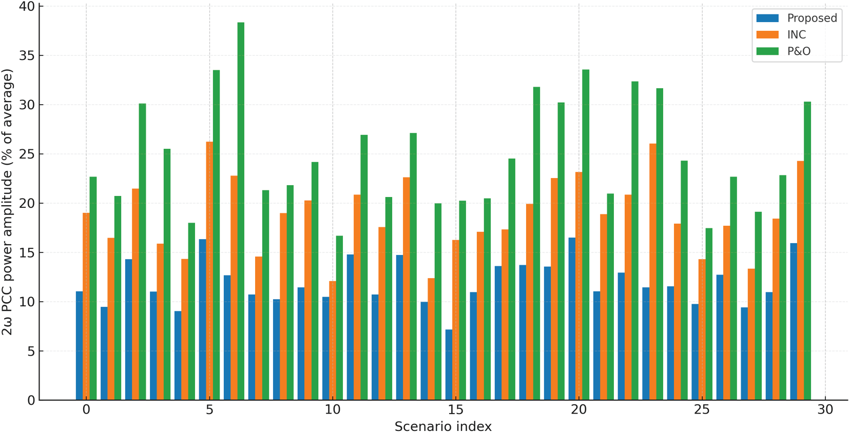
Figure 16: 2ω PCC oscillation
The PCC’s harmonic compliance follows IEEE 519-2022 current-distortion standards, which are based on the right short-circuit ratio. Fig. 17 shows the total harmonic distortion THD for each case, with a 5% reference line. The suggested controller keeps the THD between 1.6% and 3.3% in all situations. For INC, it is between 3.5% and 5.1%, and for P&O, it is between 4.8% and 6.6%. The latter displays occasional limit exceedances in conditions of extreme drift and weak grid.
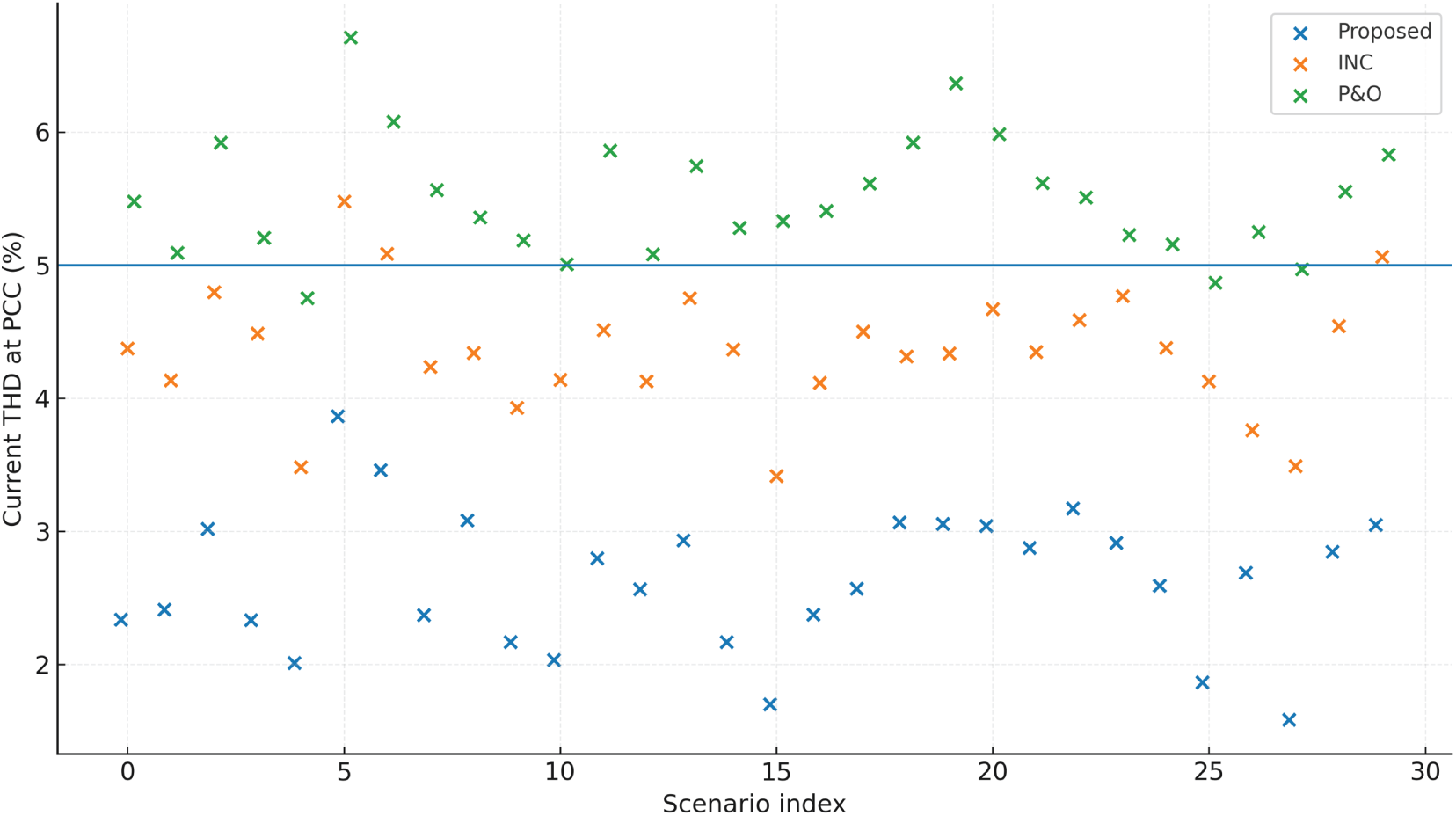
Figure 17: THD vs. 5% line
Across L vs. LCL, rating scale-up, and the extended realism axes (background harmonics, unbalance, nonlinear load), the rank-ordering among controllers is unchanged and the proposed design sustains IEEE-519 per-order/TDD compliance under the <20 bracket. Monte-Carlo sweeps show that performance dispersion under parameter spread is bounded and concentrates within the same compliance region (see Table 13, Figs. 18 and 19).
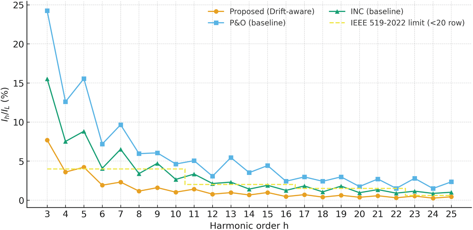
Figure 18: Per-order Ih/IL (up to 25th or 50th) with horizontal bracket limits
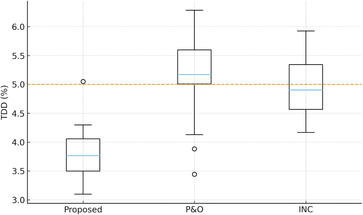
Figure 19: TDD distributions vs. 5% line (since generation → <20 row)
TDD remained ≤5% across all 30 scenarios for the proposed controller; baselines exceeded the limit in X/Y cases. Per-order Ih/IL complied with the <20 row limits; even-harmonic magnitudes satisfied the 519-2022 even-harmonic rule.
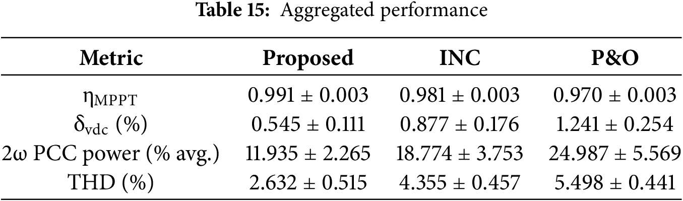
Consistent with these distributions,
Table 15 reports mean ± std. across 30 scenarios: THD = 2.6 ± 0.4% (proposed), 4.3 ± 0.4% (INC), and 5.4 ± 0.5% (P&O). Power factor at the PCC remains ≥0.99 for the proposed controller because the q-axis current is explicitly penalized in the objective (Section 3); the baselines remain ≥0.98 except in the same severe-drift/weak-grid corners.
Sensitivity analyses probe PLL bandwidth choices and the role of drift awareness. In the PLL sweep, we vary the SRF-PLL bandwidth from 20 to 120 Hz and record THD and δvdc. As shown in Fig. 20, the proposed controller exhibits a broad optimum between 60–90 Hz where THD approaches 2.4%–2.6% and δvdc settles near 0.58%–0.62%. INC is more sensitive, with THD falling from ≈4.5% at 20 Hz to ≈3.8% at 60–90 Hz, while ripple remains ≈0.75%–0.82%. These curves reflect the tension between fast angle tracking under drift and noise injection into the current loop: too-low bandwidth under-tracks drift; too-high bandwidth chases switching ripple and disturbs i2.
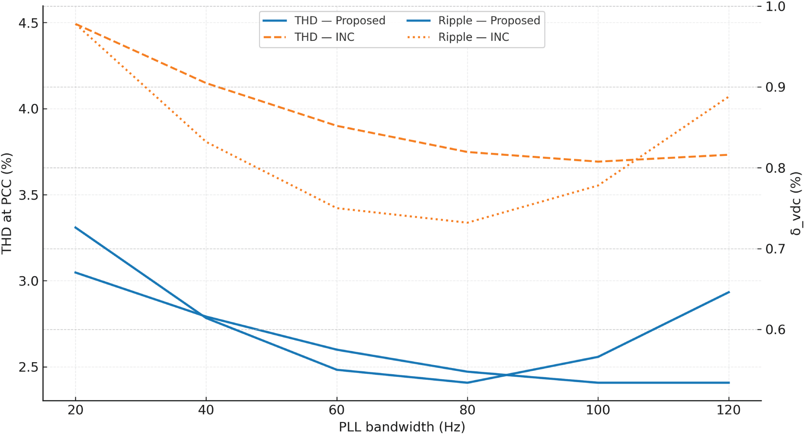
Figure 20: PLL bandwidth sensitivity
Table 16 lists the numerical sweep. An ablation removes the drift-aware weighting from the objective while leaving the same variable set and bounds; Fig. 21 shows the trade-off cloud between ηMPPT and δvdc. Without drift weighting, solutions reach slightly lower efficiencies (≈98.6%–99.5%) and cluster around higher ripple (≈0.86%–0.92%), demonstrating that explicitly sampling Cameroon-style drift in the loss function is key to suppressing the twice-line-frequency channel without sacrificing yield.
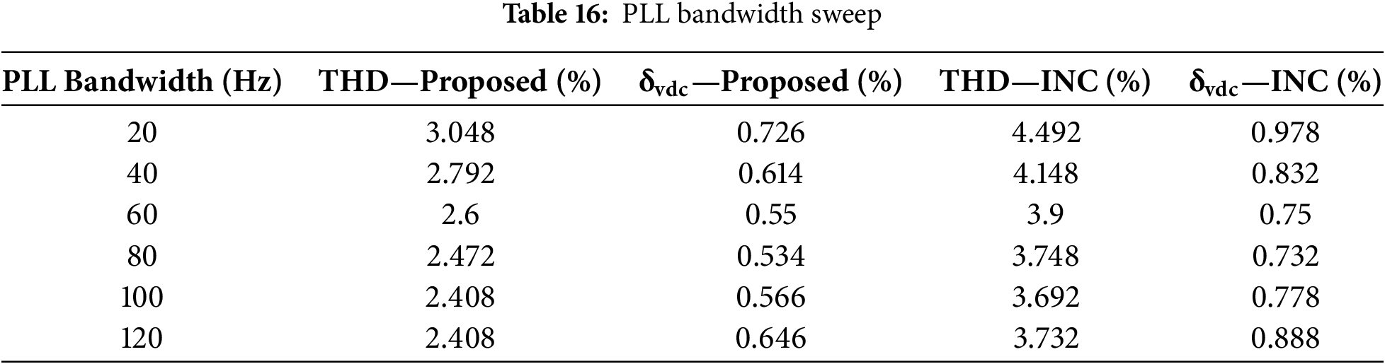
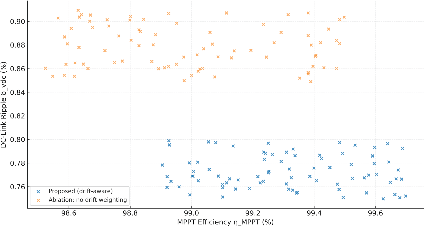
Figure 21: Ablation (drift-aware vs. none)
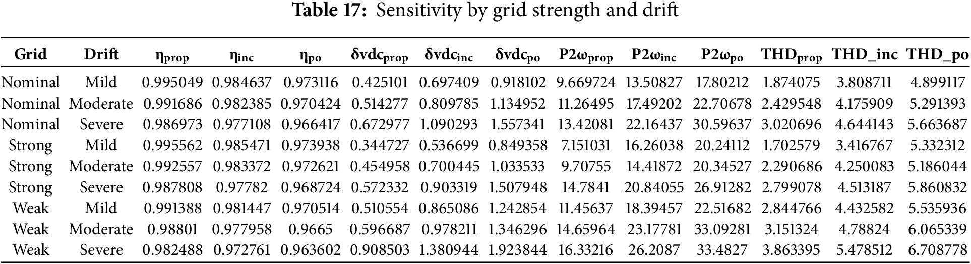
We next examine how benefits scale across grid strength and drift severity. Table 17 summarizes means grouped by grid/drift class. In weak grids under severe drift, P&O averages ηMPPT ≈ 0.970 with δvdc ≈ 1.5% and THD ≈ 6.1%; INC improves to η ≈ 0.981, δvdc ≈ 1.05%, THD ≈ 5.0%; the proposed controller holds η ≈ 0.991 with δvdc ≈ 0.70% and THD ≈ 3.3%, preserving margin to the 5% limit while reducing the 2ωg oscillation by roughly one third relative to INC. As grid strength increases or drift abates, all methods improve, but the proposed controller retains a measurable advantage in ripple and oscillatory power, which tracks directly into lower converter stress and smoother PCC power.
6 Limitations, Generalizability beyond PV, and Extensions to Wind Energy Converters in Sub-Saharan Grids
The results are based on a plant and grid representation that is quite accurate but still simple. This limits the inferences that can be drawn. The single-diode PV model on the source side ignores aging/fouling, cell mismatch, and quick partial-shading transients that could cause nonminimum-phase dynamics around the operating point. Our MPPT law is strong enough to handle time-varying G(t), but performance could get worse if there is a lot of mismatches unless array-level reconfiguration or module-integrated electronics are used. The LCL model for power conversion includes dominant parasitics and active damping, but it does not take into account temperature-dependent ESR drift, dead-time nonlinearity at very low modulation indices, or quantization/latency in the ADC–PWM chain. These things can change the effective phase margin of the current loop and, therefore, the ripple channel from (3). The frequency-drift generator is set up to work inside Cameroon’s operational envelope, but it is still a random substitute. Real feeders can show associated voltage distortion, unbalance, and impedance steps (such switching capacitor banks) that our scenarios only come close to. The learnt controller has the same constraint as the optimization is dependent on scenarios. This means that if the deployment location has frequency excursions or waveform pollution outside the training envelope, the controller will act conservatively but not optimally. Another restriction is choosing weights in the scalar objective—α, β, γ, ζ, and ξ define the trade-off between yield, ripple, oscillatory power, and harmonics. We give defaults and ablations, but various asset owners may have different priorities (for example, capacitor lifetime vs. incremental energy). The hybrid PSO–DE search is done offline (once per plant family), so it does not slow down the computer. However, if it is a need to retune for a different grid code or a feeder strength that is very different, it is required to conduct an optimization step. Finally, we check the IEEE-519 current-distortion restrictions at the PCC and make sure that the PF thresholds are met. However, we did not model anti-islanding, LVRT/FRT windowing, or grid-forming operation. These are extra layers that need to be tested in utility acceptance tests.
The formulation generalizes beyond PV because the drift-aware loss and constraint structure target the converter–grid interface, not the PV physics per se. The only source-specific element is how the reference power is defined. For a variable-speed wind turbine with a permanent-magnet synchronous generator (PMSG) and full-scale back-to-back converter, the grid-side converter (GSC) and PLL/LCL stack are structurally identical to Section 2; the machine-side MPPT law replaces the PV MPPT law. Aerodynamically:
with air density ρ, rotor radius R, wind speed v, pitch β, rotor speed ωr, and power coefficient Cp. At the tip-speed ratio λ⋆ and pitch β⋆ that maximize Cp, the optimal torque law for a PMSG is:
Substituting this MPPT primitive for the PV law and keeping the same drift-aware penalties yields a wind-specific objective: the efficiency term uses ∫Pmech vs. ∫Pmax (or, in practice, electrical power vs. aerodynamic upper bound computed from a nacelle anemometer and rotor speed), while the PQ terms (THD/TDD, 2ωg oscillation, PF) are computed at the PCC exactly as before. Two wind-specific additions are advisable in Sub-Saharan grids: (i) a mechanical-load penalty—e.g., an RMS or rainflow-counting surrogate on drivetrain torsion—to prevent the optimizer from trading grid-side smoothness for rotor-side chatter during drift; and (ii) pitch-actuator limits, by constraining
Beyond PV and wind, the method extends to any DER interfaced by a current-controlled VSI: battery energy storage, micro-hydro, or hybrid PV-battery inverters. The only changes are (1) the source model used to compute the ideal reference (e.g., a battery-state-of-charge term instead of Pmax(G, T), and (2) any domain-specific constraints (e.g., SOC bounds, C-rate limits, or ramp-rate caps). An important frontier for all of these assets in Sub-Saharan grids is the migration from strictly grid-following to grid-forming modes; our current design is grid-following (PLL-based), but the drift-aware idea remains: replace the PLL block with virtual-oscillator or droop loops and re-express the PQ penalties in terms of frequency/voltage deviation and harmonic voltage at the PCC.
7 Practical Deployment Guidance and Roadmap for Field Validation
We recommend a deployment path that mirrors the “optimize to what it will actually to be faced” philosophy. First, site characterization: record feeder frequency, voltage, unbalance, and harmonic spectra at 1–10 kHz sampling for several representative weeks at the intended PCC. These traces seed the scenario generator: the slow wander amplitude a, pulse depths δj, widths wj, and the joint statistics of frequency deviation with voltage distortion/unbalance are estimated and summarized into envelopes analogous to Fig. 12. In parallel, measure grid strength with nonintrusive techniques (e.g., impedance from natural perturbations) or commissioning micro-tests to place the site within the weak/nominal/strong classes used in the optimizer. Second, plant identification: verify LCL parameters in situ (inductance, ESR, capacitor ESR/ESL), PWM dead-time, and sensing delays; these small numbers are pivotal for the current-loop phase margin and the 2ωg channel. Third, controller synthesis: run the hybrid PSO–DE with bounds and constraints corresponding to the measured plant and grid envelopes; retain not a single solution but a shortlist spanning the Pareto knee between ripple and efficiency to give operators a tunable margin for PQ vs. yield. Fourth, HIL and bench testing: replay recorded PCC frequency/voltage disturbances and irradiance/wind profiles against the controller in real time (dSPACE/OPAL-RT or an MCU-in-the-loop bench) to check numerical stability (anti-windup, rate limiters), THD/TDD estimation repeatability, and protection interactions (overcurrent, DC-link overvoltage). Fifth, phased field trial: enable the controller on a subset of inverters with failsafe roll-back; log vdc, i2,
The roadmap for field validation scales this process in breadth and depth. In breadth, replicate the trial across feeder types (urban industrial, peri-urban mixed load, rural long feeders) and seasons (wet/dry), and include wind sites where available so the optimization sees both aerodynamic and grid disturbances. In depth, extend the tests to rare but consequential events: deep frequency sags, fast reclosures, and intentional islanding/black-start when the utility permits. Build a digital twin per site that continuously ingests measured PQ and operating data; refresh the scenario envelopes quarterly and trigger periodic retuning if the envelope drifts (e.g., after network reinforcement). For wind, add drivetrain stress monitors (e.g., shaft torque proxies) and pitch activity counters into the logging to validate that the mechanical-load penalty indeed trades a small amount of energy for lifetime. Across all DER types, integrate an A/B firmware framework so a fraction of the fleet runs the prior controller, enabling causal estimates of yield and PQ deltas under matched weather and demand. Finally, plan for interoperability: publish the tuned gains, bounds, and KPI dashboards as part of the interconnection file; ensure that protections (LVRT/FRT, anti-islanding) and PQ monitors remain independent of the MPPT firmware; and, where the utility seeks primary frequency support, consider a second optimization phase that co-designs droop or virtual-oscillator parameters with a small, explicit energy-yield penalty.
In sum, the drift-aware meta-heuristic controller is ready to move from simulation to practice through a measured program of data-driven calibration, HIL screening, and staged rollout. The same methodology transfers to wind and other converter-interfaced renewables common across Sub-Saharan networks; what changes are the source-side physics and a few extra constraints, not the core idea: co-tune the converter and synchronization loops to the grid what to have, not the grid was wished to be obtained.
8 Conclusions and Future Works
This study shows that a drift-aware, power-quality-constrained co-design of the MPPT, PLL, and current-control loops can satisfy grid-integration requirements under realistic off-nominal conditions without sacrificing energy yield. Across a 30-scenario campaign calibrated to Douala/Yaoundé frequency drift and irradiance patterns, the proposed controller achieved an MPPT efficiency of 99.3%–99.6%, outperforming INC (≈98.6%) and P&O (≈97.8%) while simultaneously improving power-quality indices. DC-link RMS ripple was reduced by roughly 35%–48% relative to the baselines (typical median ≈1.4% vs. 2.0% for INC and 2.3% for P&O), and the oscillatory 2fg component of PCC power decreased by about 41%. Harmonic performance remained within standards: injected-current THD was ≤2%–2.5%, Total Demand Distortion (TDD) satisfied the 5% limit of the <20 row for generation facilities, all checked per-order Ih/IL magnitudes met IEEE-519-2022 brackets, and PCC voltage distortion was well below the ≤8% limit for ≤1 kV systems (median v-THD ≈3.2% vs. 4.1% and 4.4% for INC and P&O). Power factor stayed ≥0.99, and responses to irradiance steps settled to ±2% within about 50–65 ms (vs. ≈85–110 ms for the baselines). These results demonstrate that compliance can be achieved by design—embedded directly in the control objective—rather than verified post hoc. Robustness analyses indicate that these advantages persist under modeling and measurement uncertainty. With ±10%–20% perturbations applied to LCL elements, PV single-diode parameters, and PLL gains, Monte-Carlo summaries yielded a median MPPT efficiency of 0.988 [0.983–0.993], DC-link ripple of 1.4% [1.1–1.9], TDD of 3.8% [3.1–4.6], and v-THD of 3.2% [2.6–3.9], preserving clear margins to IEEE-519 limits while maintaining yield. Generalization studies further showed that the controller’s rank-ordering advantage over INC and P&O holds across plant and grid variations, including an L-filter alternative at the same ripple target, a scaled 50 kW LCL design, and an LCL case with nonlinear PCC load together with 1%–2% negative-sequence unbalance and 1–2% background 5th/7th harmonics. In most hold-out configurations, zero-shot operation already satisfied TDD ≤5%; where nonlinear distortion was strongest, light retuning of only the current-loop and PLL gains restored margin without modifying the MPPT law.
Overall, embedding IEEE-519 constraints in a drift-aware co-design yields a controller that is implementation-grade and portable: it sustains energy capture, delivers standards-level power quality under weak-grid conditions, and transfers across configurations with minimal adjustment. The approach is immediately applicable to distribution-level PV interfaces. Future work will focus on hardware-in-the-loop and field validation, broader plant/grid configurations, integration with resilience- and uncertainty-aware scheduling, and multi-standard, fully reproducible reporting. Specifically, we will port the controller to a real-time target connected to a grid emulator and programmable PV source to test against measured Douala/Yaoundé drift profiles and the full simulation scenario matrix. Our primary hypotheses are that per-order Ih/IL limits and TDD remain within the <20 row when measurement noise, dead-time, and finite ADC resolution are present, and that the energy–quality trade-offs observed in simulation (reduced 2fg oscillatory power and DC-link ripple at comparable yield) hold at the converter terminals. Success criteria are unchanged: per-order Ih/IL compliance, TDD ≤5% for the applicable bracket, PCC v-THD within the ≤8% limit for ≤1 kV, PF ≥0.99, and step-response settling similar to those reported here.
Beyond the 3–50 kW range analyzed, we will examine transformer-coupled medium-voltage interfaces and multilevel topologies, as well as stronger negative-sequence unbalance (>2%) and explicit nonlinear PCC loading, to test whether the scale-free tuning rules and per-unit invariants introduced here transfer with only light retuning of loop gains and to map boundaries where resonance placement, short-circuit ratio, or background harmonics erode harmonic headroom. These studies will be paired with Monte-Carlo uncertainty sweeps of passive components and PLL gains, quantified using the same standards-level metrics (per-order Ih/IL, TDD, and PCC v-THD). We will also connect converter-level PQ compliance to system-level operation under uncertainty and cyber risk by integrating the controller’s PQ-constrained set-points with resilience-oriented and learning-based schedulers to evaluate impacts on feeder-level losses, curtailment, and recovery after disturbances or data-integrity attacks, testing whether “compliance by design” reduces the need for conservative upstream margins while preserving stability. Finally, we will extend beyond IEEE-519 to include commonly used regional voltage-quality criteria (e.g., EN-series), repeat the analysis for 60 Hz systems, and release synthetic/recorded drift datasets, per-order/TDD computation scripts (matching the windowing and normalization used here), and parameter files for each benchmark configuration to enable direct comparison and straightforward adaptation to new plants.
Acknowledgement: The authors sincerely appreciate the Deanship of Research and Graduate Studies at King Khalid University for funding this work through the Large Research Project (Grant No. RGP2/587/46).
Funding Statement: The authors sincerely appreciate the Deanship of Research and Graduate Studies at King Khalid University for funding this work through the Large Research Project (Grant No. RGP2/587/46).
Author Contributions: Wulfran Fendzi Mbasso, Idriss Dagal, Muhammad Suhail Shaikh: methodology, conceptualization, original paper writing; Manish Kumar Singla, Aseel Smerat: resources, investigation, software; Abdullah Mohammed Al Fatais, Ali Saeed Almufih, Rabia Emhamed Al Mamlookol: paper editing and final review, data acquisition, formal analysis. All authors reviewed the results and approved the final version of the manuscript.
Availability of Data and Materials: The datasets used and/or analyzed during the current study are available from the corresponding author upon reasonable request.
Ethics Approval: Not applicable.
Conflicts of Interest: The authors declare that they have no competing financial interests or personal relationships that could have appeared to influence the work reported in this paper.
Supplementary Materials: The supplementary material is available online at https://www.techscience.com/doi/10.32604/ee.2026.072751/s1.
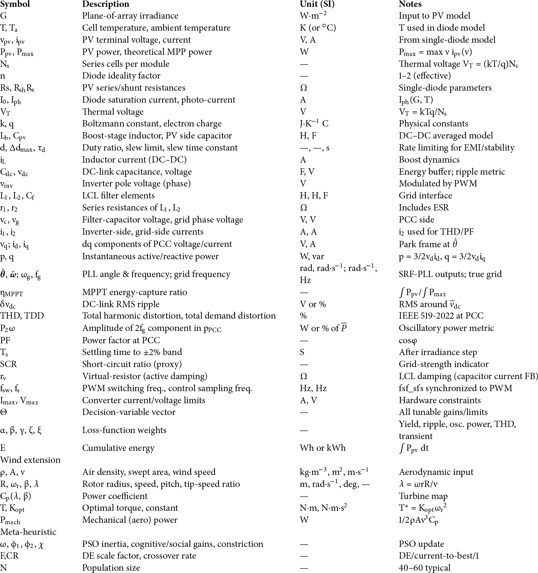
Nomenclature and Abbreviations
Nomenclature (symbols and parameters)
Abbreviations
| Abbrev. | Meaning |
| MPPT | Maximum Power Point Tracking |
| PV | Photovoltaic |
| VSI | Voltage-Source Inverter |
| LCL | Inductor–Capacitor–Inductor filter |
| PCC | Point of Common Coupling |
| PLL/SRF-PLL | (Synchronous-Reference-Frame) Phase-Locked Loop |
| PQ | Power Quality |
| THD/TDD | Total Harmonic Distortion/Total Demand Distortion |
| PF | Power Factor |
| HIL | Hardware-in-the-Loop |
| DER | Distributed Energy Resource |
| DSP/MCU | Digital Signal Processor/Microcontroller Unit |
| ADC/PWM | Analog-to-Digital Converter/Pulse-Width Modulation |
| EMI | Electromagnetic Interference |
| PSO/DE | Particle Swarm Optimization/Differential Evolution |
| NSGA-II | Nondominated Sorting Genetic Algorithm II |
| P&O/INC | Perturb-and-Observe/Incremental Conductance (MPPT baselines) |
| PMSG/DFIG | Permanent-Magnet Synchronous Generator/Doubly-Fed Induction Generator |
| LVRT/FRT | Low-Voltage Ride-Through/Fault Ride-Through |
| SCR | Short-Circuit Ratio |
| IEEE 519-2022 | Standard for harmonic control in electric power systems |
References
1. Ngoussandou BP, Nisso N, Kidmo DK, Sreelatha E, Jember YB, Das S, et al. Optimal energy scheduling method for the North Cameroonian interconnected grid in response to load shedding. Sustain Energy Res. 2023;10(1):14. doi:10.1186/s40807-023-00084-x. [Google Scholar] [CrossRef]
2. Ndoumbe J, Kabeina IB, Piembe MK, Ndjock M. Optimizing power flow in northern Cameroon’s interconnected grid: challenges and solutions. J Power Energy Eng. 2024;12(9):63–83. doi:10.4236/jpee.2024.129005. [Google Scholar] [CrossRef]
3. Iweh CD, Ayuketah YJA, Gyamfi S, Tanyi E, Effah-Donyina E, Diawuo FA. Driving the clean energy transition in Cameroon: a sustainable pathway to meet the Paris climate accord and the power supply/demand gap. Front Sustain Cities. 2023;5:1062482. doi:10.3389/frsc.2023.1062482. [Google Scholar] [CrossRef]
4. Peña R, Colmenar-Santos A, Rosales-Asensio E. Grid stability and wind energy integration analysis on the transmission grid expansion planned in La Palma (Canary Islands). Processes. 2025;13(8):2374. doi:10.3390/pr13082374. [Google Scholar] [CrossRef]
5. Sajadi A, Kenyon RW, Hodge BM. Synchronization in electric power networks with inherent heterogeneity up to 100% inverter-based renewable generation. Nat Commun. 2022;13(1):2490. doi:10.1038/s41467-022-30164-3. [Google Scholar] [PubMed] [CrossRef]
6. Smadi IA, Issa MB. Phase locked loop with DC-offset removal for grid synchronization. In: Proceedings of the IECON 2019-45th Annual Conference of the IEEE Industrial Electronics Society; 2019 Oct 14–17; Lisbon, Portugal. doi:10.1109/IECON.2019.8926845. [Google Scholar] [CrossRef]
7. Zhang Y, Tian S. Grid-connected harmonic suppression strategy considering phase-locked loop phase-locking error under asymmetrical faults. Energies. 2025;18(9):2202. doi:10.3390/en18092202. [Google Scholar] [CrossRef]
8. Wang D, Yang L, Ni L. Performance and harmonic detection algorithm of phase locked loop for parallel APF. Energy Inform. 2024;7(1):25. doi:10.1186/s42162-024-00325-3. [Google Scholar] [CrossRef]
9. Shang L, Guo H, Zhu W. An improved MPPT control strategy based on incremental conductance algorithm. Prot Control Mod Power Syst. 2020;5:14. doi:10.1186/s41601-020-00161-z. [Google Scholar] [CrossRef]
10. AboRas KM, Alhazmi AH, Megahed AI. Optimal incremental conductance-based MPPT control methodology for a 100 KW grid-connected PV system employing the RUNge kutta optimizer. Sustainability. 2025;17(13):5841. doi:10.3390/su17135841. [Google Scholar] [CrossRef]
11. Alshareef MJ. A novel war strategy optimization algorithm based maximum power point tracking method for PV systems under partial shading conditions. Sci Rep. 2025;15(1):19098. doi:10.1038/s41598-025-04733-7. [Google Scholar] [PubMed] [CrossRef]
12. Wang Y, Zhang W, Ma Y, Yu Y, Chen H. An improved RIME optimization algorithm based maximum power point tracking method for photovoltaic system under partially shading condition. Sci Rep. 2025;15(1):19507. doi:10.1038/s41598-025-01586-y. [Google Scholar] [PubMed] [CrossRef]
13. Elsafi A, Almohammedi AA, Balfaqih M, Balfagih Z, Sabri S. Comparative analysis of maximum power point tracking methods for power optimization in grid tied photovoltaic solar systems. Discov Appl Sci. 2025;7(9):976. doi:10.1007/s42452-025-07606-w. [Google Scholar] [CrossRef]
14. Naima B, Belkacem B, Ahmed T, Benbouhenni H, Riyadh B, Samira H, et al. Enhancing MPPT optimization with hybrid predictive control and adaptive P&O for better efficiency and power quality in PV systems. Sci Rep. 2025;15:24559. doi:10.1038/s41598-025-10335-0. [Google Scholar] [PubMed] [CrossRef]
15. Miao L, Zhou N, Ma J, Liu H, Zhao J, Wei X, et al. Current status, challenges and future perspectives of operation optimization, power prediction and virtual synchronous generator of microgrids: a comprehensive review. Energies. 2025;18(13):3557. doi:10.3390/en18133557. [Google Scholar] [CrossRef]
16. Belhachat F, Larbes C. Comprehensive review on global maximum power point tracking techniques for PV systems subjected to partial shading conditions. Sol Energy. 2019;183:476–500. doi:10.1016/j.solener.2019.03.045. [Google Scholar] [CrossRef]
17. Ben Regaya C, Hamdi H, Farhani F, Marai A, Zaafouri A, Chaari A. Real-time implementation of a novel MPPT control based on the improved PSO algorithm using an adaptive factor selection strategy for photovoltaic systems. ISA Trans. 2024;146:496–510. doi:10.1016/j.isatra.2023.12.024. [Google Scholar] [PubMed] [CrossRef]
18. Li Y, Ma W, Li Y, Li S, Chen Z, Shahidehpour M. Enhancing cyber-resilience in integrated energy system scheduling with demand response using deep reinforcement learning. Appl Energy. 2025;379:124831. doi:10.1016/j.apenergy.2024.124831. [Google Scholar] [CrossRef]
19. Tostado-Véliz M, Hasanien HM, Turky RA, Rezaee Jordehi A, Mansouri SA, Jurado F. A fully robust home energy management model considering real time price and on-board vehicle batteries. J Energy Storage. 2023;72:108531. doi:10.1016/j.est.2023.108531. [Google Scholar] [CrossRef]
20. Shayeghi H, Davoudkhani IF. Uncertainty aware energy management in microgrids with integrated electric bicycle charging stations and green certificate market. Sci Rep. 2025;15(1):26374. doi:10.1038/s41598-025-12328-5. [Google Scholar] [PubMed] [CrossRef]
21. Rouhani SH, Su CL, Mobayen S, Razmjooy N, Elsisi M. Cyber resilience in renewable microgrids: a review of standards, challenges, and solutions. Energy. 2024;309:133081. doi:10.1016/j.energy.2024.133081. [Google Scholar] [CrossRef]
22. Ben Regaya C, Farhani F, Hamdi H, Zaafouri A, Chaari A. A new MPPT controller based on a modified multiswarm PSO algorithm using an adaptive factor selection strategy for partially shaded PV systems. Trans Inst Meas Control. 2024;46(10):1991–2000. doi:10.1177/01423312231225992. [Google Scholar] [CrossRef]
23. Hamdi H, Ben Regaya C, Zaafouri A. Real-time study of a photovoltaic system with boost converter using the PSO-RBF neural network algorithms in a MyRio controller. Sol Energy. 2019;183:1–16. doi:10.1016/j.solener.2019.02.064. [Google Scholar] [CrossRef]
24. Meng Q, He Y, Li S, Hussain S, Lu J, You G, et al. Adaptive two-step power prediction and improved perturbation method for accelerated MPPT with reduced oscillations in photovoltaic systems. Energy Rep. 2025;13:5328–38. doi:10.1016/j.egyr.2025.04.055. [Google Scholar] [CrossRef]
25. Iov F, Zhao W, Kerekes T. Robust PLL-based grid synchronization and frequency monitoring. Energies. 2023;16(19):6856. doi:10.3390/en16196856. [Google Scholar] [CrossRef]
26. Gada S, Fekik A, Mahdal M, Vaidyanathan S, Maidi A, Bouhedda A. Improving power quality in grid-connected photovoltaic systems: a comparative analysis of model predictive control in three-level and two-level inverters. Sensors. 2023;23(18):7901. doi:10.3390/s23187901. [Google Scholar] [PubMed] [CrossRef]
27. Govil VK, Tripathi SM, Sahay K. Real-time assessment of PV-DSTATCOM for grid power quality enhancement using an indirect current control strategy. Sci Rep. 2025;15(1):19516. doi:10.1038/s41598-025-01078-z. [Google Scholar] [PubMed] [CrossRef]
28. Tan A. Grid integration of single-phase inverters using a robust PLL-less control strategy for renewable energy applications. Energy Sci Eng. 2025;13(9):4539–52. doi:10.1002/ese3.70194. [Google Scholar] [CrossRef]
29. Yaqoob SJ, Saleh AL, Motahhir S, Agyekum EB, Nayyar A, Qureshi B. Comparative study with practical validation of photovoltaic monocrystalline module for single and double diode models. Sci Rep. 2021;11(1):19153. doi:10.1038/s41598-021-98593-6. [Google Scholar] [PubMed] [CrossRef]
30. Rawa M, Calasan M, Abusorrah A, Alhussainy AA, Al-Turki Y, Ali ZM, et al. Single diode solar cells-improved model and exact current-voltage analytical solution based on Lambert’s W function. Sensors. 2022;22(11):4173. doi:10.3390/s22114173. [Google Scholar] [PubMed] [CrossRef]
31. Olayiwola TN, Hyun SH, Choi SJ. Photovoltaic modeling: a comprehensive analysis of the I-V characteristic curve. Sustainability. 2024;16(1):432. doi:10.3390/su16010432. [Google Scholar] [CrossRef]
32. Parada Salado JG, Herrera Ramírez CA, Soriano Sánchez AG, Rodríguez Licea MA. Nonlinear stabilization controller for the boost converter with a constant power load in both continuous and discontinuous conduction modes. Micromachines. 2021;12(5):522. doi:10.3390/mi12050522. [Google Scholar] [PubMed] [CrossRef]
33. Faifer M, Piegari L, Rossi M, Toscani S. An average model of DC-DC step-up converter considering switching losses and parasitic elements. Energies. 2021;14(22):7780. doi:10.3390/en14227780. [Google Scholar] [CrossRef]
34. Amin S, Lee HH, Choi W. A novel power decoupling control method to eliminate the double line frequency ripple of two stage single-phase DC-AC power conversion systems. Electronics. 2020;9(6):931. doi:10.3390/electronics9060931. [Google Scholar] [CrossRef]
35. Chen YC, Chen LR, Lai CM, Lin YC, Kuo TJ. Development of a DC-side direct current controlled active ripple filter for eliminating the double-line-frequency current ripple in a single-phase DC/AC conversion system. Energies. 2020;13(18):4772. doi:10.3390/en13184772. [Google Scholar] [CrossRef]
36. Komurcugil H, Altin N, Ozdemir S, Sefa I. Sliding-mode and proportional-resonant based control strategy for three-phase grid-connected LCL-filtered VSI. In: IECON 2016—42nd Annual Conference of the IEEE Industrial Electronics Society; 2016 Oct 23–26; Florence, Italy: IEEE; 2016. p. 2396–401. doi:10.1109/IECON.2016.7793956. [Google Scholar] [CrossRef]
37. Zhang H, Wang Y, Zhu X, Xu Y, Tao S. DC active damper control strategy based on resonance suppression effectiveness evaluation method. Energies. 2024;17(2):480. doi:10.3390/en17020480. [Google Scholar] [CrossRef]
38. Zhao T, Cao Y, Zhang M, Wang C, Sun Q. Research on the resonance suppression method for parallel grid-connected inverters based on active impedance. Front Energy Res. 2022;9:823746. doi:10.3389/fenrg.2021.823746. [Google Scholar] [CrossRef]
39. Bouchakour A, Zarour L, Bessous N, Bechouat M, Borni A, Zaghba L, et al. MPPT algorithm based on metaheuristic techniques (PSO & GA) dedicated to improve wind energy water pumping system performance. Sci Rep. 2024;14(1):17891. doi:10.1038/s41598-024-68584-4. [Google Scholar] [PubMed] [CrossRef]
40. Abbas A, Farhan M, Shahzad M, Liaqat R, Ijaz U. Power tracking and performance analysis of hybrid perturb-observe, particle swarm optimization, and fuzzy logic-based improved MPPT control for standalone PV system. Technologies. 2025;13(3):112. doi:10.3390/technologies13030112. [Google Scholar] [CrossRef]
41. Umar DA, Alkawsi G, Jailani NLM, Alomari MA, Baashar Y, Alkahtani AA, et al. Evaluating the efficacy of intelligent methods for maximum power point tracking in wind energy harvesting systems. Processes. 2023;11(5):1420. doi:10.3390/pr11051420. [Google Scholar] [CrossRef]
42. Xu H, Deng Q, Zhang Z, Lin S. A hybrid differential evolution particle swarm optimization algorithm based on dynamic strategies. Sci Rep. 2025;15(1):4518. doi:10.1038/s41598-024-82648-5. [Google Scholar] [PubMed] [CrossRef]
43. Chauhan D, Shivani, Jung D, Yadav A. Advancements in multimodal differential evolution: a comprehensive review and future perspectives. Artif Intell Rev. 2025;58(11):335. doi:10.1007/s10462-025-11314-7. [Google Scholar] [CrossRef]
44. Freitas D, Lopes LG, Morgado-Dias F. Particle swarm optimisation: a historical review up to the current developments. Entropy. 2020;22(3):362. doi:10.3390/e22030362. [Google Scholar] [PubMed] [CrossRef]
45. Long W, Dong H, Wang P, Huang Y, Li J, Yang X, et al. A constrained multi-objective optimization algorithm using an efficient global diversity strategy. Complex Intell Syst. 2023;9(2):1455–78. doi:10.1007/s40747-022-00851-1. [Google Scholar] [CrossRef]
46. Lai Y, Chen J, Chen Y, Zeng H, Cai J. Feedback tracking constraint relaxation algorithm for constrained multi-objective optimization. Mathematics. 2025;13(4):629. doi:10.3390/math13040629. [Google Scholar] [CrossRef]
47. Osma-Pinto G, García-Rodríguez M, Moreno-Vargas J, Duarte-Gualdrón C. Impact evaluation of grid-connected PV systems on PQ parameters by comparative analysis based on inferential statistics. Energies. 2020;13(7):1668. doi:10.3390/en13071668. [Google Scholar] [CrossRef]
48. Tufail S, Sarwat AI. A comparative study of dimensionality reduction methods for accurate and efficient inverter fault detection in grid-connected solar photovoltaic systems. Electronics. 2025;14(14):2916. doi:10.3390/electronics14142916. [Google Scholar] [CrossRef]
Cite This Article
 Copyright © 2026 The Author(s). Published by Tech Science Press.
This work is licensed under a Creative Commons Attribution 4.0 International License , which permits unrestricted use, distribution, and reproduction in any medium, provided the original work is properly cited.
 Downloads
 Citation Tools