
 Submit a Paper
 Propose a Special lssue
 Open Access
ARTICLE

Koopman-WNN Based MPC for Hierarchical Optimal Voltage and Network Power Loss Control in ADNs
1 Electric Power Research Institute, State Grid Jiangsu Electric Power Company, Nanjing, 211103, China
2 Key Laboratory of Modern Power System Simulation and Control & Renewable Energy Technology, Ministry of Education, Northeast Electric Power University, Jilin, 132012, China
* Corresponding Author: Hao Yang. Email:
Energy Engineering 2026, 123(4), 4 https://doi.org/10.32604/ee.2025.072770
Received 03 September 2025; Accepted 03 November 2025; Issue published 27 March 2026
 View Full Text
 Download PDF
Abstract
With the growing integration of renewable energy sources (RESs) and smart interconnected devices, conventional distribution networks have turned to active distribution networks (ADNs) with complex system model and power flow dynamics. The rapid fluctuation of RES power may easily result in frequent voltage violation issues. Taking the flexible RES reactive power as control variables, this paper proposes a two-layer control scheme with Koopman wide neural network (WNN) based model predictive control (MPC) method for optimal voltage regulation and network loss reduction. Based on Koopman operator theory, a data-driven WNN method is presented to fit a high-dimensional linear model of power flow. With the model, voltage and network loss sensitivities are computed analytically, and utilized for ADN partition and control model formulation. In the lower level, a dual-mode adaptive switching MPC strategy is put forward for optimal voltage control and network loss optimization in each individual partition to decide the RES reactive power. The upper level is to calculate the adjustment coefficients of the RES reactive power given in the low level by taking the coupling effects of different partitions into account, and then the final reactive power dispatches of RESs are obtained to realize optimal control of voltage and network loss. Simulation results on two ADNs demonstrate that the proposed strategy can reliably maintain the voltage at each node within the secure range, reduce network power losses, and enhance the overall system security and economic efficiency.Keywords
In recent years, active distribution networks (ADNs) incorporating high penetration of distributed renewable energy sources (RESs) such as photovoltaic (PV) and wind generators consume more green energy and reduce carbon emissions [1,2]. Moreover, the integration of RESs improves power supply reliability through network reconfiguration capabilities [3]. However, the rapid fluctuation and uncertainty of RESs may easily cause voltage violation issues with over-voltage and under-voltage phenomenon. The increasing integration of distributed resources further transforms distribution networks into non-radial complex structures, which exacerbates the challenges of voltage regulation [4].
Conventional voltage/Var control (VVC) primarily utilizes capacitor banks (CBs) and on-load tap changers (OLTCs) for voltage regulation and power loss mitigation in distribution networks [5]. However, due to the slow speed and discrete property of these devices, they cannot be used to effectively mitigate frequent voltage violations induced by rapid RES fluctuations. To respond to the problems, inverter-based RESs as flexible and fast reactive power support devices have become a promising reactive power resource for VVC. The IEEE 1547.8 standard and a report from the National Renewable Energy Laboratory (NREL) indicate that inverter-based RESs can effectively participate in VVC to improve power quality and save energy [6,7]. In this paper, we focus on RESs’ reactive power regulation for optimal voltage violation regulation and network loss reduction.
Currently, VVC is commonly implemented using centralized, decentralized, and distributed control structures. Centralized control usually utilizes optimal power flow (OPF) as the model fundamental to achieve a globally optimal control effect by coordinating reactive power devices [8]. Ref. [9] proposes a centralized, continuous-time dynamic optimization model based on sensitivity theory to regulate distribution network voltages through PV-inverter reactive power control, where its objective is to minimize the voltage deviation from a reference value. In [10], a robust constrained MPC centralized model is constructed to decide the reference reactive power for each Q(V) controller for online voltage control in ADN. Ref. [11] proposes a time decomposition-based dual-stage model predictive control (MPC) with a reduced model for voltage control and energy loss minimization in ADN. However, centralized control is associated with complex global models and requires massive communication links, which is less effective in online voltage control. In decentralized control, each voltage regulation device makes decisions only based on local measurements, exhibiting characteristics of rapid response and low communication cost. Ref. [12] proposes a reinforcement learning-based decentralized voltage control method that enables cooperative reactive power control among PV inverters without requiring communication between them. Ref. [13] proposes a two-stage local voltage regulation strategy for each region under the partitioning of ADNs. However, decentralized control is easily leading to poor voltage control effectiveness due to a lack of coordination. Distributed control typically adopts a control framework of “grid partitioning and interval communication”, enabling interval-coordinated distributed control based on distributed algorithms. Refs. [14,15] employ an alternating direction method of multipliers (ADMM) to solve the control model within each partition iteratively, achieving distributed voltage control. Ref. [16] proposes a distributed voltage control model, integrating MPC for intra-zone regulation and ADMM for inter-zone coordination. Ref. [17] employs a modified multi-layered recursive least squares technique to partition the network into locally identified regions and realizes the control via a consensus-based fast alternating direction method of multipliers (FADMM). However, distributed control implemented through iterative methods face challenges in large-scale multi-regional power systems. The complexity of interval iteration relationships, the difficulty in accurately constructing the iteration model, and the poor convergence hamper its applicability.
To leverage the complementary attributes of centralized computing (high accuracy, slow response) and decentralized computing (fast response, reduced effectiveness), hybrid control frameworks integrating both paradigms have gained traction. Ref. [18] constructs a two-stage hybrid VVC structure for day-ahead centralized OPF optimization and intraday decentralized fast voltage control. Ref. [19] proposes a hybrid central-local control strategy that uses a centrally computed global strategy to set local DG control curves and further tunes their parameters via distributionally robust optimization (DRO) for enhanced robustness. In [20], inverters are used as control resources to establish a hybrid control model for centralized network loss optimization and local voltage control. Ref. [21] develops a two-layer voltage control scheme considering battery degradation, where a central controller implements multi-stage distributionally robust optimization while local PV inverters regulate reactive power to mitigate fluctuations. The strategic integration of traditional control structures into hybrid frameworks demonstrates adaptability to operating conditions, leveraging their combined advantages and showing significant development potential.
In the above-mentioned literature, voltage control methods driven by power system models typically require to consider power flow constraints. The nonlinearity of power flow poses significant difficulties in solving the control models. To address this issue, Ref. [22] employs intelligent iterative algorithms to solve the nonlinear models. In [23], a new π-type network simplification method is proposed. Then the local rolling optimization model for energy storage system is established based on simplified network. Ref. [24] proposes a control approach leveraging system sensitivity information to construct linearized models, offering high accuracy, ease of solution, and strong applicability. However, traditional sensitivity methods, consisting of Jacobian inversion and perturbation techniques, require precise ADN parameters, limiting practical applicability.
In recent years, data-driven control strategies that do not rely on physical system model and model parameters, deriving control laws from data, exhibit advantages such as adaptability and feasibility. Ref. [25] leverages data to derive an estimation of a sensitivity matrix which is integrated into the transmission network voltage control scheme optimizing the reactive power exchange with ADNs. Refs. [26,27] employ reinforcement learning (RL) approach to obtain the optimal VVC policy. Ref. [28] integrates power grid physics into multi-agent deep reinforcement learning for voltage control, utilizing graph neural networks and transformers to achieve topology-aware coordinated control while enhancing training stability. However, these control models face challenges during the training process due to difficulties in reward setting, long training times, and poor convergence, leading to poor performance in applications.
Notably, recent control models based on data-driven Koopman operator theory [29], as a novel control approach, have found relevant applications in the power system due to the advantages of Koopman method in addressing nonlinear high-dimensional problems. The applications of Koopman method in power systems include scalable transient stability assessment [30], load frequency control [31], and power flow regression [32]. Nevertheless, no existing studies have applied Koopman-based methods to voltage optimization control of ADNs.
In summary, this paper focuses on optimal voltage control in ADNs with a non-radial topology. Driven by heightened operational reliability requirements, non-radial distribution networks are witnessing growing adoption. This paper proposes a two-layer control scheme with Koopman wide neural network (WNN) based MPC method. A system sensitivity model is constructed by integrating Koopman operator theory and WNN. By utilizing the sensitivity, a linear-constrained MPC based voltage control model is proposed for optimal voltage regulation and network loss optimization. The innovations in this paper primarily manifest as follows:
(1) Construct a lower-level and upper-level framework for non-radial ADN control by using Koopman based MPC method. The lower-level control aims to implement MPC for regional subnetworks following online distribution network partitioning, and the upper-level control achieves efficient coordination among partitioned subnetworks.
(2) Propose an adaptive switching control strategy for optimal voltage regulation and power loss optimization. Each regional control system dynamically switches control models based on local voltage operating state, achieving a balance between voltage security and economic operational requirements while avoiding the complexity of multi-objective optimization.
(3) Introduce a Koopman-WNN system sensitivity analysis model that integrates the linearization capability of Koopman operator theory with the high-dimensional mapping of WNN. This model enables data-driven linear regression and sensitivity analysis for power flow and network loss equations, while addressing issues such as empirical lifting function selection in Koopman operators and limited interpretability in WNN.
The remainder of this paper is organized as follows. Section 2 briefly describes the voltage control framework. Section 3 introduces the sensitivity analysis method by Koopman-WNN. Section 4 introduces a two-tier MPC voltage control model with adaptive mode switching under network partitioning. Section 5 presents the control performance by simulations on the modified IEEE 33-bus system and the Caracas ADN test system. Finally, Section 6 draws the conclusions.
This paper proposes a two-layer control framework with Koopman-WNN based MPC method. A data-driven Koopman-WNN method is presented to construct a sensitivity analysis model, providing support for building a voltage control model for ADN with non-radiative topology. And through a hierarchical control algorithm, it achieves a strongly coupled system partitioned coordination control with online partitioning and dual-mode MPC autonomy at the lower level, while the upper-level system coordinates each zone. The structure of the proposed control framework is shown in Fig. 1.
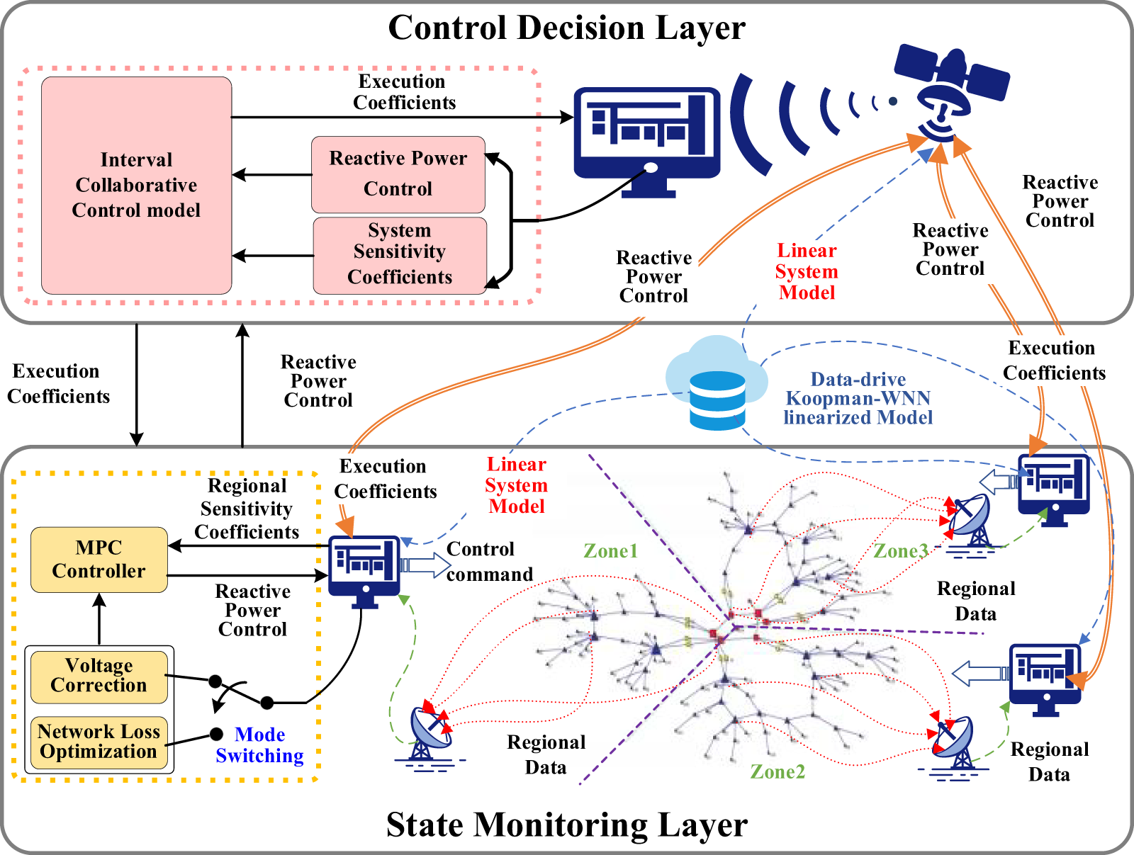
Figure 1: Proposed hierarchical optimization control framework
In Fig. 1, the voltage control system is divided into the state monitoring layer (the lower level) and the control decision layer (the upper level). The state monitoring layer uses the Koopman-WNN linearized model and the current system state for online voltage sensitivity analysis, dynamically partitioning the ADN based on the sensitivity. Within each partitioned region, the MPC-based control objective is adaptively switched between voltage correction mode and network loss optimization mode according to voltage state. By online solving the MPC control model supported by the regional sensitivity coefficients, reactive power control quantities for each region are obtained and uploaded to the control decision layer. The control decision layer utilizes the Koopman-WNN linearized model-supported system sensitivity coefficients to construct a coordination control model accounting for interval coupling effects. By solving this model, coefficients are assigned to the reactive power control quantities uploaded from each region and dispatched to the state monitoring layer. Finally, the control systems in each region at this layer use the assigned coefficients and reactive power control quantities for control, achieving the stable operation of ADN voltages.
3 Koopman-Based Sensitivity Calculation
With the integration of distributed generation (DG), the distribution network has evolved from its original single-source radial structure into a multi-source interconnected non-radial network through the deployment of tie-switches. The power flow has shifted from unidirectional to bidirectional, rendering the current voltage sensitivity analysis method based on the Distflow model no longer applicable. In this section, a data-driven Koopman-WNN linearized model is constructed through an analysis of the linearization mechanism of the power flow equations. Subsequently, this model is utilized to analyze the system’s sensitivity, providing a foundational basis for subsequent power grid optimization and control.
3.1 Data-Drive Koopman-WNN Linear Power Flow Model
The power flow model is formulated based on Kirchhoff’s law as nodal power equations, which expresses the relationship between nodal power and voltages, as shown in Eq. (1).
where Pi and Qi are the active and reactive power injections at node i, respectively; Gik and Bik are respectively the real and imaginary parts at the (i, k) position of the admittance matrix; Ui and Uk are the voltages at nodes i and k; θik is the phase angle difference between nodes i and k; N is the number of nodes in the network. The nonlinearity of this equation makes it challenging to solve voltage optimization control models that consider flow constraints. To address this issue, this paper proposes a high-dimensional linearized power flow equation based on the classical Koopman operator theory, as shown in Eq. (2).
where κPi and κQi denote the high-dimensional Koopman linear operators of the active and reactive power equations; ψPi and ψQi represent the lifting functions for the active and reactive power state variables.
Subsequently, considering the high dimensionality of a single hidden layer in a WNN and its linear relationship with the output layer can effective response to Koopman theory, an interpretable WNN incorporating Koopman mechanism was constructed, as shown in Fig. 2.
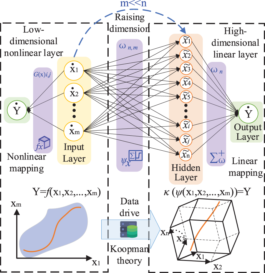
Figure 2: Koopman-WNN framework
In this WNN, the Koopman linearized power flow equations are illustrated as Eqs. (3)–(5):
where κ is the Koopman operators of the equation. Y = (P, Q) is the power matrix of the system;
In Fig. 2, the input layer of the WNN is the low-dimensional state space of Koopman. The hidden layer is the high-dimensional state space of Koopman. The output layer is the linear output space of Koopman. The weighted activation function between the input layer and the hidden layer is the Koopman lifting function, as illustrated in Eq. (6).
where
where ωoutput is the weight matrix. Finally, based on the system-normalized historical power flow data, we construct the Koopman-WNN training dataset. Then we utilize gradient descent to update the network parameters and iteratively train to obtain the lifting function and Koopman linear operator.
In the previous section, leveraging the high-order Taylor expansion linearization of power flow equations as the theoretical foundation, a data-driven Koopman-WNN nonlinear equation linearization model was constructed. In this section, we construct a sensitivity analysis model for the system based on the linearization model.
3.2.1 Voltage Sensitivity Analysis
For voltage sensitivity analysis, the conventional approach involves inversing the Jacobian matrix of the power flow equation. Essentially, the inverse matrix represents the first-order partial derivative matrix of the nonlinear equation U(P, Q), as illustrated in Eqs. (8) and (9):
where U denotes the voltage matrix; P and Q represent the active and reactive power matrices; SU-P and SU-Q are the voltage sensitivity matrices of active and reactive power.
In this study, the Koopman-WNN model is employed to linearize the nonlinear equations U(P, Q). Subsequently, we perform a first-order partial derivative analysis to derive the voltage sensitivity, as illustrated below:
where
where m is the number of the sate variables in the linear equations; i ∈ [1, m/2] and j ∈ [1, m] are the index number of the voltage sensitivity matrix; apq.j is the ith value of vector apq; avθ.j+m/2 is the (i + m/2)th value of vector avθ; ωu.j is the diagonal matrix composed of the j-th column vector of the weight coefficient matrix ωu in the voltage linear equation lifting function Ψu, as shown below:
κu.i+m/2 is the (i + m/2)-th row vector of the Koopman operator κu in the voltage linear equation, as shown below:
where ωu-output.i+m/2,n, is the nth element of the (i + m/2)-th row in the output layer weight coefficient matrix of the voltage equation linearized Koopman-WNN model. Define Ψu⊙ΨuT as the element-wise product of vector Ψu, as shown below:
Through data-driven offline training of the model parameters, real-time analysis of the system’s voltage sensitivity can be achieved with online input of state variables.
3.2.2 Network Loss Sensitivity Analysis
To address network loss sensitivity analysis, the data-driven Koopman-WNN model is utilized to derive the linear expression of the Ploss(P, Q) equation. The first-order partial derivatives are computed to obtain the sensitivity coefficients, as illustrated in the following equation:
where
where κLoss.j is the jth value of the Koopman operator κLoss; ωLoss.j is the diagonal matrix composed of the j-th column vector of the weight coefficient matrix ωLoss.j in the network loss linear equation lifting function ΨLoss, as shown below:
Through data-driven offline training of the model parameters, real-time analysis of the network loss sensitivity can be achieved with online input of state variables.
3.2.3 Dynamic Partitioning Based on Voltage Sensitivity
This section introduces a dynamic reactive power partitioning method for ADN, which adapts the partitioning configuration in real-time according to the dynamic changes in power flow state. The renewable energy inverters serve as the primary reactive power control resources due to their fast reactive power response capability, so they are selected as the leading nodes for partitioning. Non-leading nodes in the grid are clustered based on real-time reactive voltage sensitivity to each leading node, as expressed in Eq. (20).
where PARTi denotes the partition number of node i; Define function Γ[a, A] as retrieving the position index of element ‘a’ within vector A; α represents the number of partitions in the network and is also the leading node identifier; |∂Ui/∂Qα| is the absolute value of the sensitivity coefficient between node i voltage and the leading node α reactive power. |∂Ui/∂Q| is the vector of absolute sensitivity coefficients between node i voltage and the various leading nodes reactive powers.
4 Voltage Hierarchical Control Model
In the context of distributed renewable energy integration, the voltage at each node in the distribution system exhibits pronounced fluctuations corresponding to the variability in renewable energy output, resulting in frequent bidirectional voltage violations. Time-domain MPC algorithms, which consider the future operational states of the system and incorporate rolling-domain feedback corrections, are capable of effectively addressing the uncertainties in system operation, offering enhanced control robustness and reliability. In this section, with a focus on the hierarchical structure of active distribution control systems, we leverage the data-driven Koopman-WNN sensitivity analysis model to construct a partitioned MPC autonomous control model for the state monitoring layer and an interval cooperative control model for the control decision layer.
4.1 The MPC Control Model at the State Monitoring Layer
4.1.1 Adaptive Switching of Regional Control Objectives
The regional control mode autonomously switches between voltage correction and network loss optimization based on local voltage monitoring information. When monitored bus voltages all remain within the secure operating range, network loss optimization control is performed. Otherwise, voltage correction control is executed. The switching mode is as follows:
where
4.1.2 Regional Voltage Correction Control Function
When performing voltage correction control, a time-oriented control objective is established, which combines voltage deviations and control costs as expressed in Eqs. (22) and (23).
where Cv1 > 0, Cv2 > 0 are the weighting coefficients for voltage deviation and control cost; k = 1, …, Nc is the predictive control time domain; Ur(k) is the vector of regional voltage value at time step k; Uref is the reference (desired) value; ΔQr(k) is the reactive power control quantity of new energy inverters within the region; ΔPr(k) is the predicted fluctuation in active power output of new energy at time step k; ∂Ur/∂Qr and ∂Ur/∂Pr are sensitivity vectors between voltage values at various nodes within region and reactive and reactive power from new energy.
4.1.3 Regional Network Loss Optimization Control Function
When performing network loss optimization control, a time-oriented control objective is established, which combines network loss and control costs, as shown in Eqs. (24) and (25).
where CL1 > 0, CL2 > 0 are the weighting coefficients for network loss and control cost; PLoss(k) represents the network loss at time step k; ∂PLoss/∂Qr and ∂PLoss/∂Pr denote the PLoss-Qr sensitivity coefficients and the PLoss-Pr sensitivity coefficients, respectively.
Solving the above objective functions requires satisfying the operational constraints of the new energy sources and voltage safety constraints, as shown in Eq. (26).
where Qr(k) is the reactive power of new energy unit at time step k;
where Pr(k) is the active power of the new energy source at time step k; Sr is the rate capacity of the new energy source.
4.2 Interval Collaborative Control Model at the Control Decision Layer
Due to the regional control system of the state monitoring layer relying solely on local information for decision-making and control, without considering inter-zone coupling effects, the overall coordination performance is insufficient, posing challenges to ensuring effective control. Therefore, this section presents a control decision model designed to minimize both network loss and control performance deviation.
4.2.1 The Coordinated Economic Control Objective Function
In each region, the leading nodes serve as reactive support nodes and nodes implementing coupling effects within the region. Considering the coupling effects between regions, the voltage operational state reflects the overall voltage operation level of the dominated region. Therefore, the objective function of the control model at this layer consists of two parts: system power loss and the deviation in the control effect of dominant node voltage, as illustrated in Eqs. (28) and (29).
where
where ∂ULN.α/∂Qα represents the sensitivity coefficient between the voltage of the α leading node and the reactive power control quantity of the α leading node. ζ is a diagonal matrix composed of the execution coefficients for reactive power in various regions as shown in Eq. (31).
The model solution must satisfy the following constraints:
where U is the voltages in the system after the control devices execute reactive power control based on execution coefficients; Q is the reactive power of control devices; Qnow is the reactive power of control devices at the current time.
By solving this model and assigning execution coefficients to reactive power control quantities uploaded from each region, the interaction among dominant nodes in different regions is balanced, achieving the minimum final control effect deviation and optimal system power loss.
In this study, we validate the applicability of the proposed data-driven Koopman-WNN sensitivity analysis model and the effectiveness of the “physical partitioning and algorithmic hierarchy” dual-mode MPC collaborative optimization control strategy supported by system sensitivity through simulations on the modified IEEE 33-bus system and the modified ADN in the Caracas Metropolitan Area [33]. The simulations were conducted on MATLAB R2022a platform, employing the toolbox YALMIP R2020 for modeling, and utilizing the commercial solver Cplex 12.10.0 for solving.
5.1.1 Construction of the System and Operating Scenarios
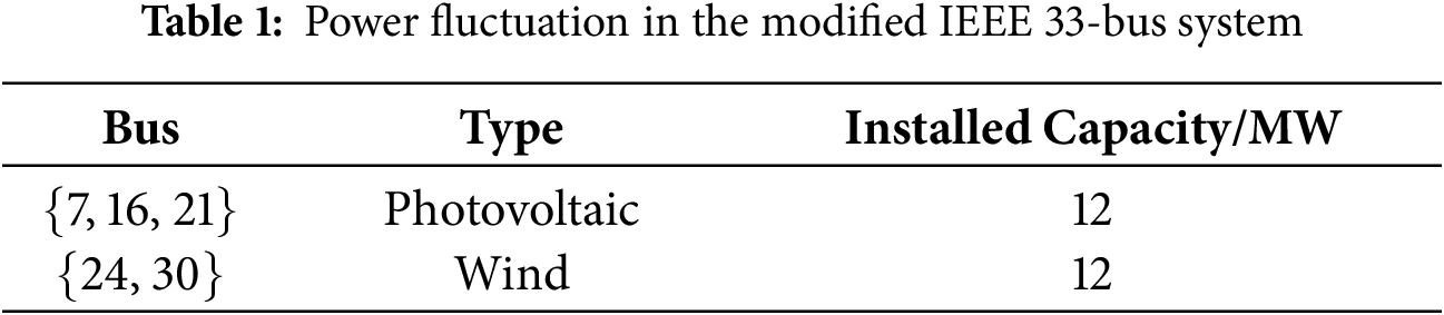
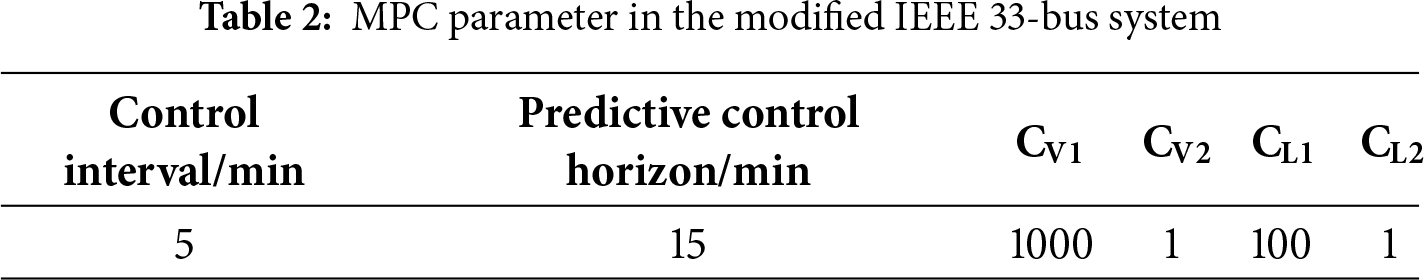
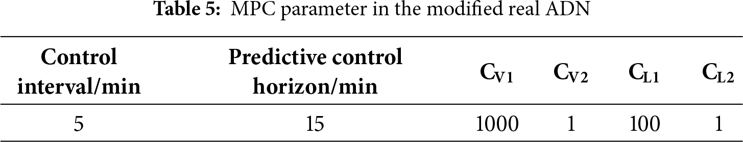
The modified IEEE 33-bus system as illustrated in Fig. 3. As shown, the system features a non-radial network structure with all tie-lines in service. The bus set {1, 2, …, 33} is the original system load bus, with bus 7, 16, and 21 connected to wind generator units, and bus 24 and 30 connected to photovoltaic units. Tie-lines are installed between the following bus sets {9, 15}, {8, 21}, {12, 22}, {25, 29}, and {18, 33}, and all of these tie-lines are energized, maintaining a meshed operational topology. The power fluctuations of the intraday photovoltaic, wind and system load are set referencing the data for 07 March 2023, in the Belgium region [34–36]. The secure voltage range for each bus in ADN is [0.95, 1.05] p.u., with a reference voltage set at 1.0 p.u. The parameters of renewable energy devices in the system are shown in Table 1. The MPC in this paper is focused on real-time voltage control within a control interval of 5 min and a predictive control horizon of 15 min. Regarding the weight coefficient settings in the MPC control objective function, to ensure effective control of voltage correction and network loss optimization, the weight coefficients for the voltage deviation part and the network loss optimization part are much larger than those for the control cost part. In the voltage correction control process, the ratio of weight between the voltage deviation part and the control cost part is set to 1000:1, while in the network loss optimization control process, the ratio of weight between the network loss part and the control cost part is set to 100:1. Refer to Table 2 for the specific MPC algorithm parameter settings.
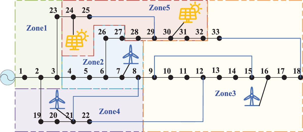
Figure 3: The modified IEEE 33-bus system
5.1.2 Koopman-WNN Sensitivity Analysis
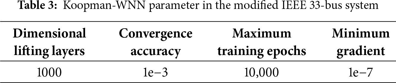
In this study, the wind power, solar power, and load power fluctuation data were configured based on operational datasets from the Belgium region spanning the years 2020 to 2023, which inherently contain measurement noise. Power flow calculations were then performed on this noisy dataset to build the historical operational database. Subsequently, 70% of the database was employed as the training set for Koopman-WNN, with 15% of the data allocated for validation and the remaining 15% for testing purposes. The active power and reactive power of each node are utilized as inputs, while voltage magnitude and phase angle are used as outputs, to regress the power flow equation. Similarly, employing the active power and reactive power of each node as inputs and network loss as output, the network loss equation is regressed. The training procedure involved iterative training using the conjugate gradient method. The relevant training parameters for the network are outlined in Table 3.
The accuracy of the Koopman-WNN model’s voltage sensitivity and network loss sensitivity is assessed by comparing its results with those derived from the physical model (assuming its absolute accuracy). Define the Root Mean Square Error (RMSE) and Mean Absolute Error (MAE) as the evaluation metric for testing precision.
where l and r present the number of rows and columns in the regression dataset; yij is the data in the ith row and jth column of the regression dataset;
The accuracy of voltage sensitivity analysis for 288 control sections within a day is assessed using RMSE, as depicted in Fig. 4. The regression accuracy of network loss sensitivity for 288 control sections within a day is evaluated using RMSE between its values obtained through sensitivity analysis and those computed via perturbation method (a prevalent approach), as illustrated in Fig. 5.
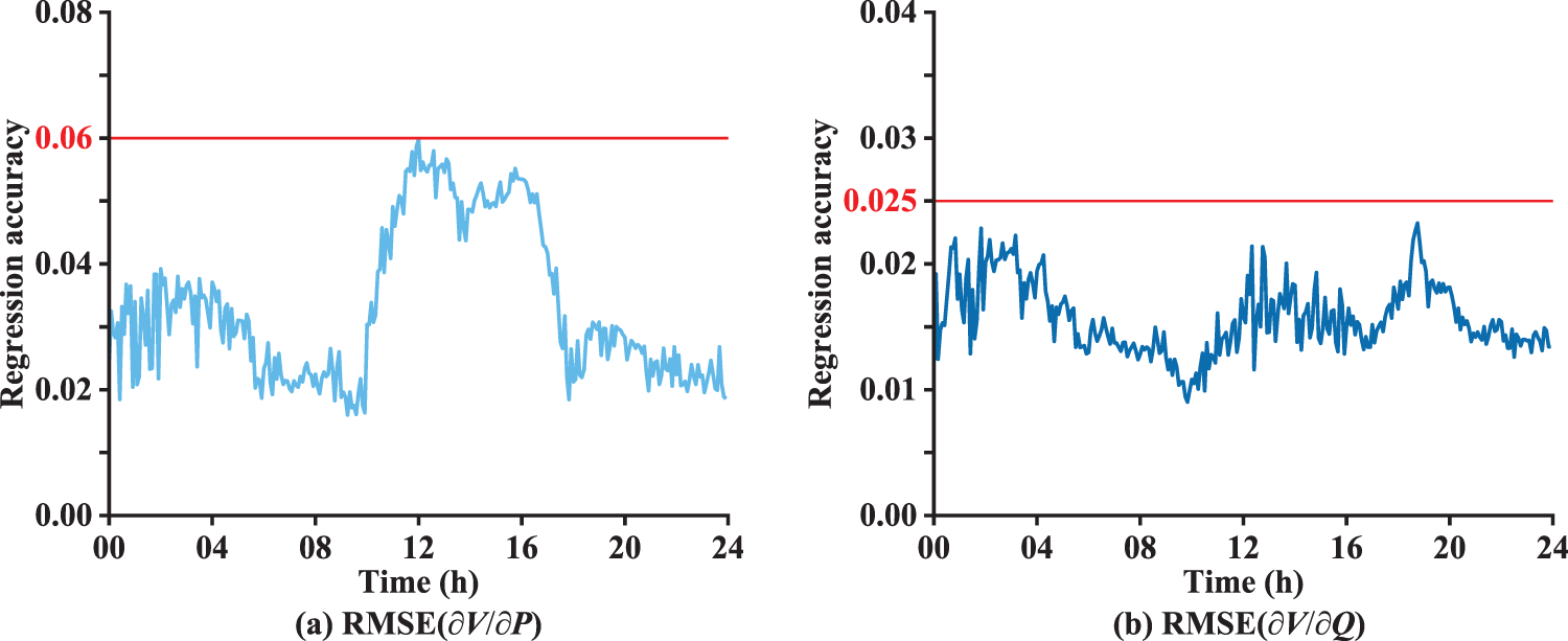
Figure 4: The voltage sensitivity regression accuracy
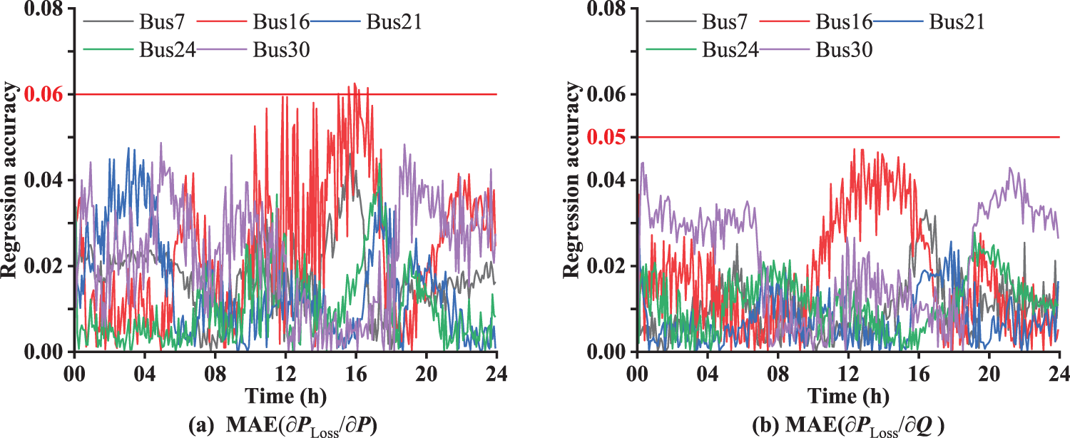
Figure 5: The network loss sensitivity regression accuracy
As shown in Fig. 4, within the 288 control sections through the day, the RMSE of voltage active sensitivity is within the range of [0, 0.06], and the RMSE of voltage reactive sensitivity is within the range of [0, 0.025], meeting the precision requirements of the voltage control. Fig. 5 reveals that, within each control section throughout the day, the MAE of active power loss sensitivity and reactive power loss sensitivity for the system’s various control resources lies within the range of [0, 0.06] and [0, 0.05], respectively, meeting the requirements of loss optimization control. Utilizing the data-driven Koopman-WNN linearized model, a real-time sensitivity analysis of system voltage and network losses is performed, demonstrating a high level of accuracy overall. This provides a robust basis for subsequent activities such as voltage correction and network loss optimization.
In response to the current issue of voltage violations in ADNs, this study proposes three MPC-based voltage control strategies, stemming from control framework and control modes:
(a) Distributed cooperative control: This strategy is designed for the dynamic partitioning structure within the ADN. It establishes a voltage-stratified distributed cooperative control that integrates the dual-mode adaptive switching, considering both system-wide network loss optimization and voltage correction as discussed earlier.
(b) Decentralized control: This strategy is designed for the dynamic partitioning structure within the ADN. It establishes a local autonomous control, enabling adaptive switching of control objectives between voltage correction and network loss optimization based solely on local voltage information, with no information exchange between regions.
(c) Constant voltage control: This strategy is designed for the dynamic partitioning structure within the ADN. It establishes a voltage layering distributed cooperative control strategy that only considers the voltage regulation control objectives for the system.
Fig. 6 depicts a comparative analysis of the voltage operating conditions of the system in the power fluctuation scenario under without control and with the implementation of the three aforementioned control strategies. Fig. 7 presents a comparison of daily network losses under distributed coordinated control and voltage regulation control.
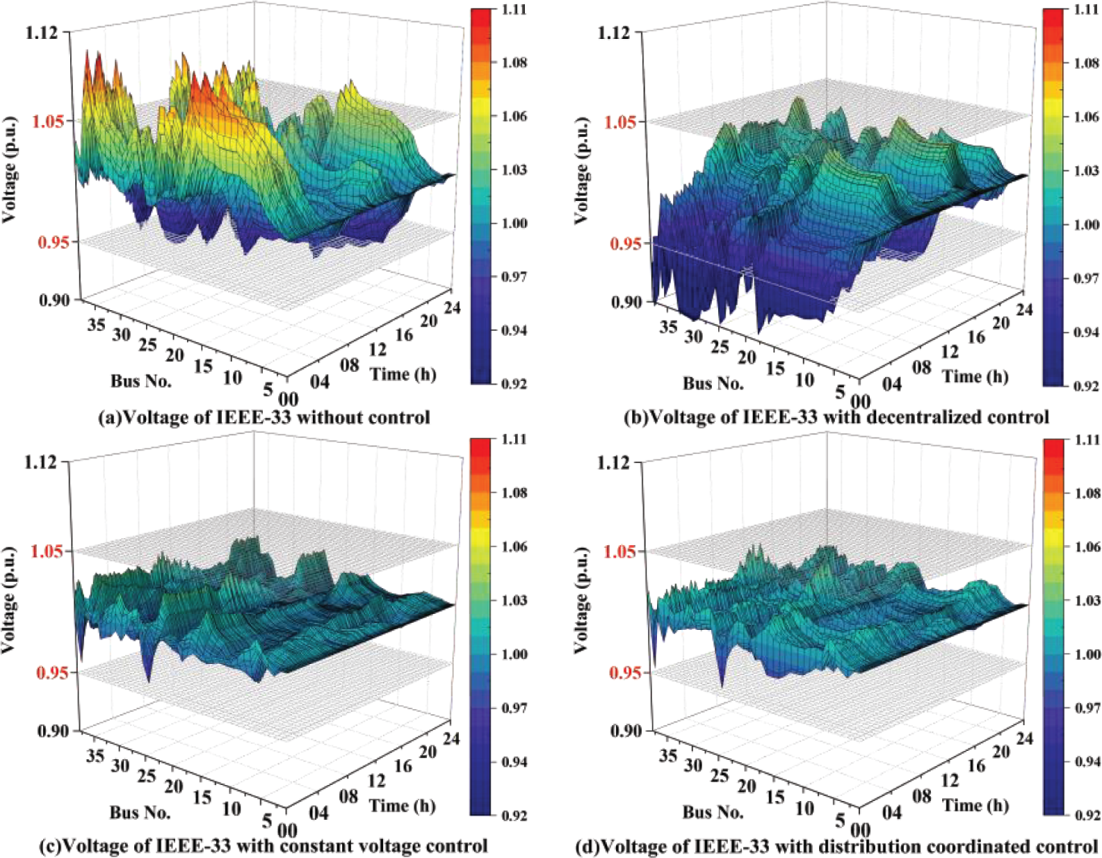
Figure 6: Voltage under different control strategies in the IEEE 33-bus system
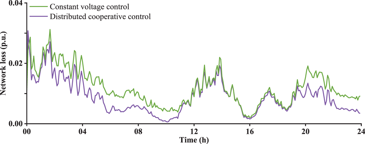
Figure 7: Network loss under different control strategies in the IEEE 33-bus system
This study evaluates control effectiveness based on the fundamental principle of ensuring that the voltages at all nodes in the system meet safety operational requirements while minimizing overall grid losses for superior control performance. In Fig. 6a, it is observed that under the fluctuating power scenario of renewable energy, severe bidirectional voltage violations occur at various nodes throughout the day. The implementation of decentralized control in this scenario, as shown in Fig. 6b, reveals that individual zones operate autonomously, lacking coordination in control measures, leading to excessive control due to interzone coupling and resulting in reverse voltage violations. Through the application of constant voltage control and distributed cooperative control, as depicted in Fig. 6c,d, it is evident that control measures for various system zones are coordinated and optimized by the control decision layer. As a result, voltages at all nodes in the system can operate within a safe range throughout the day. Furthermore, as indicated in the comparative chart of daily grid losses in Fig. 7, constant voltage control aims to minimize voltage deviations during the day, without fully considering the economic aspects of voltage operation. This approach leads to the utilization of reactive power resources for voltage correction even when voltages are within safe limits, resulting in higher grid losses compared to distributed cooperative control. The distributed cooperative control, employing ‘intra-zone dual-mode control’ and ‘inter-zone coordinated control’, achieves optimal control effects by meeting voltage safety requirements while reducing overall system grid losses. The underlying MPC framework, with an average computation time of about 1.6 s, demonstrates practical applicability in real-time grid operation, ensuring control efficiency.
5.2 The Caracas ADN Test System
5.2.1 Construction of the System and Operating Scenarios
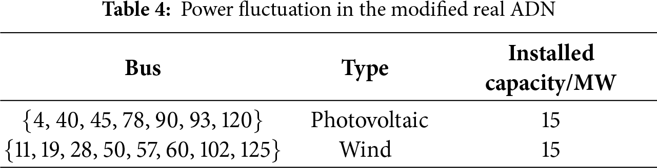
The modified ADN in the Caracas Metropolitan Area as illustrated in Fig. 8. This system operates as a non-radial network with all tie-lines energized. The bus set {1, 2, …, 141} is the original system load bus, with bus set {11, 19, 28, 50, 57, 60, 102, 125} connected to wind generator units, and bus set {4, 40, 45, 78, 90, 93, 120,} connected to photovoltaic units. Tie-lines are installed and maintained in service between the following bus sets {3, 105}, {22, 130}, {24, 85}, {38, 68}, {54, 115}, {74, 81}, and {95, 122}, ensuring a fully interconnected grid structure. The power fluctuations of the intraday photovoltaic, wind and system load are set referencing the data for 07 March 2023, in the Belgium region. The parameters of renewable energy devices in the system are shown in Table 4. Refer to Table 5 for the MPC algorithm parameter settings.
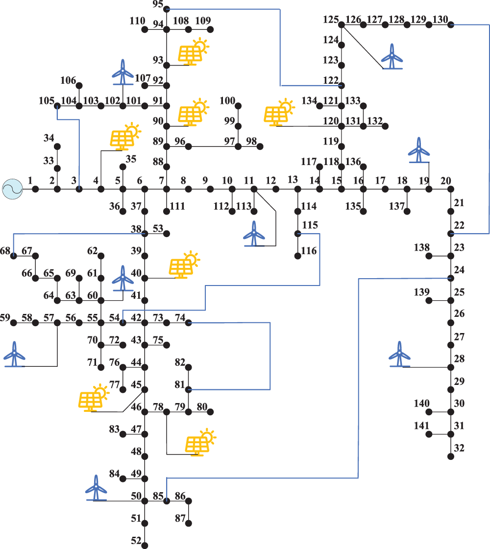
Figure 8: The modified real ADN in the Caracas Metropolitan Area
5.2.2 Koopman-WNN Sensitivity Analysis
This case study also adopts wind, solar, and load data from the Belgium region for the years 2020 to 2023. The operational parameters of the modified distribution network in the Caracas Metropolitan Area are configured, and a running database is generated. Subsequently, the linear regression method for the power flow equations and network loss equations is employed, following the training approach of the Koopman-WNN model used in the IEEE 33-bus system. The relevant training network parameters are set as shown in Table 6.

Utilizing the aforementioned linear regression model for the sensitivity analysis of system voltage and network loss, the analytical accuracy is evaluated using RMSE and MAE, as illustrated in Figs. 9 and 10. According to Fig. 9, within the 288 regulation sections throughout the day, the RMSE of active sensitivity for voltage falls within the range [0, 0.05], while the RMSE of reactive sensitivity for voltage is within the range [0, 0.02]. The precision meets the requirements of the voltage regulation system. Fig. 10 indicates that for each control section throughout the day, the MAE of active network loss sensitivity and reactive network loss sensitivity for various control resources in the system are within the regions [0, 0.025] and [0, 0.06], respectively, aligning with the demands of network loss optimization control.
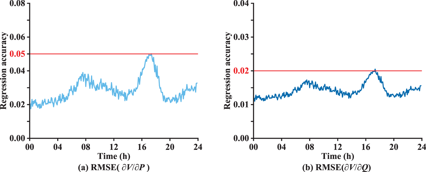
Figure 9: The voltage sensitivity regression accuracy
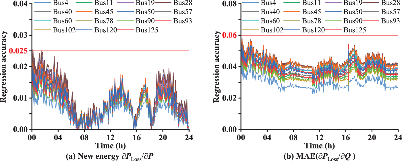
Figure 10: The network loss sensitivity regression accuracy
This case study also employs the previously mentioned decentralized control, constant voltage control, and distributed cooperative control for voltage regulation in the power grid. Fig. 11 provides a comparative illustration of the system voltage performance under various control strategies. Fig. 12 presents a comparative analysis of daily network loss between distributed coordination control and constant voltage control.
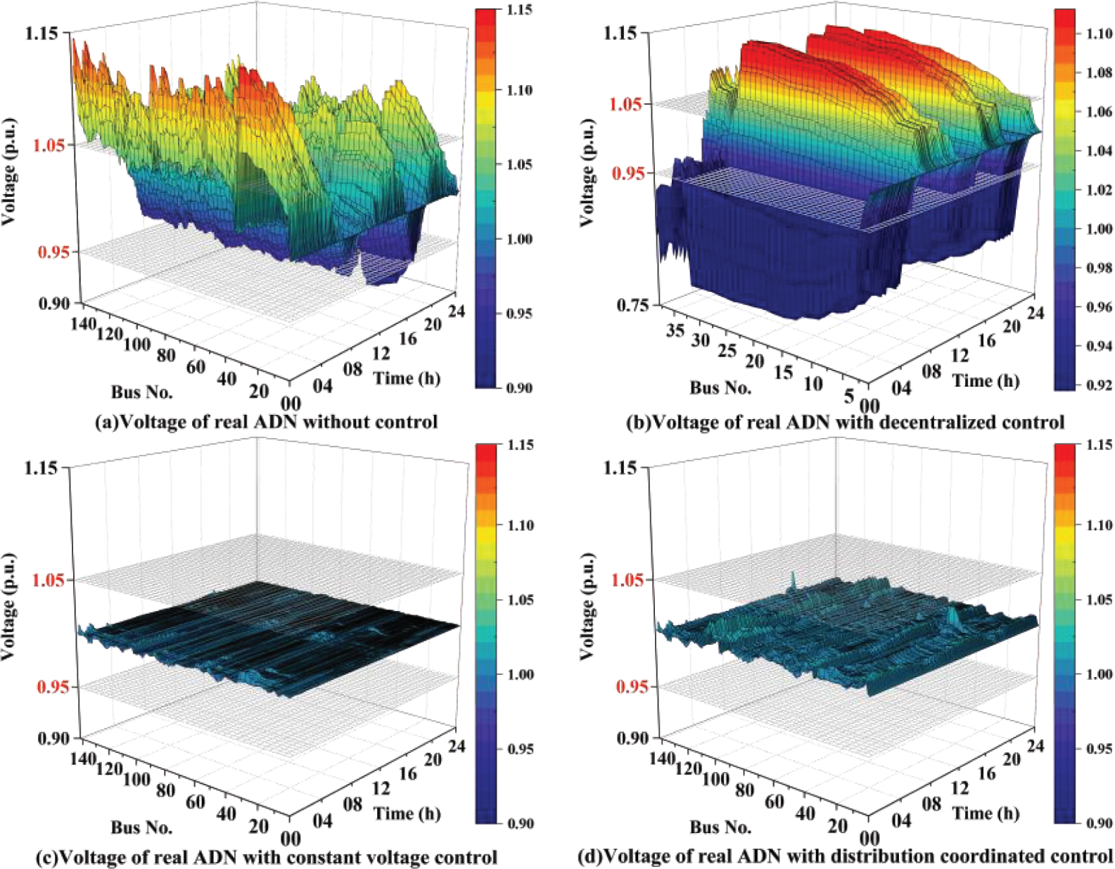
Figure 11: Voltage under different control strategies in the real ADN
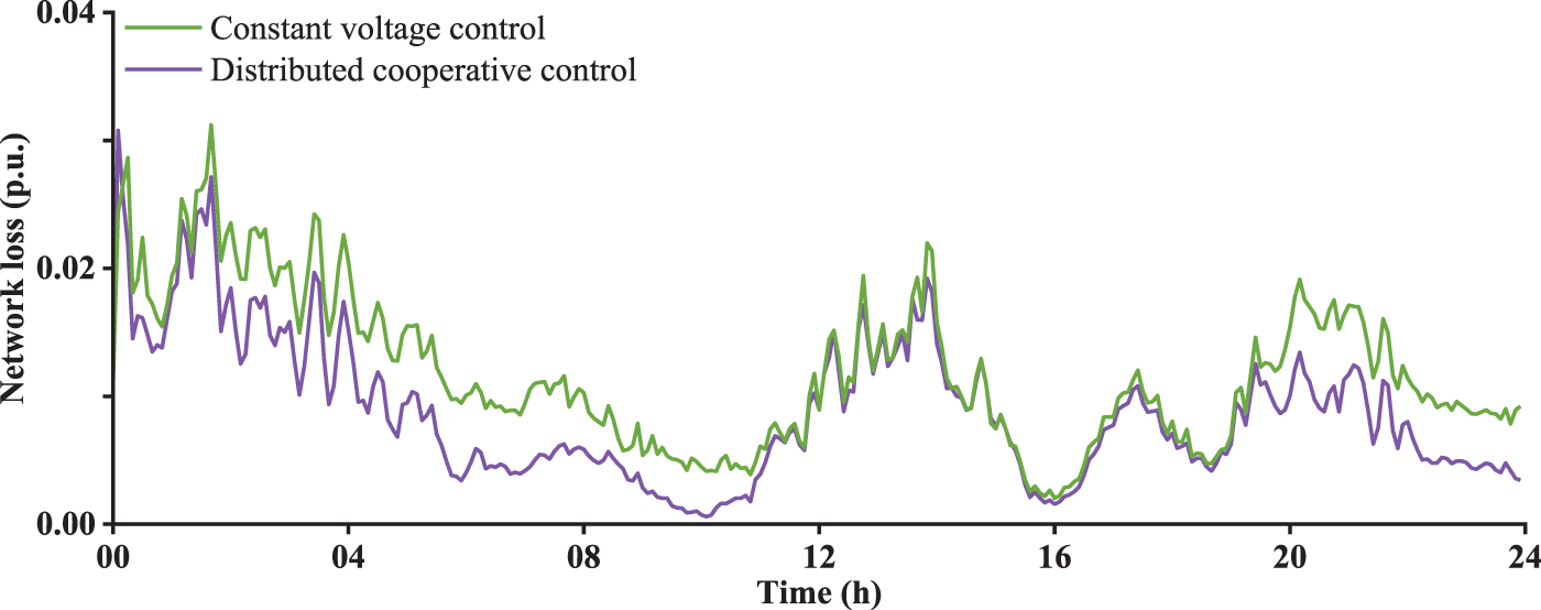
Figure 12: Network loss under different control strategies in the real ADN
In Fig. 11a, it can be observed that severe bidirectional overvoltage phenomena occur in the daily operation of the system when large-scale distributed renewable energy generation is integrated into the ADN. Upon implementing decentralized control for the system, as depicted in Fig. 11b, a phenomenon of serious over-control arises due to mutual influences among multiple regions, which may lead to the collapse of the power grid. In contrast, employing constant voltage control and distributed coordinated control, as shown in Fig. 11c,d, stabilizes the system voltage within the vicinity of 1.0 p.u. under the coordinated action of the control decision layer across multiple regions. Furthermore, based on the system daily network loss comparison chart in Fig. 12, it is evident that under the distributed coordinated control, the system network loss is superior to that under constant voltage control, attributed to the dual-mode adaptive switching mechanism. Therefore, in the complex ADN with large-scale integration of new energy sources, adopting distributed coordinated control efficiently utilizes reactive power resources, maintains voltage stability at approximately 1.0 p.u. in the neighboring domain, simultaneously reduces system network losses, and enhances the operational safety and economic efficiency of the system. With an average computation time of about 2.1 s for the MPC model, this approach successfully enhances both operational safety and economic efficiency of the system.
Simulation results for ADN demonstrate the effectiveness of the proposed strategy, leading to the following conclusions:
(a) The ‘Physics-Based Partitioning, Algorithmic Hierarchies’ coordinated control framework proposed in this paper achieves effective coordination of reactive power control resources across various regions, realizing global voltage control through autonomous state monitoring at the monitoring layer and collaborative control decision-making at the control decision layer. This control framework demonstrates significant advantages in addressing the distributed solution of large-scale active distribution networks.
(b) The control concept of adaptive switching in the proposed voltage correction and network loss optimization control model in this paper is based on daily adaptive switching of control objectives using local voltage information. This approach, while ensuring the safe operation of the system voltage, effectively reduces network losses and enhances the economic efficiency of the system.
(c) The proposed Koopman-WNN high-dimensional linearization model in this paper, driven by data, can effectively linearly regress the power flow equations and network loss equations, achieving high-precision sensitivity analysis of the system on a daily basis. This model holds significant advantages in supporting the construction and rapid solution of linear models for large-scale complex control systems.
In summary, the proposed control strategy in this paper demonstrates significant effectiveness in addressing voltage overlimit issues under the complex topology of ADN. This strategy reliably controls the voltage of each node within a safe range, reduces operational network losses, and enhances the overall safety and economic efficiency of the system. In future work, we will further investigate coordinated voltage regulation strategies involving both transmission and distribution networks.
Acknowledgement: Not applicable.
Funding Statement: This work was supported by the Science and Technology Project of State Grid Jiangsu Electric Power Co., Ltd. (J2024162).
Author Contributions: The authors confirm contribution to the paper as follows: Conceptualization, Wenfei Yi and Hao Yang; methodology, Wenfei Yi; validation, Wenfei Yi, Mingzhong Zheng and Jiayi Wang; formal analysis, Hao Yang; investigation, Mingzhong Zheng; resources, Mingzhong Zheng; data curation, Hao Yang; writing—original draft preparation, Jiayi Wang; writing—review and editing, Hao Yang; visualization, Jiayi Wang; supervision, Zhenglong Sun; project administration, Wenfei Yi; funding acquisition, Wenfei Yi and Mingzhong Zheng. All authors reviewed the results and approved the final version of the manuscript.
Availability of Data and Materials: Due to the nature of this research, participants of this study did not agree for their data to be shared publicly, so supporting data is not available.
Ethics Approval: Not applicable.
Conflicts of Interest: The authors declare no conflicts of interest to report regarding the present study.
References
1. Karimi M, Mokhlis H, Naidu K, Uddin S, Bakar AHA. Photovoltaic penetration issues and impacts in distribution network—a review. Renew Sustain Energy Rev. 2016;53:594–605. doi:10.1016/j.rser.2015.08.042. [Google Scholar] [CrossRef]
2. Hong L, Gao Y, Wu M, Xu C, Wu S, Du A. Optimization strategy for PV-hydrogen coordination in PV high-penetration distribution networks considering transformer lifetime consumption. Int J Hydrogen Energy. 2025;165:150688. doi:10.1016/j.ijhydene.2025.150688. [Google Scholar] [CrossRef]
3. Huang S, Zhang J, Lyu Z, Bai X. Research on data-driven combined network reconfiguration and local control with smart inverter for voltage regulation problem. Energy Rep. 2025;13:2000–12. doi:10.1016/j.egyr.2025.01.051. [Google Scholar] [CrossRef]
4. Hu R, Wang W, Wu X, Chen Z, Jing L, Ma W, et al. Coordinated active and reactive power control for distribution networks with high penetrations of photovoltaic systems. Sol Energy. 2022;231:809–27. doi:10.1016/j.solener.2021.12.025. [Google Scholar] [CrossRef]
5. Zeng F, Han H, Miao H, Pan Y, Yuan X, Lyu S. Multi-stage voltage control optimization strategy for distribution networks considering active-reactive co-regulation of electric vehicles. Energy Eng. 2025;122(1):221–42. doi:10.32604/ee.2024.056380. [Google Scholar] [CrossRef]
6. IEEE Std 1547-2018. IEEE standard for interconnection and interoperability of distributed energy resources with associated electric power systems interfaces. New York, NY, USA: IEEE Standards Association; 2018. [Google Scholar]
7. Nakadomari A, Krishnan N, Hemeida AM, Takahashi H, Omine E, Senjyu T. Coordinated voltage control of three-phase step voltage regulators and smart inverters to improve voltage profile and energy efficiency in unbalanced distribution networks. Energy Rep. 2023;9:234–41. doi:10.1016/j.egyr.2023.04.277. [Google Scholar] [CrossRef]
8. Song G, Wu Q, Jiao W, Lu L. Distributed coordinated control for voltage regulation in active distribution networks based on robust model predictive control. Int J Electr Power Energy Syst. 2025;166:110529. doi:10.1016/j.ijepes.2025.110529. [Google Scholar] [CrossRef]
9. Cagnano A, De Tuglie E. Centralized voltage control for distribution networks with embedded PV systems. Renew Energy. 2015;76:173–85. doi:10.1016/j.renene.2014.11.015. [Google Scholar] [CrossRef]
10. Maharjan S, Khambadkone AM, Peng JC. Robust constrained model predictive voltage control in active distribution networks. IEEE Trans Sustain Energy. 2021;12(1):400–11. doi:10.1109/TSTE.2020.3001115. [Google Scholar] [CrossRef]
11. Rahman DM, Ganguly S. Voltage regulation and energy loss minimization for distribution networks with high photovoltaic penetration and EV charging stations using dual-stage model predictive control. Sustain Energy Grids Netw. 2024;40:101529. doi:10.1016/j.segan.2024.101529. [Google Scholar] [CrossRef]
12. Takayama S, Ishigame A. Autonomous decentralized control of distribution network voltage using reinforcement learning. IFAC-PapersOnLine. 2018;51(28):209–14. doi:10.1016/j.ifacol.2018.11.703. [Google Scholar] [CrossRef]
13. Li P, Ji H, Yu H, Zhao J, Wang C, Song G, et al. Combined decentralized and local voltage control strategy of soft open points in active distribution networks. Appl Energy. 2019;241:613–24. doi:10.1016/j.apenergy.2019.03.031. [Google Scholar] [CrossRef]
14. Klemets JRA, Degefa MZ. A distributed algorithm for controlling continuous and discrete variables in a radial distribution grid. IEEE Access. 2023;11:2488–99. doi:10.1109/access.2023.3234102. [Google Scholar] [CrossRef]
15. Li Z, Wu Q, Chen J, Huang S, Shen F. Double-time-scale distributed voltage control for unbalanced distribution networks based on MPC and ADMM. Int J Electr Power Energy Syst. 2023;145:108665. doi:10.1016/j.ijepes.2022.108665. [Google Scholar] [CrossRef]
16. Li P, Ji J, Ji H, Jian J, Ding F, Wu J, et al. MPC-based local voltage control strategy of DGs in active distribution networks. IEEE Trans Sustain Energy. 2020;11(4):2911–21. doi:10.1109/TSTE.2020.2981486. [Google Scholar] [CrossRef]
17. Xiong W, Tang Z, Cui X. Distributed data-driven voltage control for active distribution networks with changing grid topologies. Control Eng Pract. 2024;147:105933. doi:10.1016/j.conengprac.2024.105933. [Google Scholar] [CrossRef]
18. Sun X, Qiu J, Tao Y, Ma Y, Zhao J. Coordinated real-time voltage control in active distribution networks: an incentive-based fairness approach. IEEE Trans Smart Grid. 2022;13(4):2650–63. doi:10.1109/TSG.2022.3162909. [Google Scholar] [CrossRef]
19. Zhang Z, Li P, Ji H, Zhao J, Xi W, Wu J, et al. Combined central-local voltage control of inverter-based DG in active distribution networks. Appl Energy. 2024;372:123813. doi:10.1016/j.apenergy.2024.123813. [Google Scholar] [CrossRef]
20. Zhang C, Xu Y. Hierarchically-coordinated voltage/VAR control of distribution networks using PV inverters. IEEE Trans Smart Grid. 2020;11(4):2942–53. doi:10.1109/TSG.2020.2968394. [Google Scholar] [CrossRef]
21. Tang W, Huang Y, Qian T, Wei C, Wu J. Coordinated central-local control strategy for voltage management in PV-integrated distribution networks considering energy storage degradation. Appl Energy. 2025;389:125684. doi:10.1016/j.apenergy.2025.125684. [Google Scholar] [CrossRef]
22. Ma W, Wang W, Chen Z, Wu X, Hu R, Tang F, et al. Voltage regulation methods for active distribution networks considering the reactive power optimization of substations. Appl Energy. 2021;284:116347. doi:10.1016/j.apenergy.2020.116347. [Google Scholar] [CrossRef]
23. Chai Y, Liang T, Dong Y, Zhao X, Lv C. Local-coordinated voltage optimal control strategy of integrated PV and ESS system in distribution networks with π-type network simplification. Electr Power Syst Res. 2024;231:110350. doi:10.1016/j.epsr.2024.110350. [Google Scholar] [CrossRef]
24. Dutta A, Ganguly S, Kumar C. MPC-based coordinated voltage control in active distribution networks incorporating CVR and DR. IEEE Trans Ind Appl. 2022;58(4):4309–18. doi:10.1109/TIA.2022.3163108. [Google Scholar] [CrossRef]
25. Escobar F, Pierrou G, Valverde G, Hug G. Data-driven participation of active distribution networks in transmission voltage control. Sustain Energy Grids Netw. 2025;43:101906. doi:10.1016/j.segan.2025.101906. [Google Scholar] [CrossRef]
26. Li P, Shen J, Wu Z, Yin M, Dong Y, Han J. Optimal real-time Voltage/Var control for distribution network: droop-control based multi-agent deep reinforcement learning. Int J Electr Power Energy Syst. 2023;153:109370. doi:10.1016/j.ijepes.2023.109370. [Google Scholar] [CrossRef]
27. Sun X, Qiu J. A customized voltage control strategy for electric vehicles in distribution networks with reinforcement learning method. IEEE Trans Ind Inform. 2021;17(10):6852–63. doi:10.1109/TII.2021.3050039. [Google Scholar] [CrossRef]
28. Zhang B, Cao D, Hu W, Ghias AMYM, Chen Z. Physics-Informed Multi-Agent deep reinforcement learning enabled distributed voltage control for active distribution network using PV inverters. Int J Electr Power Energy Syst. 2024;155:109641. doi:10.1016/j.ijepes.2023.109641. [Google Scholar] [CrossRef]
29. Koopman BO. Hamiltonian systems and transformation in Hilbert space. Proc Natl Acad Sci U S A. 1931;17(5):315–8. doi:10.1073/pnas.17.5.315. [Google Scholar] [PubMed] [CrossRef]
30. Choi H, Elliott R, Trudnowski D, Venkat D. Transient stability quantification of power systems with inverter-based resources via Koopman operator based machine learning approach. Electr Power Syst Res. 2024;237:111035. doi:10.1016/j.epsr.2024.111035. [Google Scholar] [CrossRef]
31. Zhou J, Jia Y, Yong P, Liu Z, Sun C. Robust deep Koopman model predictive load frequency control of interconnected power systems. Electr Power Syst Res. 2024;226:109948. doi:10.1016/j.epsr.2023.109948. [Google Scholar] [CrossRef]
32. Guo L, Zhang Y, Li X, Wang Z, Liu Y, Bai L, et al. Data-driven power flow calculation method: a lifting dimension linear regression approach. IEEE Trans Power Syst. 2022;37(3):1798–808. doi:10.1109/TPWRS.2021.3112461. [Google Scholar] [CrossRef]
33. Khodr HM, Olsina FG, De Oliveira-De Jesus PM, Yusta JM. Maximum savings approach for location and sizing of capacitors in distribution systems. Electr Power Syst Res. 2008;78(7):1192–203. doi:10.1016/j.epsr.2007.10.002. [Google Scholar] [CrossRef]
34. Elia. Load and load forecast [Internet]. Brussels, Belgium: Elia Group. 2024 [cited 2024 Sep 20]. Available from: https://www.elia.be/en/grid-data/load-and-load-forecasts. [Google Scholar]
35. Elia. Wind power generation [Internet]. Brussels, Belgium: Elia Group. 2024 [cited 2024 Sep 20]. Available from: https://www.elia.be/en/grid-data/generation-data/wind-power-generation. [Google Scholar]
36. Elia. Solar power generation [Internet]. Brussels, Belgium: Elia Group. 2024 [cited 2024 Sep 20]. Available from: https://www.elia.be/en/grid-data/generation-data/solar-power-generation. [Google Scholar]
Cite This Article
 Copyright © 2026 The Author(s). Published by Tech Science Press.
This work is licensed under a Creative Commons Attribution 4.0 International License , which permits unrestricted use, distribution, and reproduction in any medium, provided the original work is properly cited.
 Downloads
 Citation Tools