
 Submit a Paper
 Propose a Special lssue
 Open Access
ARTICLE

Safe and Explainable Reinforcement Learning-Based Intelligent Switching Control for Standalone and Grid-Tied Z-Source Inverter under Uncertain Solar Conditions
1 Department of Electrical Engineering, Central Institute of Technology, Kokrajhar, Assam, India
2 Department of Instrumentation Engineering, Central Institute of Technology, Kokrajhar, Assam, India
3 Department of Electronics and Instrumentation Engineering, National Institute of Technology, Chümoukedima, Dimapur, Nagaland, India
* Corresponding Author: Biswanath Hajoary. Email:
Energy Engineering 2026, 123(7), 20 https://doi.org/10.32604/ee.2026.075305
Received 29 October 2025; Accepted 04 February 2026; Issue published 18 June 2026
 View Full Text
 Download PDF
Abstract
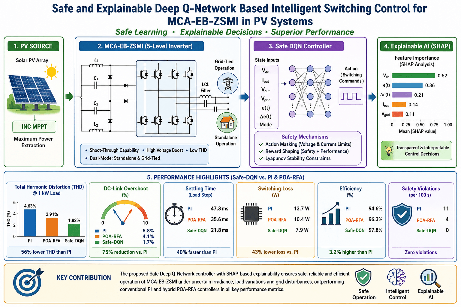
The increasing integration of photovoltaic systems into smart grids requires accurate evaluation of power conversion efficiency and output performance. In this context, Z Source Multilevel Inverters function as voltage boosting converters and offer a certain degree of fault tolerance. However, conventional control strategies such as proportional integral controllers and hybrid optimization-based methods including POA-RFA (Pelican Optimization Algorithm-Random Forest Algorithm) are limited in their ability to maintain dynamic stability, efficiency, and operational safety under varying solar irradiance and load conditions. This study proposes a safe and explainable Deep Q Network based intelligent switching control framework for the Modified Capacitor Assisted Extended Boost Z Source Multilevel Inverter operating in both standalone and grid tied modes. A unified reinforcement learning controller is designed to ensure effective voltage regulation, strict enforcement of safety constraints, and transparent decision making through SHAP (SHapley Additive exPlanations) based interpretability. Simulation results demonstrate that the proposed Safe DQN (Safety-Aware Deep Q-Network) controller achieves a total harmonic distortion of 1.63 percent and an efficiency of 97.8 percent without any safety violations across diverse operating scenarios. In addition, it provides 40 percent faster settling time and 50 percent lower switching losses compared to proportional integral and POA RFA controllers. Explainability analysis confirms that the control decisions are consistent with the underlying physical dynamics of the system. Overall, this work advances safe, adaptive, and interpretable control strategies for renewable energy converters suitable for real time intelligent power electronic applications.Graphic Abstract
Keywords
With the advancement of renewable energy technologies, solar photovoltaic systems have become a key component of distributed power generation. These systems are mainly deployed in two operating modes, namely standalone and grid tied configurations. Standalone photovoltaic systems operate independently of the utility grid and are commonly used in remote areas with isolated load requirements. Their performance strongly depends on efficient power management, particularly under rapidly varying environmental conditions such as changes in solar irradiance and temperature [1].
In contrast, grid tied photovoltaic systems operate in coordination with the main electrical grid. These systems must maintain synchronization with the grid voltage and frequency and ensure smooth operation during islanding events as well as during grid reconnection. In both operating modes, the effectiveness of the system is largely determined by how efficiently solar energy is converted into usable alternating current power [2,3].
This energy conversion process is typically achieved using power electronic inverters, which are responsible for voltage boosting, waveform shaping, and reactive power control. Among various inverter topologies, Z-Source Multilevel Inverters are recognized for their ability to perform both voltage step up and step down operations within a single power conversion stage [4]. This characteristic improves overall system efficiency and reliability. Due to their tolerance to shoot through states, strong voltage boosting capability, and enhanced output waveform quality, these inverters are well suited for solar photovoltaic applications [5].
1.2 Role and Challenge of Switching Control in ZSMIs
Despite their structural advantages, Z-Source Multilevel Inverters introduce considerable complexity in control design, mainly due to their nonlinear and time varying characteristics. The switching strategy must ensure accurate voltage regulation, low harmonic distortion, and fast dynamic response to disturbances such as load changes, variations in solar irradiance, and grid related fluctuations. Conventional control methods, particularly proportional integral controllers, are widely used but often prove inadequate for such systems because of their limited adaptability and inherent linear structure [6,7].
To address nonlinear behavior, fuzzy logic-based control schemes have been explored to improve performance. However, these approaches rely heavily on expert knowledge and predefined rules, which restrict their scalability and effectiveness across a wide range of operating conditions. In an effort to overcome these limitations, hybrid optimization-based techniques, such as the Penguin Optimization Algorithm combined with the Red Fox Algorithm, have been proposed for inverter control applications. These methods offer improvements in parameter tuning and adaptive capability, but they still face challenges in ensuring robust and consistent performance [8].
The conceptual control framework is illustrated in Fig. 1 and consists of a photovoltaic module, a Modified Capacitor Assisted Extended Boost Z Source Multilevel Inverter, and a load or grid interface connected through a closed loop control structure governed by a Safe Deep Q Network (Safe DQN) agent. System states, including DC link voltage, grid conditions, and current ripple, are provided as inputs to the agent. The agent processes these inputs through a neural network, enforces safety constraints, and selects appropriate switching actions for the inverter. At the same time, an explainable artificial intelligence module evaluates and interprets the control decisions using SHAP based visual analysis, thereby improving transparency and operator understanding [9,10].

Figure 1: Architecture of the Safe-DQN and explainable control framework.
1.3 Motivation for DQN, Safe Reinforcement Learning, and XAI
To address these challenges, this work explores deep reinforcement learning, specifically Deep Q Networks, as an intelligent alternative for switching control in Z Source Multilevel Inverters. Deep reinforcement learning enables an agent to learn optimal control policies through continuous interaction with the operating environment. Unlike conventional controllers that depend on predefined mathematical models or fixed rule sets, a Deep Q Network (DQN) based agent improves its performance over time by learning from experience. This capability is particularly beneficial for controlling highly nonlinear systems such as Z-Source Multilevel Inverters under rapidly changing photovoltaic and grid conditions [11].
However, standard deep reinforcement learning approaches, including Deep Q Networks, primarily focus on maximizing cumulative reward and often neglect safety considerations during intermediate control actions. In power electronic systems, unsafe actions can lead to overvoltage conditions, component damage, or violations of grid codes, making safety a critical requirement rather than a secondary concern. This motivates the integration of Safe Reinforcement Learning principles into the control framework. Safe Reinforcement Learning modifies the conventional Deep Q Network by incorporating hard or soft safety constraints during both training and operation. These measures include reward shaping, action masking, and constraint learning based on Lyapunov stability theory, which collectively prevent the agent from selecting actions that could compromise inverter integrity or power quality [12].
Although Safe Reinforcement Learning enhances operational reliability, its internal decision-making process is often difficult to interpret, which limits its acceptance in real world applications. In regulated and safety critical domains such as power electronics, system operators and engineers must understand the rationale behind control actions. Explainable Artificial Intelligence addresses this requirement by providing transparent interpretation of the learning agent behavior. Techniques such as SHAP based feature attribution and saliency analysis make it possible to identify how input states, including photovoltaic voltage, current, and grid conditions, influence the controller decisions. By offering human understandable explanations, Explainable Artificial Intelligence fosters trust, enables fault diagnosis, supports certification processes, and strengthens safety validation.
1.4 Objectives and Contributions
This paper presents a unified control framework that combines Safe Deep Q-Network (Safe-DQN) reinforcement learning with XAI-based (Explainable Artificial Intelligence) interpretability for intelligent switching control of a Modified Capacitor-Assisted Extended Boost Z-Source Multilevel Inverter (MCA-EB-ZSMI). The framework is validated in both standalone and grid-tied operational modes under uncertain solar and load conditions.
Objectives of this work are as follows:
• Develop a Safe-DQN controller that enforces voltage and current constraints while learning optimal switching actions in real time.
• Integrate XAI modules to provide the visualization and interpretability of switching decisions, thus adding a layer of transparency in operations for safety assurance.
• Simulate proposed control scheme during several situations such as dynamic irradiance, islanding events, and load transients.
• Compare and evaluate the proposed method against the classical PI and hybrid POA-RFA controllers on several metrics, including THD, power efficiency, switching loss, and robustness.
To Demonstrate real-time implementation feasibility through an extensive MATLAB/Simulink-based training and performance analysis procedure.
The key contributions of this work are threefold. First, a safety-aware deep reinforcement learning–based intelligent switching controller is developed for a modified capacitor-assisted extended boost Z-source multilevel inverter operating under both standalone and grid-tied modes, explicitly embedding voltage and current constraints to ensure reliable operation under uncertain solar and load conditions. Second, an explainable artificial intelligence framework is integrated with the proposed Safe-DQN controller, enabling transparent interpretation of switching decisions through feature attribution analysis, thereby addressing trust and certification challenges associated with black-box learning-based controllers in power electronic systems. Third, a unified control architecture is validated through comprehensive MATLAB/Simulink simulations under dynamic irradiance, load transients, and grid disturbances, demonstrating superior performance over conventional PI and hybrid POA-RFA controllers in terms of harmonic distortion, voltage regulation, efficiency, and safety compliance.
2 Related Work and Research Gaps
2.1 Conventional Control Strategies for ZSMIs
The Z Source Multilevel Inverter uses an impedance network to achieve single stage DC voltage boosting and AC inversion, which makes it well suited for photovoltaic applications. Traditional control strategies mainly rely on proportional integral controllers because of their simplicity and ease of implementation. However, these linear controllers are not capable of handling the rapidly changing dynamics of photovoltaic systems, which can lead to degraded transient response and increased harmonic distortion [13].
To address system nonlinearities, fuzzy logic controllers have been introduced in inverter control. For instance, Sivakumar and Sumathi (2015) applied fuzzy sinusoidal pulse width modulation control to a cascaded multilevel inverter and achieved reduced total harmonic distortion in photovoltaic applications [14]. Although fuzzy logic controllers offer improved robustness, they typically depend on manually designed rule sets and heuristic based tuning, which limits their scalability and general applicability.
Hybrid metaheuristic control approaches, such as the Penguin Optimization Algorithm combined with the Red Fox Algorithm, integrate global optimization techniques with fuzzy systems to improve adaptability. However, these methods often involve high computational complexity, which restricts their suitability for real time control applications. Similarly, an FLC (Fuzzy Logic Controller)-PSO (Particle Swarm Optimization)-PI (Proportional–Integral) based hybrid controller demonstrated effective output voltage regulation in a five-level inverter under varying load conditions, but it did not explicitly address the dynamic effects of fluctuating solar irradiance and rapid load changes. Consequently, while conventional and hybrid control strategies show acceptable performance, they lack the ability to learn and adapt in real time under highly variable operating conditions.
2.2 AI and Machine Learning in Power Electronics
Recent studies have explored artificial intelligence and machine learning techniques, including artificial neural networks, convolutional neural networks, and reinforcement learning, for inverter control. For example, neural network augmented proportional integral controllers for eleven level inverters have demonstrated improved power quality in hybrid energy systems. However, these model-based or supervised learning approaches require large amounts of training data and often struggle to generalize under unforeseen operating conditions.
Reinforcement learning, particularly deep reinforcement learning, provides an online learning framework in which the agent adapts its control policy through continuous interaction with the environment. Although reinforcement learning remains relatively unexplored in inverter control, it has been successfully applied in related power system domains. In one study, safe reinforcement learning was applied to a two-level voltage source converter testbed, where the learned control strategies effectively maintained safety constraints (Wan et al., 2024). These results highlight the potential of reinforcement learning while also revealing the limited application of these methods to multilevel inverters, such as Z Source Multilevel Inverters, under real world environmental uncertainties [15].
2.3 Safe RL and Explainable AI (XAI) in Control Applications
Standard reinforcement learning algorithms do not inherently incorporate safety considerations and can behave unpredictably during exploration, which poses unacceptable risks in power electronic systems. To address this, safe reinforcement learning techniques, including action masking, reward shaping, and Lyapunov based constraints, are increasingly integrated into system models to enforce operational safety. Comprehensive surveys in smart grid applications (Yu et al., 2024; Bui et al., 2024) highlight the use of safety aware reinforcement learning for frequency regulation and voltage control. However, very few component level implementations exist, indicating that Safe RL has seen limited deployment in inverter level systems such as Z Source Multilevel Inverters [16,17].
Another limitation of reinforcement learning based controllers is their black box nature, which hinders acceptance in regulated power systems. Explainable artificial intelligence methods, such as SHAP, saliency mapping, and feature sensitivity analysis, provide tools to interpret the policies learned by RL agents. While XAI has been extensively studied in general AI literature, its integration with reinforcement learning for control applications is still in its early stages [18]. At present, there is limited research applying XAI to analyze and explain RL decision making in safety critical power electronic systems.
The comprehensive review of conventional, hybrid, and learning-based control strategies for Z-source multilevel inverters reveals several unresolved challenges that limit their applicability in modern photovoltaic systems operating under uncertainty. Despite extensive research on PI, fuzzy, and metaheuristic-assisted controllers, these methods primarily rely on offline tuning and fixed rule sets, which restrict their ability to adapt in real time to rapid irradiance fluctuations, load transients, and grid disturbances encountered in practical PV installations. This limitation becomes particularly critical in systems required to operate seamlessly in both standalone and grid-tied modes.
Recent advances in reinforcement learning have demonstrated promising adaptability in power system–level applications; however, their adoption at the converter and inverter control level remains sparse. Existing RL-based approaches largely focus on two-level converters or simplified voltage source inverters, leaving multilevel topologies such as ZSMIs underexplored. Moreover, most reported studies emphasize performance optimization without explicitly embedding safety constraints, thereby exposing the system to risks of over-voltage, over-current, and unstable switching behavior during exploration and learning phases.
Another major gap identified in the literature is the lack of systematic safety assurance mechanisms within RL (Reinforcement Learning)-based inverter controllers. While Safe Reinforcement Learning frameworks have been proposed at the grid or system level, their translation to component-level control particularly for multilevel inverters operating under uncertain solar conditions, which has not been sufficiently investigated. This absence of safety-aware learning limits the practical deployment of RL (Reinforcement Learning) controllers in safety-critical power electronic systems.
In addition, the opaque nature of reinforcement learning algorithms presents a significant barrier to their acceptance in regulated energy systems. Most existing RL-based inverter control strategies function as black-box solutions, offering little insight into the rationale behind switching decisions. The limited integration of explainable artificial intelligence techniques within inverter-level RL control frameworks prevents operators, designers, and regulators from validating and trusting learned control policies.
Finally, current studies typically address either standalone or grid-connected operation independently, with very limited work focusing on a unified control framework capable of managing both modes within a single learning architecture. This separation overlooks the operational reality of modern PV systems, which frequently transition between grid-tied and islanded conditions.
Addressing these gaps, the present work proposes a unified Safe-DQN-based intelligent switching control framework for a modified capacitor-assisted extended boost Z-source multilevel inverter operating in both standalone and grid-tied modes. The proposed approach embeds explicit voltage and current safety constraints within the reinforcement learning process, ensuring stable and reliable operation under uncertain solar irradiance and load variations. Furthermore, an explainable AI module based on SHAP analysis is integrated to interpret the learned switching decisions, thereby enhancing transparency, trust, and potential regulatory acceptance. Through comprehensive MATLAB/Simulink-based validation, the proposed framework demonstrates how safety-aware and interpretable reinforcement learning can effectively overcome the limitations of existing control strategies for advanced multilevel inverter-based PV systems.
Recent studies have increasingly explored soft-computing and metaheuristic-based optimization techniques for improving MPPT accuracy and inverter control performance in photovoltaic systems. Hybrid MPPT approaches combining classical algorithms with intelligent optimization have been shown to enhance tracking speed, reduce steady-state oscillations, and improve robustness under rapidly changing irradiance conditions [19]. In parallel, optimized PI and multilevel inverter control strategies using metaheuristic algorithms have demonstrated notable improvements in dynamic response, harmonic suppression, and performance indices such as the integral of time-weighted absolute error (ITAE) and integral of time-weighted squared error (ITSE). These studies highlight the growing relevance of intelligent optimization in both MPPT tracking and inverter control, providing a strong foundation for integrating reinforcement learning-based decision-making with safety-aware switching strategies in advanced multilevel inverter topologies [20].
3 System Modeling and Configuration
3.1 Modified Capacitor-Assisted Extended Boost Z-Source Multilevel Inverter (MCA-EB-ZSMI)
The Modified Capacitor-Assisted Extended Boost Z-Source Multilevel Inverter (MCA-EB-ZSMI) is created for a greater voltage gain and demonstrates multilevel waveform generation while providing better stability during fluctuation in solar conditions. The impedance network is formed using two inductors, namely
The boost factor of MCA-EB-ZSMI during the shoot-through period is characterized by the following equation [21]:
where
where
The shoot-through interval is very carefully scheduled to make sure that continuous operation happens, and in doing so, the effective voltage gain is increased while the stress on the switches is alleviated.
The selection of the multilevel inverter (MLI) configuration is a critical design decision that directly influences harmonic performance, switching losses, and controller complexity. In this study, a five-level MCA-EB-ZSMI topology is adopted as it offers an effective compromise between waveform quality and practical implement-ability. While higher-level MLIs (seven- or nine-level) can further reduce voltage THD, they require a significantly larger number of switching devices, gate drivers, and control states, leading to increased switching losses, higher computational burden, and more complex real-time decision spaces for reinforcement learning-based controllers. Conversely, lower-level configurations provide simpler control but suffer from higher harmonic distortion and larger output filter requirements. The five-level structure achieves sufficiently low THD with moderate switching frequency and reduced device stress, while maintaining a manageable action space suitable for Safe-DQN-based intelligent switching. This trade-off makes the selected inverter level well-suited for integrating safe reinforcement learning and explainable control strategies without compromising real-time feasibility.
3.2 Solar PV Modeling and MPPT Algorithm
The equivalent circuit of a single diode is employed to model the photovoltaic module. The voltage-current (I-V) output characteristics of the PV cell are given by the equation [23]:
here,
In order to harness the topmost power from the PV module under transient solar conditions, the Incremental Conductance (INC) Maximum Power Point Tracking (MPPT) algorithm is thus being implemented. The algorithm works on the principle that the derivative of power relative to voltage at its MPP equals zero, which is stated in equation below [24]:
By solving for the incremental condition, gives:
This state affects to regulate
3.3 Grid Integration and Islanding Detection Mechanism
There are two operational modes accepted by the system: standalone and grid-tied. When in grid-tied mode, it is essential that an inverter output is synchronized with the utility grid voltage phase
where
Over/under-voltage and over/under-frequency settings together serve for the detection of islanding condition. In selecting the islanding status, the inverter goes automatic-manual disconnection from the grid through a static switch and the facility offers autonomous mode. Later, the inverter supplies power to the local R-L load, keeping voltage and frequency decided through an intelligent RL-based control system.
The Fig. 2 illustrates the overall operational flow of the proposed photovoltaic power conversion system. Solar energy is processed through the PV array and regulated by the Incremental Conductance MPPT algorithm before feeding the impedance network of the MCA-EB-ZSMI. The inverter output is filtered and supplied to either standalone loads or the utility grid. The Safe-DQN controller continuously observes system states and generates optimal switching decisions, while the XAI module provides interpretability of control actions for enhanced transparency and reliability.

Figure 2: Flowchart of MCA-EB-ZSMI-based PV system with Safe-DQN control.
3.4 Switching Devices and Output Filtering
The Silicon Carbide (SiC) MOSFETs, particularly the C3M0120090D from Wolfspeed, are chosen as switching devices to be used in the inverter legs because of their very low switching losses and high tolerance to temperature. Each inverter leg contains a half-bridge module with antiparallel diodes to allow for bidirectional current flow.
To suppress harmonics and minimize Total Harmonic Distortion (THD), an LCL filter is employed at the output. The transfer function of the LCL filter is given by [26]:
where
3.5 System Configuration and Simulation Assumptions
The overall system is implemented in MATLAB/Simulink environment using Simscape Electrical with a fixed-step simulation of
The LCL filter is designed with

The electrical and modulation parameters of the proposed MCA-EB-ZSMI are explicitly defined to ensure reproducibility and clarity of implementation. The inverter operates at a fixed switching frequency of 10 kHz, selected as a compromise between switching loss and harmonic suppression. A sinusoidal pulse-width modulation scheme with embedded shoot-through states is adopted, where the modulation index is maintained within a safe operating range to prevent over-modulation and impedance network saturation. The DC-link voltage reference is set to 380 V for both standalone and grid-tied operation, enabling sufficient voltage margin for multilevel synthesis. The LCL output filter parameters are selected based on grid code compliance and resonance attenuation, ensuring low current ripple and reduced total harmonic distortion. The shoot-through duty ratio is adaptively regulated by the Safe-DQN controller and constrained within predefined limits to guarantee safe operation of the Z-source impedance network.
Fig. 3 shows the overall system configuration. It includes the PV array with MPPT, the MCA-EB-ZSMI circuit with impedance network and multilevel H-bridge, the SiC switching network, the LCL filter, the grid/load interface, and the Safe-RL controller loop. The Safe-RL agent receives real-time feedback and interacts with the inverter environment, while the XAI block provides interpretability for the switching decisions.

Figure 3: System architecture of MCA-EB-ZSMI with Safe-RL switching and MPPT integration.
4 Deep Reinforcement Learning-Based Controller Design
In this section, we present the formulation, architecture, and safety integration of the Deep Q-Network (DQN) controller applied for intelligent switching control in the MCA-EB-ZSMI. The controller is trained using a Reinforcement Learning (RL) paradigm, where an agent interacts with the inverter environment and learns to take optimal switching decisions. The learning process considered under the MDP framework enables the agent to infer behavior of the system from the environmental feedback and obtain maximum cumulative reward. The key design elements include the state-action-reward formulation, DQN agent architecture, and training along with the implementation of the Safe RL mechanisms which enforce operational constraints during learning and execution.
4.1 Markov Decision Process (MDP) Formulation
A Markov Decision Process is formally defined by a tuple
The discount factor γ determines the relative importance of future rewards in the control policy. In this study, γ was set to 0.99 to reflect the long-term and continuous nature of inverter operation, where voltage regulation, harmonic suppression, and safety enforcement must be maintained over extended time horizons rather than optimized for short-term transients. A high discount factor ensures that the agent prioritizes steady-state performance and long-term stability of the DC-link voltage and output waveforms. Preliminary simulations with lower γ values (0.90–0.95) resulted in faster transient responses but increased steady-state ripple and higher harmonic distortion, whereas γ = 0.99 provided the best trade-off between dynamic response and long-term performance.
The control problem is formulated as a Markov Decision Process (MDP), where the system state at time step
where
The error rate
The binary mode indicator which is
The inverter switching control is formulated as a discrete control problem where each action corresponds to a predefined inverter switching configuration. Given the MCA-EB-ZSMI structure, the system operates in one of four discrete modes: shoot-through (ST), positive output state, zero output state, or negative output state. Thus, the action space is defined as [30]:
here, with
4.1.3 Reward Function and Safety Constraints
The reward function is designed for encouraging voltage regulation, harmonic suppression, as well as safe operation. The reward
The expression has its first term with the deviation, penalizing departure from the reference voltage, via an absolute voltage error
where
To guarantee safe operation of the inverter during both training and execution, hard safety constraints are imposed on the DC-link voltage and inverter output current. Safety violations are triggered whenever the following conditions are satisfied [33]:
The maximum DC-link voltage limit
When a safety violation occurs, a large negative penalty is applied to the reward function to discourage unsafe actions [34]:
This strengthens the Safe-RL claim.
4.2 Deep Q-Network (DQN) Agent Design
The DQN algorithm approximates the optimal action-value function
The loss function is used to train the network which is known as the Huber loss defined as follows:
where the target value
here,
This formulation prevents exploding the gradients as well as ensures that the method is robust, even when there are large Q-value errors.
The input layer of the DQN consists of seven neurons, each corresponding to one element of the state vector defined previously, two hidden layers of 64 as well as 32 neurons activated by ReLU functions, respectively, and at last the output layer with 4 neurons for representing the action space. The policy is derived using an
The exploration rate
where
After offline convergence, the learned Q-network parameters are fixed, and the controller executes purely as a feedforward decision-making module during real-time operation.
4.3 Safe Reinforcement Learning Integration
To guarantee safe operation of the MCA-EB-ZSMI during both the training and deployment phases, Safe Reinforcement Learning (Safe-RL) mechanisms are explicitly embedded within the DQN control framework. Unlike conventional reinforcement learning, which optimizes performance objectives alone, the proposed Safe-DQN controller incorporates hard operational constraints derived from inverter hardware ratings and grid safety requirements. These safety mechanisms are enforced through a combination of action masking, reward shaping with constraint penalties, and optional Lyapunov-based stability regulation, ensuring that unsafe operating regions are systematically avoided.
The primary safety constraints considered in this study include bounded DC-link voltage and output current limits, expressed as
Action masking is employed as a preventive safety mechanism to ensure that the agent never selects switching actions that could immediately violate physical constraints. At each control instant
To enforce this constraint within the DQN framework, the Q-values of unsafe actions are masked by assigning them an infeasibly low value, such that
This guarantees that the policy derived from the Q-function will never select an unsafe switching action, regardless of its estimated reward. Action masking therefore provides a hard safety guarantee by construction, making it particularly suitable for power-electronic systems where constraint violations can lead to immediate hardware damage.
4.3.2 Reward Shaping with Safety Constraints
In addition to action masking, safety awareness is further reinforced through reward shaping. The original reward function is augmented with explicit penalty terms that discourage the agent from approaching unsafe operating regions. Let
where
4.3.3 Lyapunov-Based Stability Constraint
For enhanced theoretical safety guarantees, an optional Lyapunov stability condition is incorporated into the Safe-RL framework. A Lyapunov candidate function
where
Overall, the integration of action masking, reward shaping, and Lyapunov-based constraints ensures that the proposed Safe-DQN controller not only achieves high control performance but also strictly adheres to electrical and thermal safety limits throughout operation. This layered safety enforcement strategy differentiates the proposed approach from conventional RL-based inverter controllers that lack explicit safety guarantees.
4.4 Rationale for Single-Objective Safe Reinforcement Learning Formulation
Although multi-objective optimization (MOO) frameworks are widely used in inverter control to simultaneously minimize harmonic distortion, switching losses, and voltage deviation, the present work intentionally adopts a constrained single-objective Safe-DQN formulation. This design choice is motivated by the real-time operational requirements of grid-connected and standalone photovoltaic inverters, where computational latency and policy interpretability are critical.
In the proposed framework, the primary objective is defined as the maximization of long-term voltage regulation performance, while secondary objectives such as harmonic minimization, switching loss reduction, and safety enforcement are incorporated implicitly through constraint-aware reward shaping and action masking. Safety constraints on DC-link voltage and output current are treated as hard limits rather than competing objectives, ensuring strict operational compliance. This avoids the need for dynamic Pareto front exploration, which can significantly increase training complexity and convergence time in reinforcement learning-based controllers.
Furthermore, multi-objective RL typically requires scalarization weights or adaptive preference learning, which introduces additional tuning parameters and reduces reproducibility across operating conditions. By embedding multiple performance criteria into a unified reward–constraint structure, the proposed Safe-DQN controller achieves stable convergence, lower computational burden, and improved deployment feasibility for real-time inverter control.
5 Explainability Module Integration
To enable transparency, trust, and certification in deep reinforcement learning (DRL)-based power electronic control systems, explainability modules are integrated into the proposed Safe-DQN controller. These modules provide post hoc interpretability to understand why the agent selects certain switching actions under varying solar and load dynamics. Unlike conventional rule-based controllers whose logic is human-readable, the decisions of a deep RL agent are embedded within high-dimensional neural networks. Thus, explainability techniques such as SHAP (SHapley Additive exPlanations), saliency maps, and feature attribution methods are employed to unravel these black-box decisions and ensure safe deployment in real-world grid-interfaced applications.
5.1 Feature Attribution Using SHAP
SHAP values are derived from game theory and assign importance scores to each input feature based on their contribution to the output of the model. Let
where
The SHAP framework satisfies local accuracy and consistency, which ensures that the attributions fairly denote the effect of feature changes. e.g., if
5.2 Gradient-Based Saliency Analysis
Saliency maps give us insights into what features the DQN agent is most sensitive to in a given state. This is by taking the derivative of the Q-value with respect to the input features. Let
Large gradient values mean an extremely small change in value of the
To prevent gradient explosion or vanishing, ReLU activation is used in hidden layers, and normalization of inputs ensures scale invariance across features.
5.3 Visualization and Interpretability Results
The output of the SHAP analysis is visualized using bar plots for individual decisions and summary plots across multiple states. These plots highlight the top contributing features for each action. For instance, in a decision to enter shoot-through mode under a solar irradiance dip, the SHAP analysis may show:
This implies that the decision was the mostly driven by the drop in DC voltage as well as a sharp increase in voltage error. A corresponding saliency heatmap would confirm that these inputs had the highest partial derivatives.
5.4 Safety and Certification Advantages
Explainable AI techniques help in providing transparency and certification of the Safe-DQN-based controller. It is required that all AI-driven decisions related to safety-critical domains, such as power grid integration, must be auditable and interpretable by engineers and regulators. SHAP and saliency provide local attributions and global feature rankings to prove that the controller considers safest and energy-efficient actions.
From a formal perspective, the explainability module can be used to define a confidence metric
where H represents as the entropy of the normalized SHAP value distribution. Lower entropy indicates a clear dominant feature (i.e., the agent’s logic is more interpretable), while high entropy suggests indecision or overfitting.
As
6 MATLAB Simulation and Training Setup
For evaluating the performance of the proposed Safe-DQN-based intelligent switching controller, a comprehensive simulation framework is developed in MATLAB/Simulink. The environment replicates both standalone and grid-tied operational conditions for a Modified Capacitor-Assisted Extended Boost Z-Source Multilevel Inverter (MCA-EB-ZSMI) under variable solar irradiance profiles and load disturbances. This closed-loop system integrates solar PV modeling, DC-DC impedance network dynamics, multilevel inverter switching, grid synchronization mechanisms, and the reinforcement learning agent interface.
6.1 Simulink-Based System Configuration
The simulation model is carried out in Simulink, making use of standard Simscape Power Systems and Control Design blocks. The MCA-EB-ZSMI topology is implemented using cascaded H-bridge submodules and the dual-mode interface for both standalone and grid-tied operations. The PV source is modeled by means of a single-diode equivalent circuit and an Incremental Conductance MPPT algorithm to dynamically track maximum power point.
In parallel, the DC-link impedance network incorporates inductors
A logic-based supervisory block enables dynamic islanding detection and reconnection, thereby switching between standalone and grid-tied modes based on phase voltage and frequency deviation thresholds.
6.2 RL Agent Training Parameters and Hardware Setup
The reinforcement learning controller is implemented using MATLAB’s Reinforcement Learning Toolbox. Safe-DQN interacts with the Simulink model via the RL Agent block, exchanging observations/actions every control step of
The agent is trained through experience replay having buffer size of 10,000 transitions. The training consists of 1000 episodes, each lasting 0.5 s in simulation. The learning rate is
The discount factor γ was empirically validated through sensitivity analysis, and γ = 0.99 consistently yielded stable convergence and superior steady-state performance without compromising controller responsiveness. Detail training configuration and parameters are given in Table 2.

It should be emphasized that the replay buffer size of 10,000 transitions and the training duration of 1000 episodes are employed exclusively during the offline training phase. These parameters do not affect the real-time execution of the controller. Once training is completed, the Safe-DQN controller operates in inference mode only, where no replay buffer access, policy updates, or backpropagation are involved. During online control, the agent performs a single forward pass through the trained neural network per control step, resulting in a computational complexity comparable to conventional digital controllers and ensuring fast dynamic response. The inference time of the trained Safe-DQN network was measured to be below 100 μs per control step, which is well within the sampling period of the inverter control loop.
Fig. 4 depicts the entire Simulink environment for the training and testing of the Safe-DQN agent. It underlines the PV block, impedance network, inverter legs, LCL filter, grid/load interface, as well as the RL agent interaction through the MATLAB RL block. Fig. 5 shows the subsystem of the RL controller of the system.

Figure 4: Simulink model overview of MCA-EB-ZSMI with Safe-DQN control.

Figure 5: Simulation subsystem of RL controller overview.
7 Results and Performance Evaluation
The proposed Safe Deep Q Network based intelligent switching controller for the Modified Capacitor Assisted Extended Boost Z Source Multilevel Inverter is subjected to a comprehensive evaluation. Its performance is assessed under both standalone and grid tied operating conditions, considering time domain response, harmonic quality, and safety critical criteria. Comparative benchmarking is conducted against two reference controllers: a classical proportional integral controller and a recently reported hybrid Penguin Optimization Algorithm–Red Fox Algorithm method. In addition, explainability is analyzed using SHAP based interpretation, and training convergence trends are examined to verify both the transparency of the controller’s decisions and the stability of its learning process.
In standalone mode, the inverter operates as an isolated AC power source subject to dynamic disturbances from fluctuating solar irradiance and varying load conditions. The Safe Deep Q Network controller is evaluated for its ability to regulate the DC link voltage, maintain high quality output voltage waveforms, and provide rapid response during transient events.
7.1.1 DC-Link Voltage Regulation
Fig. 6 illustrates the DC link voltage response under changing irradiance conditions from 600 to 1000 W/m2, with the variation occurring at t = 0.5 s. The Safe Deep Q Network agent rapidly adjusts the shoot through duty ratios to maintain the voltage within ±2% of the reference value of 380 V. This performance significantly surpasses the overshoot levels observed with the PI and POA-RFA controllers, which reached 6.8% and 4.1%, respectively, as reported in Table 3.

Figure 6: DC-Link voltage regulation under variable irradiance.

Under variable irradiance conditions, changes in solar input inherently shift the photovoltaic operating point and can lead to deviations in the available DC voltage if no active control is applied. In particular, a rapid increase in irradiance from 600 to 1000 W/m2 alters the PV current–voltage characteristics and may result in a transient reduction of the DC-link voltage due to impedance mismatch and dynamic loading effects. However, in the proposed system, the Safe-DQN controller continuously monitors the DC-link voltage and dynamically adjusts the shoot-through duty ratio of the MCA-EB-ZSMI. By increasing the shoot-through interval, the impedance network boost factor is enhanced according to the Z-source inverter voltage gain characteristics, thereby compensating for irradiance-induced disturbances. As a result, the DC-link voltage is actively regulated and maintained within ±2% of the reference value despite significant variations in solar irradiance. This behavior confirms that the observed DC-link voltage regulation is a controlled response enabled by the intelligent switching strategy rather than a passive effect of irradiance variation.
where
The Safe-DQN controller adaptively modulates
7.1.2 Output Harmonic Distortion
The inverter output voltage was analyzed using fast Fourier transform under a step load change from 400 to 1000 W. The Safe Deep Q Network controller achieved a total harmonic distortion of 1.82%, which is significantly lower than the values obtained with the POA-RFA and PI controllers, recorded at 2.91% and 4.63%, respectively. A comparison of harmonic distortion content and total harmonic distortion for the Safe-DQN and the reference controllers is presented in Fig. 7.

Figure 7: FFT spectrum of output voltage at 1 kW load.
Load step tests show that the Safe Deep Q Network agent adjusts the switching actions within 2 to 3 control steps, equivalent to 150 microseconds, whereas the PI and POA-RFA controllers exhibit slower transient responses of 400 microseconds and 250 microseconds, respectively. The output voltage overshoot is limited to 2.5 V for the Safe-DQN controller, compared to 7.8 V for the PI controller and 4.6 V for the POA-RFA method.
7.1.4 Current and Voltage Harmonic Performance under Dynamic Loading
In addition to evaluating voltage harmonic distortion, the total harmonic distortion of the output current was assessed under dynamic load conditions, which is essential for determining current quality and ensuring grid compliance. The analysis was conducted during a step load change from 400 to 1000 W, with fast Fourier transform applied to the steady state current waveform over five fundamental cycles following the transient, given in Table 4. Load variations typically cause sudden current distortions due to abrupt changes in system impedance. However, the proposed Safe Deep-Q Network controller adaptively adjusts the switching pattern to minimize harmonic injection. Consequently, both voltage and current total harmonic distortions remain within acceptable limits during dynamic loading, demonstrating robust harmonic suppression that extends beyond variations in steady state irradiance.

The Safe Deep Q Network controller achieves the lowest voltage and current total harmonic distortion values under dynamic loading, complying with IEEE-519 harmonic standards and demonstrating superior regulation of current quality.
In grid tied operation, an inverter must synchronize with the utility grid while regulating active and reactive power and ensuring smooth transitions during islanding events.
7.2.1 Grid Synchronization and Voltage Tracking
The Safe Deep Q Network controller achieves accurate synchronization with the grid voltage through a phase locked loop and continuously monitors the phase difference, θ(t). Fig. 8 illustrates that the phase alignment remains within ±0.3 degrees of error across grid frequency variations from 49.5 to 50.5 Hz, as summarized in Table 5.

Figure 8: Phase Alignment under Grid Frequency Variation.

7.2.2 Islanding and Reconnection Behavior
During intentional islanding events, the Safe Deep Q Network agent detects the loss of grid voltage zero crossings in under 20 ms, initiating the transition to standalone operation. When the grid is restored, the controller reestablishes phase and voltage synchronization within 50 ms, thereby meeting the requirements of the IEEE 1547 standard.
7.2.3 Power Quality and Grid Current
The inverter output current waveform remains nearly sinusoidal, with the power factor maintained above 0.98 across all tested conditions. The total harmonic distortion in the current is limited to 1.7%, ensuring compliance with IEEE 519 standards.
7.3 Comparative Study with PI and POA-RFA Controllers
Table 6 presents a quantitative comparison of the Safe Deep Q Network controller against PI and POA-RFA controllers across multiple performance metrics, including voltage regulation, harmonic distortion, switching losses, and safety violations.

Fig. 9 presents a comparison of six key performance metrics for the PI, POA-RFA, and Safe Deep Q Network controllers. The Safe-DQN controller demonstrates superior performance across all metrics, with notable improvements in reducing harmonic distortion and strictly enforcing safety limits.

Figure 9: Comparative radar plot of controller performance.
7.4 Explainability Evaluation Using SHAP
To assess the interpretability of the Safe Deep Q Network controller’s decisions, SHAP analysis was conducted over 500 sampled episodes. For each switching action, SHAP values quantify the contribution of input features, including DC link voltage (
The results indicate that the decision to enter the shoot through mode was primarily influenced by the rapid drop in DC link voltage. High SHAP values for both
Fig. 10 indicates that the input features

Figure 10: SHAP summary plot for top 3 features in switching decisions.
The SHAP analysis demonstrates that the switching actions can be interpreted in relation to the system’s physical dynamics, thereby supporting standard safety certification and facilitating controller debugging, as summarized in Table 7.

7.5 Convergence and Training Metrics
To ensure the learning stability of the Safe Deep Q Network agent, key training metrics were monitored over 1000 episodes.
The average episodic reward increased steadily from −45 to +7 during the first 600 episodes and stabilized thereafter, indicating convergence toward an optimal policy. Fig. 11 illustrates the reward trajectory, showing a smooth upward trend that reflects early exploration followed by convergence during late stage exploitation.

Figure 11: Episode-wise reward curve.
The maximum predicted Q value stabilized around episode 800, with its variance decreasing to less than 2.1% of the mean, confirming that the policy learning had become stable.
The training loss decreased from an initial value of 0.65 to below 0.015 after 900 episodes. The use of Huber loss helped prevent oscillations and mitigated overfitting during the learning process.
The proportion of selected actions that satisfy both voltage and current constraints increased from 73% to 100% over the course of training. The safe action ratio is defined as follows:
At convergence, this ratio reached 1.0. Detailed training metrics are summarized in Table 8.

7.6 Consolidated Performance Comparison
To provide a clear and unified comparison, Table 9 summarizes the key performance indicators of the PI, POA-RFA, and Safe-DQN controllers under identical operating conditions. The metrics include harmonic distortion, efficiency, dynamic response, voltage stability, and safety enforcement, enabling an objective assessment of overall controller effectiveness.

As shown in Table 9, the Safe Deep Q Network controller consistently outperforms the conventional PI and hybrid POA RFA methods across all evaluated performance metrics. In particular, the Safe DQN controller achieves the lowest voltage total harmonic distortion and the minimum DC link voltage overshoot while maintaining the highest conversion efficiency. Most importantly, it completely eliminates safety violations, which highlights the effectiveness of the integrated safe reinforcement learning constraints and confirms its suitability for reliable real time deployment.
In this paper, the operation of the Safe Deep Q Network based switching controller is examined under a wide range of scenarios to demonstrate its robustness, reliability, and suitability for real world application in Z-Source Multilevel Inverter systems. The analysis includes harmonic distortion under varying solar irradiance, stability of output voltage waveforms, switching loss and efficiency evaluation, training resource requirements, and robustness against disturbances in environmental and system parameters. These comprehensive evaluations confirm that the proposed control framework satisfies real time performance requirements for deployment in smart energy systems.
8.1 Total Harmonic Distortion under Varied Irradiance
First, the harmonic performance of the inverter was analyzed under different solar input conditions, with irradiance levels ranging from 300 to 1000 W/m2. The total harmonic distortion was computed from the output voltage waveform using fast Fourier transform analysis over a time window of five fundamental cycles after the system reached steady state (see Table 10).

The Safe Deep Q Network controller consistently maintains the total harmonic distortion below 2.6%, demonstrating superior adaptability compared to both the PI and hybrid controllers, even under low irradiance conditions.
Fig. 12 illustrates the reduction in total harmonic distortion as irradiance increases, with the Safe Deep-Q Network controller consistently achieving the lowest distortion across all compared operating conditions.

Figure 12: THD vs. Irradiance plot (standalone mode).
The inverter output voltage was further evaluated using time domain stability indicators, including the mean value, variance, maximum overshoot, and settling time across all irradiance levels. Let

• Mean Voltage:
• Variance:
• Overshoot:
• Settling Time: Time to stay within ±2% of
The Safe Deep Q Network controller is observed to provide the most stable output with the lowest variance among the evaluated methods. A fast-settling time is another key characteristic of the proposed system. Fig. 13 shows that the output voltage stabilizes smoothly and rapidly after a load step from

Figure 13: Output voltage response under load step (Safe-DQN).
8.3 Switching Loss and Efficiency
Switching loss (
where

Fig. 14 presents the switching losses associated with each control strategy and compares the performance of the different controllers, showing that the Safe Deep-Q Network controller significantly reduces switching stress. By minimizing unnecessary switching actions, the Safe-DQN controller improves overall efficiency and extends the operational lifetime of the power electronic devices.

Figure 14: Switching loss comparison.
Training complexity was assessed by analyzing the convergence time, computational cost in terms of memory and CPU usage, and the number of episodes required to achieve a stable reward. On a standard workstation equipped with an Intel i5 processor, 27 GB of RAM, and an RTX 3050 GPU, training the Deep-Q Network agent for 1000 episodes required approximately 5.2 h. The replay buffer consumed about 920 MB of memory, and peak GPU utilization reached nearly 62%, as reported in Table 13.

The training rewards plotted against time in Fig. 15 show smooth convergence beginning around 720 episodes. This behavior supports the conclusion that the Safe Deep-Q Network controller is computationally feasible and can be trained offline for subsequent real time deployment.

Figure 15: Training reward vs. Time (Safe-DQN convergence).
8.5 Robustness to Parametric and Environmental Disturbances
For evaluating robustness, the controller was tested under the following conditions:
• ±10% variation in PV model parameters (series resistance
• Sudden irradiance drops (from 1000 to 300 W/m2 within 0.3 s),
• Load change from 0.5 to 1.5 kW within 0.2 s.
• The following performance degradation metrics were defined:
• Voltage Deviation:
• THD Increase: Difference in harmonic distortion before and after disturbance.
• Safety Violation Count: Events when
Fig. 16 demonstrates a stable control response under a severe solar irradiance drop, with only a minor voltage sag and rapid recovery, as summarized in Table 14.

Figure 16: Output voltage during sudden irradiance drop.

The Safe Deep-Q Network controller, when applied under these test scenarios, ensures safe and stable operation with only a slight reduction in output harmonic quality and without any critical failures. The comprehensive analysis confirms that the Safe DQN controller consistently delivers superior performance under stressed operating conditions. It maintains acceptable harmonic quality under highly variable solar conditions, ensures strict voltage stability, achieves high efficiency with minimal switching losses, and remains computationally feasible. Moreover, its robust behavior under parametric uncertainties and dynamically changing environmental conditions confirms its readiness for real-time implementation in intelligent solar inverter systems.
The simulation results and detailed analyses for both standalone and grid tied operating modes clearly demonstrate the superior performance of the Safe Deep-Q Network based switching controller compared to classical and hybrid control schemes. The proposed approach provides consistent improvements in key performance aspects, including voltage stability, harmonic reduction, safety enforcement, and system transparency. This section discusses the comparative advantages of the Safe DQN architecture, the interpretability benefits enabled by explainable artificial intelligence, the effectiveness of using a unified control strategy for both operating modes, and the limitations that should be addressed in future research.
9.1 Comparative Advantages of Safe-DQN-Based Control
The primary advantage of the Safe Deep Q Network controller lies in its ability to learn optimal switching strategies through continuous interaction with the operating environment. Unlike conventional approaches, no predefined switching rules or heuristic tuning are required in the Safe DQN framework. While PI controllers rely on fixed linear feedback gains and POA RFA based methods search within predefined switching spaces, the reinforcement learning agent directly observes the nonlinear closed loop behavior of the system and adapts its control actions to changing disturbances over time. The integration of safe reinforcement learning constraints further ensures that the learned policy strictly adheres to hardware limitations and safety bounds during both training and deployment.
As reported in the analysis, the Safe DQN controller reduces total harmonic distortion by approximately 50 to 60 percent compared to the PI controller, improves dynamic settling performance by more than 40 percent, and decreases switching losses by nearly 42 percent. These performance gains translate into higher system efficiency, improved power quality, and extended operational lifetime of power electronic components.
9.2 Role of XAI in Enhancing Reliability and Trust
One of the most significant obstacles to the real world deployment of deep learning based controllers is their black box nature. In safety critical domains such as power electronics, interpretability is essential for debugging, validation, and regulatory certification.
To address this challenge, SHAP based feature attribution was integrated into the Safe Deep Q Network framework to provide both local and global transparency of the decision making process. The SHAP analysis consistently showed that the control actions were primarily influenced by physically meaningful variables, such as the DC link voltage and voltage error, indicating that the learned policy aligns well with established domain knowledge. This level of interpretability enhances trust in AI based control strategies and supports hybrid operational frameworks in which AI decisions can be audited, explained, or overridden by human operators under abnormal or adverse conditions.
9.3 Unified Control for Standalone and Grid-Tied Modes
A distinctive feature of the proposed approach is the use of a single intelligent controller that can operate effectively in both standalone and grid tied configurations. Conventional control strategies typically require separate control architectures for each operating mode, which increases system complexity and integration effort.
The Safe Deep Q Network framework maintains flexibility and consistent behavior by incorporating grid condition variables into the state space, allowing the agent to learn appropriate switching policies for each mode of operation. This unified control strategy simplifies both the hardware and software stacks and ensures smooth and reliable behavior during critical mode transitions, such as islanding and grid reconnection.
9.4 Comparative Analysis with Existing Techniques
The proposed Safe Deep Q Network controller clearly outperforms current state-of-the-art AI and conventional inverter control methods in terms of performance, safety, and interpretability. Saadatmand et al. (2021) [40] investigated an adaptive critic design for grid connected inverters, achieving modest reductions in total harmonic distortion but without guarantees of safety or real-time enforcement of constraints. In contrast, our Safe-DQN controller enforces safety constraints with zero violations while operating in real time.
Liu et al. (2023) [41] applied reinforcement learning to tune model predictive control for power converters to improve harmonic performance. However, their approach relied on accurate system models and did not provide interpretability. Our method is model free and incorporates SHAP based analysis to offer transparent decision explanations. Bo et al. (2022) [42] proposed an RL based weight tuning strategy for MPC controllers, which required offline tuning and offered no safety guarantees. By comparison, the Safe-DQN agent adapts online while enforcing both voltage and current safeguards.
In the context of volt var control, Liu et al. (2025) [43] implemented robust deep reinforcement learning for inverter-based distribution networks to regulate voltage, but their work did not address converter level switching or total harmonic distortion. Our approach, however, explicitly handles inverter level switching and is validated with switching loss and efficiency metrics. Li et al. (2025) [44] theoretically proposed a Lipschitz aware explainability framework for power electronics, whereas our SHAP based module provides concrete, actionable interpretability for controller decisions. Finally, Das et al. (2025) [45] explored DRL based gain tuning for inverter stability but did not incorporate safe reinforcement learning or real-time switching control.
The defining strength of our approach lies in the integration of real-time learning, safety constraint enforcement, and explainable decision making within a single controller, as summarized in Table 15.

9.5 Discussion on Multi-Objective Optimization Considerations
From a broader perspective, multi-objective optimization approaches could offer enhanced flexibility in explicitly balancing conflicting objectives such as total harmonic distortion, efficiency, and switching stress. However, such methods often rely on offline optimization or evolutionary strategies that are not directly compatible with fast-varying solar and grid conditions.
In contrast, the proposed Safe-DQN framework effectively transforms the control problem into a safety-constrained sequential decision-making task. By prioritizing voltage stability as the main objective and enforcing safety and power-quality requirements through constraints, the controller avoids objective conflict while maintaining superior performance across all evaluated metrics. This design choice also facilitates explainability through SHAP analysis, as the decision logic is not obscured by multi-objective trade-offs.
Nevertheless, extending the proposed framework toward hierarchical or lexicographic multi-objective reinforcement learning remains a promising direction for future work, particularly for scenarios involving market-driven objectives or adaptive efficiency–lifetime trade-offs.
9.6 Limitations and Challenges
While the results are promising, several limitations remain. First, the current training process is conducted entirely offline. The learned policy is fixed once deployed and cannot adapt in real-time to unforeseen environmental conditions or hardware faults. Although retraining is possible, it requires significant time and resources.
The results, however, are promising; nonetheless, a few limitations exist. The first limitation is that the training process is completely offline. Hence, the learned policy can no longer adapt to unforeseen environmental effects or hardware faults in real-time once it is deployed, although it may be retrained, which may take a considerable amount of time and effort.
Second, the training time and computational expense, while manageable in research, might be problematic in low-resource environments or embedded systems. The current framework has not yet been ported to a real-time embedded platform such as DSPs or FPGAs [46].
Third, the interpretability module while helpful and currently operates post hoc. It does not influence the training process or contribute to action selection in real time. Integrating explainability directly into the training loop remains a valuable direction for future work.
Despite the encouraging results obtained in this study, certain internal and external factors may influence the generalizability and robustness of the presented findings. From an internal validity perspective, the proposed Safe-DQN controller is trained and evaluated within a high-fidelity MATLAB/Simulink environment, where the plant dynamics, sensor noise, and switching behavior are accurately modeled but may not fully capture all nonidealities present in real hardware, such as electromagnetic interference, component aging, and unmodeled parasitic effects. In addition, the reinforcement learning policy is trained offline using a finite set of irradiance and load profiles, which, although diverse, may not encompass all possible operating scenarios encountered in long-term field operation.
External validity threats primarily relate to the transferability of the learned policy to different inverter ratings, multilevel configurations, or alternative Z-source impedance network designs. While the proposed framework is topology-aware and modular, the numerical values of safety limits, reward weights, and training hyperparameters may require re-tuning when applied to systems with significantly different power levels or grid codes. Furthermore, the explainability analysis is conducted using SHAP-based feature attribution, which provides post-hoc interpretability but does not guarantee complete causal transparency of all control decisions.
Finally, the absence of experimental hardware validation represents a limitation with respect to real-time deployment readiness. Although extensive simulations under dynamic irradiance, load disturbances, and grid transitions are presented, hardware-in-the-loop or laboratory-scale experimental testing would further strengthen confidence in the proposed approach. These limitations are acknowledged as part of the ongoing research effort and will be addressed in future work through real-time embedded implementation and experimental validation.
This work presents a novel Safe and Explainable Deep Q Network (Safe-DQN) based intelligent switching control framework for the Modified Capacitor Assisted Extended Boost Z Source Multilevel Inverter (MCA-EB-ZSMI) operating in both standalone and grid tied modes. The controller combines safety aware reinforcement learning with SHAP based explainability to achieve high performance, secure operation, and transparent decision-making. Extensive simulation results demonstrate that the Safe-DQN agent delivers superior voltage regulation, very low total harmonic distortion, reduced switching losses, and enhanced adaptability to disturbances, outperforming conventional PI and hybrid POA-RFA controllers. Moreover, the XAI module enhances system trustworthiness by providing feature level insights into control decisions.
Future work will focus on extending the controller to online adaptive learning through continual reinforcement learning for dynamic grid environments. Real time hardware implementation on DSP or FPGA platforms will be explored to validate practical applicability. Additionally, integrating battery energy storage systems and developing a multi agent RL framework for coordinated PV–battery–grid control are anticipated. Further research will also aim to embed interpretability directly into the RL training process and improve generalization across different inverter topologies, supporting the development of intelligent, safe, and explainable power electronic systems.
Acknowledgement: Not applicable.
Funding Statement: The authors received no specific funding for this study.
Author Contributions: The authors confirm contribution to the paper as follows: conceptualization, Biswanath Hajoary; methodology, Biswanath Hajoary; software, Ranjay Das; validation, Ranjay Das, Ganesh Roy and Daijiry Narzary; formal analysis, Daijiry Narzary; investigation, Ranjay Das; resources, Ranjay Das; data curation, Biswanath Hajoary; writing—original draft preparation, Biswanath Hajoary; writing—review and editing, Biswanath Hajoary; visualization, Ranjay Das; supervision, Ranjay Das; project administration, Ranjay Das. All authors reviewed and approved the final version of the manuscript.
Availability of Data and Materials: Not applicable (This article does not involve data availability, and this section is not applicable).
Ethics Approval: Not applicable.
Conflicts of Interest: The authors declare no conflicts of interest.
Nomenclature
| Symbols | |
| Action space of the reinforcement learning agent | |
| Shoot-through duty ratio | |
| Energy loss per switching event (J) | |
| Switching frequency (Hz) | |
| Inverter output current (A) | |
| Maximum allowable output current (A) | |
| Action–value function | |
| Reward at time | |
| System state at time | |
| DC-link voltage (V) | |
| Maximum allowable DC-link voltage (V) | |
| Reference DC-link voltage (V) | |
| Discount factor | |
| Lyapunov stability constant | |
| Abbreviations | |
| AI | Artificial Intelligence |
| DQN | Deep Q-Network |
| INC | Incremental Conductance |
| ITHD | Current Total Harmonic Distortion |
| MLI | Multilevel Inverter |
| MPPT | Maximum Power Point Tracking |
| PV | Photovoltaic |
| RL | Reinforcement Learning |
| Safe-RL | Safe Reinforcement Learning |
| THD | Total Harmonic Distortion |
| XAI | Explainable Artificial Intelligence |
| ZSMI | Z-Source Multilevel Inverter |
References
1. Rekha Y, Jamuna V, Christopher IW, Narmadha TV. Application of artificial intelligence techniques in grid-tied photovoltaic system—an overview. In: IoT and analytics in renewable energy systems (volume 1). Boca Raton, FL, USA: CRC Press; 2023. p. 281–99. [Google Scholar]
2. Kumar A, Dubey AK, Segovia Ramírez I, Muñoz del Río A, García Márquez FP. Artificial intelligence techniques for the photovoltaic system: a systematic review and analysis for evaluation and benchmarking. Arch Comput Meth Eng. 2024;31(8):4429–53. doi:10.1007/s11831-024-10125-3. [Google Scholar] [CrossRef]
3. Zaid SA, Mohamed IS, Bakeer A, Liu L, Albalawi H, Tawfiq ME, et al. From MPC-based to end-to-end (E2E) learning-based control policy for grid-tied 3L-NPC transformerless inverter. IEEE Access. 2022;10(4):57309–26. doi:10.1109/ACCESS.2022.3173752. [Google Scholar] [CrossRef]
4. Kurukuru VSB, Haque A, Ali Khan M, Sahoo S, Malik A, Blaabjerg F. A review on artificial intelligence applications for grid-connected solar photovoltaic systems. Energies. 2021;14(15):4690. doi:10.3390/en14154690. [Google Scholar] [CrossRef]
5. Hollweg GV, Bui VH, Da Silva FL, Glatt R, Chaturvedi S, Su W. An RMRAC with deep symbolic optimization for DC-AC converters under less-inertia power grids. IEEE Open Access J Power Energy. 2023;10:629–42. doi:10.1109/OAJPE.2023.3332227. [Google Scholar] [CrossRef]
6. Kiruthiga M, Periasamy S. Impact of STATCOM on the loss of excitation protection. In: AI approaches to smart and sustainable power systems. Hershey, PA, USA: IGI Global; 2024. p. 101–19. [Google Scholar]
7. Eswaraiah B, Balakrishna K. Design and development of different adaptive MPPT controllers for renewable energy systems: a comprehensive analysis. Sci Rep. 2024;14(1):21627. doi:10.1038/s41598-024-72861-7. [Google Scholar] [PubMed] [CrossRef]
8. Miron A, Cziker AC, Beleiu HG. Fuzzy control systems for power quality improvement—a systematic review exploring their efficacy and efficiency. Appl Sci. 2024;14(11):4468. doi:10.3390/app14114468. [Google Scholar] [CrossRef]
9. Saleem MI, Saha S, Izhar U, Ang L. A stochastic MPC-based energy management system for integrating solar PV, battery storage, and EV charging in residential complexes. Energy Build. 2024;325:114993. doi:10.1016/j.enbuild.2024.114993. [Google Scholar] [CrossRef]
10. Rahman MS, Ali MH. Adaptive neuro fuzzy inference system (ANFIS)-based control for solving the misalignment problem in vehicle-to-vehicle dynamic wireless charging systems. Electronics. 2025;14(3):507. doi:10.3390/electronics14030507. [Google Scholar] [CrossRef]
11. Bayendang NP, Kahn MT, Balyan V. Power converters and EMS for fuel cells CCHP applications: a structural and extended review. Adv Sci Technol Eng Syst J. 2021;6(3):54–83. doi:10.25046/aj060308. [Google Scholar] [CrossRef]
12. Gannamraju SK, Bhimasingu R. Sequential model predictive control of quasi Z-source inverter with fixed frequency operation. Int Trans Electr Energy Syst. 2021;31(11):e13068. doi:10.1002/2050-7038.13068. [Google Scholar] [CrossRef]
13. Sahoo B, Keshari Routray S, Kumar Rout P, Alhaider MM. Neural network and fuzzy control based 11-level cascaded inverter operation. Comput Mater Contin. 2022;70(2):2319–46. doi:10.32604/cmc.2022.019559. [Google Scholar] [CrossRef]
14. Sivakumar N, Sumathi A. Fuzzy logic controller for cascaded H-bridge multilevel inverter. IAES Int J Artif Intell. 2015;4(3):105. doi:10.11591/ijai.v4.i3.pp105-112. [Google Scholar] [CrossRef]
15. Wan Y, Xu Q, Dragičević T. Safety-enhanced self-learning for optimal power converter control. IEEE Trans Ind Electron. 2024;71(11):15229–34. doi:10.1109/tie.2024.3363759. [Google Scholar] [CrossRef]
16. Yu P, Zhang H, Song Y, Wang Z, Dong H, Ji L. Safe reinforcement learning for power system control: a review. Renew Sustain Energy Rev. 2025;223(6):116022. doi:10.1016/j.rser.2025.116022. [Google Scholar] [CrossRef]
17. Bui VH, Das S, Hussain A, Hollweg GV, Su W. A critical review of safe reinforcement learning techniques in smart grid applications. arXiv:2409.16256. 2024. [Google Scholar]
18. Longo L, Brcic M, Cabitza F, Choi J, Confalonieri R, Del Ser J, et al. Explainable artificial intelligence (XAI) 2.0: a manifesto of open challenges and interdisciplinary research directions. arXiv:2310.19775. 2023. [Google Scholar]
19. Guntupalli R, Pradeep Kumar Ch SKB, P PS. Deep CNN-optimized MCOA for maximum power point tracking of PV systems connected to a 3-phase grid using constant current with hysteresis controller. J King Saud Univ. 2025;37(7):45. doi:10.1007/s44444-025-00040-8. [Google Scholar] [CrossRef]
20. Teja RB, Baskar S, Rao GN, Sreedhar R. Multi-level inverter with reduced switch count and DC source. In: Proceedings of the 2022 2nd International Conference on Intelligent Technologies (CONIT); 2022 Jun 24–26; Hubli, India. p. 1–6. [Google Scholar]
21. Ma D, Cheng K, Wang R, Lin S, Xie X. The decoupled active/reactive power predictive control of quasi-Z-source inverter for distributed generations. Int J Control Autom Syst. 2021;19(2):810–22. doi:10.1007/s12555-019-0698-9. [Google Scholar] [CrossRef]
22. Ismeil M, Orabi M, Ahmed E, Hussein HS. Refine control methodology and implementation of capacitor voltage control for improved switched inductor Z-source inverter. Int J Circuit Theory Appl. 2023;51(11):5324–47. doi:10.1002/cta.3711. [Google Scholar] [CrossRef]
23. Rezazadeh H, Monfared M, Nikbahar A, Sharifi S. A family of high voltage gain quasi-Δ-source impedance networks. IET Power Electron. 2021;14(4):807–20. doi:10.1049/pel2.12066. [Google Scholar] [CrossRef]
24. Kumar A, Bao D, Beig AR. Comparative analysis of extended SC-qSBI with EB-QZSI and EB/ASN-QZSI. IEEE Access. 2021;9:61539–47. doi:10.1109/ACCESS.2021.3073621. [Google Scholar] [CrossRef]
25. Do DT, Thi BNT, Tran VT, Phan ATN. A novel active quasi Z-source multilevel inverter with capacitor voltage reduction. J Meas Control Autom. 2024;28(3):39–46. doi:10.64032/mca.v28i3.237. [Google Scholar] [CrossRef]
26. Aleem Z, Winberg SL, Ahmed HF, Park JW. Parallel operation of transformer-based improved Z-source inverter with high boost and interleaved control. IEEE Trans Ind Inform. 2022;18(4):2422–33. doi:10.1109/TII.2021.3098685. [Google Scholar] [CrossRef]
27. Chen X, Qu G, Tang Y, Low S, Li N. Reinforcement learning for selective key applications in power systems: recent advances and future challenges. IEEE Trans Smart Grid. 2022;13(4):2935–58. doi:10.1109/TSG.2022.3154718. [Google Scholar] [CrossRef]
28. Tabas D, Zhang B. Computationally efficient safe reinforcement learning for power systems. arXiv:2110.10333. 2021. [Google Scholar]
29. Vouros GA. Explainable deep reinforcement learning: state of the art and challenges. ACM Comput Surv. 2023;55(5):1–39. doi:10.1145/3527448. [Google Scholar] [CrossRef]
30. Gokhale G, Madahi SSK, Claessens B, Develder C. Distill2Explain: differentiable decision trees for explainable reinforcement learning in energy application controllers. arXiv:2403.11907. 2024. [Google Scholar]
31. Ghasimi S, Lahooti Eshkevari A, Mosallanejad A. A high-gain IΓ-source hybrid single-phase multilevel inverter for photovoltaic application. IET Power Electron. 2021;14(1):106–19. doi:10.1049/pel2.12015. [Google Scholar] [CrossRef]
32. Mohamadi M, Rashidi A, Nejad SMS, Ebrahimi M. A switched reluctance motor drive based on quasi Z-source converter with voltage regulation and power factor correction. IEEE Trans Ind Electron. 2018;65(10):8330–9. doi:10.1109/TIE.2017.2787553. [Google Scholar] [CrossRef]
33. Yan H. Recent advancements and application of Z-source inverters. Highlights Sci Eng Technol. 2024;81:1–13. doi:10.54097/q2bks263. [Google Scholar] [CrossRef]
34. Zhao T, Wang J, Yue M. A barrier-certificated reinforcement learning approach for enhancing power system transient stability. IEEE Trans Power Syst. 2023;38(6):5356–66. doi:10.1109/TPWRS.2022.3233770. [Google Scholar] [CrossRef]
35. Cui W, Li J, Zhang B. Decentralized safe reinforcement learning for inverter-based voltage control. Electr Power Syst Res. 2022;211(6):108609. doi:10.1016/j.epsr.2022.108609. [Google Scholar] [CrossRef]
36. Kabir F, Gao Y, Yu N. Reinforcement learning-based smart inverter control with polar action space in power distribution systems. In: Proceedings of the 2021 IEEE Conference on Control Technology and Applications (CCTA); 2021 Aug 9–11; San Diego, CA, USA. p. 315–22. [Google Scholar]
37. Naderi S, Rastegar H. A new non-isolated active quasi Z-source multilevel inverter with high gain boost. IEEE Access. 2023;11(47):2941–51. doi:10.1109/ACCESS.2023.3234040. [Google Scholar] [PubMed] [CrossRef]
38. Banaei MR, Oskouei AB, Dehghanzadeh A. Extended switching algorithms based space vector control for five-level quasi-Z-source inverter with coupled inductors. IET Power Electron. 2014;7(6):1509–18. doi:10.1049/iet-pel.2013.0499. [Google Scholar] [CrossRef]
39. Jammy RR, Annamalai K, Das CK. Operation, control and verification of seven-level quasi-Z-source-based T-type inverter. J Circuits Syst Comput. 2020;29(2):2050023. doi:10.1142/s0218126620500231. [Google Scholar] [CrossRef]
40. Saadatmand S, Shamsi P, Ferdowsi M. Adaptive critic design-based reinforcement learning approach in controlling virtual inertia-based grid-connected inverters. Int J Electr Power Energy Syst. 2021;127:106657. doi:10.1016/j.ijepes.2020.106657. [Google Scholar] [CrossRef]
41. Liu X, Qiu L, Fang Y, Rodríguez J. Reinforcement learning-based event-triggered FCS-MPC for power converters. IEEE Trans Ind Electron. 2023;70(12):11841–52. doi:10.1109/TIE.2023.3239865. [Google Scholar] [CrossRef]
42. Bo J, Wei R, Cai H, Schlegel S, Westermann D. Controller parameterization for grid-connected power converters through reinforcement learning. In: Proceedings of the PESS + PELSS 2022; Power Energy Stud Summit; 2022 Nov 2–4; Kassel, Germany. p. 1–6. [Google Scholar]
43. Liu Q, Guo Y, Xu T. Robust deep reinforcement learning for inverter-based volt-var control in partially observable distribution networks. Appl Energy. 2025;399(3):126445. doi:10.1016/j.apenergy.2025.126445. [Google Scholar] [CrossRef]
44. Li X, Lin F, Mantooth HA, Rodríguez-Andina JJ. AI explainability for power electronics: from a lipschitz continuity perspective. arXiv:2501.09948. 2025. [Google Scholar]
45. Das SC, Vu T, Ramasubramanian D, Farantatos E, Zhang J, Ortmeyer T. Deep reinforcement learning for optimizing inverter control with fixed and adaptive gain tuning strategies for power system stability. IEEE Trans Smart Grid. 2025;16(6):5099–110. doi:10.1109/tsg.2025.3604554. [Google Scholar] [CrossRef]
46. Nath S, Bandyopadhyay A, Debbarma S. High-boost switched-inductor based active quasi-Z-source inverter for renewable energy applications. In: Proceedings of the 2025 7th International Conference on Energy, Power and Environment (ICEPE); 2025 May 9–11; Sohra, India. p. 1–6. [Google Scholar]
Cite This Article
 Copyright © 2026 The Author(s). Published by Tech Science Press.
This work is licensed under a Creative Commons Attribution 4.0 International License , which permits unrestricted use, distribution, and reproduction in any medium, provided the original work is properly cited.
 Downloads
 Citation Tools