
 Login
Login Register
 Submit a Paper
 Propose a Special lssue
 Open Access
ARTICLE

Dynamic Behavior of Offshore Wind Turbines Considering Monopile Flexibility under Combined Wind, Wave and Soil
1 The School of Mechanical Engineering, Tianjin University, Tianjin, China
2 China Electric Power Research Institute, Beijing, China
3 Dongfang Electric Wind Power Co., Ltd., Deyang, China
* Corresponding Author: Linan Li. Email:
Energy Engineering 2026, 123(9), 2 https://doi.org/10.32604/ee.2025.074804
Received 18 October 2025; Accepted 15 December 2025; Issue published 06 August 2026
 View Full Text
 Download PDF
Abstract
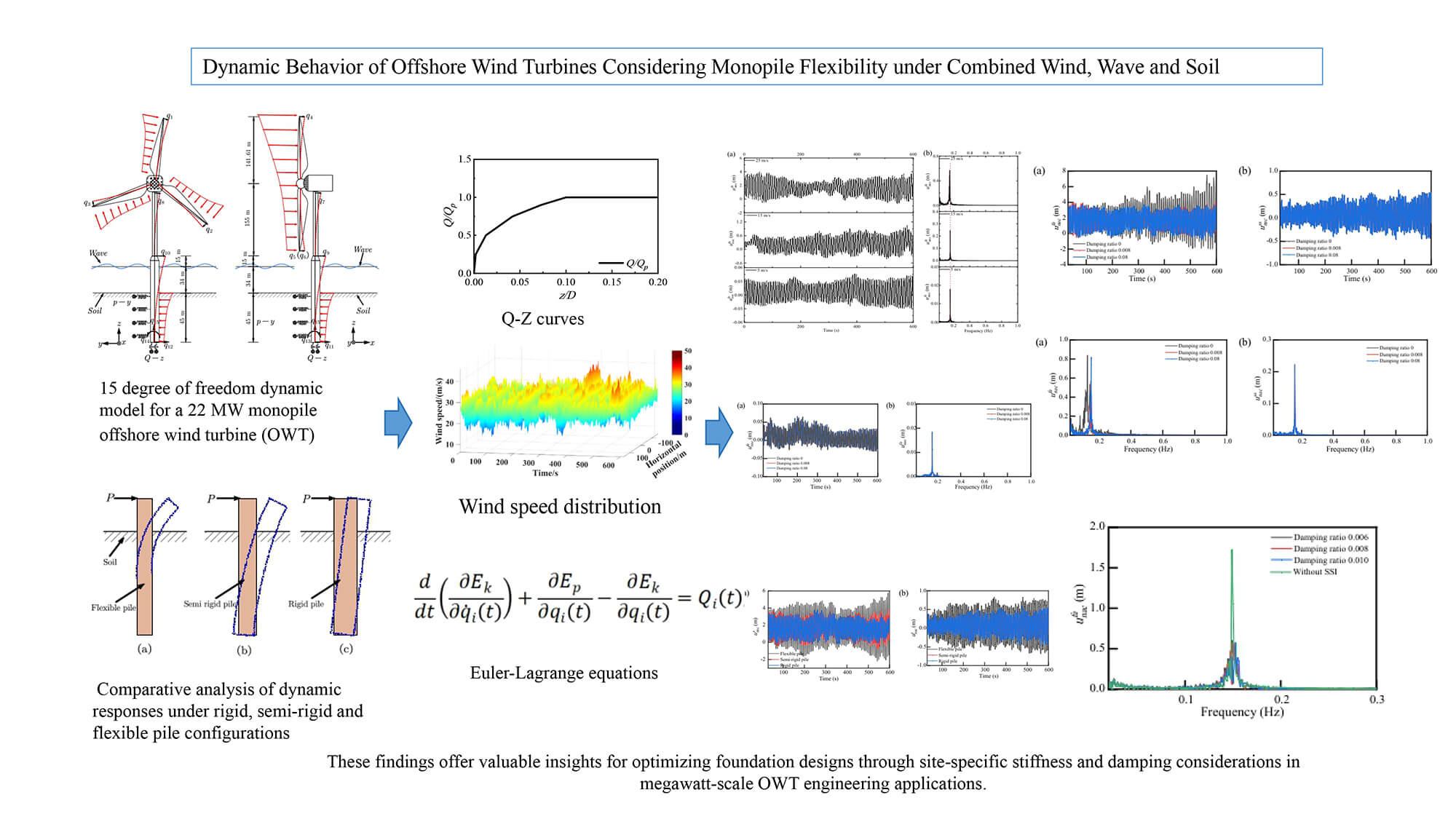
Offshore wind energy plays a critical role in achieving global decarbonization goals, while the dynamic response mechanisms of megawatt-scale turbines under complex environmental conditions remain insufficiently characterized. Current research often oversimplifies the effects of monopile flexibility and its interaction with soil dynamics, leading to gaps in dynamic predictions. To address this limitation, this study develops a comprehensive 15-degree-of-freedom dynamic model for a 22 MW monopile offshore wind turbine (OWT) that incorporates nonlinear pile flexibility and soil-structure interaction throughGraphic Abstract
Keywords
Global energy demand is increasing at an unprecedented rate due to rapid industrialization, technological advancements and population growth [1–3]. The rising demand, coupled with the environmental impacts of fossil fuels, drives a decisive transition toward renewable energy [4,5]. As a clean and sustainable energy source, wind power plays a pivotal role in decarbonizing global electricity systems [6]. In recent decades, substantial technological advancements have established onshore wind power as one of the most widely deployed sources globally [7,8]. However, the greatest potential for wind energy resides principally in offshore environments, where enhanced and steadier wind resources enable significantly higher energy yields [9]. This advantage at sea leads to increased capacity factors and the possibility of reduced levelized energy costs, strongly supporting offshore wind as the future of scalable renewable energy.
The rapid development of offshore wind energy has led to a growing interest in the design and analysis of megawatt-scale wind turbines [10]. As the industry progresses, turbines are becoming increasingly larger to capture higher energy yields, thereby improving overall efficiency. However, the megawatt-scale offshore wind turbines (OWTs) present significant challenges, particularly in understanding their dynamic characteristics. The ongoing upscaling of wind turbine dimensions significantly increases structural compliance, leading to amplified flexibility and larger deflections across blades, towers, and substructures. This increased sensitivity to environmental forces has a critical impact on the system’s overall performance [11]. Therefore, understanding these amplified flexible responses is essential for operational safety and efficiency. Moreover, the coupled dynamics of wind, waves and soil play a crucial role in turbine behavior, particularly in demanding offshore environments where multiple factors influence structural dynamics [12].
As offshore wind turbines increase in size and are deployed in increasingly complex environmental conditions, understanding their dynamic behavior has emerged as a crucial area of research. Numerous studies have investigated the aero-hydro-elastic-structural coupled behavior of OWTs under wind, wave, current, and seismic actions [13–15]. The development of sophisticated numerical frameworks, complemented by experimental validation, has significantly enhanced the understanding of system dynamics, particularly in the accurate prediction of vibrational characteristics [16–20]. However, existing numerical and experimental approaches exhibit notable limitations in fully capturing the dynamics of full-scale turbines. From a numerical perspective, current modeling techniques for OWT dynamics encompass a broad range but often involve a compromise between computational efficiency and physical fidelity. Low-order models enable rapid simulations but oversimplify soil-structure interaction and pile flexibility, resulting in inaccuracies in predicting system frequencies and damping ratios [21,22]. Conversely, high-fidelity finite element models (FEM) provide detailed representations of structural and soil behavior but demand substantial computational resources, thereby constraining their applicability in parametric design studies and load scenario analyses. Moreover, many FEM approaches inadequately model aerodynamic loading during rotor rotation, thus overlooking critical aeroelastic coupling effects under operational conditions. Experimentally, the high costs and technical constraints restrict tests to scaled model testing. Theoretical progress in analyzing the dynamic response of OWTs has been predominantly driven by the refinement of analytical formulations [23–25].
Although theoretical methods for analyzing OWT dynamics offer well-established benefits, including computational efficiency and simplified load modeling, they often fail to adequately account for the critical influence of soil-structure interaction (SSI) [26]. Even in cases where SSI is nominally incorporated, existing models typically represent monopiles as rigid components, an assumption that is increasingly challenged by the enhanced flexibility of large-diameter piles used to support contemporary megawatt-scale turbines [23]. This simplification neglects SSI effects, which significantly impact the system’s natural frequencies, damping characteristics, damping ratios and coupled dynamic responses under environmental loads, thereby undermining the accuracy of performance predictions for megawatt-scale OWT performance [27–29].
Current research on SSI in OWTs primarily relies on simplified soil models to approximate the seabed’s influence on monopile foundations. Therefore, the integration of both SSI effects and pile flexibility within dynamic analyses is crucial for the precise evaluation and design of OWTs. This study aims to explore the dynamic characteristics of megawatt-scale OWTs, emphasizing the importance of understanding the coupling effects between wind, wave and soil, and the resulting impact on the structural flexibility of the turbines. Considering the growing demand for renewable energy, this research is vital for advancing the design, optimization, and sustainability of offshore wind power.
2 Theories of OWT Considering Pile Foundation Flexibility
Fig. 1 illustrates a theoretical framework designed to simulate the multi-physical behavior of a monopile-supported OWT subjected to wind and wave loading, incorporating soil-boundary conditions. This study employs a 15-degree-of-freedom (DOF) multi-body dynamics framework to investigate the dynamic response of OWTs. Each blade is represented as a deformable body with two DOFs, capturing flapwise and edgewise bending deformations (

Figure 1: Schematic diagram of OWT model considering 15 DOFs
The absolute displacements of the nacelle and hub
where
The three velocity components of the nacelle and hub in three directions can be written as
According to these velocity components, the resultant absolute velocity of the nacelle
Using the same method, the tower’s absolute velocity
where
where
During OWT operation, the displacement and velocity of the blades exhibit continuous variation as a result of their rotational motion. This inherent dynamism requires the accurate formulation of rotational equations for each individual blade to effectively characterize and predict their kinematic behavior throughout the operational cycle. It is assumed that the rotating speed of the blade is
The absolute velocity components
where
When the platform experiences motion relative to the static equilibrium position, the kinetic energy of the system can be listed as follows
The first term in Eq. (8) denotes the kinetic energy of three blades, which is explained in detail in reference [24,30]. Parameter
The dynamic equations need to be determined based on the energy method, which requires separately calculating the kinetic energy and potential energy of the structure of OWT. By analyzing these energy components, the system’s equations of motion can be derived, ensuring an accurate representation of its dynamic behavior. The potential energy of this OWT system is determined as
where
The potential energy of the three blades includes elastic energy and the components induced by centrifugal and gravity forces.
In this equation, the centrifugal force
where
By substituting Eqs. (11) and (12) into Eq. (10), the potential energy of blades can be expressed as
where
The Lagrange equation is employed to derive the dynamic equation of the proposed model and is described as
where
where
By substituting Eqs. (8) and (9) into Eq. (16), the system’s dynamic equation can be established in a matrix form as
where
In this study, wind and wave directions are modeled as acting perpendicular to the rotor plane, a simplification grounded in the dynamic behaviors of OWT structures. The system’s primary dynamic response to wind loading occurs in both the fore-aft and side-to-side directions, whereas the response to wave loading is predominantly confined to the fore-aft direction. This is because under normal operating conditions, the active yaw control system continuously aligns the rotor plane with the prevailing wind and wave directions, ensuring that the dominant environmental forces act within this critical plane.
Some important assumptions are integral to this modeling framework. The analysis considers only unidirectional environmental loads, meaning that wind and waves are assumed to propagate from the same direction. Secondary directional components of these loads are neglected due to their negligible influence on the overall structural response, which simplifies the analysis without compromising its engineering accuracy. Additionally, wave forces are modeled using linear wave theory, which inherently assumes small wave amplitudes and idealized fluid behavior. Although this approach excludes nonlinear wave phenomena, it enhances computational efficiency while maintaining the model’s ability to capture the essential coupled dynamics of the wind-wave-structure-soil interaction system.
The wind speed is determined by the mean and turbulent components. In this study, the TurbSim program is used to obtain wind speed with time when the mean velocity at the hub height is 25 m/s. Fig. 2a shows the wind speed field of 22 MW OWT under different horizontal and vertical positions.

Figure 2: (a) Wind speed distribution over time at nacelle height and (b)
According to the principle of virtual work, the generalized force induced by wind can be obtained. The virtual work of aerodynamic load is described as
The generalized force induced by wind can be further determined as
Substituting Eq. (18) into Eq. (19), the expressions of the
Hydrodynamic loads play an equally critical role in analyzing the dynamic behavior of OWTs. Morison’s equation can be used to estimate the wave loading on the monopiles supporting. The horizontal force
where
A linear airy wave is adopted, and the wave surface elevation
where
The velocity and acceleration of fluid particles can be expressed as
where
The generalized force induced by the wave is determined by
Substituting Eq. (23) into Eq. (24), the expressions of the
In this model, the SSI effect is considered by the load forms, which can be described as the
where
Moreover,
where
The
In the dynamic analysis of wind turbine systems, soil damping plays a positive role in reducing dynamic loads on the structure. Consequently, it is imperative that the monopile dynamic model accurately incorporates soil damping to enhance the representation of complex dynamic interactions. It is important to note that current mainstream design standards (e.g., DNVGL and ISO) explicitly require consideration of soil damping in dynamic analysis. However, these standards do not provide explicit guidance regarding the determination of appropriate damping ratio values. Currently, most scholars empirically assume the damping ratio as a fixed value without consensus. Based on a comprehensive review of relevant studies, the damping ratio typically ranges between 0.17% and 8% [32–35]. Thus, 0, 0.008 and 0.08 are selected to further understand the influence of SSI. The inclusion of the zero-damping case (ζ = 0) serves as a theoretical baseline to isolate the specific contribution of soil damping to the overall system response. The value ζ = 0.008 corresponds to the recommended damping ratio for soft clays under operational loading conditions, while 8% damping represents an upper-bound value for high-energy dissipation scenarios in saturated cohesive soils. The virtual work associated with soil loading can be expressed as follows
The generalized force induced by the SSI effect can be determined by
Substituting Eq. (28) into Eq. (29), the expressions of the
3.1 Dynamic Response of OWTs under Different Wind Speeds
The IEA 22 MW OWT with a three-blade design is employed. Table 1 presents the important technical parameters of this OWT model, with additional details available in Reference [36]. The analysis of the monopile OWT incorporates operational load conditions characterized by a wind speed of 25 m/s, IEC Class A turbulence and linear wave conditions with a significant wave height of 4 m and a period of 12 s [37]. These parameters conform to industry standards for extreme operating scenarios, ensuring simulation representativeness for megawatt-scale OWT systems. To consider the dynamic SSI effect, the semi-rigid pile configuration with flexibility and displacement is explicitly modeled. The dynamic equation includes stiffness, mass and damping components with the 15 × 15 matrix. This high-dimensional formulation captures multi-directional interactions among the monopile, soil layers (via

Fig. 3a presents the amplitudes of nacelle displacement across wind speeds ranging from 5 to 25 m/s under a soil damping condition characterized by ζ = 0.008. The displacement profiles demonstrate a clear positive correlation with increasing wind velocity, as indicated by the progressively greater vertical separation observed at higher speeds. Specifically, the peak-to-peak displacement amplitudes exhibit a pronounced increase with rising wind speed, highlighting the significant influence of aerodynamic loading on the structural dynamic response. Fig. 3b displays the power spectral density (PSD) functions of nacelle displacement derived from Fourier transform analysis under different wind velocities of 5, 15 and 25 m/s, respectively. As wind velocity approaches the cut-out speed of 25 m/s, a significant shift in peak frequency occurs. The PSD results demonstrate a systematic evolution pattern in the nacelle displacement spectral density as wind speed increases from 5 to 25 m/s. The peak displacement amplitude shows a remarkable 31.7-fold increase, demonstrating the dominant role of aerodynamic loads in governing structural vibration energy. Particularly noteworthy is the 2.32-fold amplification observed within the wind speed range between 15 and 25 m/s, revealing the nonlinear growth characteristics of vibrational energy beyond rated operational conditions. The analysis further shows that the dominant frequency remains relatively stable within the 5–15 m/s range, whereas a 3.9% frequency shift is confined to the 15 to 25 m/s interval, indicating the progressively significant influence of high wind speeds on the structural frequency response.

Figure 3: The nacelle displacement in the fore-aft direction under different wind speed conditions with the soil damping scenarios of ζ = 0.008: (a) time-history and (b) spectrum
3.2 Dynamic Response of OWTs under Three Soil Damping Scenarios
Fig. 4a presents a comparative analysis of nacelle displacement responses in both the fore-aft and side-side directions under a cut-out wind speed of 25 m/s with three soil damping scenarios: undamped (ζ = 0), moderately damped (ζ = 0.008), and highly damped (ζ = 0.08). Throughout the initial 600-s simulation period, fore-aft displacements exhibited a reduction when soil damping is incorporated, with this attenuation becoming increasingly significant during the subsequent 300-s interval. This trend highlights the soil’s effectiveness in dissipating vibrational energy over time. Displacements in the y-direction exhibited minimal sensitivity to damping variations, suggesting that lateral soil resistance dominates damping effects in this direction. The results emphasize the critical role of soil damping in mitigating fore-aft direction vibrations for megawatt-scale monopile OWTs. The negligible side-side direction variation implies that aerodynamic and hydrodynamic loads predominantly govern transverse motions, whereas soil damping selectively attenuates fore-aft displacements. These results advocate for soil-specific damping calibration in foundation design to optimize structural reliability rather than over-engineering transverse stiffness.

Figure 4: The nacelle displacement responses under three soil damping scenarios of undamped (ζ = 0), moderately damped (ζ = 0.008) and highly damped (ζ = 0.08) in the (a) fore-aft and (b) side-side directions
Fig. 5 shows the PSD functions of nacelle displacements in the fore-aft and side-side directions. Under undamped SSI conditions, the frequency response spectra reveal distinct contributions from the tower’s natural frequency and wave load frequencies, accompanied by a notable shift in the tower’s dominant response frequency. When the soil damping ratio increases from 0 to 0.008, the peak displacement amplitude decreases by 32%, while the dominant frequency shifts upward by 16%. This phenomenon arises from the soil-induced modification of the system’s equivalent stiffness, which transforms a single dominant frequency into multiple closely spaced peaks with reduced amplitudes. Further increases in the soil damping ratio result in a rightward shift of these frequencies within the spectrum, consistent with the damping-dependent decrease in effective stiffness. Notably, when the damping ratio is elevated to 0.08, the displacement amplitude rebounds by 44%, whereas the frequency exhibits only a marginal additional increase of 1.7%, indicating a nonlinear threshold effect in the energy dissipation mechanisms of the soil-structure system. At higher damping levels, while amplitude attenuation continues, the frequency merging effect becomes prominent. Originally distributed spectral peaks coalesce into a single broadened peak, effectively narrowing the resonance bandwidth and reducing resonance susceptibility. Furthermore, higher damping ratios progressively suppress the visibility of wave-induced frequency components in the spectral domain. These results underscore the critical importance of explicitly incorporating both soil stiffness and damping effects in the dynamic response modeling of OWTs.

Figure 5: The PSD functions of nacelle displacements derived from Fourier transform analysis into the (a) fore-aft and (b) side-side directions
The results for the side-to-side direction in Fig. 5b indicate that the primary response frequency is largely unaffected by changes in soil damping ratios. Although an increase in damping leads to a reduction in amplitude, the extent of this attenuation is relatively minor. This lack of sensitivity to variations in damping is attributed to the comparatively lower load levels in this direction relative to other axes, which results in negligible differences in displacement amplitudes across all examined cases. The limited dynamic coupling observed in the side-to-side direction implies that the responses are mainly driven by aerodynamic and hydrodynamic forces rather than soil-structure interaction effects. Therefore, while soil damping plays a modest role in reducing amplitude, its impact on the frequency content and resonance behavior in the side-to-side direction is subordinate to the influence of external loading dynamics.
3.3 Dynamic Response of OWTs under Cutting in Wind Speed
Fig. 6 reveals near-identical displacement histories and PSD profiles in the fore-aft direction under cut-in wind speed conditions across different soil damping ratios. Both the time-domain responses and frequency spectra demonstrate consistency regardless of damping magnitude, indicating a negligible effect of soil damping mechanisms at this operational state. This consistency phenomenon primarily stems from the substantially reduced aerodynamic loads at cut-in wind speeds, where vibration energy levels remain below the activation threshold for effective soil damping participation. The observed PSD curves further confirms that damping-induced frequency shifts and amplitude attenuation, prominent under higher-load conditions, become negligible when excitation forces are insufficient to mobilize soil-structure interaction dynamics. These results show that optimizing foundation damping has limited effectiveness in reducing vibrations at cut-in wind speeds, highlighting the importance of tailoring OWT control strategies to specific load conditions.

Figure 6: The nacelle displacement in the fore-aft direction under cut-in wind speed conditions: (a) time-history and (b) spectrum
4.1 Determination of Pile Categories for 22 MW OWT
Based on deformation patterns and failure mechanisms, laterally loaded monopiles are categorized into flexible, semi-rigid and rigid piles [38], as illustrated in Fig. 7. Flexible piles, characterized by high slenderness ratios and greater embedment depths, primarily undergo deformation within the upper soil layers when subjected to horizontal loading. This response is attributed to the substantial lateral confinement exerted by the deeper soil strata, which effectively limits bending below a certain critical depth. In contrast, rigid piles with high bending stiffness exhibit negligible flexural deformation. Their behavior is characterized primarily by rigid-body translation and rotation at the pile base below the mudline. Passive soil resistance develops in the same direction as the applied lateral load, creating a counter-rotational moment. Semi-rigid piles display a combination of these behaviors, with flexural deformation occurring at shallow depths transitioning to rigid-body rotation at greater depths, thereby integrating displacement features of both flexible and rigid pile types. This classification framework provides critical insights for optimizing pile geometry and stiffness to match site-specific soil profiles and operational loading scenarios.

Figure 7: Deformation modes of horizontally loaded piles: (a) flexible pile, (b) semi-rigid pile and (c) rigid pile
The rigid-flexible classification of piles is defined by the dimensionless parameter
Utilizing geotechnical parameters aligned with IEC standards and the analytical framework of this study, the computed pile-soil relative stiffness ratio of
According to the dimensionless parameter
4.2 Stiffness-Dependent Dynamic Performance of OWT Monopiles
The proposed dynamic equations capture the fundamental differences in OWT behaviors between rigid and flexible piles through parametric degradation. When certain parameters
The displacement characteristics of the nacelle in both fore-aft and side-side directions under rigid, semi-rigid and flexible pile configurations are summarized in Fig. 8, based on the IEA 22 MW OWT. In the fore-aft direction, the flexible pile configuration yielded the largest displacement amplitudes, followed by semi-rigid and rigid piles, due to soil plasticity effects that partially offset the stiffness advantage of rigid piles. Notably, the semi-rigid pile exhibited a transitional behavior compared to the flexible and rigid configurations. In existing studies, many analytical models simplify pile foundations as rigid piles (i.e., assuming no deformation occurs under loading). However, this simplification leads to an underestimation of the predicted displacement response of the pile. In other words, the rigid pile assumption neglects the flexural deformation of the pile shaft and detailed SSI effects, resulting in calculated displacement values that are smaller than the actual values, thereby compromising the accuracy of the design. In contrast, the displacements in side-side direction show the same variations between semi-rigid and rigid piles under low transverse loading conditions, as the minimal loads failed to activate significant flexible effects. This characteristic highlights the critical role of load magnitude in governing SSI behavior.

Figure 8: The displacement characteristics of the nacelle in both (a) x- and (b) y-directions under rigid, semi-rigid, and flexible pile configurations
4.3 Engineering Applications, Limitations and Future Research
This study provides several valuable insights for the design and monitoring of megawatt-scale OWTs. Firstly, the identified frequency shifts and damping-sensitive responses associated with semi-rigid pile foundations indicate that foundation optimization should prioritize site-specific stiffness-damping matching rather than relying on generalized rigid-pile assumptions. The proposed 15-DOF model enables engineers to preliminarily assess resonance risks for particular soil conditions, thereby mitigating the necessity for overly conservative design approaches. Secondly, the clear directional dependence of SSI effects, with significant fore-aft damping but limited side-side influence, implies that structural health monitoring systems should focus on fore-aft accelerations to capture critical dynamic behaviors efficiently. Finally, the transitional behavior of semi-rigid piles highlights the importance of classifying pile flexibility using the dimensionless parameter
Some studies simplify the analysis by modeling the tower or pile base as a fixed support or by directly prescribing a stiffness matrix. This study compares the structural responses between two modeling approaches: one with a fixed pile base (neglecting wind, wave and soil coupling effects) and another that incorporates SSI interactions. The results demonstrate that ignoring soil effects leads to a significant overestimation of the amplitude response, as depicted in Fig. 9. In the dynamic equations, the soil damping ratio should be selected based on geotechnical site investigation. To provide a rational basis for this selection, a sensitivity analysis of the soil damping ratios is conducted in this study. Using a controlled variable approach, we systematically evaluated the impact of ±25% variations in the damping ratio (specifically, values of 0.006, 0.008, and 0.010) on the structural dynamic response, as illustrated in Fig. 9. The results indicate that changes in the damping ratio cause fluctuations in both the peak response and the system frequency. A 25% variation in the damping ratio causes approximately a 5% fluctuation in the peak response. Furthermore, the peak response frequency increases with higher damping ratios. Consequently, the selection of soil damping ratios in OWT foundation design should be grounded in comprehensive geotechnical investigations and account for their evolution under long-term cyclic loading conditions.

Figure 9: A sensitivity analysis of the soil damping ratios
However, the
In light of the findings and limitations identified in this study, several directions for future research are proposed. First, it is essential to develop more refined soil-structure interaction models, particularly three-dimensional models capable of capturing soil stiffness degradation under cyclic loading conditions. Second, field prototype testing targeting multi-megawatt OWTs should be conducted to acquire dynamic response data of the system in real environments, facilitating the validation and refinement of theoretical models. Third, research should focus on the dynamic response and control strategies under multi-hazard load couplings, such as combined wind-wave-current-earthquake excitations. Finally, the exploration of machine learning-based methods for rapid prediction of wind turbine dynamic responses will provide more efficient tools for engineering design and real-time monitoring. These research avenues will collectively enhance the dynamics analysis and design theory for multi-megawatt OWTs, thereby providing crucial support for the safe and reliable operation of renewable energy infrastructure.
This study systematically investigates the dynamic behavior of the megawatt-scale OWT under combined wind, wave and soil loads. For a 22 MW OWT, we analyze how monopile flexibility and SSI effects alter the system dynamics, leading to significant changes in natural frequencies and damping ratios. The dynamic behaviors of OWT with rigid pile, semi-rigid pile and flexible pile assumptions are further comparatively evaluated. The results highlight the necessity of site-specific SSI modeling to consider monopile stiffness and soil damping. This study provides engineers with a validated methodology for incorporating soil-structure interaction effects into OWT design processes. The proposed 15-DOF model serves as an efficient tool for preliminary foundation design and load calculation, bridging the gap between oversimplified models and computationally intensive simulations. The results directly support the optimization of monopile dimensions, fatigue load assessments and control system parameters for next-generation megawatt-scale OWTs, contributing to more economical and reliable offshore wind energy development.
Acknowledgement: Not applicable.
Funding Statement: This work was supported by the National Key Research and Development Program of China (Grants No. 2022YFB2402800).
Author Contributions: The authors confirm contribution to the paper as follows: Shengya Liu: methodology, writing—original draft. Wei Bian: methodology, supervision, investigation. Linan Li: funding acquisition, conceptualization, writing—reviewing and editing. Yang Xue: project administration, validation. Jingxun Yin: methodology, resources. All authors reviewed and approved the final version of the manuscript.
Availability of Data and Materials: Not applicable.
Ethics Approval: Not applicable.
Conflicts of Interest: The authors declare no conflicts of interest.
Abbreviations
| OWT | Offshore wind turbine |
| PSD | Power spectral density |
References
1. Maja MM, Ayano SF. The impact of population growth on natural resources and farmers’ capacity to adapt to climate change in low-income countries. Earth Syst Environ. 2021;5(2):271–83. doi:10.1007/s41748-021-00209-6. [Google Scholar] [CrossRef]
2. Hassan Q, Algburi S, Sameen AZ, Al-Musawi TJ, Al-Jiboory AK, Salman HM, et al. A comprehensive review of international renewable energy growth. Energy Built Environ. 2024;15:41. doi:10.1016/j.enbenv.2023.12.002. [Google Scholar] [CrossRef]
3. Dong Y, Tang G, Jia Y, Wang Z, Rong X, Cai C, et al. Review on research about wake effects of offshore wind turbines. Energy Eng. 2022;119(4):1341–60. doi:10.32604/ee.2022.019150. [Google Scholar] [CrossRef]
4. Zhang Y, Guo J, Peng H. Simulation of offshore wind turbine blade docking based on the Stewart platform. Energy Eng. 2023;120(11):2489–502. doi:10.32604/ee.2023.029496. [Google Scholar] [CrossRef]
5. Zhang J. Energy access challenge and the role of fossil fuels in meeting electricity demand: promoting renewable energy capacity for sustainable development. Geosci Front. 2024;15(5):101873. doi:10.1016/j.gsf.2024.101873. [Google Scholar] [CrossRef]
6. Veers P, Dykes K, Lantz E, Barth S, Bottasso CL, Carlson O, et al. Grand challenges in the science of wind energy. Science. 2019;366(6464):eaau2027. doi:10.1126/science.aau2027. [Google Scholar] [PubMed] [CrossRef]
7. Lei Z, Wang X, Zhou S, Wang Z, Wang T, Yang Y. A review of research status and scientific problems of floating offshore wind turbines. Energy Eng. 2022;119(1):123–43. doi:10.32604/ee.2022.016034. [Google Scholar] [CrossRef]
8. Xu L, Pang M, Zhang L, Poganietz WR, Marathe SD. Life cycle assessment of onshore wind power systems in China. Resour Conserv Recycl. 2018;132(1):361–8. doi:10.1016/j.resconrec.2017.06.014. [Google Scholar] [CrossRef]
9. Desalegn B, Gebeyehu D, Tamrat B, Tadiwose T, Lata A. Onshore versus offshore wind power trends and recent study practices in modeling of wind turbines’ life-cycle impact assessments. Clean Eng Technol. 2023;17:100691. doi:10.1016/j.clet.2023.100691. [Google Scholar] [CrossRef]
10. Fei W, Tan J, Li H, Zhu C, Sun Z, Wang H. Influences of planet gear journal bearing on dynamic characteristics of megawatt-scale wind turbine drivetrains: simulations and experiments. Mech Syst Signal Process. 2024;221(1):111747. doi:10.1016/j.ymssp.2024.111747. [Google Scholar] [CrossRef]
11. Sieros G, Chaviaropoulos P, Sørensen JD, Bulder BH, Jamieson P. Upscaling wind turbines: theoretical and practical aspects and their impact on the cost of energy. Wind Energy. 2012;15(1):3–17. doi:10.1002/we.527. [Google Scholar] [CrossRef]
12. Asgari A, Ahmadtabar Sorkhi SF. Wind turbine performance under multi-hazard loads: wave, wind, and earthquake effects on liquefiable soil. Results Eng. 2025;26:104647. doi:10.1016/j.rineng.2025.104647. [Google Scholar] [CrossRef]
13. Xie SY, Gao J, Li YR, Jiang SX, Zhang CL, He J. Aero-hydro-elastic-servo modeling and dynamic response analysis of a monopile offshore wind turbine under different operating scenarios. China Ocean Eng. 2024;38(3):379–93. doi:10.1007/s13344-024-0031-0. [Google Scholar] [CrossRef]
14. Lu Y, Xie W, Wang Y, Liang H, He Y, Chen X, et al. Dynamic analysis of MTMD vibration reduction for offshore wind turbine under combined wind-wave-seismic loads. Structures. 2025;72:108207. doi:10.1016/j.istruc.2025.108207. [Google Scholar] [CrossRef]
15. Liang J, Fu Y, Wang Y, Ou J. Identification of equivalent wind and wave loads for monopile-supported offshore wind turbines in operating condition. Renew Energy. 2024;237:121525. doi:10.1016/j.renene.2024.121525. [Google Scholar] [CrossRef]
16. Page AM, Skau KS, Jostad HP, Eiksund GR. A new foundation model for integrated analyses of monopile-based offshore wind turbines. Energy Proc. 2017;137:100–7. doi:10.1016/j.egypro.2017.10.337. [Google Scholar] [CrossRef]
17. Asareh MA, Schonberg W, Volz J. Effects of seismic and aerodynamic load interaction on structural dynamic response of multi-megawatt utility scale horizontal axis wind turbines. Renew Energy. 2016;86:49–58. doi:10.1016/j.renene.2015.07.098. [Google Scholar] [CrossRef]
18. Song M, Jiang Z, Liu K, Han Y, Liu R. Dynamic response analysis of a monopile-supported offshore wind turbine under the combined effect of sea ice impact and wind load. Ocean Eng. 2023;286(1):115587. doi:10.1016/j.oceaneng.2023.115587. [Google Scholar] [CrossRef]
19. Zhang D, Chen Z, Liu X, Sun J, Yu H, Zeng W, et al. A coupled numerical framework for hybrid floating offshore wind turbine and oscillating water column wave energy converters. Energy Convers Manag. 2022;267(1):115933. doi:10.1016/j.enconman.2022.115933. [Google Scholar] [CrossRef]
20. Zeng F, Zhang N, Huang G, Gu Q, He M. Experimental study on dynamic response of a floating offshore wind turbine under various freak wave profiles. Mar Struct. 2023;88:103362. doi:10.1016/j.marstruc.2022.103362. [Google Scholar] [CrossRef]
21. Lin Z, Cevasco D, Collu M. A methodology to develop reduced-order models to support the operation and maintenance of offshore wind turbines. Appl Energy. 2020;259:114228. doi:10.1016/j.apenergy.2019.114228. [Google Scholar] [CrossRef]
22. Ferri G, Marino E. Site-specific optimizations of a 10 MW floating offshore wind turbine for the Mediterranean Sea. Renew Energy. 2023;202:921–41. doi:10.1016/j.renene.2022.11.116. [Google Scholar] [CrossRef]
23. Jahangiri V, Sun C. Three-dimensional vibration control of offshore floating wind turbines using multiple tuned mass dampers. Ocean Eng. 2020;206:107196. doi:10.1016/j.oceaneng.2020.107196. [Google Scholar] [CrossRef]
24. Sun C. Mitigation of offshore wind turbine responses under wind and wave loading: considering soil effects and damage: mitigation of offshore wind turbine responses under wind and wave loading: considering soil effects and damage. Struct Control Health Monit. 2018;25(3):e2117. doi:10.1002/stc.2117. [Google Scholar] [CrossRef]
25. Yang Y, Bashir M, Li C, Michailides C, Wang J. Mitigation of coupled wind-wave-earthquake responses of a 10 MW fixed-bottom offshore wind turbine. Renew Energy. 2020;157:1171–84. doi:10.1016/j.renene.2020.05.077. [Google Scholar] [CrossRef]
26. Song Y, Lu D, Zuo J, Wang W, Li X. Dynamic characteristics of monopile offshore wind turbine with different equivalent pile foundation boundaries under winds, waves and earthquakes. Appl Ocean Res. 2025;154:104391. doi:10.1016/j.apor.2024.104391. [Google Scholar] [CrossRef]
27. Shi S, Zhai E, Xu C, Iqbal K, Sun Y, Wang S. Influence of pile-soil interaction on dynamic properties and response of offshore wind turbine with monopile foundation in sand site. Appl Ocean Res. 2022;126:103279. doi:10.1016/j.apor.2022.103279. [Google Scholar] [CrossRef]
28. Wang T, Yu S, Wu X, Tang C. Lateral dynamic response of monopile offshore wind turbines in radially softened layered soil. Ocean Eng. 2024;299:117289. doi:10.1016/j.oceaneng.2024.117289. [Google Scholar] [CrossRef]
29. Prowell I, Elgamal A, Lu J. Modeling the influence of soil structure interaction on the seismic response of a 5 MW wind turbine. In: Proceedings of the 5th International Conference on Recent Advances in Geotechnical Earthquake Engineering and Soil Dynamics; 2010 May 24–29; San Diego, CA, USA. p. 1–8. [Google Scholar]
30. Sun C. Semi-active control of monopile offshore wind turbines under multi-hazards. Mech Syst Signal Process. 2018;99:285–305. doi:10.1016/j.ymssp.2017.06.016. [Google Scholar] [CrossRef]
31. Zwerneman F, Digre D. Insights into using the 22nd edition of API RP 2A recommended practice for planning, designing and constructing fixed offshore platforms-working stress design. In: Proceedings of the Offshore Technology Conference; 2010 May 3–6; Houston, TX, USA. doi:10.2523/20837-ms. [Google Scholar] [CrossRef]
32. Carswell W, Johansson J, Løvholt F, Arwade SR, Madshus C, DeGroot DJ, et al. Foundation damping and the dynamics of offshore wind turbine monopiles. Renew Energy. 2015;80:724–36. doi:10.1016/j.renene.2015.02.058. [Google Scholar] [CrossRef]
33. Damgaard M, Andersen JKF, Ibsen LB, Andersen LV. Natural frequency and damping estimation of an offshore wind turbine structure. In: Proceedings of the Twenty-second (2012) International Offshore and Polar Engi-neering Conference; 2012 Jun 17–22; Rhodes, Greece. p. 300–7. [Google Scholar]
34. Bisoi S, Haldar S. Design of monopile supported offshore wind turbine in clay considering dynamic soil-structure-interaction. Soil Dyn Earthq Eng. 2015;73:103–17. doi:10.1016/j.soildyn.2015.02.017. [Google Scholar] [CrossRef]
35. Bisoi S, Haldar S. 3D modeling of long-term dynamic behavior of monopile-supported offshore wind turbine in clay. Int J Geomech. 2019;19(7):04019062. doi:10.1061/(asce)gm.1943-5622.0001437. [Google Scholar] [CrossRef]
36. Collier W, Ors D, Barlas T, Zahle F, Bortolotti P, Marten D, et al. Aeroelastic code comparison using the IEA 22MW reference turbine. J Phys Conf Ser. 2024;2767(5):052042. doi:10.1088/1742-6596/2767/5/052042. [Google Scholar] [CrossRef]
37. James JP, Panchang V. Assessment of joint distributions of wave heights and periods. Ocean Eng. 2024;313:119501. doi:10.1016/j.oceaneng.2024.119501. [Google Scholar] [CrossRef]
38. Hong Y, He B, Wang LZ, Wang Z, Ng CWW, Mašín D. Cyclic lateral response and failure mechanisms of semi-rigid pile in soft clay: centrifuge tests and numerical modelling. Can Geotech J. 2017;54(6):806–24. doi:10.1139/cgj-2016-0356. [Google Scholar] [CrossRef]
39. Poulos HG, Hull TS. The role of analytical geomechanics in foundation engineering. In: Foundation engineering: current principles and practices. Reston, VA, USA: Amer Society of Civil Engineers; 1989. p. 1578–606. [Google Scholar]
Cite This Article
 Copyright © 2026 The Author(s). Published by Tech Science Press.
This work is licensed under a Creative Commons Attribution 4.0 International License , which permits unrestricted use, distribution, and reproduction in any medium, provided the original work is properly cited.
 Downloads
 Citation Tools
