
 Submit a Paper
 Propose a Special lssue
 Open Access
ARTICLE

On the Effect of Mist Flow on the Heat Transfer Performances of a Three-CopperSphere Configuration
Department of Electromechanical Engineering, University of Technology-Iraq, Baghdad, Iraq
* Corresponding Author: Karema A. Hamad. Email:
(This article belongs to the Special Issue: Recent advancements in thermal fluid flow applications)
Fluid Dynamics & Materials Processing 2023, 19(11), 2863-2875. https://doi.org/10.32604/fdmp.2023.029049
Received 23 January 2023; Accepted 18 April 2023; Issue published 18 September 2023
 View Full Text
 Download PDF
Abstract
The cooling of a (pebble bed) spent fuel in a high-temperature gas-cooled reactor (HTGR) is adversely affected by an increase in the temperature of the used gas (air). To investigate this problem, a configuration consisting of three copper spheres arranged in tandem subjected to a forced mist flow inside a cylindrical channel is considered. The heat transfer coefficients and related variations as a function of Reynolds number are investigated accordingly. The experimental results show that when compared to those with only airflow, the heat transfer coefficient of the spherical elements with mist flow (j = 112 kg/m2 hr, Re = 55000) increases by 180%, 75%, and 20%, respectively for the first, second, and third spherical element (the corresponding heat transfer enhancement ratio being 2.3, 1.4, and 1.1). Additional numerical simulations reveal that the presence of stagnant zones with intense vortex formation around each spherical element contributes significantly to determine the heat transfer behavior.Keywords
The advancement of thermal power facilities is directly related to the resolution of problems such as increasing reliability and operational properties, efficiency, lowering material consumption, and cost intensity [1]. During the maintenance and reloading of a high-temperature gas-cooled reactor (HTGR), high-temperature pebble bed spent fuel is produced and stored in dry, air-cooled casks before being reprocessed or refabricated. Improved heat transfer in such spent fuel can increase reliability and integrity while also shortening the cooling time of the fuel, lowering the cost intensity [2–5]. The use of two-phase mist flow is a highly effective heat transfer method that can provide heat transfer coefficients that are even higher than those found in other methods. According to [6–8], the deposition and subsequent evaporation of water droplets on a heated surface determines heat transfer enhancement. Most studies assumed that the carrier gas and dispersed water droplet velocities were the same, and that droplet aerodynamic drag forces obeyed the Stokes law. The inertia of water droplets in this case is directly related to the geometry of the flow area around the heated surface as well as the two-phase flow parameters. As a result of the deposition of water droplets on successively heated surfaces, the concentration of dispersed water droplets in the flow area changes significantly compared to its initial rate [9]. In this regard, Novak et al. [10] used three different nozzle designs to investigate a nozzle-generated air/water mist for vertical channel cooling. According to their findings, nozzle designs and mean droplet diameter have a significant impact on cooling performance. They also claimed that the air assisted nozzle design improved heat transfer due to the extremely high turbulence intensity caused by the high velocity jet. The effect of ultrasonic-generated water mist on the cooling performance of a vertical channel with upward and downward flow patterns under forced convection was investigated by Abed et al. [11]. In comparison to only air cooling, their experimental results revealed that for a range of mist concentration and carrier air velocity, the average Nusselt number improved by up to 224%. Furthermore, the reported uniform distribution of water mist for the upward flow case was due to the early and rapid deposition of water droplets in the entrance region of the cooled cylinder. Baragh et al. [12] investigated heat transfer by mist flow in a channel with various arrangements of porous media inserted at the channel core under laminar and forced convection. It was discovered that combining mist flow with a porous medium has a significant impact on heat transfer enhancement. High levels of heat transfer enhancement were between 100% and 265% for the transient flow regime, while at a high Reynolds number under constant heat flux, the enhancement was around 467.7%. Abed et al. [13] investigated the effect of using ultrasonic-generated mist flow on the cooling performance of a staggered tube bundle heat exchanger experimentally. The results showed that using micro-sized water mist can increase the rate of heat transfer by up to 270% when compared to single-phase air cooling for all heat exchanger rows over a wide mist rate range. Pakhomov et al. [14] used an Eulerian model to investigate the heat transfer enhancement by mist flow of a pipe with sudden expansion. They discovered that adding evaporating droplets increased heat transfer rate by 1.5 times when compared to single-phase flow with low mist concentration (0.05). The addition of small, non-evaporating droplets results in a slight increase in heat transfer rate. Wang et al. [15] numerically investigated the effects of mist flow on the hot section cooling performance of a gas turbine with different hole geometries. According to the findings, using a mist concentration of 10%–20% improved cooling performance by 5%–10%. Furthermore, they discovered that water droplets with diameters ranging from 5 to 20 mm tend to move away from the wall, reducing cooling performance. Abed et al. [16] have also investigated other specific factors on cooling heated surfaces using mist flow. They investigated the cooling performance of a heated spherical element inside a cylindrical channel using steady and unsteady heat transfer conditions. As a result of the comparison of steady and unsteady heat transfer, three heat transfer regimes were identified: The dry zone corresponds to the convection regime, while the dry-out and wet zones correspond to the evaporation and convection regimes, respectively. The current study aims to broaden the research field of mist flow cooling systems by highlighting the effects of several parameters such as gas velocity, water mist rate, and heat flux on the cooling performance of three copper spheres arranged in tandem using an ultrasonic mist generator under forced convection heat transfer conditions. As a result, the research gap in this study is the lack of previous research on the changes in mist rate in the flow direction caused by mist deposition on successively heated surfaces and their effects on cooling performance. This study will present a novel understanding and development of cooling methods for fuel elements used in a gas-cooled reactor using mist flow.
To investigate and analyse the effects of air and mist flows on the heat transfer performance of three copper spheres arranged in tandem configuration, a fully experimental system was designed and built. Fig. 1 shows a real photo of the experimental system, which included a cylindrical channel, mixing unit, air blower, copper spheres, and measurement tools. The channel was vertically mounted and made of an adiabatic material with a 0.0025 m wall thickness, 0.05 m diameter, and 0.94 m total length. To simulate the fuel elements in a gas-cooled reactor, three 0.34 m diameter copper spheres with internal electric heaters were placed inside the channel with a 2 dsp distance between them. The electric heaters are 0.008 m in diameter and 0.031 m in length, respectively, and are equipped with an AC voltage regulator to regulate and achieve the required heat flux. The mist flow was created in the mixing unit by combining blower air and water droplets from the ultrasonic generator operating at 1.7 MHz. During the experiments, the electrical power supplied to the heaters inside the spheres, their surface temperature with two K-type thermocouples, and the temperature of the mist flow in the mixing unit were all measured. To record the measured temperature, all used thermocouples connected to a digital thermometer type () and then to a computer. A pitot tube with a digital manometer was used to measure the velocity of the supplied air.
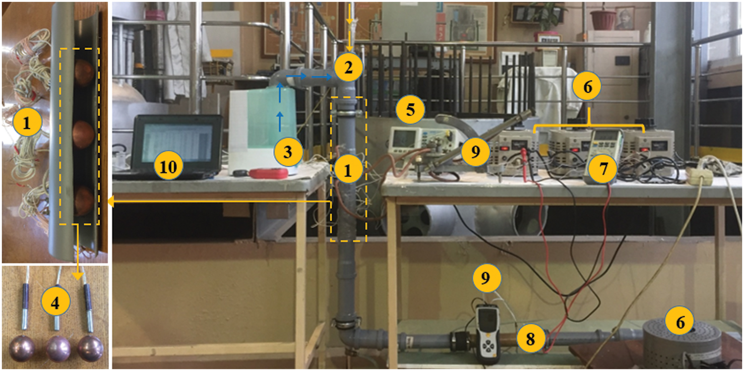
Figure 1: Shows the experimental system configuration. 1. Adiabatic channel, 2. Mixing unit, 3. Ultrasonic mist generator, 4. Spherical elements with electric heaters, 5. Thermometer digital, 6. AC voltage regulator, 7. Multimeter; 8. Pitot tube, 9. Manometer, and 10. Computer
3 Uncertainty Analysis and Data Processing
The heat transfer coefficient values were calculated by dividing the net power supplied to spherical elements by the difference between the average surface temperature of the sphere Tav.sph and the oncoming flow Tin multiplied by the sphere area under steady-state conditions and constant heat flux on the surface of the sphere elements, taking into account the heat loss Qlos in the sphere supported bar.
The following formula is used to compute the corresponding Nusselt number (Nu):
The Reynolds number (Re) is calculated as follows:
Because the ultrasonic transducer at 1.7 MHz produces a water mist with an ultra-fine diameter, Lang [17] proposed the following formula based on the capillary wave mechanism to determine the diameter of the water droplets generated by the ultrasonic generator:
The Stokes number (Stk) is calculated as follows [18]:
The irrigation density of mist flow is calculated as follows:
where G is the mass flow rate of water mist in kg/hr. To improve the reliability of the obtained data as well as the experimental setup, the uncertainties in the heat transfer coefficient, Nusselt number, and friction factor were eliminated using the Eqs. (7)–(9) presented by [19].
where
Both air and mist flows were carried out under the same hydrodynamic conditions with the Reynolds number from 2500 to 55000 and the heat flux q = 10200 W/m2 in order to analyse the heat transfer characteristics of spherical elements placed in the restricted conditions of a cylindrical channel. The obtained results allow us to evaluate the critical factors that influence heat transfer in both cases. Before conducting the mist flow experiments, the first spherical element was tested with only air to confirm and validate the experimental setup. Fig. 2 depicts the Abed et al. [16], Whitaker [20], and Romkes et al. [21] correlations for the heat transfer rate in terms of Nusselt number (Nu). The comparison shows that the current results and the empirical correlations are very close. This demonstrates the dependability of the experimental setup and process employed in the current study. Fig. 3 depicts the heat transfer coefficient data obtained for three spherical elements with different Re numbers sequentially placed inside the channel. As expected, an increase in the heat transfer coefficient was observed for a single-phase air flow, both with an increase in the Reynold numbers and for each sphere element in the wake after the first one, followed by stabilisation of the heat transfer coefficient beginning with the third sphere.
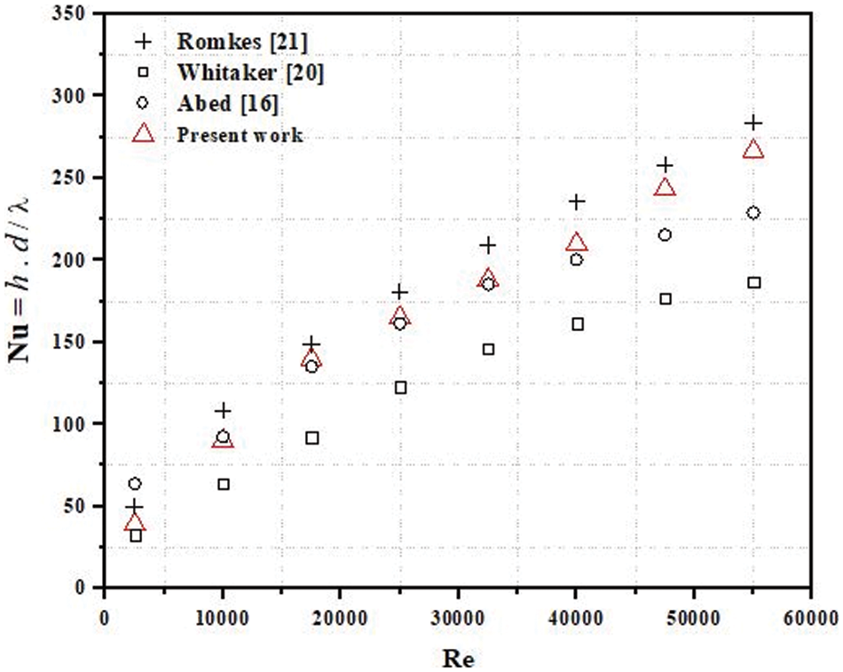
Figure 2: Nussult number (Nu) vs. Reynolds number (Re) at j = 0 kg/m2 hr
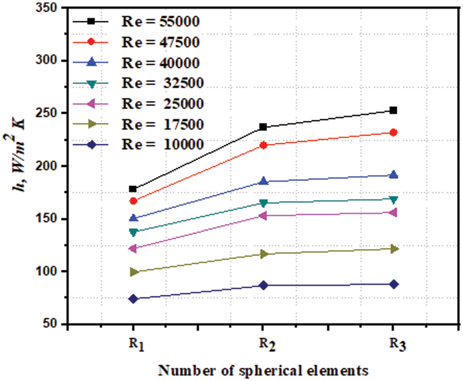
Figure 3: Heat transfer coefficient comparison of three spherical elements with j = 0 kg/m2 hr
The following empirical colorations are developed from the obtained data for the first, second, and third spheres for D/dsph = 1.35:
When mist flow was used, the distribution of heat transfer coefficients was observed to follow the opposite pattern (see Figs. 4 and 5). The first spherical element, on whose surface a significant portion of the mist flow’s water droplets settled, had the highest heat transfer coefficient values. This was confirmed by further investigation of the droplet settling mechanism developed in this study. When comparing the heat transfer enhancement of spherical elements in air and mist flows at the same Reynolds numbers, the influence of heat and mass transfer on the heat transfer coefficient is especially evident. Figs. 6–8 show a significant decrease in heat and mass transfer for the second and third spherical elements at irrigation densities ranging from 46 to 112 kg/m2 hr. The general trend of the heat transfer process is a reduction in heat transfer coefficients from the first to the last element, and for the third element—to the level of heat transfer with only air flow. All of this suggests that the concentration of water droplets deposited on the surface of the spherical elements as they flow around in the channel has decreased significantly.

Figure 4: Heat transfer coefficient comparison of three spherical elements with j = 88 kg/m2 hr

Figure 5: Heat transfer coefficient comparison of three spherical elements with j = 112 kg/m2 hr

Figure 6: Heat transfer enhancement ratio comparison of three spherical elements with j = 46 kg/m2 hr

Figure 7: Heat transfer enhancement ratio comparison of three spherical elements with j = 88 kg/m2 hr
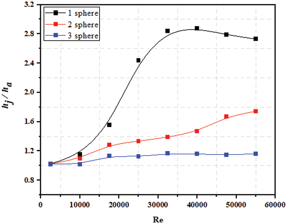
Figure 8: Heat transfer enhancement ratio comparison of three spherical elements with j = 112 kg/m2 hr
5 Modeling and Analysis of Heat Transfer Characteristics
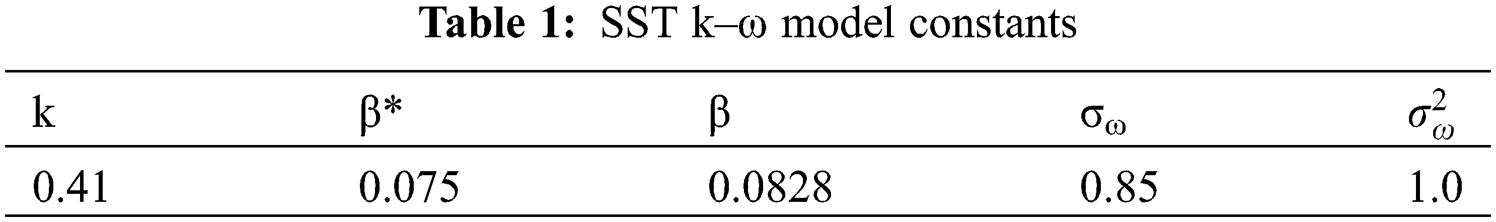
Different hydrodynamic conditions of the flow around their surface can be expected when using single-phase or mist flows on three copper spheres arranged in tandem configuration in a cylindrical channel, resulting in a significant difference in their heat transfer characteristics. If the first spherical element is in the zone with the least amount of turbulence, the subsequent ones are in the zone of the vortex wake from each of their predecessors. In this case, simulation of the flow around the spherical elements in the cylindrical channel under constrained conditions can be useful in estimating and predicting the general flow pattern. As a result, the flow was simulated in three dimensions using ANSYS FLUENT v.17 and the three-dimensional Reynolds-averaged Navier-Stokes equation solved by using simple algorithm. To solve the system of equations, the turbulence model SST k-ω was used (see Eqs. (14)–(16)), which combines the advantages of the k-ε and k-ω models and determines the turbulent effect near the surface with the highest accuracy of shear stress and heat transfer on the sphere surface. Table 1 shows the constants of SST k-ω model. For the convective components in the momentum, energy, and turbulence equations, a second-order upwind scheme is employed [22].
The conservation of mass (continuity equation):
- Momentum equation:
- Energy conservation equation
- Kinematic Eddy Viscosity
- Turbulence Kinetic Energy
- Specific Dissipation Rate
Fig. 9 depicts the computational domain, which includes the channel’s inlet, sphere, and outlet sections. The generated grid’s dependence is studied using four different computational grids with total elements (for fluid and solid regions) ranging from 1.35 to 2.05 million. Table 2 indicates that the grid with 2.05 million element numbers is good enough for the test. The inlet flow velocity ranged from 0.89 to 18.9 m/s, the air temperature at the inlet section was 298 K, and the heat flux on the sphere surface was equal to 10 kW/m2. Under normal conditions, i.e., at +25°C and atmospheric pressure, it was assumed that the flow is incompressible with an initial level of turbulence of 1%. Fig. 10 depicts the numerical simulation results as streamlines velocity with successive air flow around sphere elements for Re = 2.5 · 103 and Re = 5.5 · 104 values. The values of the temperature distribution on the surface of the spherical elements are also given in Fig. 11, indicating the corresponding non-uniformity of local heat transfer. The presence of the channel’s restrictive walls and spherical elements causes the formation of stable vortex zones that occupy a large portion of the channel cross section. In a narrow region between the channel walls and the spherical surface, the flow velocity sharply increases and subsequently remains noticeably higher along the channel walls, resulting in the formation of a near-wall annular layer that interacts with stagnant vortex zones in the space between the spheres. When water droplets are present in the flow, they move at the velocity of the carrier air flow, and the overall pattern of the flow around the elements by the carrier flow is obviously maintained, but accompanied by droplets deposition on the sphere surfaces.

Figure 9: (a) Computational domain, (b) Mesh models
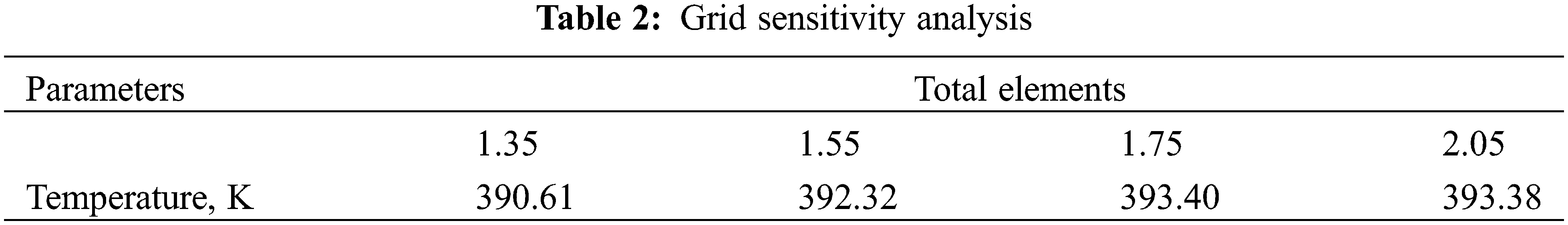

Figure 10: Velocity of streamlines around spherical elements

Figure 11: Depicts the temperature distribution across the surface of spherical elements
The effective number of droplets deposited on the surface of the sphere elements is defined as the number of droplets deposited on the surface divided by the total number of droplets in the flow. The effective parameter for a single cylinder is defined as [23]:
where the Stokes number (Stk) determines the likelihood of water droplets settling on the surface of spheres with diameter ddrop at a velocity u equal to the flow velocity u. In the range of Reynolds numbers, the effective parameter for water droplets with a diameter of (ddrop = 2.7 µm) is between = 0.26 ... 0.45. Re = 2.5 ∙ 103 … 5.5 ∙ 104.
The analogue parameter (η) represents the relative amount of water droplets (n) deposited on the surface of the spheres in accordance with the heat balance equation for cooling its surface, taking into account droplets reheating on the surface:
The theoretical values of parameter (n) for each of the spheres, on the upper half of which water droplets settle, are determined using experimental values of heat transfer coefficients for air and mist flows (ha and hj).
Fig. 12 depicts the relative amount of water droplets deposited on the surface of spherical elements as a function of the Reynolds number at j = 112, 88, and 46 kg/m2 hr irrigation densities. According to the data analysis, the values of parameter (n) are determined by the position of the spherical elements in the channel and do not depend on the irrigation density.

Figure 12: Depicts the relative amount of water droplets deposited on the surface of 1, 2, and 3 spherical elements depending on the Re number under irrigation density j = 112; 88 and 46 kg/m2 hr for each element; 4-effective deposition parameter [24]
A significant non-uniformity in the direction of flow characterises the heat transfer enhancement of three copper spheres arranged in tandem configuration in a cylindrical channel cooled by a mist flow. The first element has a heat transfer coefficient that is 2.3 times greater than the second and third elements. The constrained flow conditions in the channel around the spheres contribute to the formation of stagnant zones with high levels of vortex formation and the near-wall annular region of the flow with droplet, which determines the disparity of its deposition on the surface and a decrease in the heat and mass transfer of the second and third ball elements. The droplet deposition on the first element determines the subsequent flow behaviour and heat transfer features between the spheres surface and the mist flow.
Funding Statement: The authors received no specific funding for this study.
Conflicts of Interest: The authors declare that they have no conflicts of interest to report regarding the present study.
References
1. Wang, J., Li, Q., Sundén, B., Baleta, J., Vujanović, M. (2017). Two-phase flow simulation of mist film cooling with deposition for various boundary conditions. Numerical Heat Transfer, Part A: Applications, 71(9), 895–909. [Google Scholar]
2. Wang, S. K., Liu, Y. H. (2019). Heat transfer and friction measurement in pin-fin arrays under mist flow condition. Journal of Thermal Science and Engineering Applications, 11(2), 021012. [Google Scholar]
3. Abdelmaksoud, R., Wang, T. (2020). Simulation of air/mist cooling in a conjugate, 3-D gas turbine vane with internal passage and external film cooling. International Journal of Heat and Mass Transfer, 160, 120197. [Google Scholar]
4. Tuo, H., Hrnjak, P. (2014). Enhancement of vapor-liquid separation in vertical impact T-junctions for vapor compression systems with flash gas bypass. International Journal of Refrigeration, 40, 43–50. [Google Scholar]
5. Wang, Q., Su, X., Feng, Y., Wang, H., Song, J. (2021). Experimental study of gas-water two-phase flow patterns in fracture: Implication for enhancing coalbed methane production. Journal of Petroleum Science and Engineering, 207, 109168. [Google Scholar]
6. Ragab, R., Wang, T. (2018). An experimental study of Mist/Air film cooling with fan-shaped holes on an extended flat plate—Part II: Two-phase flow measurements and droplet dynamics. Journal of Heat Transfer, 140(4), 042202. [Google Scholar]
7. Ho, P. T., Liu, Y. H. (2019). Heat transfer and pressure drop of air/water mist flow in horizontal Minichannels. Heat and Mass Transfer, 55, 1347–1358. [Google Scholar]
8. Abed, A. H., Shcheklein, S. E., Pakhaluev, V. M. (2019). Investigation of heat transfer coefficient of spherical element using infrared thermography (IR) and gas-water droplets (mist) as working medium. IOP Conference Series: Materials Science and Engineering, vol. 481, no. 1, 012033. Russian Federation, IOP Publishing. [Google Scholar]
9. Huang, K. T., Liu, Y. H. (2019). Enhancement of mist flow cooling by using V-shaped broken ribs. Energies, 12(19), 3785. [Google Scholar]
10. Novak, V., Sadowski, D. L., Schoonover, K. G., Abdel-Khalik, S. I., Ghiaasiaan, S. M. (2008). Heat transfer in two-component internal mist cooling: Part I. Experimental investigation. Nuclear Engineering and Design, 238(9), 2341–2350. [Google Scholar]
11. Abed, A. H., Khlief, A. K., Jabal, M. H. (2021). Experimental investigation on mist flow and heat transfer in a uniformly heated vertical cylinder. International Journal of Heat and Technology, 39(6), 1835–1844. [Google Scholar]
12. Baragh, S., Shokouhmand, H., Ajarostaghi, S. S. M. (2019). Experiments on mist flow and heat transfer in a tube fitted with porous media. International Journal of Thermal Sciences, 137, 388–398. [Google Scholar]
13. Abed, A. H., Shcheklein, S. E., Pakhaluev, V. M. (2020). Experimental investigation in improving thermal performance of passive heat removal system using mist assisted evaporative cooling. Journal of Advanced Research in Fluid Mechanics and Thermal Sciences, 69(1), 98–109. [Google Scholar]
14. Pakhomov, M. A., Terekhov, V. I. (2017). The effect of droplets evaporation on turbulence modification and heat transfer enhancement in a two-phase mist flow downstream of a pipe sudden expansion. Flow, Turbulence and Combustion, 98, 341–354. [Google Scholar]
15. Wang, T., Li, X. (2008). Mist film cooling simulation at gas turbine operating conditions. International Journal of Heat and Mass Transfer, 51(21–22), 5305–5317. [Google Scholar]
16. Abed, A., Shcheklein, S., Pakhaluev, V. (2021). Comparative study on steady and unsteady heat transfer analysis of a spherical element using air/water mist two-phase flow. Thermal Science, 25(1), 625–635. [Google Scholar]
17. Lang, R. J. (1962). Ultrasonic atomization of liquids. The Journal of the Acoustical Society of America, 34(1), 6–8. [Google Scholar]
18. Hinds, W. C., Zhu, Y. (2022). Aerosol technology: Properties, behavior, and measurement of airborne particles. Hoboken, New Jersey, USA: John Wiley & Sons. [Google Scholar]
19. Line, A. G. (1986). Guide engineering analysis of experimental data. https://www.ashrae.org/ [Google Scholar]
20. Whitaker, S. (1972). Forced convection heat transfer correlations for flow in pipes, past flat plates, single cylinders, single spheres, and for flow in packed beds and tube bundles. AIChE Journal, 18(2), 361–371. [Google Scholar]
21. Romkes, S. J. P., Dautzenberg, F. M., van den Bleek, C. M., Calis, H. P. A. (2003). CFD modelling and experimental validation of particle-to-fluid mass and heat transfer in a packed bed at very low channel to particle diameter ratio. Chemical Engineering Journal, 96(1–3), 3–13. [Google Scholar]
22. Hu, Y., Yang, J., Wang, J., Wang, Q. (2018). Investigation of hydrodynamic and heat transfer performances in grille-sphere composite pebble beds with DEM-CFD-Taguchi method. Energy, 155, 909–920. [Google Scholar]
23. Hodgson, J. W., Saterbak, R. T., Sunderland, J. E. (1968). An experimental investigation of heat transfer from a spray cooled isothermal cylinder. Journal of Heat Transfer, 90(4), 457–463. https://doi.org/10.1115/1.3597542 [Google Scholar] [CrossRef]
24. Hayashi, Y., Takimoto, A., Matsuda, O. (1991). Heat transfer from tubes in mist flows. Experimental Heat Transfer an International Journal, 4(4), 291–308. [Google Scholar]
Cite This Article
 Copyright © 2023 The Author(s). Published by Tech Science Press.
This work is licensed under a Creative Commons Attribution 4.0 International License , which permits unrestricted use, distribution, and reproduction in any medium, provided the original work is properly cited.
 Downloads
 Citation Tools