
 Submit a Paper
 Propose a Special lssue
 Open Access
ARTICLE

Design and Experimental Testing of an Electric Field-Driven Droplet Injection Device
1
College of Mechatronics, Xuchang University, Xuchang, 461000, China
2
State Key Laboratory of High Performance Complex Manufacturing, Central South University, Changsha, 410083, China
3
State Key Laboratory of Mechanical Transmission, Chongqing University, Chongqing, 400044, China
4
Tobacco Sheet Manufacturing Department, Henan Cigarette Industry Tobacco Sheet Limited Company, Xuchang, 461100, China
* Corresponding Authors: Fulai Cao. Email: ; Yanpu Chao. Email:
Fluid Dynamics & Materials Processing 2023, 19(11), 2891-2905. https://doi.org/10.32604/fdmp.2023.029243
Received 09 February 2023; Accepted 03 April 2023; Issue published 18 September 2023
 View Full Text
 Download PDF
Abstract
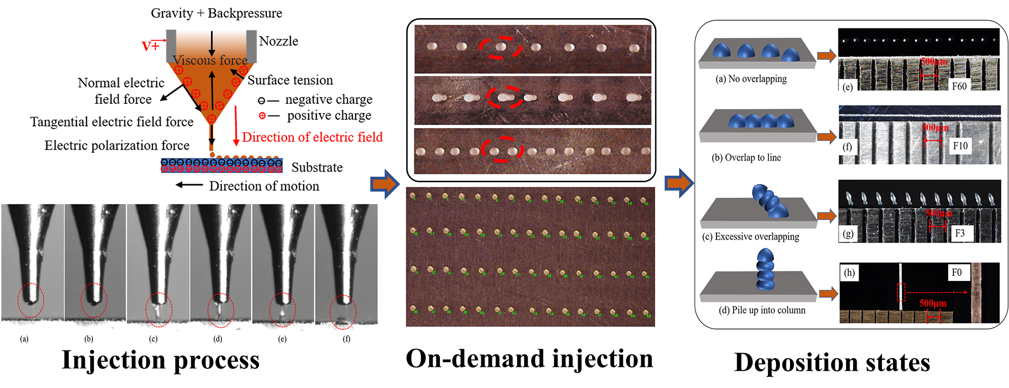
The properties of droplets produced by existing on-demand injection systems are typically determined by the nozzle diameter, i.e., only droplets with size larger than this diameter can be obtained. To solve this problem, a system for electric field-driven droplet injection and deposition was developed, and the related performances were compared with those of a standard pneumatic system. The results show that the diameter of droplets generated accordingly can be significantly smaller than the nozzle diameter. In particular, the effects of frequency and duty ratio on the number of droplets were studied by assuming microcrystalline wax as work material. A deposition matrix was obtained by using a nozzle with a diameter of 200 μm. The average diameter of the matrix was 80.17 μm with a standard deviation of 2.65 μm and the average spacing was 301.25 μm with a standard deviation of 6.80 μm. Four deposition states after droplet injection were considered and verified under different velocities of F60, F10, F3, and F0. We also provide an explanation for the existence of a series of inclined columns showing up during the deposition processs.Graphic Abstract
Keywords
Micro-droplet injection technology is a non-contact additive manufacturing technology, which is divided into continuous Ink-Jet (CIJ) technology and drop-on-demand (DOD) injection technology [1] according to the different principles of droplet generation. Compared with CIJ technology, DOD technology has better controllability of individual micro-droplet and has been widely used in material forming [2,3], micro-electromechanical systems [4,5], bio-medicine [6,7], and aerospace [8].
On-demand injection technologies are mainly classified as the piezoelectric, pneumatic, thermal bubble, and aerosol [9–11]. Since the first three technologies generate droplets by “squeezing”, the droplet size is limited by the nozzle diameter. If the nozzle diameter is excessively reduced, the additional pressure of surface tension and fluid flow in the nozzle resistance will increase significantly, increasing the processing cost and easily causing the phenomenon of nozzle clogging. Although the aerosol droplet on-demand injection technology can eject droplets smaller than the nozzle diameter, it is difficult to perform accurate pattern printing due to its lag in the adjustment of airflow parameters.
Contrary to the above four technologies, electrohydrodynamic jet (E-jet) printing [12,13] has the advantages of simple structure, low probability of plugging, high resolution, and wide application, showing great application prospects and setting off a research boom around the world. Seong et al. [14] fabricated transparent grid electrodes with a spacing of 100 μm and line width of 7 μm on the spherical glass surface using E-jet printing, which ensured high transmittance and good electrical properties. Lian et al. [15] made a novel drug release device for local tumor treatment using electrohydrodynamic near-field direct writing technology. Fuchs et al. [16] obtained biological scaffolds with different pore sizes through electro-hydrodynamic 3D printing technology to study cell growth. Xu et al. [17] reported a new type of multi-layer fiber mat with a directional liquid transport function. The mat was prepared by electrohydrodynamic electrospinning technology and showed great prospects in the field of sportswear spinning. Li et al. [18] suppressed the residual oscillation of the meniscus by optimizing waveform design, improving the stability and uniformity of electrohydrodynamic on-demand printing. Lee et al. [19] developed a miniature supercapacitor (MSC) by electro-fluid printing on a chip, which has a much higher surface density than previously produced by printing. Kang et al. [20] prepared MAPbBr3 Perovskite/Piezoelectric composite micropatterns by electrohydrodynamic jetting, which have great potential in flexible transparent electrodes. Wang et al. [21,22] introduced coaxial-focused electro-hydrodynamic injection printing of semiconductor sub-microwires with large areas and high alignment, based on which a number of high-performance OFET devices were prepared. Im et al. [23] prepared microlens arrays using on-demand hydrodynamic jet printing, which have a shorter focal length, higher numerical aperture, and smaller f number.
Although electro-hydrodynamic spray has many advantages, the technology applies a high-voltage pulse power supply between the conductive nozzle and the conductive substrate. The distance between the conductive nozzle and the ground electrode constantly changes with the printing height, leading to a constant change in the electric field force. Therefore, the height of the nozzle and the substrate (printing bed) is generally not more than 3 mm; otherwise, it is difficult to form a stable cone jet. Moreover, when printing conductive materials, short circuits, and discharge can easily occur due to the residual charge [24], leading to great limitations in the printing range and stability. To solve this problem, Zhang et al. [25–29] improved electrohydrodynamic jet printing technology and carried out research in the fields of transparent electrodes, biological scaffolds, and flexible hybrid electronics. This technology only needs to connect the print nozzle to the positive pole of the high-voltage power supply without the need for a grounded counter electrode. The distance between the nozzle and the substrate (or the printed entity) is kept constant by reasonably controlling the thickness of the printing layer to ensure the formation of a stable electric field between the two. Consequently, the stability and reliability of the printing process are ensured, eliminating the limitation of the printing size.
Microcrystalline wax is a cheap and easily removed material often used to make wax molds. However, the accuracy of the traditional wax mold printing process is limited by nozzles. In this study, a high-precision droplet on-demand injection deposition technology is proposed. The differences between the injection process and the pneumatic injection process were compared by setting up an electric field-driven droplet on-demand injection experimental system. The effects of frequency and duty ratio on the number of droplets dropped during the injection process were studied using microcrystalline wax as experimental material. The dot matrix and pattern printing of droplets are realized, and four deposition states of droplets are proposed and verified. This research technique breaks through the limitation of nozzle diameter and provides a new method for the fabrication of high-precision microstructures.
2 Comparison of Process Principles
2.1 Mainstream On-Demand Injection
The working principle of the current mainstream on-demand injection technology is shown in Fig. 1. The piezoelectric type relies on piezoelectric ceramics to bend and deform as the voltage changes to push the ink droplets out of the nozzle. The pneumatic type is formed by a certain gas pressure with the help of the solenoid valve to form a gas pulse. The change in the nozzle pressure will squeeze the ink ejection. The hot air bubble is heated by the applied voltage to the film resistor, and the ink is vaporized, aggregated, expanded, and extruded from the nozzle. The above three all produce droplets by “squeezing”. Aerosol type converts ink gas into aerosol under the action of ultrasonic wave and shoots it from the nozzle under the drive of high-speed inert gas, which often causes more satellite droplets around the main body of the print.
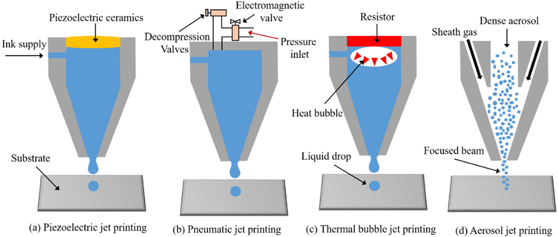
Figure 1: The principle of the current mainstream on-demand injection technology
2.2 Electric Field-Driven Droplet On-Demand Injection
The electric field-driven droplet on-demand injection deposition technology stimulates the required electric field by electrostatic induction, the principle of which is shown in Fig. 2. No high voltage was added at the initial stage. The liquid at the nozzle appears in the shape of a half-moon and remains stable under the combined action of air pressure, gravity, surface tension, and viscous force, as shown in Fig. 2a. The conductive nozzle has a high potential when connected to the positive pole of the pulsed DC power supply, which makes the surface of the half-moon droplet collect a positive charge. When the platform moves so that the nozzle is close to the substrate (conductive or not), the upper surface of the substrate close to the nozzle accumulates negative charges, while the lower surface away from the nozzle accumulates positive charges due to the effect of electrostatic induction. At this time, a stable electric field is formed between the printing nozzle and the substrate, as shown in Fig. 2b, and the electric field strength increases with the DC power supply voltage. When the electric field strength increases to a certain value, the half-moon is gradually stretched and lengthened to form a Taylor cone under the combined action of back pressure, electric field force, gravity, surface tension, and viscous force. An extremely fine cone jet is generated at the tip when the electric field force continues to increase and breaks through the surface tension and viscous force. The jet time is very short, i.e., when the high-pulse voltage disappears, the jet immediately stops. The jet that has been ejected retracts into a single droplet under the action of surface tension and is deposited at a specific position on the substrate according to the movement of the platform.
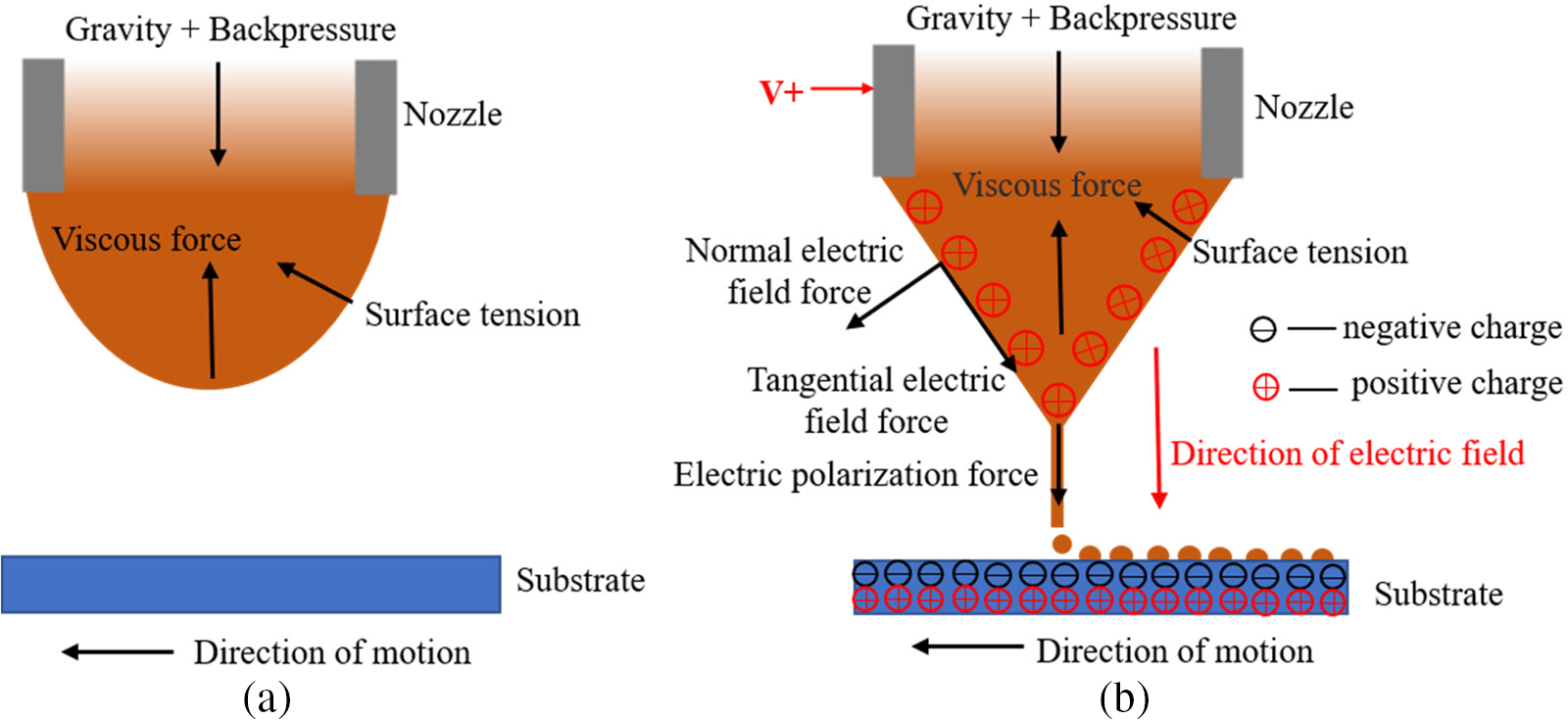
Figure 2: The principle of electric field-driven droplet on-demand injection deposition
According to Fig. 2, the solution is subject to the coupling effect of the electric field and flow field in the ejection process. The dynamic current generated in an electrohydrodynamic field is very small, i.e., this process can be regarded as an electrostatic process [30]:
There are conductors and dielectric materials in the electric field. Hence, the Gauss theorem can be expressed as follows:
In this electrostatic process, the charge inflow and outflow satisfy the charge conservation equation:
Eqs. (1)–(3) are electric field governing equations, where
According to the above analysis, the external forces on the droplets at the nozzle mainly include electric field force, gravity, surface tension, viscous force, and pressure. The law of conservation of momentum is expressed by the Navier-Stokes equation as follows [31]:
Eqs. (4) and (5) are the governing equations of the flow field, where
An experimental system was developed according to the process principle of electric field-driven droplet on-demand spray deposition, and its schematic diagram is shown in Fig. 3. The system is mainly composed of four parts: temperature regulation control module, micro-droplet injection module, motion control module, and high-speed monitoring module. The temperature control module mainly includes a customized glass crucible cylinder, a nozzle heating block, an annular ceramic heating furnace, and two temperature controllers (SY-TF9-RB10). The module uses a temperature controller to precisely control the heating temperature of the annular ceramic heating furnace and the nozzle heating block, providing stable temperature conditions for the injection process. The temperature control accuracy can reach ±0.5°C. The Microdroplet injection module is the core of the device, which mainly includes a high voltage power supply (DWP-P352-1ACF0), a signal generator (FY3200S), an air pump (ZP-KYJ-002), a precision pressure regulating valve (IR2020-02BG), and a nozzle (stain-less steel precision Musashi needle). This module can produce a very fine conical jet, and a single droplet is formed after the jet breaks. The motion control module mainly includes a three-axis motion platform (FSD-PT441). The repeated positioning accuracy of the moving platform is ±0.02 mm. The man-machine control software is developed by Otostudio, which controls the precise deposition of the ejection droplets onto the substrate according to the pulse voltage frequency, pulse width, and movement speed of the platform. When a layer of printing is completed, the nozzle moves up with the thickness of the section of the Z axis to continue the printing. The high-speed monitoring module can observe and record the nonlinear dynamic process of droplet spraying, falling, and deposition in real-time. The module mainly includes a high-performance computer, a high-speed CCD camera (CSC6M100CMP11), a high-speed image acquisition card (AS-FBD-1XCLD-2PE4), a stroboscope (N61-DT-2350PE), a synchronous trigger, and a digital electron microscope (ZT1951).
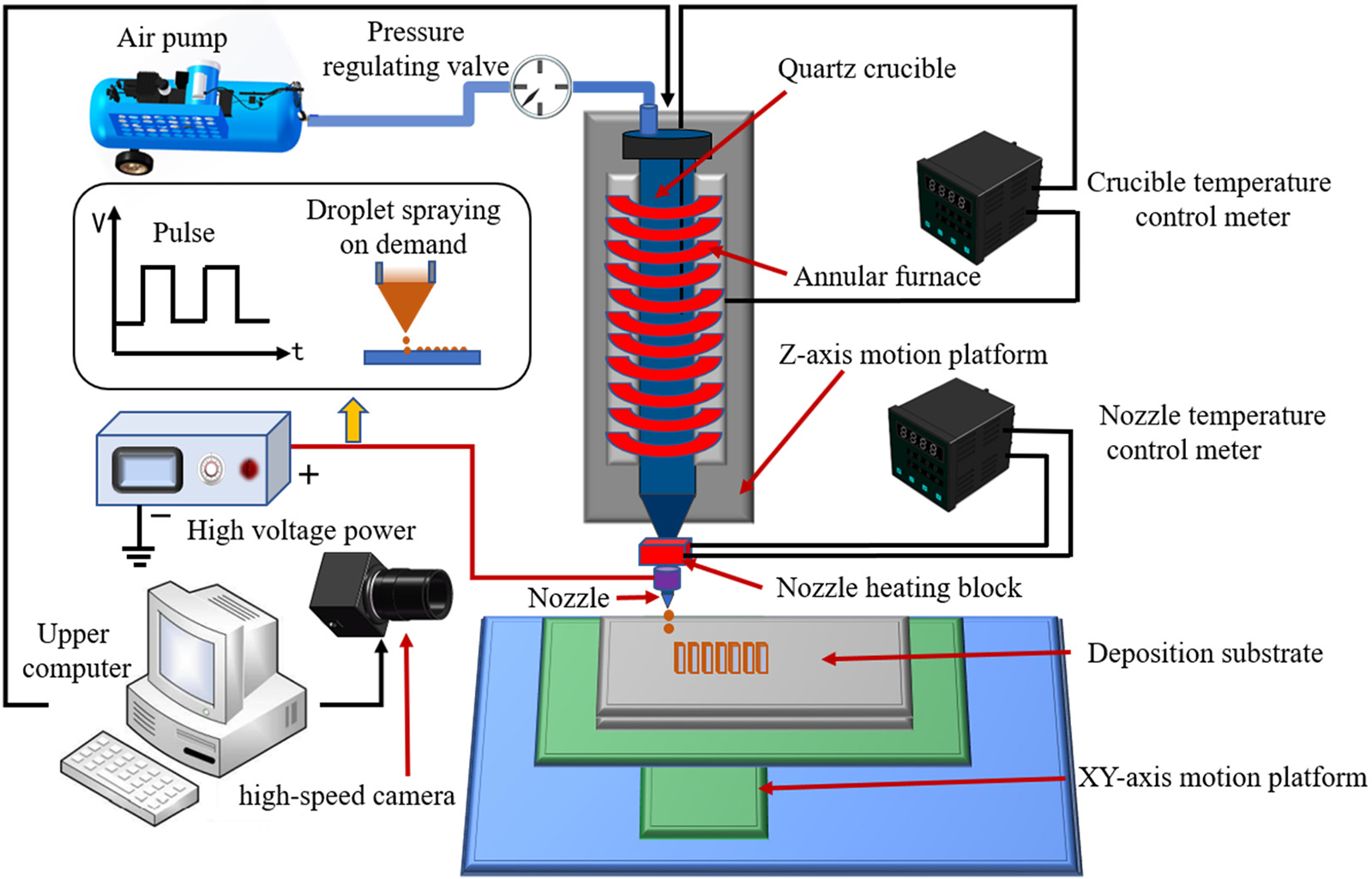
Figure 3: Schematic diagram of the electric field-driven droplet on-demand jet deposition experimental system
4 Experiment Results and Discussion
4.1 Comparison of the Injection Process
Fig. 4 shows the process of pneumatic injection on demand. During the experiment, the air pressure is 25 kPa, and the inner diameter of the nozzle is 200 μm. The nozzle structure is shown in Fig. 4a. No pressure was applied at the initial stage, and there was no droplet hanging from the nozzle under the action of liquid surface tension and viscous force, as shown in Fig. 4b. When the pulse pressure is applied to the nozzle, the liquid in the inner cavity of the nozzle is squeezed out under the action of the pulse pressure, forming a liquid column with a circular end face, as shown in Fig. 4c. Fig. 4d shows that the pressure in the cavity drops after the liquid is ejected. The flow velocity of the liquid column near the nozzle also drops, while the first ejected liquid column still moves at a higher speed, resulting in the continuous elongation of the liquid column and a shrinking neck effect. In Fig. 4e, the liquid column at the shrinking neck is constantly stretched and thinned under the action of surface tension, finally breaking to form a single columnar microdroplet. As shown in Figs. 4f and 4g, the liquid column after nozzle fracture is pulled back to the nozzle under the combined action of the negative pressure and the surface tension. A single columnar microdroplet gradually shrinks back into a ball under the action of the surface tension, forming droplets with a diameter larger than the nozzle diameter.
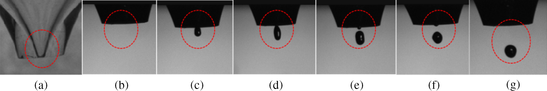
Figure 4: Pneumatic droplet on-demand injection process
Fig. 5 shows the on-demand injection process of a droplet driven by the electric field. The experimental voltage is 1500 V, the pulse frequency is 1 Hz, the inner diameter of the nozzle is 200 μm, and the outer diameter is 350 μm. When no high voltage is added, the droplet is suspended at the nozzle in the shape of a half-moon and remains stable under the action of back pressure, as shown in Fig. 5a. Once the high-voltage power supply is connected, the height of the half-surface is continuously stretched and lengthened under the action of electric field force, forming a Taylor cone shown in Fig. 5b. With an increase in the electric field intensity, Taylor’s cone is further stretched to produce an extremely fine cone jet, and Figs. 5c–5e show that the ejected jet rears and breaks into a single droplet at the bottom. The diameter of a single formed droplet is smaller than that of the nozzle, and it is deposited towards the substrate surface at high speed. In Fig. 5f, the cone jet disappeared, the liquid level at the nozzle returned to the minimum height, and the single injection deposition was completed to prepare for the next injection.
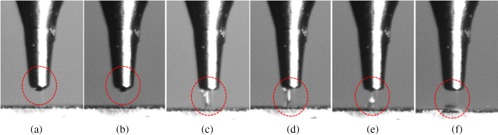
Figure 5: Electric field-driven droplet on-demand injection process
Both of the above two injection processes have an energy storage phase, and the formation of droplets is related to the necking effect of the jet. However, it is obvious that there is no “Taylor cone” formation in the process of pneumatic on-demand injection, and the diameter of the droplet formed is significantly larger than the inner diameter of the nozzle. The on-demand droplet injection process driven by a high-voltage electric field has a complete cycle of Taylor cone formation, stretching, spraying, and recovery. Lastly, the diameter of the formed droplet is significantly smaller than the inner diameter of the nozzle.
The pulse width should be equal to the time required for injection to achieve single pulse on-demand injection, i.e., one pulse only produces one droplet. Moreover, different pulse widths affect the number of droplets. Pulse width is jointly determined by frequency and duty ratio. Different pulse frequencies need to match different duty ratios to improve the printing accuracy and achieve single pulse on-demand injection. In the experiment, microcrystalline wax (No. 80) was used as the material, and two different frequencies were selected during the process. The experimental parameters are shown in Table 1, and the results are shown in Fig. 6.

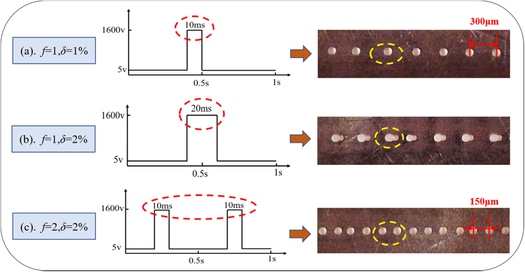
Figure 6: Droplet deposition morphology at different frequencies and duty cycles
In Fig. 6a, the pulse width of 10 ms is equal to the injection time, achieving the on-demand injection of one pulse and one droplet. The size of the deposited droplet is uniform, the spacing is consistent, and the center distance of the drop point is 300 μm. The moving speed of the platform remained unchanged. The pulse width increased from 10 to 20 ms with an increase in the duty ratio. At this time, the pulse width was equal to twice the injection time, and the phenomenon of two droplets under one pulse occurred, as shown in Fig. 6b. This may be because the action time of the electric field becomes longer with an increase in pulse width. After forming a cone jet, the half-moon surface does not return to its initial shape without adding an electric field. The Taylor cone produces a jet again, affecting the printing stability. When the pulse frequency increased, the pulse width in Fig. 6c was the same as that in Fig. 6a, i.e., 10 ms. The printing resumed in the single-pulse single-drop mode, and the center distance of the drop point was reduced by half to 150 μm with an increase in frequency.
According to the above experimental analysis, the upper computer controls the moving trajectory of the nozzle under the experimental conditions in Fig. 6a, and the droplet deposition dot matrix shown in Fig. 7 is obtained. It can be seen from the figure that the wax droplets deposited on the copper-clad plate are regular in shape and uniform in size, and the droplet spacing is consistent. The professional image analysis and measurement software Image Pro was used to measure the diameter of 60 wax droplets and the spacing of 56 adjacent droplets in the figure. Each droplet’s diameter and spacing were measured three times, and the average value was taken as the final measurement result with a measurement error of ±0.01 μm.
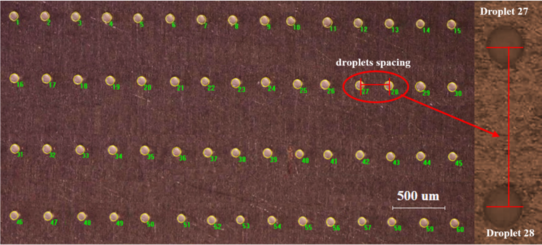
Figure 7: Dot matrix of wax droplets deposited on the copper-clad plate
Fig. 8 shows the diameter distribution of wax droplets deposited on the copper-covered plate. The minimum diameter of wax droplets is 76.92 μm, the maximum diameter is 84.14 μm, the average diameter of wax droplets is approximately 80.17 μm, the standard deviation is 2.65 μm, and the percentage of wax droplet diameter to nozzle diameter is 40.10%. This indicates that the wax droplets are uniform in size, and the droplet diameter is one order of magnitude smaller than the nozzle diameter. There is a slight deviation in the diameter of the droplet, which may be caused by the unstable airflow of the backpressure system in conjunction with the electrical system. The airflow change will make the meniscus at the end of the nozzle fluctuate in a small range and eventually lead to the deviation of droplet diameter after the jet. Fig. 9 shows the spacing distribution between adjacent wax droplets. The minimum distance between adjacent wax droplets is 286.05 μm, the maximum is 313.95 μm, the average spacing is 301.25 μm, and the standard deviation is 6.80 μm. The droplet spacing error is mainly caused by two aspects. The first is the inconsistency of deposition points caused by shock when the mobile platform is used in couple with the electrical system. The second is the time delay when the back pressure system and the mobile platform are used together with the electrical system.

Figure 8: Distribution of wax droplets diameter
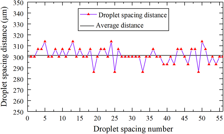
Figure 9: Distribution of adjacent wax droplets spacing
The experimental system was stable, and the obtained droplets were uniform in size and spacing. The pattern of “Xuchang University” was designed with a font size of 14.5 mm × 3.5 mm, the generated print path code was imported into the control software of the experimental system, and the patterned printing was completed, as shown in Fig. 10.
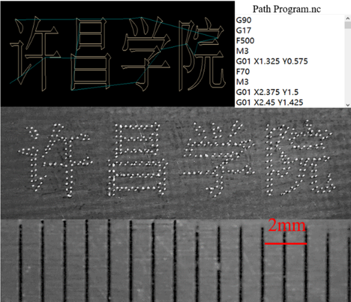
Figure 10: Patterned printing of “Xuchang University”
The center distance between two adjacent droplets significantly affects the final deposition states of the droplets. As shown in Fig. 11,
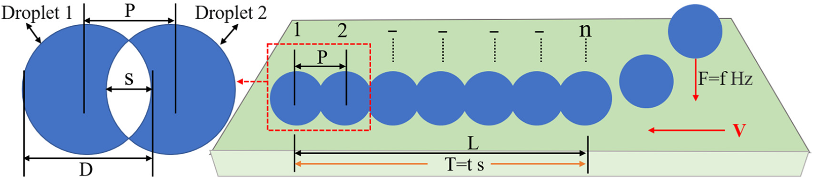
Figure 11: Droplet spacing and overlap rate during deposition
When the droplet diameter and ejection frequency remain unchanged, the center distance
First, when
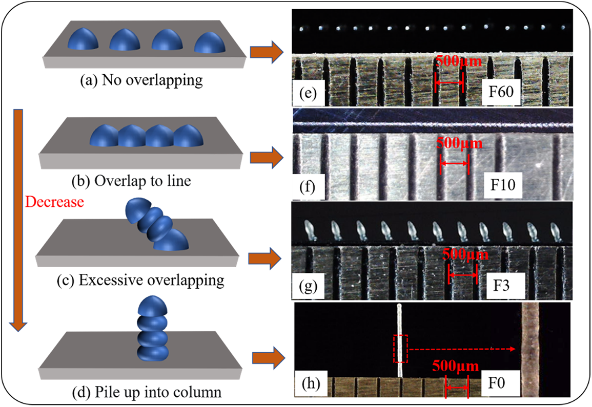
Figure 12: Different states of droplet deposition at various velocities
Second, when the v value decreases appropriately, the center distance
Third, when
Finally, when
The deposition morphology of the above four droplets was obtained under the experimental conditions in Table 2, during which the motion velocity of the experimental platform was adjusted as F60, F10, F3, and F0. When the deposition platform movement is F60, there is no overlap between droplets, and the droplets are uniform in size and spacing, as shown in Fig. 12e. When the deposition platform moves at the velocity of F10, the adjacent droplets are partially fused, forming a straight line with good linearity, as shown in Fig. 12f. When the deposition platform moves at F3 velocity, there is excessive overlap between the adjacent droplets, and the droplets are deposited diagonally upward to form a series of inclined columns. These columns have the same shape, and their spacing and tilt angles are consistent, as shown in Fig. 12g. When the deposition platform stopped and the nozzle moved vertically upward, the droplets deposited and accumulated downward continuously, forming a microcylinder with a large ratio of height to the diameter that had a smooth surface and uniform diameter, as shown in Fig. 12h.

Fig. 13a shows the principle of producing the inclined column. Generally, the electric field force generated by the closest distance between the substrate and the nozzle is straight down. However, when the moving speed of the substrate is too low, the distance between the nozzle and the deposited surface will be shorter if there are deposited droplets on the substrate. Moreover, the electric field intensity generated by the electrostatic induction between them will be greater, causing the direction of the electric field force to be deflected by the deflection angle α. At this time, the droplets ejected from the nozzle will move diagonally toward the deposited entity surface and deposit. The distance between the nozzle and the deposited entity keeps increasing with the continuous movement of the substrate. When the substrate exerts more force on the droplets at the nozzle than the deposited entity, the deposited entity will not continue to grow. Once the droplets at the nozzle are sprayed and deposited on the substrate again, a new cycle begins. The angle between the formed cylinder and the substrate is deposition angle β. Figs. 13b–13e show this process.
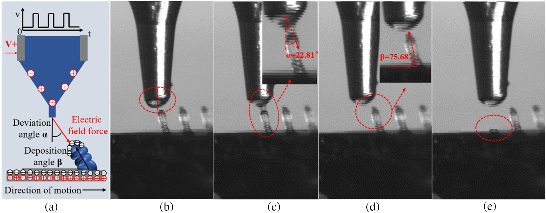
Figure 13: Formation principle and process of excessive overlapping
Fig. 13b shows that the droplet at the nozzle is no longer a center-symmetric meniscus but gathers on the left side of the nozzle center. This is because when the applied pulse voltage is at a low electric level, the electric field force between the nozzle and the deposited entity surface will suddenly disappear. Hence, the droplet will oscillate back and forth after the sudden loss of the electric field force. In Fig. 13c, a Taylor cone is formed, and a cone jet occurs. The jet direction is inclined towards the deposited cylinder surface, and the deflection angle measured at this time is 22.81°. Fig. 13d shows that the jet has stopped and completed a single injection, forming an inclined cylinder with a deposition angle β of 75.68°, and the substrate moved some distance to the right. As shown in Fig. 13e, the distance of the substrate moving to the right increases, and the electric field force formed by the nozzle and the inclined cylinder surface weakens. At this time, the force of the substrate on the nozzle droplets exceeds that of the deposited cylinder, and the droplets at the nozzle are sprayed and deposited on the substrate once again.
1. The experimental system of electric field-driven on-demand injection deposition was developed based on the analysis of the principle of on-demand injection. The injection process was observed and compared with the aerodynamic model. It was observed that the Taylor cone is formed, and a very thin cone jet is generated during the on-demand ejection process driven by the electric field. Lastly, the diameter of the droplets generated after neck shrinking is smaller than that of the nozzle.
2. The effects of frequency and duty ratio on the number of drops during the injection process were studied using microcrystalline wax. The on-demand controlled injection of droplets was realized.
3. A deposition matrix was obtained using a nozzle with an inner diameter of 200 μm. The average diameter of the matrix was 80.17 μm with a standard deviation of 2.65 μm, while the average spacing was 301.25 μm with a standard deviation of 6.80 μm. In addition, the “Xuchang University” pattern was printed on demand. The experimental results show that the droplets have uniform size and consistent spacing, and their diameters are one order of magnitude smaller than the nozzle diameter.
4. Four deposition states after droplet injection were proposed and verified under different velocities of F60, F10, F3, and F0. The reasons for a series of inclined columns in the deposition process were explained, and their processes were observed.
Funding Statement: This project is supported by the National Science Foundation of China (Grant Nos. 51305128, 52005059), Open Research Fund of State Key Laboratory of High-Performance Complex Manufacturing, and Central South University (Grant No. Kfkt2020-10), and Key Scientific Research Project of Xuchang University (No. 2023ZD001).
Conflicts of Interest: The authors declare that they have no conflicts of interest to report regarding the present study.
References
1. Chao, Y., Yi, H. (2021). Experimental analysis of a pneumatic drop-on-demand (DOD) injection technology for 3D printing using a gallium-indium alloy. Fluid Dynamics & Materials Processing, 17(3), 587–595. https://doi.org/10.32604/fdmp.2021.015478 [Google Scholar] [CrossRef]
2. Prokhorov, V. E. (2020). Acoustic shock emission in a collision of a drop with water surface. Fluid Dynamics & Materials Processing, 16(4), 737–746. https://doi.org/10.32604/fdmp.2020.08988 [Google Scholar] [CrossRef]
3. Gilani, N., Aboulkhair, N. T., Simonelli, M., East, M., Ashcroft, I. et al. (2021). Insights into drop-on-demand metal additive manufacturing through an integrated experimental and computational study. Advanced Materials, 48(12), 102402. https://doi.org/10.1016/j.addma.2021.102402 [Google Scholar] [CrossRef]
4. Can, T. T. T., Kwack, Y. J., Choi, W. S. (2021). Drop-on-demand patterning of MoS2 using electrohydrodynamic jet printing for thin-film transistors. Materials & Design, 199(1), 109408. https://doi.org/10.1016/j.matdes.2020.109408 [Google Scholar] [CrossRef]
5. Yuk, H., Lu, B. Y., Lin, S., Qu, K., Xu, J. K. et al. (2020). 3D printing of conducting polymers. Nature Communications, 11(1), 1–8. https://doi.org/10.1038/s41467-020-15316-7 [Google Scholar] [PubMed] [CrossRef]
6. Ebrahimi Orimi, H., Hosseini Kolkooh, S. S., Hooker, E., Narayanswamy, S., Larrivée, B. et al. (2020). Drop-on-demand cell bioprinting via laser induced side transfer (LIST). Scientific Reports, 10(1), 9730. https://doi.org/10.1038/s41598-020-66565-x [Google Scholar] [PubMed] [CrossRef]
7. Utama, R. H., Tan, V. T., Tjandra, K. C., Sexton, A., Nguyen, D. H. et al. (2021). A covalently crosslinked ink for multimaterials drop-on-demand 3D bioprinting of 3D cell cultures. Macromolecular Bioscience, 21(9), 2100125. https://doi.org/10.1002/mabi.202100125 [Google Scholar] [PubMed] [CrossRef]
8. Elkaseer, A., Schneider, S., Deng, Y., Scholz, S. G. (2022). Effect of process parameters on the performance of drop-on-demand 3D inkjet printing: Geometrical-based modeling and experimental validation. Polymers, 14(13), 2557. https://doi.org/10.3390/polym14132557 [Google Scholar] [PubMed] [CrossRef]
9. Abbas, Z., Wang, D. Z., Lu, L. K., Du, Z. L., Zhao, X. Y. et al. (2022). The focused electrode ring for electrohydrodynamic jet and printing on insulated substrate. International Journal of Precision Engineering and Manufacturing, 23(5), 545–563. https://doi.org/10.1007/s12541-022-00634-1 [Google Scholar] [CrossRef]
10. Huang, J. D., Segura, L. J., Wang, T. J., Zhao, G. L., Sun, H. Y. et al. (2020). Unsupervised learning for the droplet evolution prediction and process dynamics understanding in inkjet printing. Additive Manufacturing, 35(6), 101197. https://doi.org/10.1016/j.addma.2020.101197 [Google Scholar] [CrossRef]
11. Bernasconi, R., Brovelli, S., Viviani, P., Soldo, M., Giusti, D. et al. (2022). Piezoelectric drop-on-demand inkjet printing of high-viscosity inks. Advanced Engineering Materials, 24(1), 2100733. https://doi.org/10.1002/adem.202100733 [Google Scholar] [CrossRef]
12. Sieber, I., Zeltner, D., Ungerer, M., Wenka, A., Walter, T. et al. (2022). Design and experimental setup of a new concept of an aerosol-on-demand print head. Aerosol Science and Technology, 56(4), 355–366. https://doi.org/10.1080/02786826.2021.2022094 [Google Scholar] [CrossRef]
13. Kim, S., Lee, S. E., Kim, B. H. (2022). Micropattern arrays of polymers/quantum dots formed by electrohydrodynamic jet (e-jet) printing. Journal of the Korean Institute of Electrical and Electronic Material Engineers, 35(1), 18–23. https://doi.org/10.4313/JKEM.2022.35.1.3 [Google Scholar] [CrossRef]
14. Seong, B., Yoo, H., Nguyen, V. D., Jang, Y., Ryu, C. (2014). Metal-mesh based transparent electrode on a 3-D curved surface by electrohydrodynamic jet printing. Journal of Micromechanics and Microengineering, 24(9), 097002. https://doi.org/10.1088/0960-1317/24/9/097002 [Google Scholar] [CrossRef]
15. Lian, H., Meng, Z. X. (2017). Melt electrospinning of daunorubicin hydrochloride-loaded poly (ε-caprolactone) fibrous membrane for tumor therapy. Bioactive Materials, 2(2), 96–100. https://doi.org/10.1016/j.bioactmat.2017.03.003 [Google Scholar] [PubMed] [CrossRef]
16. Fuchs, A., Youssef, A., Seher, A., Hochleitner, G., Dalton, P. D. et al. (2019). Medical-grade polycaprolactone scaffolds made by melt electrospinning writing for oral bone regeneration–A pilot study in vitro. BMC Oral Health, 19(28), 1–11. https://doi.org/10.1186/s12903-019-0717-5 [Google Scholar] [PubMed] [CrossRef]
17. Xu, J. H., Xin, B. J., Chen, Z. M., Liu, Y., Zheng, Y. S. et al. (2019). Preparation and characterization of multilayered superfine fibrous mat with the function of directional water transport. RSC Advances, 9(29), 16754–16766. https://doi.org/10.1039/C9RA00996E [Google Scholar] [PubMed] [CrossRef]
18. Li, H., Yang, W., Duan, Y., Chen, W., Zhang, G. et al. (2022). Residual oscillation suppression via waveform optimization for stable electrohydrodynamic drop-on-demand printing. Additive Manufacturing, 55(34), 102849. https://doi.org/10.1016/j.addma.2022.102849 [Google Scholar] [CrossRef]
19. Lee, K. H., Lee, S. S., Ahn, D. B., Lee, J., Byun, D. et al. (2020). Ultrahigh areal number density solid-state on-chip microsupercapacitors via electrohydrodynamic jet printing. Science Advances, 6(10), eaaz1692. https://doi.org/10.1126/sciadv.aaz1692 [Google Scholar] [PubMed] [CrossRef]
20. Kang, G., Lee, H., Moon, J., Jang, H. S., Cho, D. H. et al. (2022). Electrohydrodynamic jet-printed MAPbBr3 perovskite/polyacrylonitrile nanostructures for water-stable, flexible, and transparent displays. ACS Applied Nano Materials, 5(5), 6726–6735. https://doi.org/10.1021/acsanm.2c00753 [Google Scholar] [CrossRef]
21. Wang, D., Lu, L., Zhao, Z., Zhao, K., Zhao, X. et al. (2022). Large area polymer semiconductor sub-microwire arrays by coaxial focused electrohydrodynamic jet printing for high-performance OFETs. Nature Communications, 13(1), 6214. https://doi.org/10.1038/s41467-022-34015-z [Google Scholar] [PubMed] [CrossRef]
22. Lu, L., Wang, D., Zhao, Z., Li, Y., Pu, C. et al. (2023). Optimized coaxial focused electrohydrodynamic jet printing of highly ordered semiconductor sub-microwire arrays for high-performance organic field-effect transistors. Nanoscale, 15(4), 1880–1889. https://doi.org/10.1039/D2NR06469C [Google Scholar] [PubMed] [CrossRef]
23. Im, B., Prasetyo, F. D., Yudistira, H. T., Khalil, S. M., Cho, D. H. et al. (2023). Drop-on-demand electrohydrodynamic jet printing of microlens array on flexible substrates. ACS Applied Polymer Materials, 5(3), 2264–2271. https://doi.org/10.1021/acsapm.3c00054 [Google Scholar] [CrossRef]
24. Liashenko, I., Rosell-Llompart, J., Cabot, A. (2020). Ultrafast 3D printing with submicrometer features using electrostatic jet deflection. Nature Communications, 11(1), 753. https://doi.org/10.1038/s41467-020-14557-w [Google Scholar] [PubMed] [CrossRef]
25. Zhang, G. M., Lan, H. B., Qian, L., Zhao, J. W., Wang, F. (2020). A microscale 3D printing based on the electric-field-driven jet. 3D Printing and Additive Manufacturing, 7(1), 37–44. https://doi.org/10.1089/3dp.2018.0154 [Google Scholar] [PubMed] [CrossRef]
26. Wang, Z., Zhang, G. M., Huang, H., Qian, L., Liu, X. L. et al. (2021). The self-induced electric-field-driven jet printing for fabricating ultrafine silver grid transparent electrode. Virtual and Physical Prototyping, 16(1), 113–123. https://doi.org/10.1080/17452759.2020.1823116 [Google Scholar] [CrossRef]
27. Zhu, X. Y., Xu, Q., Li, H. K., Liu, M. Y., Li, Z. H. et al. (2019). Fabrication of high-performance silver mesh for transparent glass heaters via electric-field-driven microscale 3D printing and UV-assisted microtransfer. Advanced Materials, 31(32), 1902479. https://doi.org/10.1002/adma.201902479 [Google Scholar] [PubMed] [CrossRef]
28. Zhu, X. Y., Liu, M. Y., Qi, X. M., Li, H. K., Zhang, Y. F. et al. (2021). Templateless, plating-free fabrication of flexible transparent electrodes with embedded silver mesh by electric-field-driven microscale 3D printing and hybrid hot embossing. Advanced Materials, 33(21), 2007772. https://doi.org/10.1002/adma.202007772 [Google Scholar] [PubMed] [CrossRef]
29. Huang, H., Zhang, G., Li, W., Yu, Z., Peng, Z. et al. (2023). The theoretical model and verification of electric-field-driven jet 3D printing for large-height and conformal micro/nano-scale parts. Virtual and Physical Prototyping, 18(1), e2140440. https://doi.org/10.1080/17452759.2022.2140440 [Google Scholar] [CrossRef]
30. Chen, J. Z., Wu, T., Zhang, L. B., Li, P., Feng, X. W. et al. (2019). Effect of process parameters on organic micro patterns fabricated on a flexible substrate using the near-field electrohydrodynamic direct-writing method. Micromachines, 10(5), 287. https://doi.org/10.3390/mi10050287 [Google Scholar] [PubMed] [CrossRef]
31. Abbas, Z., Wang, D. Z., Du, Z. Y., Zhao, K. P., Du, Z. L. et al. (2021). Numerical simulation of stable electrohydrodynamic cone-jet formation and printing on flexible substrate. Microelectronic Engineering, 237, 111496. https://doi.org/10.1016/j.mee.2020.111496 [Google Scholar] [CrossRef]
Cite This Article
 Copyright © 2023 The Author(s). Published by Tech Science Press.
This work is licensed under a Creative Commons Attribution 4.0 International License , which permits unrestricted use, distribution, and reproduction in any medium, provided the original work is properly cited.
 Downloads
 Citation Tools