
 Submit a Paper
 Propose a Special lssue
 Open Access
ARTICLE

Design and Fluid-Dynamic Analysis of a Flushing Nozzle for Drilling Applications
1
School of Petroleum Engineering, China University of Petroleum (East China), Qingdao, 266580, China
2
Drilling Technology Research Institute of Shengli Petroleum Engineering Co., Ltd., Sinopec, Dongying, 257000, China
3
Shenzhen South China Sea Oil Economic Development Company, Shenzhen, 518000, China
* Corresponding Author: Hongjian Ni. Email:
Fluid Dynamics & Materials Processing 2023, 19(12), 2953-2963. https://doi.org/10.32604/fdmp.2023.029491
Received 23 February 2023; Accepted 25 April 2023; Issue published 27 October 2023
 View Full Text
 Download PDF
Abstract
The actuator is a key component of the creaming tool in drilling applications. Its jet performances determine the effective reaming efficiency. In this work, a new selective reaming tool is proposed and the RNG k-ε turbulence model is used to calculate its internal and external flow fields. In particular, special attention is paid to the design of the flushing nozzle. The results show that the jet originating from the flushing nozzle has a significant influence on rock cutting and blade cooling effects. In turn, the jet performances depend on geometric structure of the creaming actuator. In this framework, a conical-cylindrical nozzle with a diameter of 7 mm is initially considered as a basis to implement a strategy to optimize the structural parameters of the reaming actuator, and improve the related side tracking reconstruction technology.Keywords
Reaming tool while drilling is a drilling technology that uses a reaming tool to increase the borehole size to larger than the inner diameter of the upper casing pipe while drilling [1,2]. In the drilling operations of deep and ultra-deep wells, the problems of small annular gap and low cementing quality in deep wells seriously restrict the exploitation of deep oil and gas resources [3,4]. Reaming while drilling technology has a wide range of applications and market prospects including in improving the cementing quality of hole, solving hole shrinkage, and dealing with complex downhole conditions. This technology can also reduce the number of drill-up and drill-down, and improve drilling efficiency [5]. As one of the reaming tools, reaming tool while drilling has an incomparable advantage over conventional fixed-wing reaming tools. Reaming tools while drilling have attracted the attention of researchers all over the world, which has driven the rapid development of reaming technology [6].
With the continuous exploitation of oil resources, most oil fields are generally in the middle and late stages of development, and windowed-side drilling directional wells have become an effective means to revive low-producing wells, discontinued wells, and abandoned wells [7]. Sidetrack drilling can greatly improve the extent of oil well reserves, tap the potential of oil and gas reservoirs, improve the production and recovery efficiency of a single well, and reduce the cost of reconstruction and development of old oil wells [8]. However, conventional cementing technology has the problem of poor cementing quality, which cannot meet the requirements of oil field development. The application of reaming while drilling technology can enlarge the hole of a sidetracking section and improve the completion quality of sidetracked wells, which has far-reaching significance to the application and popularization of sidetrack drilling [9,10].
Traditional reaming tools while drilling mainly open the blades by throwing a ball to generate expansionary force and close the blades by stopping the mud pump to generate resilience force [7]. Most of these reaming methods are single-stroke reaming, which can only open the reamer once in a single run, resulting in low reaming efficiency [11]. This paper proposes a new selective reaming tool while drilling, which can realize multiple opening and closing of downhole blades by controlling the displacement of the mud pump. The new reaming tool is hydraulically activated and has the function of selective reaming while drilling. Fig. 1 shows the diagram of when the blades of the reaming tool are activated.

Figure 1: Structural diagram of the selective reaming tool while drilling
The design of the reaming actuator is the core design part of the reaming tool while drilling. The quality of the design is directly related to the performance of the reaming tool while drilling and the success or failure of the reaming operation [12]. At present, most of the research on reaming tools still focus on the principle of reaming actuators, and the mechanical and hydraulic characteristics of reaming tools while drilling need to be further studied. Most reaming actuators are activated by the driving force generated by the hydraulic difference of the drilling fluid [13]. Therefore, it is necessary to study the characteristics of the internal and external flow field and pressure distribution of the selective reaming tool while drilling as the results can provide a theoretical basis for the structural design of the reaming actuator. At the same time, the flushing nozzle is one of the core components of the reaming actuator and is the key to the reaming tool’s ability to effectively clean the mud bag and carry rock cuttings, thus ensuring effective cutting of the formation to achieve borehole expansion [14,15]. Therefore, it is necessary to study the jet hydraulic characteristics of the flushing nozzle and optimize the nozzle structure, so as to improve the cleaning efficiency and the rate of penetration of the reaming drilling operation.
Regarding the current situation that the theory lags behind the practice in the selective reaming tool while drilling technology, this paper establishes a three-dimensional full-size physical model of the reaming tool while drilling. Computational fluid dynamics (CFD) is adopted to calculate the turbulent flow of the reaming tool while drilling, and the pressure field distribution and the velocity field distribution. Then, based on the established numerical simulation method, the effects of flushing nozzle type and nozzle diameter on the flux distraction and velocity distribution of blades are systematically analyzed. Finally, the structural parameters of the flushing nozzle are optimized based on the numerical simulation, which can provide technical support for selective reaming while drilling technology and guide the optimized design of the structural parameters of the reaming actuator. The research results are significant for improving the completion quality of sidetrack wells and the application and promotion of sidetracking reconstruction technology.
To simplify the numerical simulation, the nozzles of the drill bit are considered as being equivalent to a single nozzle [16]. The hydraulic diameter of the drill bit nozzles is equal to the cylinder section diameter of the equivalent nozzle and is set to 20 mm. Fig. 2 shows the axial sectional view of the selective reaming tool while drilling when it is activated. To reduce the number of calculations of the numerical simulation, the one-third symmetric model of the internal and external flow field of the reaming tool is selected as the calculation domain. The flow field calculation model and boundary conditions of the selective reaming tool while drilling is shown in Fig. 3.

Figure 2: Axial sectional view of the flow field when the creaming tool is activated
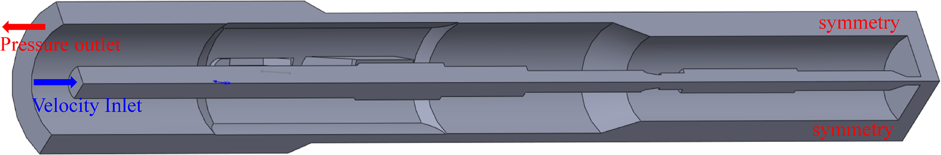
Figure 3: Flow field calculation model and boundary conditions of the selective reaming tool while drilling
The flow field characteristic of the reaming tool is a typical turbulent flow. At present, there are many turbulence models, but different models have certain limitations and applicable conditions [17,18]. In the numerical simulation of turbulence flow, the k-ε turbulence model is one of the most widely used, which can calculate the external flow of complex geometric structures [19]. In this paper, the RNG k-ε turbulence model is adopted to solve the turbulence field of the reaming tool. The control equations are:
where i, j are the coordinate direction and the direction of the velocity components, respectively; ui, uj are the speed of different coordinate directions, respectively; μ is the dynamic viscosity;
2.3 Boundary Conditions and Parameter Settings
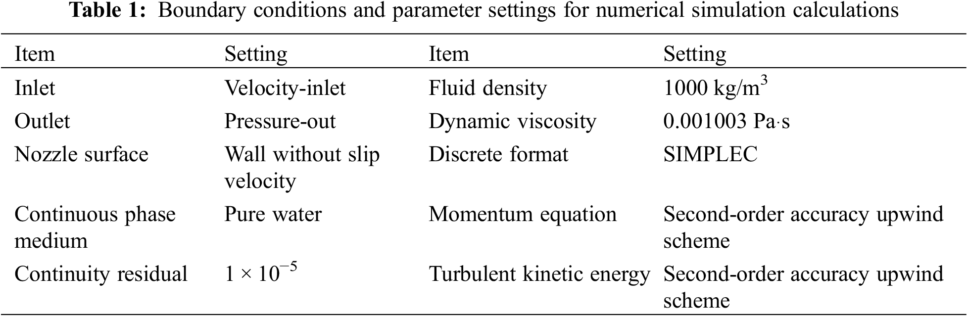
In order to compare the hydraulic characteristics of flushing nozzles with different geometric parameters and exclude the effect of other factors on the simulation results, the simulation calculations use the same set of parameters. The boundary conditions and parameter settings are given in Table 1.
The calculation mesh will directly affect the result of the calculational accuracy and computational time, and the grid number should be minimized on the premise of ensuring calculational accuracy [21]. To simulate a flow problem accurately, the appropriate grid needs to be meshed based on the practical problem. As shown in Fig. 3, a one-third symmetric model of the internal and external flow field of the reaming tool is selected as the calculation domain to reduce the computing time. The calculated field is meshed by the polyhedral grid and the boundary layer grid is used to define the local wall [22].
In this paper, the appropriate meshing strategy is determined by grid independence analysis. The influence of grid size on the pressure loss of the nozzle under different flow rates is given in Fig. 4. As the grid size decreases, the nozzle pressure drop increases slowly, and when the mesh size decreases to 2 mm, the nozzle pressure drop gradually tends to be stable. Therefore, to reduce the computing time, the grid size is determined to be 2 mm for the numerical simulation. The computational domain is divided into 1493482 grid cells. Fig. 5 shows the computational grid of the active reaming tool.
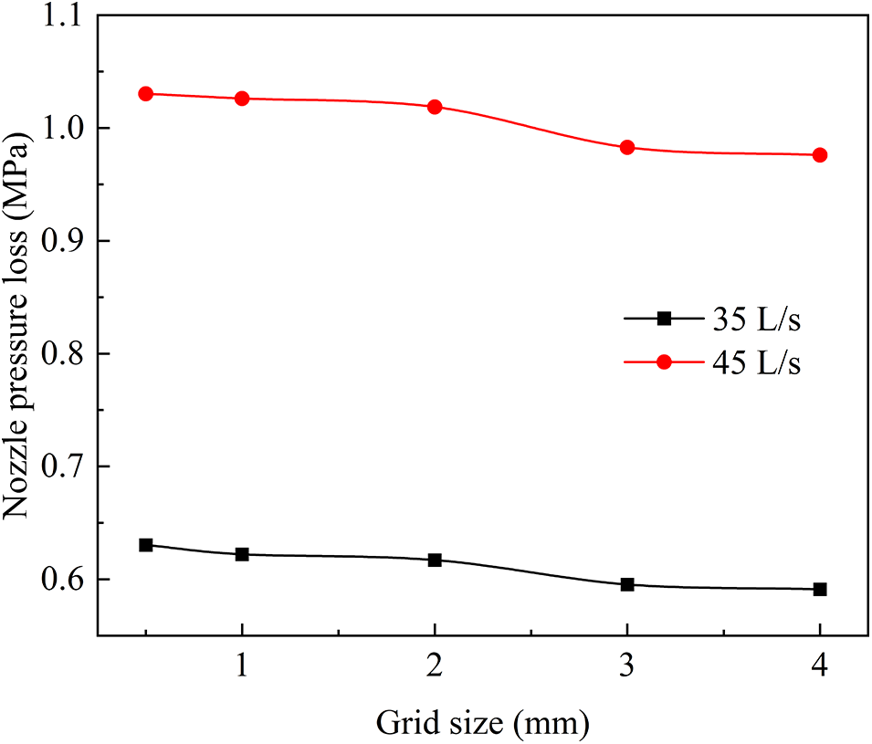
Figure 4: The influence of grid size on nozzle pressure loss
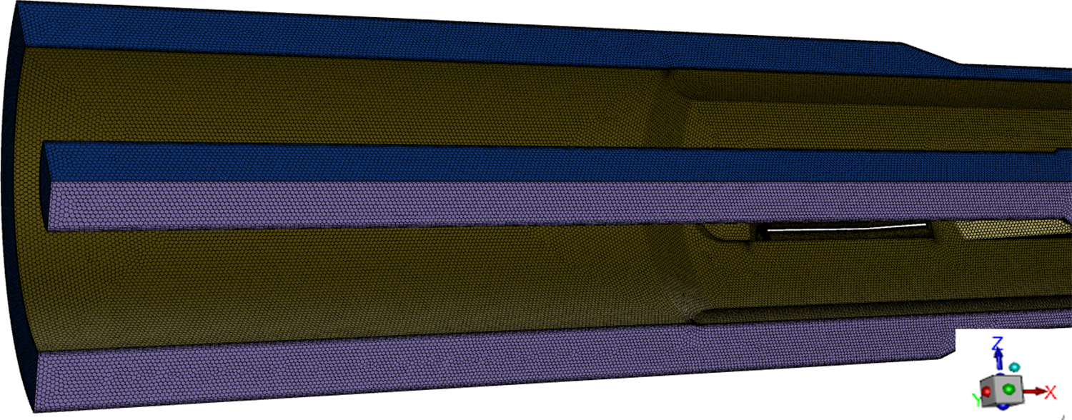
Figure 5: Computational grid when the reaming tool is active
Based on the established CFD turbulence model, the flow field characteristics of the selective creaming tool while drilling is analyzed first. Then, through single-factor analysis, the influence laws of the flushing nozzle type and nozzle diameter on the flux distraction and velocity distribution of blades are systematically studied to provide a theoretical basis for the structural optimization of the reaming actuator. In a drilling operation, the flow rate of the drilling fluid has a significant effect on the cleaning effect of rock cuttings. To ensure the efficient drilling of reaming tools, it is necessary to reasonably distribute the flux of the drill bit and flushing nozzle of the reaming tool. In this paper, the flow ratio of the drill bit is defined as:
where η is the flow ratio of the drill bit; Qbit and Qnozzle are the flux of the drill bit and flushing nozzles, respectively.
3.1 Analysis of Flow Field Characteristics
Under the numerical condition that the flow rate is 35 L/s, the flushing nozzle is a conical type, the nozzle diameter is 6 mm, and the angle between the nozzle axis and the reaming tool axis is 60°, the internal and annular flow field characteristics of the selective creaming tool while drilling is analyzed.
Fig. 6 shows the static pressure contour of the flow field near the reamer nozzle. The static pressure drops suddenly after the drilling fluid flows through the flushing nozzle, and the pressure loss of the flushing nozzle is about 4 MPa. Meanwhile, there is local high pressure at the location where the jet impinges on the wellbore, which is conducive to the rock breaking effect of the reaming tool.
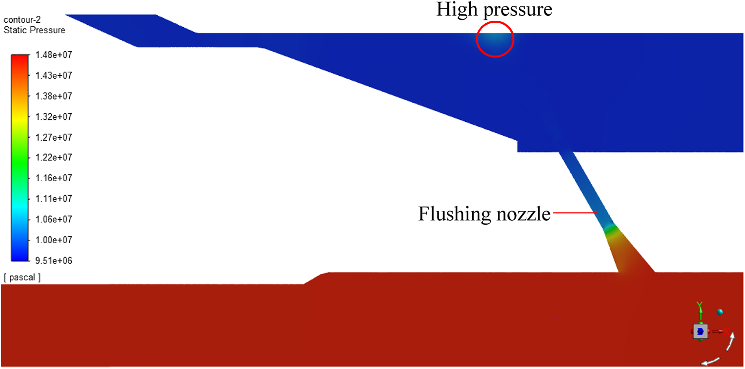
Figure 6: Static pressure contour of the flow field near the creamer nozzle
Fig. 7 shows the velocity distribution of the axial cross-section at the flushing nozzle and the circumferential cross-section at the blades. When the drilling fluid flows through the flushing nozzle, the jet velocity accelerates rapidly, reaching 96 m/s, which plays a key role in washing the rock cuttings (as shown in Fig. 7a). At the same time, the velocity of the drilling fluid flowing through the middle of the front and rear blades is the highest in the annulus flow (as shown in Fig. 7b). The flow in the middle of the blades has the effect of cooling the reaming tool. Therefore, the flushing efficiency of the reaming tool can be improved by optimizing the nozzle structure to increase the maximum flow rate through the middle of the blades.
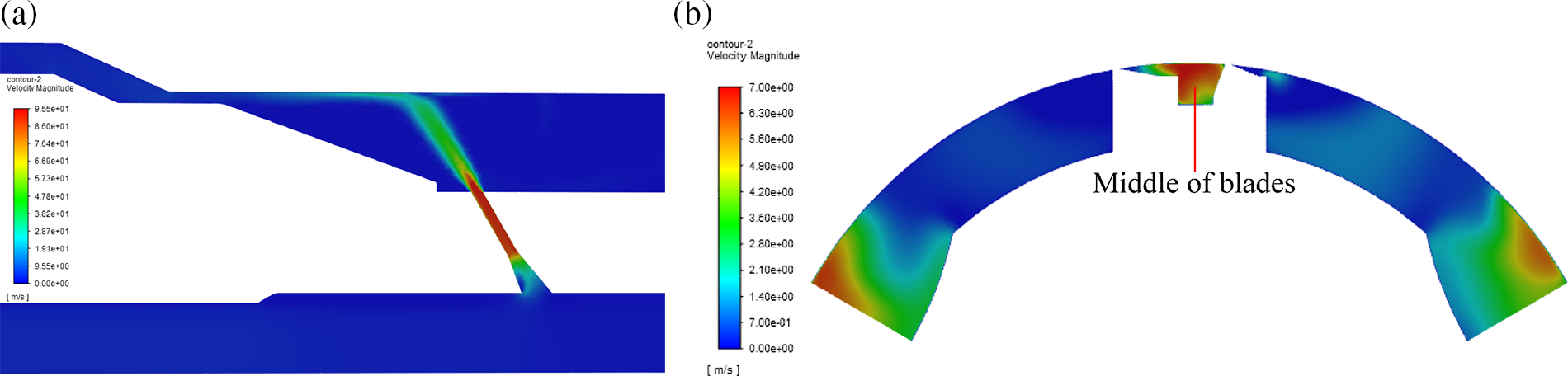
Figure 7: Flow field velocity contour (a) axial cross-section at the flushing nozzle, (b) circumferential cross-section at the blades
Fig. 8 shows the streamline contours of the drilling fluid through the flushing nozzle and the annulus between the reaming tool and the wellbore. When the drilling fluid flows out of the flushing nozzle, it impacts the wellbore and scatters into multiple jets. In addition, only a small portion of the drilling fluid flows through the middle of the blades. Therefore, the jet of the flushing nozzle is more effective in cleaning the rear blade than the front blade.
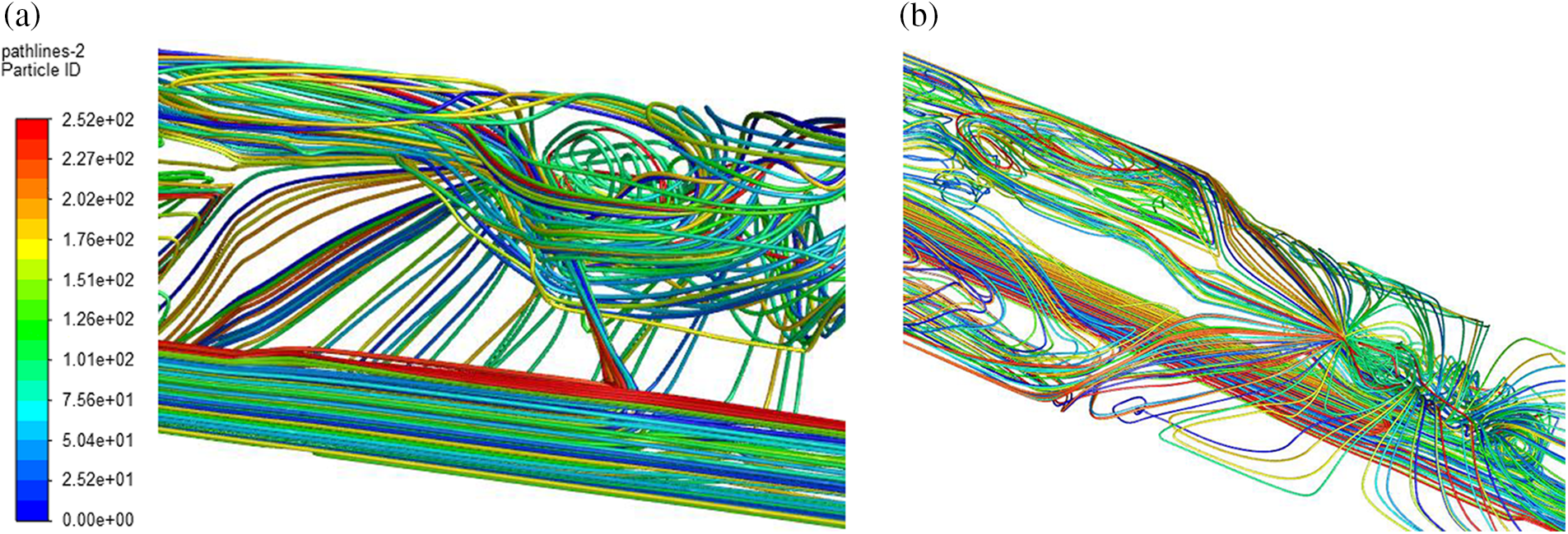
Figure 8: Streamline contours of the drilling fluid flow: (a) flushing nozzle, (b) annulus between creaming tool and wellbore
3.2 Effect of Flushing Nozzle Structure
The jet performance of the flushing nozzles of blades plays a vital role in washing the rock cuttings during the reaming operation. In particular, the diameter of the flushing nozzle directly affects the flow distribution of the drilling fluid, thus affecting the cleaning efficiency of the rack cuttings at the bottom hole and the reaming section. In this paper, the influence of nozzle structure on cleaning efficiency is analyzed from the perspective of flux distribution ratio, jet velocity of nozzle, and flow field characteristics in the middle of blades, which provides a theoretical basis for the optimization of nozzle structure.
In this paper, two types of nozzles are applied to the reaming tool, and the jet performance of the two nozzles are compared under the same simulation conditions. Fig. 9 illustrates the geometric structure of the cylindrical-cylindrical nozzle and conical-cylindrical nozzle.
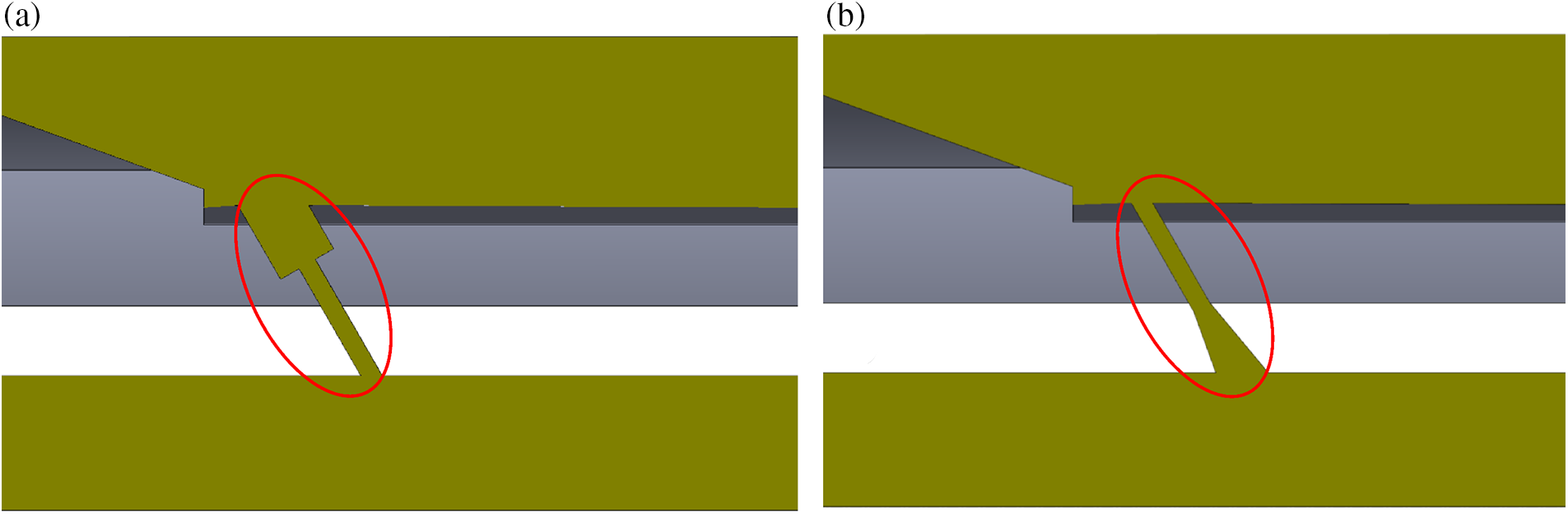
Figure 9: Geometric structure of nozzles: (a) cylindrical-cylindrical nozzle, (b) conical-cylindrical nozzle
In the numerical simulation, keeping the hydraulic diameter of the drilling bit as 20 mm, the diameter of the flushing nozzle as 6 mm, and the angle between the nozzle axis and the reaming tool axis as 60° unchanged, only the type of the nozzle is changed. The variation rule of flow distribution ratio with nozzle types is obtained, as shown in Fig. 10. It is obvious that the cylindrical-cylindrical nozzle corresponds to a higher flow ratio of drill bit, which means the conical-cylindrical nozzle has a better cleaning effect for the reaming operation. Besides, the flux of drilling fluid has no effect on the flow ratio of the drill bit.
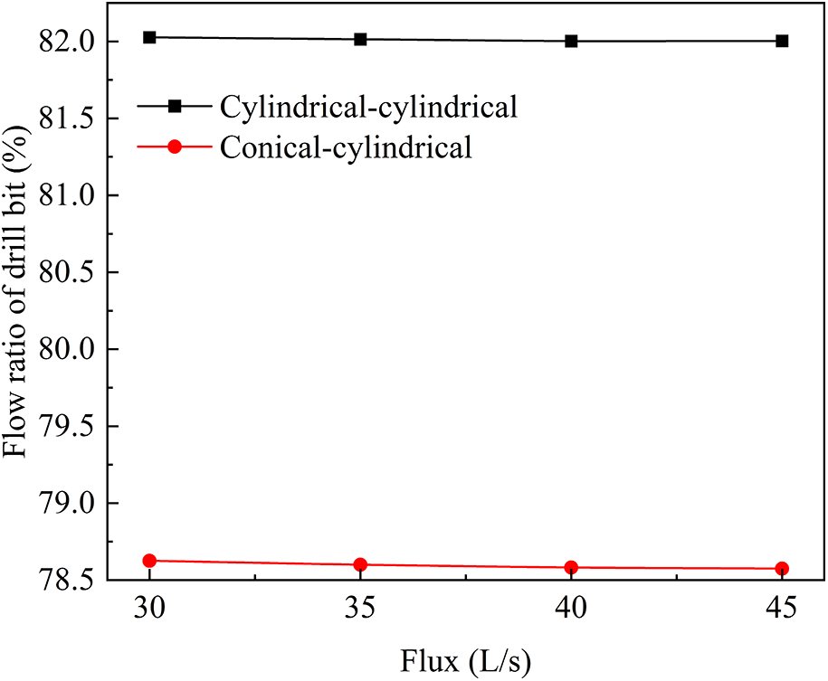
Figure 10: Effect of nozzle type on the flow rate of drill bit under different fluxes
Fig. 11 shows the effect of nozzle type on the maximum jet velocity under different fluxes. The flux of drill fluid has a significant effect on the maximum jet velocity. As the flux gradually increases, the maximum velocity of both nozzles gradually increases, and their magnitudes are positively proportional. At the same time, the maximum velocity of the conical-cylindrical nozzle is significantly larger than that of the cylindrical-cylindrical nozzle. The greater the jet velocity of the flushing nozzle, the greater the impact on the wellbore. Therefore, the reaming tool with a conical-cylindrical nozzle can obtain better cleaning efficiency.
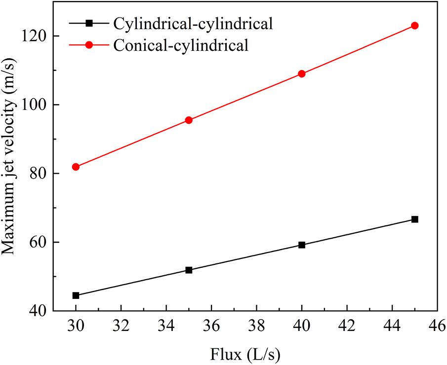
Figure 11: Effect of nozzle type on the maximum jet velocity under different fluxes
Fig. 12 shows the effect of nozzle type on the flux through blades (middle of blades) under different fluxes. As the flux of drilling fluid increases, the flux through the middle of blades increases linearly. Besides, the flux through blades corresponding to the conical-cylindrical nozzle is significantly larger than that of the cylindrical-cylindrical nozzle. The fluid flow through the middle of the blades mainly plays a role in flushing and cooling the blades of the reaming tool. According to the numerical simulation results, the conical-cylindrical nozzle has better cleaning and cooling effect under the same working conditions.
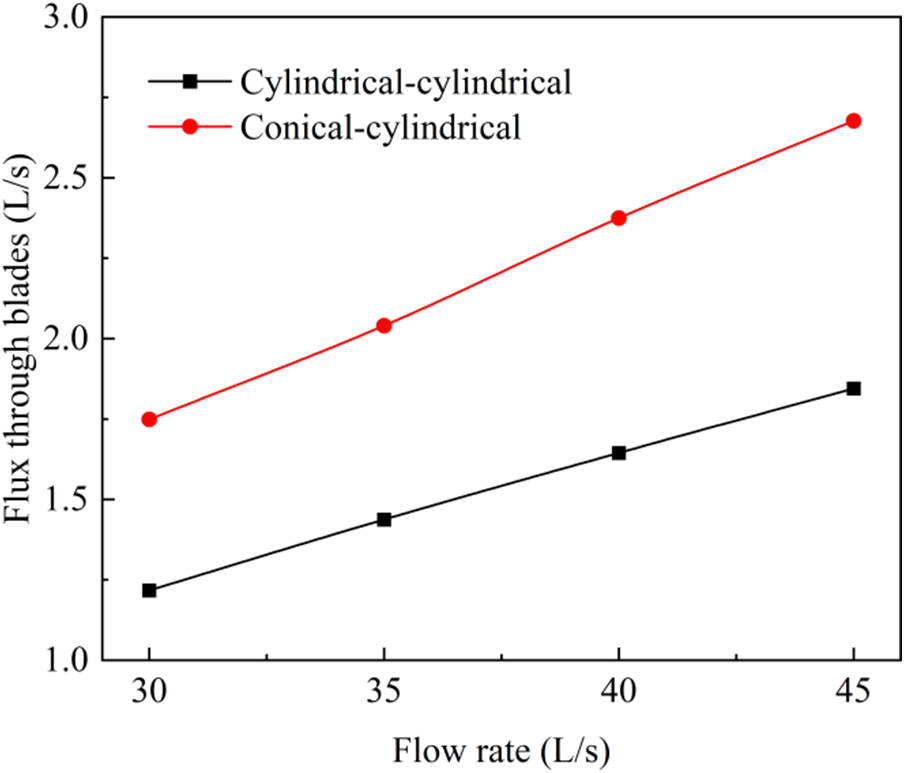
Figure 12: Effect of nozzle type on the flux through the middle of blades under different fluxes
3.2.2 Flushing Nozzle Diameter
In this section, the conical-cylindrical nozzle with a better cleaning effect is selected as the research object in the numerical simulation, keeping the hydraulic diameter of the drilling bit as 20 mm and only changing the diameter of the nozzle. Fig. 13 shows the flow rate of drill bit variation with nozzle diameter under different fluxes. The nozzle diameter has a significant effect on the flow distribution of the drill bit and reaming actuator. When only the flux of drilling fluid is changed, there is no change in the flow ratio of the drill bit. Moreover, the smaller the diameter of the flushing nozzle, the more drilling fluid is distributed to the drill, which is unfavorable for washing the rock cutting of the reaming operation.
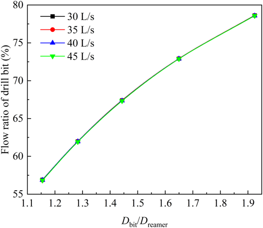
Figure 13: Effect of nozzle diameter on the flow rate of drill bit under different fluxes
Fig. 14 shows the effect of nozzle diameter on the maximum jet velocity under different fluxes. The larger the nozzle diameter, the greater the flux through the nozzle, but the lower the corresponding maximum jet velocity. Therefore, the rock-breaking efficiency of the reaming tool can be improved by reducing the flushing nozzle diameter.
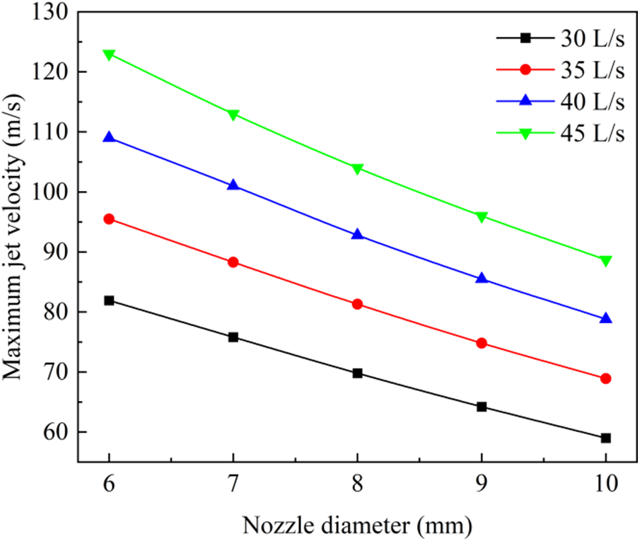
Figure 14: Effect of nozzle diameter on the maximum jet velocity under different fluxes
The flushing nozzle diameter also affects the flow field characteristics in the reaming blades. The effect of nozzle diameter on the flux through the middle of the blades under different flux is revealed in Fig. 15. As the nozzle diameter increases, the flux through the middle of the blades tends to increase slowly. The reason is that the larger the nozzle diameter, the larger the flow ratio obtained by the flushing nozzle, and thus more fluid flows through the middle of the blades.
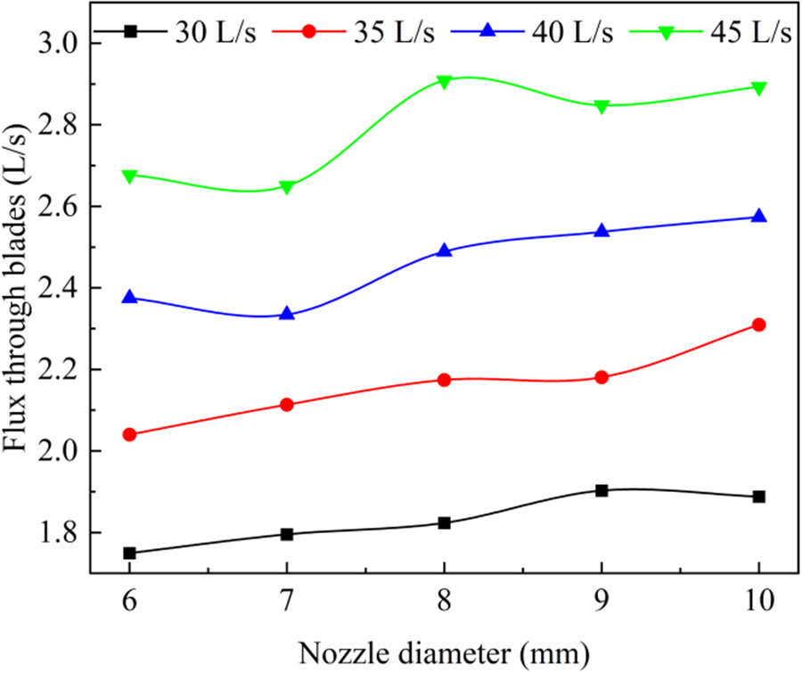
Figure 15: Effect of nozzle diameter on the flux through the middle of blades under different flux
Combining these results, it is obvious that reducing the nozzle diameter can increase the rock-breaking efficiency of the nozzle jet but would reduce the cutting cleaning efficiency of the nozzle jet. Therefore, there is an optimal nozzle diameter to make the reaming tool achieve the best reaming efficiency. According to the numerical simulation results, a nozzle diameter of 7 mm is initially optimized.
This paper proposes a new selective reaming tool while drilling and establishes a numerical simulation method applicable to the calculation of the internal and external flow field characteristics of the reaming tool. The turbulent flow of the three-dimensional full-size reaming tool is calculated by the RNG k-ε turbulence model. The effects of flushing nozzle type and flushing nozzle diameter on the flux distraction and velocity distribution of blades are systematically analyzed. The conclusions of the study are as follows:
(1) The structure of the selective reaming tool while drilling is well designed, and the jet of the flushing nozzle can play the role of cleaning rock cuttings and cooling the blades.
(2) The jet of the flushing nozzle is more effective in cleaning the rear blade than the front blade.
(3) Compared to the cylindrical-cylindrical nozzle, the conical-cylindrical nozzle can obtain better cleaning efficiency in the borehole reaming operation.
(4) There is an optimal nozzle diameter to make the reaming tool achieve the best reaming efficiency, and a nozzle diameter of 7 mm is initially optimized.
Funding Statement: The authors gratefully acknowledge the financial support by the Marine Economy Development Foundation of Guangdong Province (Grant No. GDNRC[2022]44).
Conflicts of Interest: The authors declare that they have no conflicts of interest to report regarding the present study.
References
1. Csonka, G., Tweedy, M. W., Cornel, S., Anderson, M. (1996). Ream while drilling technology applied successfully offshore Australia. SPE Asia Pacific Oil and Gas Conference, Adelaide, Australia, OnePetro. [Google Scholar]
2. Roohi, A., Ashena, R., Thonhauser, G., Finkbeiner, T., Gerbaud, L. et al. (2022). An experimental investigation of drilling performance improvement using reaming while drilling. Journal of Energy Resources Technology, 144(1), 013202. [Google Scholar]
3. Feng, Z. J., Liu, D. P., Zhou, Y. (2010). Analysis and countermeasure of shrinkage sticking in mud shale and salt-gypsum layer in East Sichuan. Drilling & Production Technology, 33(5), 123–125. [Google Scholar]
4. Zhou, W., Yu, Y., Liu, X. M. (2013). Research on rational reaming size in small-gap cementing. China Petroleum Machinery, 41(6), 28–30. [Google Scholar]
5. Kelley, S., Swadi, M., Charles, C. (2000). Ream while drilling technology solves difficult south texas drilling problem. IADC/SPE Drilling Conference, New Orleans, Louisiana, OnePetro. [Google Scholar]
6. Ashena, R., Elmgerbi, A., Rasouli, V. (2020). Severe wellbore instability in a complex lithology formation necessitating casing while drilling and continuous circulation system. Journal of Petroleum Exploration and Production Technology, 10, 1511–1532. [Google Scholar]
7. Huang, T., He, S. M., Tang, M., Ma, R. C. (2021). Analysis of the research status of downhole reaming tools. Oil Field Equipment, 50(3), 8–16. [Google Scholar]
8. Moellendick, E. (2008). Casing drilling improves mature field production, eliminates fluid losses, directionally drills wells. Drilling Contractor, 4, 76–79. [Google Scholar]
9. Zhang, K., Li, M., Liu, X. L. (2015). Advances of slim-hole cementing technologies at home and abroad. Drilling & Production Technology, 38(2), 23–26+7. [Google Scholar]
10. Hauer, T., Haydn, M., Abele, E. (2012). Influence of a diagonal pre-drilled hole on hole quality during the reaming process using multiblade tools. Journal of the Brazilian Society of Mechanical Sciences and Engineering, 34, 569–573. [Google Scholar]
11. Zhu, X., Yi, Q. (2018). Research and application of reaming subsidence control in horizontal directional drilling. Tunnelling and Underground Space Technology, 75, 1–10. [Google Scholar]
12. Deng, X. W., Wang, L. (2018). Discussion on optimization of directional reaming while drilling process in ultra-deep well. Technology Supervision in Petroleum Industry, 34(3), 30–33. [Google Scholar]
13. Dong, S., Zeng, C., Ariaratnam, S. T., Ma, B., Yan, X. et al. (2020). Experimental and performance analysis of reverse circulation reaming in horizontal directional drilling. Tunnelling and Underground Space Technology, 95, 103128. [Google Scholar]
14. Fujimoto, T., Okada, A., Okamoto, Y. (2012). Optimization of nozzle flushing method for smooth debris exclusion in wire EDM. Key Engineering Materials, 516, 73–78. [Google Scholar]
15. Dechiffre, L., Belluco, W., Zeng, Z. (2001). An investigation of reaming test parameters used for cutting fluid evaluations. Tribology & Lubrication Technology, 57(7), 24–28. [Google Scholar]
16. Towfighian, S., Behdinan, K., Papini, M. (2008). Finite element modelling of low-speed femur reaming using reamers with irregular tooth spacing. Journal of Sound and Vibration, 318(4–5), 868–883. [Google Scholar]
17. Shi, J. W., Ge, S., Sheng, X. Z. (2022). Numerical investigation on the aerodynamic noise generated by a simplified double-strip pantograph. Fluid Dynamics & Materials Processing, 18(2), 463–480. https://doi.org/10.32604/fdmp.2022.017508 [Google Scholar] [CrossRef]
18. Wilcox, D. (2001). Turbulence modeling–An overview. 39th Aerospace Sciences Meeting and Exhibit, pp. 724. Nevada, USA. [Google Scholar]
19. Duraisamy, K., Iaccarino, G., Xiao, H. (2019). Turbulence modeling in the age of data. Annual Review of Fluid Mechanics, 51, 357–377. [Google Scholar]
20. Chen, Y. C., Guo, Z. H., Lei, Y. Y. (2012). Simulation of flow field in the abrasive water jet nozzle. Chinese Hydraulics & Pneumatics, 10, 66–68. [Google Scholar]
21. Katz, A., Sankaran, V. (2011). Mesh quality effects on the accuracy of CFD solutions on unstructured meshes. Journal of Computational Physics, 230(20), 7670–7686. [Google Scholar]
22. Koeltzsch, K., Dinkelacker, A., Grundmann, R. (2002). Flow over convergent and divergent wall riblets. Experiments in Fluids, 33(2), 346–350. [Google Scholar]
Cite This Article
 Copyright © 2023 The Author(s). Published by Tech Science Press.
This work is licensed under a Creative Commons Attribution 4.0 International License , which permits unrestricted use, distribution, and reproduction in any medium, provided the original work is properly cited.
 Downloads
 Citation Tools