
 Submit a Paper
 Propose a Special lssue
 Open Access
ARTICLE
Integrity and Failure Analysis of Cement Sheath Subjected to Coalbed Methane Fracturing
1 Key Laboratory of Unconventional Natural Gas Evaluation and Development in Complex Tectonic Areas, Ministry of Natural Resources, Guiyang, 550081, China
2 Guizhou Engineering Research Institute of Oil & Gas Exploration and Development, Guiyang, 550081, China
3 School of Petroleum Engineering, China University of Petroleum (East China), Qingdao, 266580, China
4 Shandong Key Laboratory of Oilfield Chemistry, Key Laboratory of Unconventional Oil & Gas Development, China University of Petroleum (East China), Qingdao, 266580, China
* Corresponding Authors: Heng Yang. Email: ; Yuanlong Wei. Email:
Fluid Dynamics & Materials Processing 2023, 19(2), 329-344. https://doi.org/10.32604/fdmp.2022.020216
Received 11 November 2021; Accepted 28 February 2022; Issue published 29 August 2022
 View Full Text
 Download PDF
Abstract
Perforation and fracturing are typically associated with the development of coalbed methane wells. As the cement sheath is prone to failure during this process, in this work, the effects of the casing pressure, elastic modulus of the cement, elastic modulus of the formation, and casing eccentricity on the resulting stresses are analyzed in the frame of a finite element method. Subsequently, sensitivity response curves of the cement sheath stress are plotted by normalizing all factors. The results show that the maximum circumferential stress and Mises stress of the cement sheath increase with the casing internal pressure, elastic modulus of the cement and casing eccentricity. As the elastic modulus of the formation increases, the maximum circumferential stress of the cement sheath decreases, and its maximum Mises stress increases slightly. The cement sheath undergoes tensile failure during coalbed methane fracturing. The stress sensitivity of the cement sheath to the influential parameters is in the following order: casing internal pressure > elastic modulus of cement sheath > casing eccentricity > elastic modulus of formation.Graphic Abstract
Keywords
Nomenclature
| | casing eccentricity rate |
| Δl | casing eccentricity distance, mm |
| rb | borehole radius, mm |
| rc | outer radius of casing, mm |
| Abbreviations | |
| CCFC | casing-cement sheath-formation combination |
| CIP | casing internal pressure |
| CS | circumferential stress |
| MS | Mises stress |
| EM | elastic modulus |
Coal fields are characterized by a high gas content, high in-situ stress, low permeability, and low reservoir pressure. Therefore, hydraulic fracturing is typically used to extract coalbed methane [1]. Coalbed methane wells are primarily developed in a layered fracture-layer drainage mode. Layered perforation and fracturing are performed on the main coalbed during reservoir reconstruction. The casing internal pressure (CIP) fluctuates significantly during the fracturing process, which is likely to jeopardize the integrity of the wellbore cement sheath. Integrity failure affects the fracturing and annulus sealing effects, posing a significant threat to the environment, health, and economy [2].
The researchers [3–5] proved through laboratory experiments that the integrity of the cement sheath will fail under varying CIP. Gray et al. [6] used a staged finite element approach to study the near-wellbore zone stress changes during all stages of life of well, analyzing the possibility of cement sheath integrity failure. Zhang [1] analyzed the failure of cement sheath integrity during the hydraulic fracturing of coalbed methane through indoor experiments and finite element simulations. The results showed that during the hydraulic fracturing of coalbed methane, the cement sheath was prone to tensile and shear failure near the perforations; however, beyond a distance of one hole, the possibility of cement sheath integrity failure reduced significantly. Tian et al. [7] reported that during the volumetric fracturing of shale gas horizontal wells, the shrinkage effect of the annulus high-pressure bound fluid caused by a significant decrease in temperature and the coupling of other factors contributed primarily to casing damage. Liu et al. [8,9] used an analytical solution of the casing-cement sheath-formation combination (CCFC) stress distribution and found that a smaller casing inner diameter and elastic modulus (EM) of the cement sheath resulted in a safer cement sheath. Radial local loads were more likely to cause casing failures than parallel loads, and the inner surface of the cement sheath of the intermediate casing was more prone to tensile failure. Dai [10] analyzed the effect of the casing eccentricity on cement sheath integrity failure and indicated that the cement sheath was susceptible to tensile fracture at a weak point. It was found that the greater the eccentricity, the smaller was the critical pressure at which the cement sheath began to undergo plasticity and complete plasticity. Li et al. [11] investigated interfacial crack propagation in a cement sheath under shale gas volume fracturing conditions; they found that increasing the EM of the cement sheath and appropriately reducing the wellhead pressure and fracturing time reduced the interfacial crack propagation length. Zeng et al. [12] and Xi et al. [13] evaluated the integrity of the cement sheath during volume fracturing under the coupled effect of temperature and pressure. They reported that a reasonable control of the injection temperature and fracturing displacement, reducing the EM of the cement sheath, and increasing the Poisson’s ratio of the cement sheath can effectively prevent tensile failure in cement sheaths. Fan et al. [14] proposed an analysis method that can simulate the stress distribution of a wellbore during drilling, cementing, and fracturing based on a step-by-step finite element simulation. Restrepo et al. [15] investigated the effects of the cement sheath missing angle, casing eccentricity, and fluid pressure at a missing cement sheath on wellbore integrity. They reported that the lack of a cement sheath caused by residual drilling fluid in the annulus caused failure. Li et al. [16] conducted a study pertaining to the wellbore integrity failure of shale gas fracturing and reported the form of and reasons for wellbore integrity failure. Wang et al. [17] analyzed wellbore integrity during the fracturing process of shale gas horizontal wells and reported that increasing the casing wall thickness and Poisson’s ratio of the cement sheath, reducing the EM of the cement sheath, and selecting an appropriate cement sheath thickness can ensure the integrity of the wellbore. Patel et al. [18–20] investigated the effects of the load, material properties, and cement sheath size on the cement sheath integrity of a liner-casing overlapping section of offshore oil and gas wells. A sensitivity response curve was constructed to evaluate the effects of different operating and design parameters on the stress of the cement sheath.
Existing studies have primarily focused on the effects of shale gas fracturing on wellbore integrity, whereas only a few studies have highlighted the integrity of cement sheaths during coalbed methane fracturing. Compared to shale formations, coal formations have a lower strength and elastic modulus, a higher porosity and permeability, and a lower casing pressure during fracturing. Because the physical properties of coal and shale formations are different, the integrity of the cement sheath during coalbed methane fracturing must be investigated. Studies pertaining to the effects of various factors on the integrity failure of cement sheath are abundant, whereas studies regarding the response of each factor to the stress sensitivity of cement sheaths are scarce. In this study, based on finite element models of the CCFC, the effects of the CIP, EM of the cement sheath, EM of formation, and casing eccentricity on cement sheath integrity were investigated. A sensitivity response curve was constructed to analyze the sensitivity of each factor to the stress of the cement sheath during coalbed methane fracturing. Measures for preventing cement sheath integrity failure during coalbed methane well fracturing are presented herein, which can serve as a reference for the safe development of coalbed methane wells.
2 Finite Element Model of Casing-Cement Sheath-Formation Combination
The following assumptions are made regarding the model used in this study:
(1) The model is a plane-strain model [21–24].
(2) The model material is isotropic and homogeneous.
(3) The casing–cement sheath and formation–cement sheath interfaces are in close contact with no gap between them.
Using a coalbed methane well as an example, the integrity failure of the cement sheath of the caprock during coalbed methane fracturing was investigated. This well was composed of three coalbeds. The finite element models of the CCFC at the caprock position of the three coalbeds were used to evaluate the failure mechanism of the cement sheath at the caprock of different coalbed depths under fracturing conditions. The locations of the models are shown in Fig. 1. The model parameters are shown in Table 1. Using model A as an example, the finite element model of the CCFC is shown in Fig. 2. To improve the calculation accuracy, the meshing of the near-well formation was intensified gradually with decreasing distance to the wellbore. The green region in the innermost layer of the model represents the casing, the yellow region in the middle layer represents the cement sheath, and the red region in the outermost layer represents the formation. The boundary conditions of the model are symmetrical constraints imposed on the left and lower ends of the model. The model load is the ground stress applied to the upper and right ends of the formation, the CIP applied to the inner wall of the casing, and the pressure of the liquid column applied to the outer wall of the casing and the inner wall of the formation. When the well fractured, the CIP was 50 MPa. The density of the overlying sediment was 1.8–2.2 g/cm3, the average overlying rock pressure was approximately 20 MPa/km, and the uniform in situ stresses of models A, B, and C were 11.2, 12.8, and 17 MPa, respectively. The density of the drilling fluid was 1.03 g/cm3, the density of the cementing slurry was 1.85 g/cm3, the cement slurry return height was 517.6 m, and the liquid column pressures of models A, B, and C during cementing were 6.11, 7.6, and 11.48 MPa, respectively. The simulation was performed in two steps. In the first step, an in situ stress analysis was performed to balance the in situ stress; in the second step, a static analysis was performed to simulate the changes in the CIP. The compressive strength of the cement sheath was 34.82 MPa, whereas the tensile strength was 3.86 MPa.
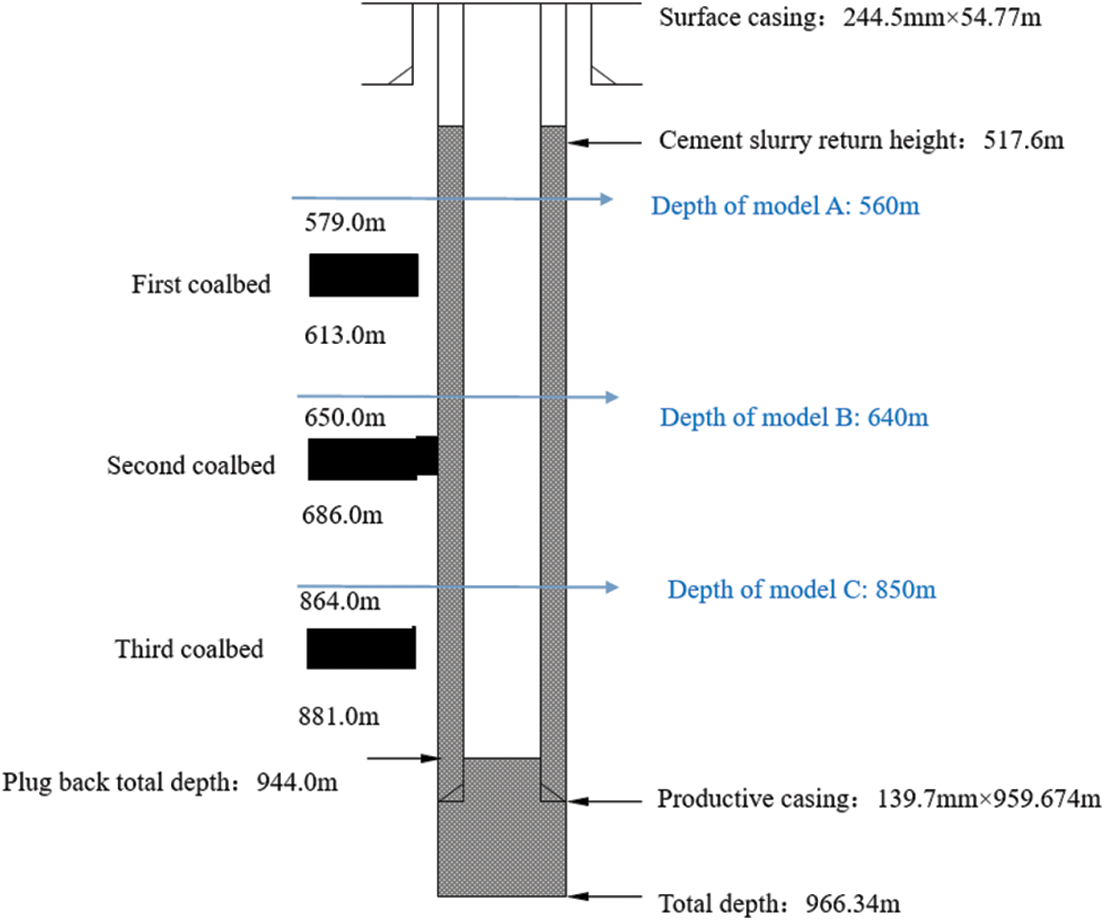
Figure 1: Location of finite element models
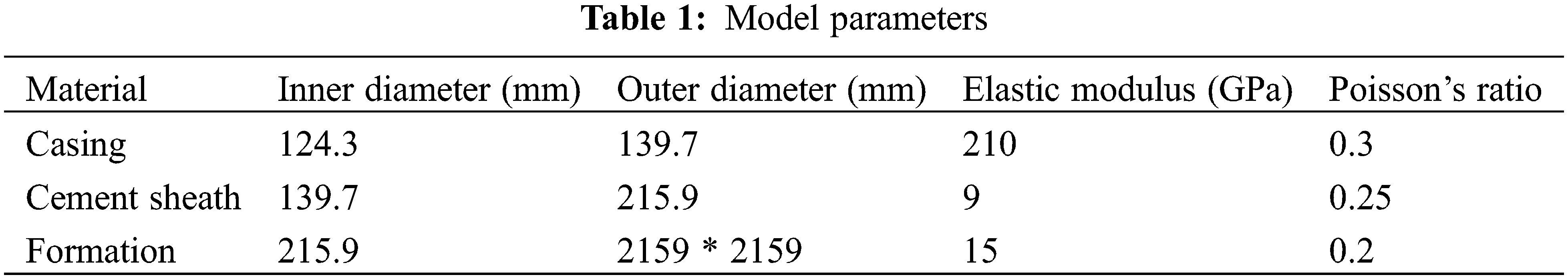
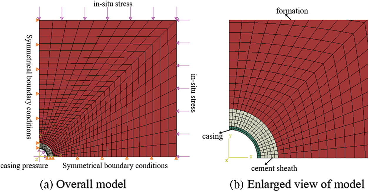
Figure 2: Finite element model of CCFC
Take the formation in model C, the liquid column pressure is 1 to 50 MPa, and the in-situ stress is 17 MPa. The analytical and finite element solutions of the radial stress and circumferential stress at the wellbore are shown in Fig. 3. The maximum difference between the finite element solution and the analytical solution is 3.7 MPa, and the minimum difference is 0MPa. The analytical solution is similar to the finite element solution, which verifies the validity of the finite element model. The liquid column pressure is 50 MPa, the in-situ stress is 17 MPa, and the radial stress and circumferential stress at the wellbore with different mesh numbers are shown in Fig. 4. The radial stress and circumferential stress of the formation with different mesh numbers are very close, which verifies the mesh.
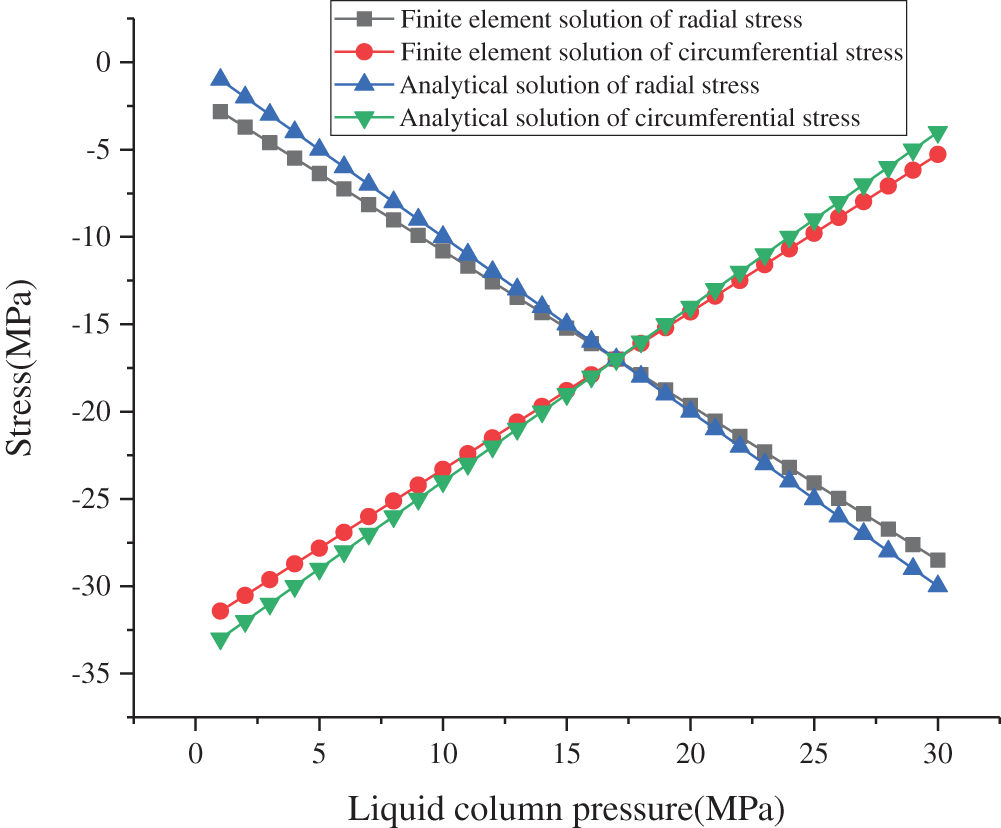
Figure 3: Comparison of finite element solution and analytical solution
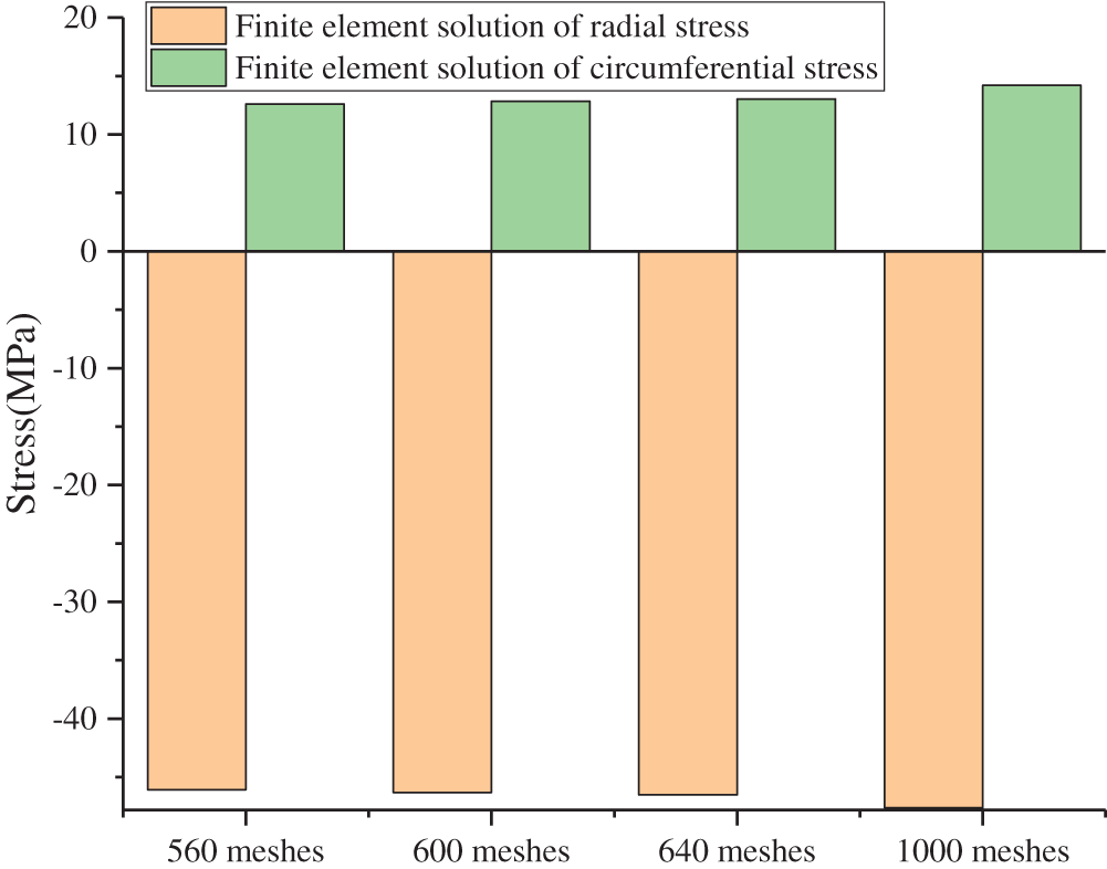
Figure 4: Cement sheath stress with different mesh numbers
3 Integrity of Cement Sheath under Different Conditions
The fourth strength criterion is used to assess the yield failure of the cement sheath [25,26]. When the maximum Mises stress (MS) of the cement sheath exceeds its compressive strength, the cement sheath will fail. Meanwhile, the maximum tensile stress criterion is used to determine the tensile failure of the cement sheath [27–30]. When the maximum circumferential tensile stress of the cement sheath exceeds its tensile strength, the cement sheath fails under tension. Therefore, the circumferential stress (CS) and MS of the cement sheath are used as dependent variables to analyze the effect of each influencing factor on the integrity failure of the cement sheath. During the fracturing process of coalbed methane wells, CIP changes and formation property differences occur; hence, it is difficult to ensure that the casing is completely centered and that the EM of the cement sheath can be adjusted. Therefore, the effects of these factors on the integrity failure of the cement sheath were investigated.
The other parameters of the model remained unchanged, and the CIP was set as 0–50 MPa to determine the effect of the CIP on the integrity failure of the cement sheath. The CS and MS cloud diagrams of the cement sheath of model A at a CIP of 50 MPa are shown in Fig. 5. As shown in Fig. 5, the circumferential tensile stress and MS of the cement sheath decreased gradually from the inside to the outside and were the highest at the inner wall. Changes in the CS and MS on the inner wall of the cement sheath of different models with the CIP are shown in Figs. 6 and 7, respectively. As shown in these figures, the circumferential tensile stress and MS of the cement sheath increased with the CIP. Under the same CIP, the circumferential tensile stress of model A was the highest, whereas that of model C was the lowest. This implies that the shallower the cement sheath, the more likely is circumferential tensile failure. Under the same CIP, the MS of model A was the lowest, whereas that of model C was the highest. This implies that the deeper the cement sheath, the more susceptible it is to failure. When the CIP was 50 MPa, the maximum MS of the cement sheath of models A, B, and C was lower than the compressive strength of the cement sheath, and the cement sheath did not fail. When the CIP was 36 MPa, the maximum CS of the cement sheath of models A, B, and C exceeded the tensile strength of the cement sheath, and the cement sheath experienced tensile failure. To prevent integrity failure of the cement sheath, the CIP should be controlled within a reasonable range.
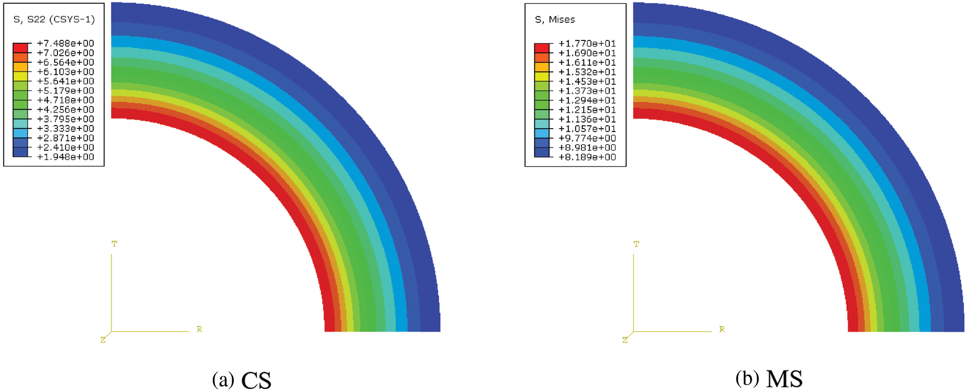
Figure 5: Cement sheath CS and MS cloud diagrams
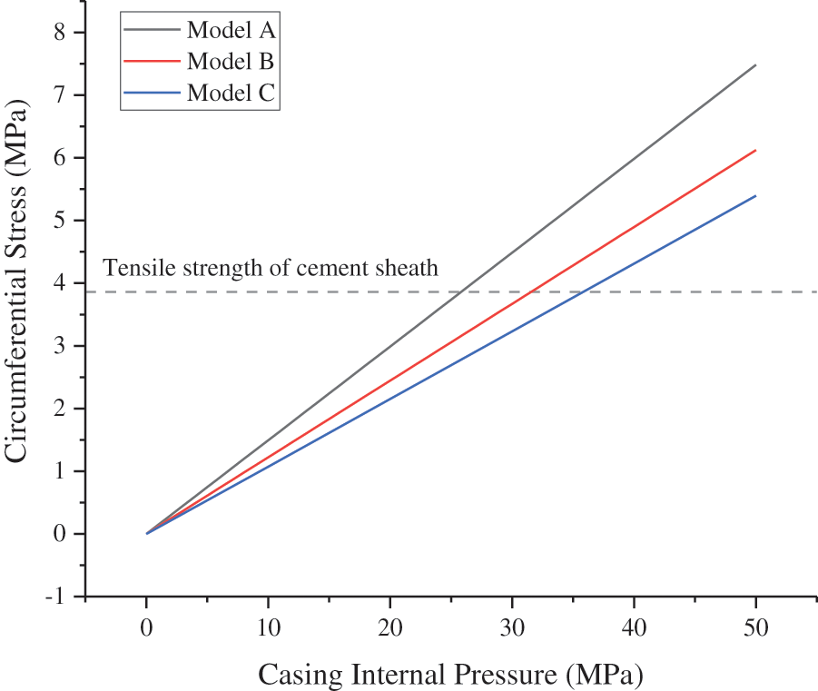
Figure 6: CS of cement sheath with varying CIP
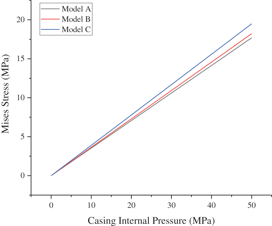
Figure 7: MS of cement sheath with varying CIP
3.2 Elastic Modulus of Cement Sheath
The other parameters of the model remained unchanged, whereas the EM of the cement sheath was set as 3–15 GPa, and the CIP was set as 50 MPa. The CS and MS at the inner wall of the cement sheath changed with the EM of the cement sheath, as shown in Figs. 8 and 9, respectively. As shown in the figures, the circumferential tensile stress and MS of the cement sheath increased with the EM of the cement sheath. The higher the EM of the cement sheath, the higher was the stress. Model A was the most susceptible to tensile failure. When the EM of the cement sheath was less than 6 GPa, the maximum circumferential tensile stress of the cement sheath of models A, B, and C was less than the tensile strength, and the cement sheath did not experience tensile failure. The maximum MS of the cement sheath of models A, B, and C was less than the compressive strength of the cement sheath, and the cement sheath did not fail. Reducing the EM of the cement sheath effectively reduced its stress and ensured its integrity.
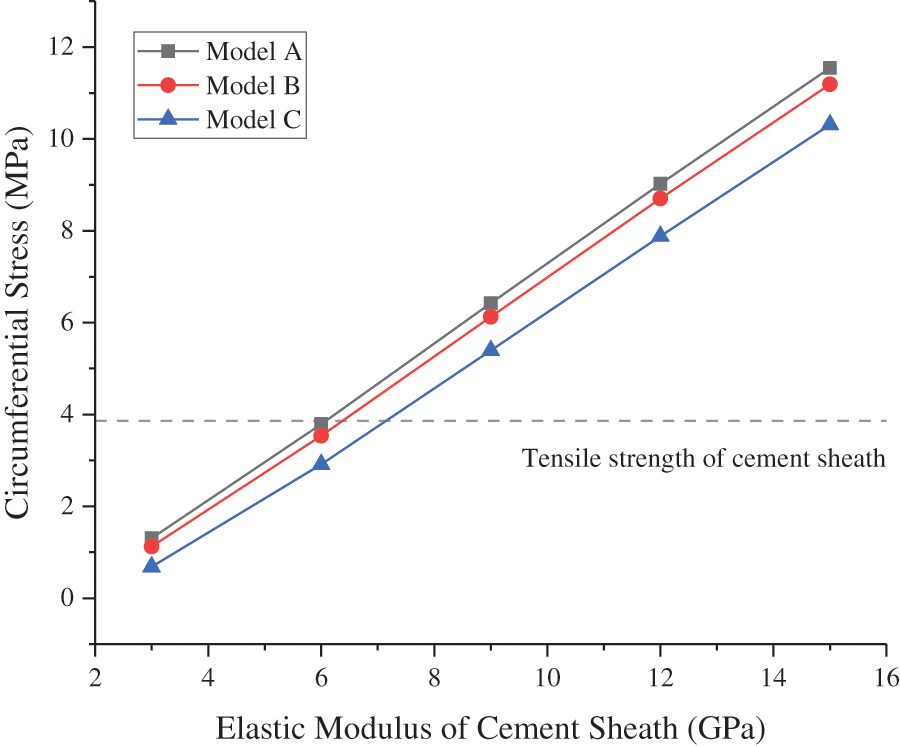
Figure 8: CS of cement sheath with varying EM
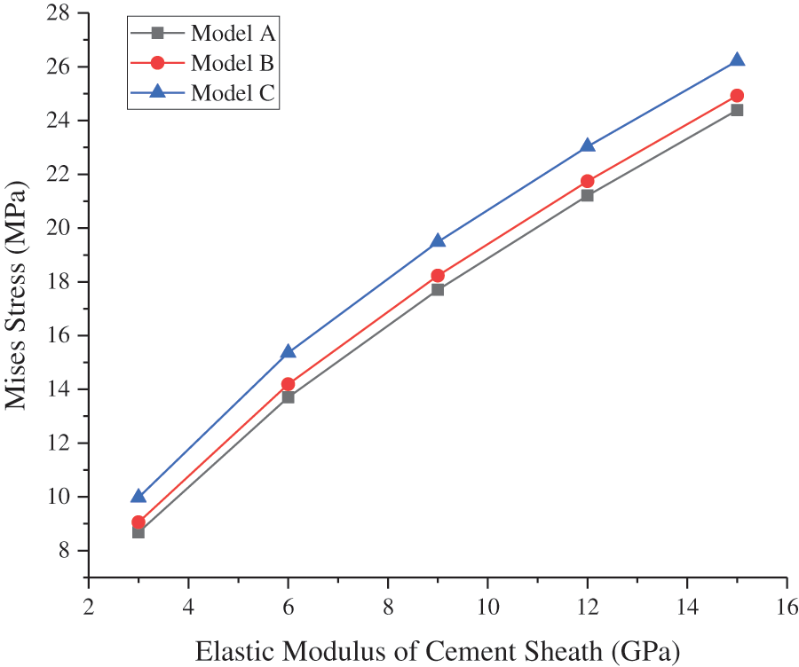
Figure 9: MS of cement sheath with varying EM
3.3 Elastic Modulus of Formation
The other parameters of the model remained unchanged, whereas the CIP was set to 50 MPa. The CS and MS at the inner wall of the cement sheath of different models varied with the EM of formation, as shown in Figs. 10 and 11, respectively. As shown in Fig. 10, the circumferential tensile stress of the cement sheath decreased as the EM of formation increased. The higher the EM of formation, the less susceptible it was to the tensile failure of the cement sheath. As shown in Fig. 11, the EM of formation did not significantly affect the MS of the cement sheath. In model C, the EM of formation increased from 5 to 25 GPa, and the maximum MS of the cement sheath increased from 18.85 to 19.86 MPa, which was only an increase of 1.01 MPa.
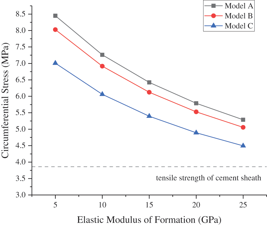
Figure 10: CS of cement sheath with varying EM of formation
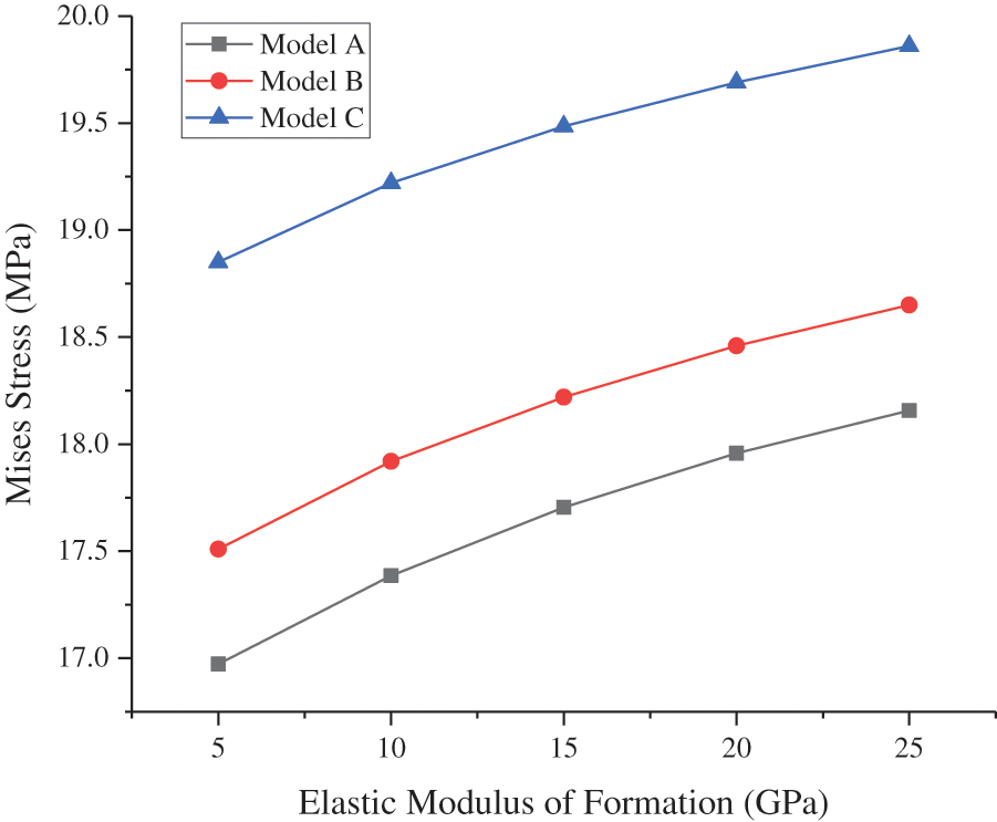
Figure 11: MS of cement sheath with varying EM of formation
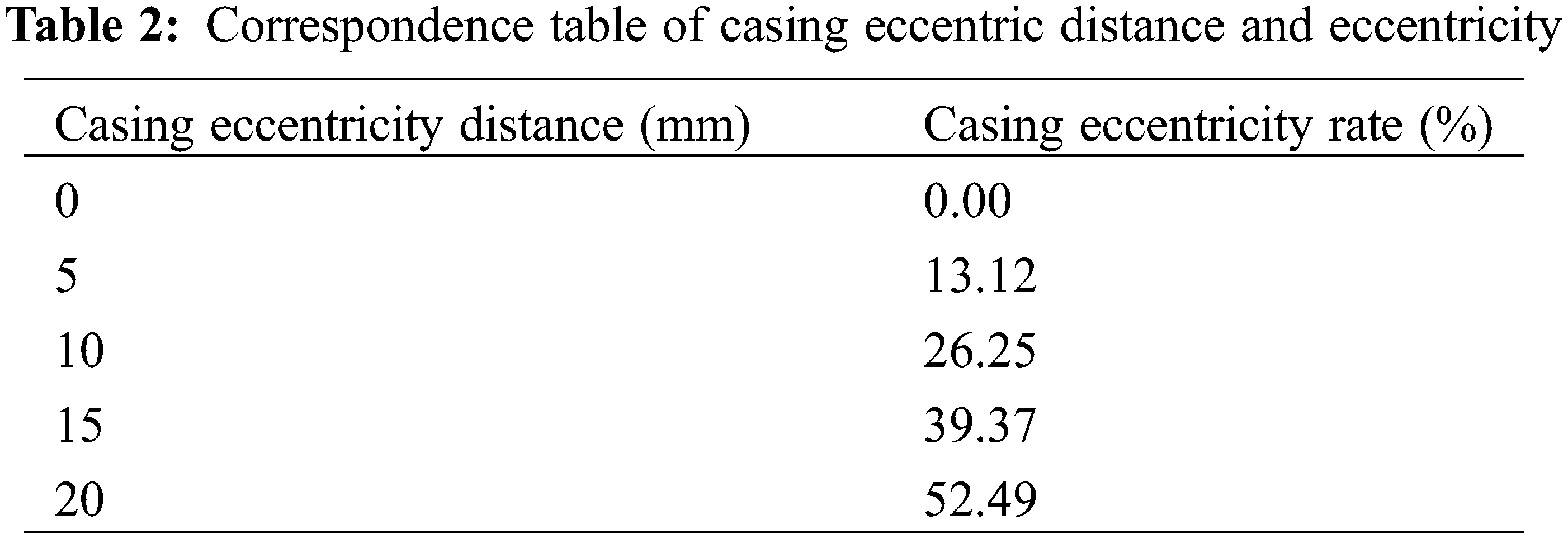
The other parameters of the model remained unchanged, whereas the CIP was set to 50 MPa. To determine the effect of casing eccentricity on the integrity failure of the cement sheath, the casing eccentricity was set to 0, 5, 10, 15, and 20 mm. The corresponding relationship between the casing eccentricity distance and eccentricity rate is shown in Table 2. The formula for calculating the casing eccentricity rate is shown in Eq. (1). Owing to the symmetry of the model, only one half of the overall model was analyzed. The casing eccentricity rate is defined as follows:
For different casing eccentricity rates, using model A as an example, the CS and MS cloud diagrams of the cement sheath in model A are as shown in Figs. 12 and 13, respectively. As shown in these figures, under different casing eccentricity rates, the CS and MS of the cement sheath decreased gradually from the inner wall to the outer wall. Meanwhile, under different casing eccentricity rates, the maximum CS and MS of the cement sheath were both located on the inner wall of the cement sheath, where the thickness was the smallest.
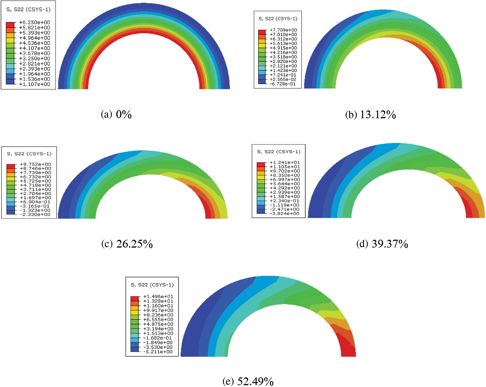
Figure 12: CS cloud diagram of cement sheath under different casing eccentricity rates
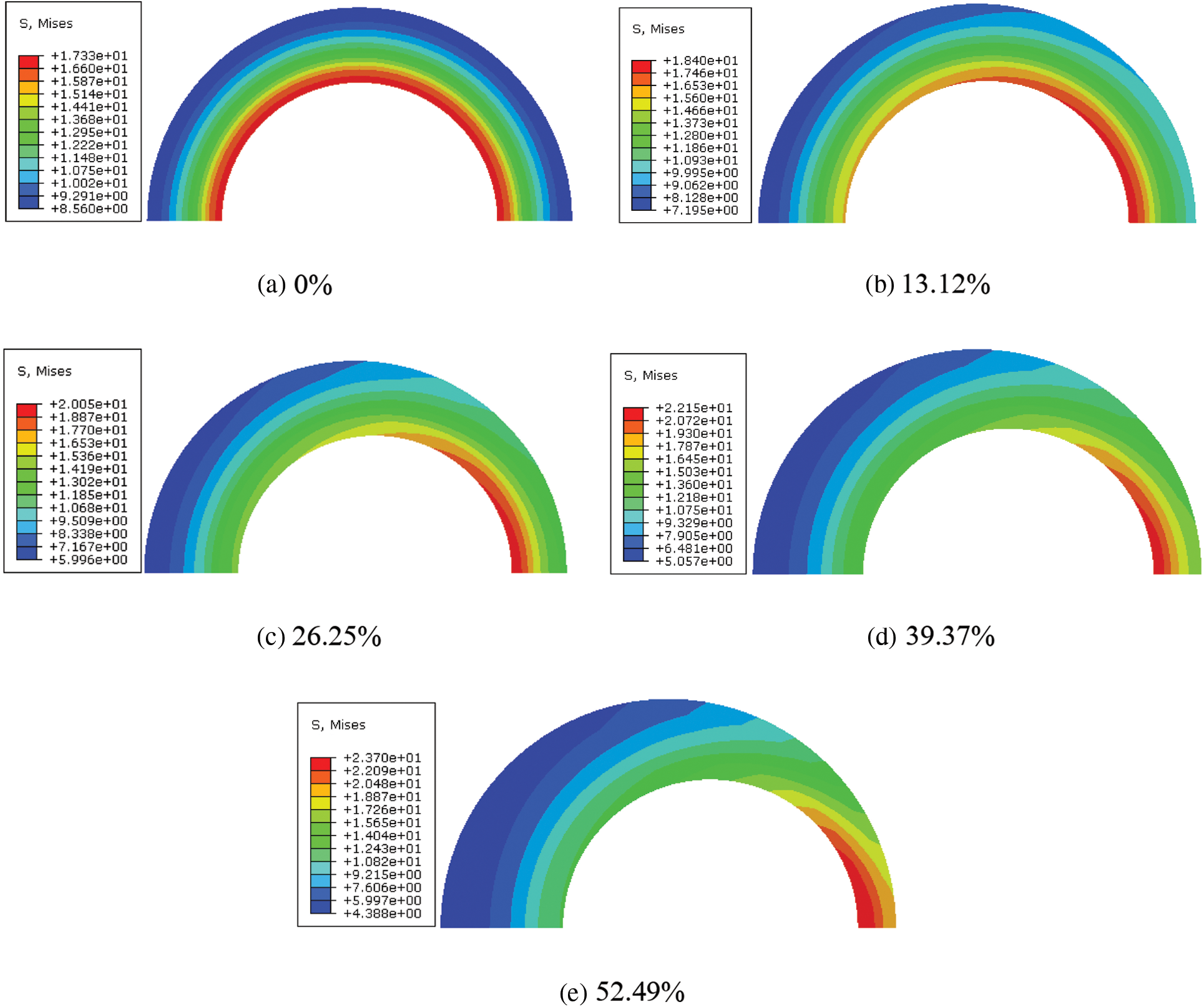
Figure 13: MS cloud diagram of cement sheath under different casing eccentricity rates
The angles of the thinnest and thickest sections of the cement sheath were 0° and 180°, respectively. The CS and MS under different casing eccentricity rates at different angles of the inner wall of the cement sheath in model A are shown in Figs. 14 and 15, respectively. As shown in these figures, the circumferential tensile stress and MS of the inner wall of the cement sheath under different casing eccentricity rates decreased as the angle increased. At a certain angle between 0° and 70°, the circumferential tensile stress and MS of the cement sheath increased with an increase in the casing eccentricity rate. At a certain angle between 70° and 180°, the circumferential tensile stress and MS of the cement sheath increased with a decrease in the casing eccentricity rate. As shown in Figs. 16 and 17, the maximum CS and MS of the cement sheath of the different models were consistent with the casing eccentricity rate. The greater the casing eccentricity rate, the greater were the maximum CS and MS values of the cement sheath. To reduce the stress of the cement sheath and ensure the integrity of the cement sheath, the casing should be positioned in the center.
Figure 14: CS on inner wall of cement sheath under different casing eccentricity rates
Figure 15: MS on inner wall of cement sheath under different casing eccentricity rates
Figure 16: Maximum CS of cement sheath of different models with different casing eccentricity rates
Figure 17: Maximum MS of the cement sheath of different models with different casing eccentricity rates
4 Sensitivity of Cement Sheath Integrity and Engineering Countermeasures
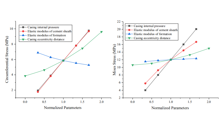
The sensitivity response curve can be used to indicate the degree of influence of different parameters on the dependent variable [18]. Specifically, this curve is constructed by changing the value of one variable and maintaining the base value of the other variables. Subsequently, the value of each variable is divided by its base value to obtain the normalized value [19,20]. Using model A as an example, we plotted the sensitivity response curves of various variables to the maximum CS and MS of the cement sheath and then evaluated the sensitivity of each variable to the stress of the cement sheath. The values of each parameter are listed in Table 3. As shown in Fig. 18, the CIP, EM of the cement sheath, and eccentricity of the casing were positively correlated with the maximum CS of the cement sheath. By contrast, the EM of formation was negatively correlated to the maximum CS of the cement sheath. The maximum CS sensitivity of the cement sheath was in the following order: CIP > EM of cement sheath > casing eccentricity > EM of formation. The CIP and EM of the cement sheath were similar to the maximum CS of the cement sheath in terms of sensitivity. As shown in Fig. 19, the CIP, EM of the cement sheath, EM of formation, and casing eccentricity were positively correlated to the maximum MS of the cement sheath. The maximum MS sensitivity of the cement sheath was in the following order: CIP > EM of cement sheath > casing eccentricity > EM of formation. To prevent integrity failure of the cement sheath, a reasonable CIP should be selected, the EM of the cement sheath should be reduced, and the casing should be well centered. As shown in Figs. 18 and 19, the CIP had the most significant effect on the integrity of the cement sheath, followed by the EM of the cement sheath. The effect of the casing eccentric distance on the integrity of the cement sheath was smaller than that of the EM of the cement sheath. Additionally, the EM of formation had the smallest effect. To ensure the integrity of the cement sheath, a reasonable CIP should be selected, a cement sheath with a low EM should be used, and the casing should be well centered.
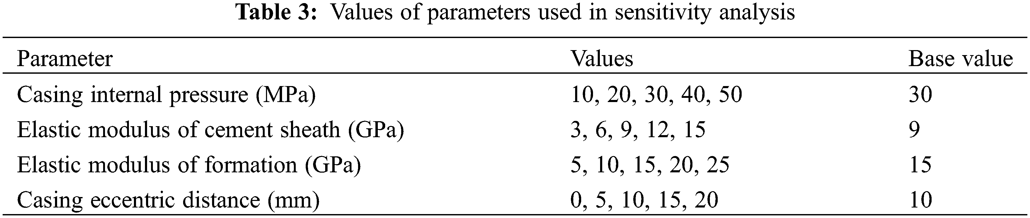
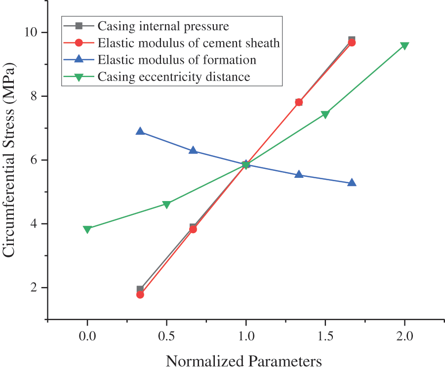
Figure 18: Sensitivity of CS in cement sheath to various parameters
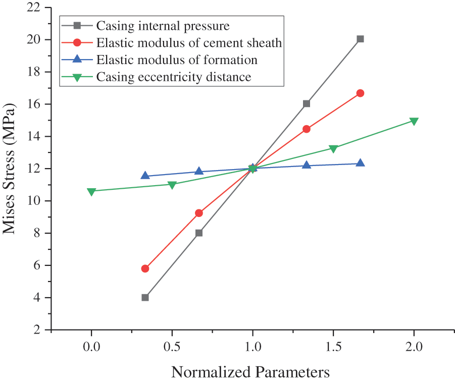
Figure 19: Sensitivity of MS in cement sheath to various parameters
(1) The CIP, EM of the cement sheath, and casing eccentricity were positively correlated with the maximum CS of the cement sheath. By contrast, the EM of formation was negatively correlated with the maximum CS of the cement sheath. The CIP, EM of the cement sheath, EM of formation, and casing eccentricity were positively correlated with the maximum MS of the cement sheath.
(2) Tensile failure occurred in the cement sheath during coalbed methane fracturing. Compared to the cement sheath of the third coalbed caprock, the cement sheath of the first coalbed caprock was more susceptible to tensile failure. Under the same conditions, the cement sheath of the third coalbed caprock had the highest MS, and the cement sheath was more susceptible to failure.
(3) The order of sensitivity of the cement sheath integrity was as follows: CIP > EM of cement sheath > casing eccentricity > EM of formation. To ensure the integrity of the cement sheath, a reasonable CIP should be selected, a cement sheath with a low EM should be used, and the casing should be well centered.
Funding Statement: This study was funded by the Provincial Geological Exploration Fund of Guizhou Province (208-9912-JBN-UTS0).
Conflicts of Interest: The authors declare that they have no conflicts of interest to report regarding the present study.
References
1. Zhang, Q. (2016). Study on failure of cement ring hydraulic fracturing under coalbed methane reservoir (Master Thesis). China University of Petroleum (Huadong). [Google Scholar]
2. Smith, L. C., Smith, L. M., Ashcroft, P. A. (2010). Analysis of environmental and economic damages from British petroleum’s deepwater horizon oil spill. Albany Law Review, 74(1), 563–585. DOI 10.2139/ssrn.1653078. [Google Scholar] [CrossRef]
3. Goodwin, K. J., Crook, R. J. (1992). Cement sheath stress failure. Spe Drilling Engineering, 7(4), 291–296. DOI 10.2118/20453-PA. [Google Scholar] [CrossRef]
4. Jackson, P. B., Murphey, C. E. (1993). Effect of casing pressure on Gas flow through a sheath of Set cement. SPE/IADC Drilling Conference, OnePetro. [Google Scholar]
5. Stormont, J. C., Fernandez, S. G., Taha, M. R., Matteo, E. N. (2018). Gas flow through cement-casing microannuli under varying stress conditions. Geomechanics for Energy and the Environment, 13, 1–13. DOI 10.1016/j.gete.2017.12.001. [Google Scholar] [CrossRef]
6. Gray, K. E., Podnos, E., Becker, E. (2009). Finite-element studies of near-wellbore region during cementing operations: Part I. SPE Drilling & Completion, 24(1), 127–136. DOI 10.2118/106998-PA. [Google Scholar] [CrossRef]
7. Tian, Z., Shi, L., Qiao, L. (2015). Research of and countermeasure for wellbore integrity of shale gas horizontal well. Natural Gas Industry, 35(9), 70–76. DOI 10.3787/j.issn.1000-0976.2015.09.010. [Google Scholar] [CrossRef]
8. Liu, K., Gao, D., Wang, Y., Yang, Y. (2017). Effect of local loads on shale gas well integrity during hydraulic fracturing process. Journal of Natural Gas Science and Engineering, 37, 291–302. DOI 10.1016/j.jngse.2016.11.053. [Google Scholar] [CrossRef]
9. Liu, K., Gao, D., Taleghani, A. D. (2018). Analysis on integrity of cement sheath in the vertical section of wells during hydraulic fracturing. Journal of Petroleum Science & Engineering, 168, 370–379. DOI 10.1016/j.petrol.2018.05.016. [Google Scholar] [CrossRef]
10. Dai, C. (2017). Study on the mechanism of damage of cement sheath during hydraulic fracturing (Master Thesis). China University of Petroleum (Beijing). [Google Scholar]
11. Li, Y., Chen, Y., Jin, J., Jing, L., Ding, F. et al. (2017). Cement ring interface crack propagation under volume fracturing in shale gas well. Acta Petrolei Sinica, 38(1), 105–111. DOI 10.7623/syxb201701012. [Google Scholar] [CrossRef]
12. Zeng, J., Gao, D., Wang, Y., Fang, J. (2019). Study on tensile failure mechanism of cement ring in volume fracturing wellbore. Drilling & Production Technology, 42(3), 1–4. DOI 10.3969/J.ISSN.1006-768X.2019.03.01. [Google Scholar] [CrossRef]
13. Xi, Y., Li, J., Liu, G., Tao, Q., Lian, W. (2019). Research into cement sheath integrity during multistage hydraulic fracturing in shale gas wells. Petroleum Science Bulletin, 4(1), 57–68. DOI 10.3969/j.issn.2096-1693.2019.01.005. [Google Scholar] [CrossRef]
14. Fan, M., Li, S., Li, J., Zhao, C., Ma, X. et al. (2019). New mechanical model for wellbore assembly of shale gas well under stimulated reservoir volume fracturing. China Petroleum Machinery, 47(7), 63–70. DOI 10.16082/j.cnki.issn.1001-4578.2019.07.010. [Google Scholar] [CrossRef]
15. Restrepo, M. M., Teodoriu, C., Salehi, S., Wu, X. (2020). A novel way to look at the cement sheath integrity by introducing the existence of empty spaces inside of the cement (voids). Journal of Natural Gas Science and Engineering, 77, 103274. DOI 10.1016/j.jngse.2020.103274. [Google Scholar] [CrossRef]
16. Li, J., Ding, S., Han, L., Tao, Q. (2020). Research progress on failure mechanism and control methods of wellbore integrity during multistage fracturing of shale gas. Petroleum Tubular Goods & Instruments, 6(4), 10–15. DOI 10.19459/j.cnki.61-1500/te.2020.04.002. [Google Scholar] [CrossRef]
17. Wang, Y., Gao, D., Fang, J. (2020). Assessment on the cement mechanical properties of shale gas horizontal well in fracturing process. Petroleum Tubular Goods & Instruments, 6(4), 51–55. DOI 10.19459/j.cnki.61-1500/te.2020.04.009. [Google Scholar] [CrossRef]
18. Patel, H., Salehi, S., Teodoriu, C., Ahmed, R. (2019). Performance evaluation and parametric study of elastomer seal in conventional hanger assembly. Journal of Petroleum Science and Engineering, 175, 246–254. DOI 10.1016/j.petrol.2018.12.051. [Google Scholar] [CrossRef]
19. Patel, H., Salehi, S. (2019). Development of an advanced finite element model and parametric study to evaluate cement sheath barrier. Journal of Energy Resources Technology, 141, 0929029. DOI 10.1115/1.4043137. [Google Scholar] [CrossRef]
20. Patel, H., Salehi, S. (2021). Structural integrity of liner cement in oil & gas wells: Parametric study, sensitivity analysis, and risk assessment. Engineering Failure Analysis, 122, 105203. DOI 10.1016/j.engfailanal.2020.105203. [Google Scholar] [CrossRef]
21. Gholami, R., Aadnoy, B., Fakhari, N. (2016). A Thermo-poroelastic analytical approach to evaluate cement sheath integrity in deep vertical wells. Journal of Petroleum Science and Engineering, 147, 536–546. DOI 10.1016/j.petrol.2016.09.024. [Google Scholar] [CrossRef]
22. Velilla, J., Fontoura, S., Inoue, N., Anjos, J. L. (2015). Numerical modelling of casing integrity in salt layers including the effects of dissolution and creep. 49th US Rock Mechanics/Geomechanics Symposium, OnePetro. [Google Scholar]
23. Schreppers, G. (2015). A framework for wellbore cement integrity analysis. 49th US Rock Mechanics/Geomechanics Symposium, OnePetro. [Google Scholar]
24. Pereira, F., de Simone, M., Roehl, D. (2017). Wellbore integrity assessment considering casing-cement-formation interaction based on a probabilistic approach. 51st US Rock Mechanics/Geomechanics Symposium, OnePetro. [Google Scholar]
25. Guo, X., Bu, Y., Li, J., Li, Q. (2013). Failure modes of cementing cement rings and their preventive measures under complex conditions. Natural Gas Industry, 33(11), 86–91. DOI 10.3787/j.issn.1000-0976.2013.11.015. [Google Scholar] [CrossRef]
26. Jandhyala, S. R. K., Barhate, Y. R., Anjos, J., Fonseca, C. E., Ravi, K. (2013). Cement sheath integrity in fast creeping salts: Effect of well operations. SPE Offshore Europe Oil and Gas Conference and Exhibition, OnePetro. [Google Scholar]
27. Zhao, C., Li, J., Liu, G., Zhang, X. (2019). Analysis of the influence of cement sheath failure on sustained casing pressure in shale gas wells. Journal of Natural Gas Science and Engineering, 66, 244–254. DOI 10.1016/j.jngse.2019.04.003. [Google Scholar] [CrossRef]
28. Yang, H., Bu, Y., Guo, S., Liu, H., Du, J. et al. (2021). Effects of in-situ stress and elastic parameters of cement sheath in salt rock formation of underground gas storage on seal integrity of cement sheath. Engineering Failure Analysis, 123, 105258. DOI 10.1016/j.engfailanal.2021.105258. [Google Scholar] [CrossRef]
29. Ahmed, S., Patel, H., Salehi, S. (2021). Effects of wait on cement, setting depth, pipe material, and pressure on performance of liner cement. Journal of Petroleum Science and Engineering, 196, 108008. DOI 10.1016/j.petrol.2020.108008. [Google Scholar] [CrossRef]
30. de Andrade, J., Sangesland, S. (2016). Cement sheath failure mechanisms: Numerical estimates to design for long-term well integrity. Journal of Petroleum Science and Engineering, 147, 682–698. DOI 10.1016/j.petrol.2016.08.032. [Google Scholar] [CrossRef]
Cite This Article
 Copyright © 2023 The Author(s). Published by Tech Science Press.
This work is licensed under a Creative Commons Attribution 4.0 International License , which permits unrestricted use, distribution, and reproduction in any medium, provided the original work is properly cited.
 Downloads
 Citation Tools