
 Submit a Paper
 Propose a Special lssue
 Open Access
ARTICLE

Finite Element Simulation of Temperature Variations in Concrete Bridge Girders
1 Shandong Urban Construction Vocational College, Jinan, 250103, China
2 School of Civil Engineering, Qingdao University of Technology, Qingdao, 266033, China
* Corresponding Author: Yongjun Zhang. Email:
(This article belongs to the Special Issue: Computational Mechanics and Fluid Dynamics in Intelligent Manufacturing and Material Processing)
Fluid Dynamics & Materials Processing 2023, 19(6), 1551-1572. https://doi.org/10.32604/fdmp.2023.024430
Received 30 May 2022; Accepted 01 September 2022; Issue published 30 January 2023
 View Full Text
 Download PDF
Abstract
The internal temperature of cast-in-place concrete bridges undergoes strong variations during the construction as a result of environmental factors. In order to determine precisely such variations, the present study relies on the finite element method, used to model the bridge box girder section and simulate the internal temperature distribution during construction. The numerical results display good agreement with measured temperature values. It is shown that when the external temperature is higher, and the internal and external temperature difference is relatively small, the deviation of the fitting line from existing specifications (Chinese specification, American specification, New Zealand specification) is relatively large and vice versa.Keywords
The structural performance of reinforced concrete bridges is temporarily or permanently influenced by many factors, among which the stress and deformation caused by temperature plays an essential role in bridge design [1]. In the area with extreme solar radiation, the temperature effect exceeds the effect caused by dead load and live load, and adversely affects the durability and safety of the bridge during operation [2]. Furthermore, with an increasing number of cracking issues found during the bridge serving period, thermal effects on bridges have aroused concern [3]. Nowadays, many prestressed bridge segments are processed at a factory, and the temperature effect cannot be ignored during fabrication [4].
Diurnal and seasonal temperature variations result in nonlinear temperature gradients, which may induce additional stresses even in simply supported spans [1]. This is the main cause of sectional temperature differences, considerable temperature stress, and concrete cracks [5]. Therefore, it is important to analyze past efforts in this area and examine current design standards and practices. As a pioneer, AASHTO [6] comprehensively studied thermally induced stresses in reinforced and prestressed concrete bridge superstructures. At the time of the publication of the AASHTO guide specifications [6], four thermal gradients were selected and scaled for some case studies, which gave examples to predict the inside temperature of concrete. New data have been gathered at several bridge sites to support or refute the design gradients [7]. The maximum positive and negative thermal differentials are reported and compared to current design recommendations through the depth of a segmental box girder bridge, which shows that the AASHTO [6] segmental positive gradient is 8°C conservativly for both the top uncovered layer and the 50 mm asphalt overlay. Due to the absence of lateral thermal movement in AASHTO specifications, a one-year experimental and analytical study was conducted on a prestressed concrete girder segment to investigate both the vertical and lateral thermal gradients with variations in environmental conditions. The BT-1600 beam segment was used as the object to study the vertical and lateral thermal distribution caused by environmental conditions, and the fitted curve predicted the maximum vertical and lateral temperature gradient. A field temperature measurement system is set up by placing a temperature sensor in a concrete box girder during construction to measure the internal temperature and environmental temperature of the concrete box girders. In this manner, the vertical temperature distribution along with the thickness and the time and peak value of the maximum temperature gradient of the concrete box girder under solar radiation were obtained [8,9]. The maximum vertical temperature difference was 12°C, the peak value was 8°C along with the thickness, and the maximum temperature difference of the web was smaller than that of the roof, which was well in line with the relevant Chinese norms. To cope with thermal stresses induced by the non-linear temperature distribution and the variation of effective temperature, the thermal behavior of bridges in Hong Kong, with particular emphasis on composite bridges, was studied. Many design temperature profiles for various types of composite bridge decks with bituminous surfacing and concrete slabs of different thicknesses were proposed. The results were compared with recommendations of the current local code differences. The study can establish a temperature load zoning map for countries where significant climatic differences exist [10]. However, these studies have not established a universal approach to the temperature effect analysis of various Bridges and regions. Because of this, temperature distribution monitoring is necessary for most bridge construction.
Temperature monitoring is a significant issue in investigating temperature distribution in box girder bridges. When considering the material, section geometry, and environmental condition, the temperature data were measured by simple equipment early. With the development of computer programs, numerical simulation and experimental programs have been proposed to extend the way of obtaining data that implements the most critical environmental conditions. More studies are conducted on the precast, prestressed concrete bridges [11–13], and GFRP bridge decks under the design temperature gradient [14]. The temperature distribution of a 1:3.5 scale model of the Long Key Bridge was measured and compared with the analytical predictions. Results indicated that temperature distribution significantly influences the strain in the joint and the cracking behavior of joints between the segment. Through further research on thermodynamics theory, a new solar radiation model was proposed, and long-term temperature health monitoring was carried out on the Tsing Ma Suspension Bridge. Comparing the monitoring data with the theoretical correction data confirmed that the optimized model was more accurate in predicting bridge temperature changes than the traditional model. Kansas Department of Transportation conducted a field monitoring program on a bridge with glass FRP (GFRP) honeycomb hollow section sandwich panels to investigate its thermal performance. Abid et al. conducted a full-scale 3D thermo-mechanical Finite Element (FE) model to study the effect of open-field thermal loads on the structural response [15]. Through the on-site monitoring and numerical simulation, the sensitivity of several temperatures influencing factors, including the shape of the hollow section, environmental conditions, and material properties, were studied [16]. Experimental and finite element investigations are implemented in Composite Box Girder Bridges (CBGBs), which are subjected to environmental effects such as solar radiation, atmospheric temperature, and wind speed to study temperature and thermal stress results. Analytical findings by the Hemi-cube method were compared with the experimental measurements, and a good agreement was found [17]. Recently, more and more prestressed concrete continuous box-girder bridges have been built, and the temperature distribution and temperature effects have attached the attention of bridge experts and researchers. Considering the deformation and stress induced by temperature changes, the thermometer and strain gauges are placed in different positions to monitor temperature and strain day and night. To study the transversal thermal gradients in broad girder cross-sections, the time-dependent characteristics of temperature and three-dimensional thermal gradients in girder cross-sections based on field monitoring in a year are explored. Through data processing, the thermal gradient of the transverse and vertical directions of the bridge section was statistically analyzed, which was helpful for engineers in understanding the thermal performance of the concrete-steel composite beam during service [18]. The influence of temperature on the steel beam cable-stayed bridge members and the heat-induced vertical deflection of the bridge mid-span were monitored. Compare the cable temperature, bridge girder temperature, girder differential temperature, and tower temperature to study the mechanism of vertical deflection was caused by heat in the mid-span of the cable-stayed bridge in this case [19]. A linear regression model between temperature and strain was established by monitoring a long-span bridge’s strain and ambient temperature data for one year. The results show that for each increment of 1°C, the stress increases by 0.148 MPa. The results also show that the extreme strain distribution caused by temperature is 2.38 times larger than that by vehicle load [20]. The monitoring work based on actual engineering provides a valuable database for the research of bridge temperature gradients. With the development of stochastic computer technology, numerical methods are expected to become a powerful tool for studying Gradient Temperature Variations of Concrete Bridge Girders.
The current state of temperature study in American and European norms mostly chooses steel/concrete I-beam sections, and the vertical temperature gradients have been studied sufficiently [21]. However, the temperature in the box-shaped inner hole is manually collected for the concrete box-type beam bridge structure, which is very inconvenient after bridge completion. The main objective of this research is to determine how temperature varies over the depth and width of commonly used concrete bridge girders under natural environmental conditions without deck placement. It is applied that temperature gradients paved with ballast above the deck is a fixed curve in different specifications. In this paper, the Ecotect software is used to set up the numerical model of a box-shaped bridge beam section. A new method is proposed to predict the indoor ambient temperature according to the local climate during the construction period and the local climate during the bridge construction. The method, which is easy to conduct after bridge construction, is proved to be an excellent way to obtain the temperature of the inner chamber of the box girder. The finite element model calculates the substantial depth-temperature change of the box girder using the inside and outside temperature data combined with the model parameters. Finally, the exponential a of the top, bottom slab, and the web are compared and analyzed.
2 Study of Temperature Distribution
2.1 The Equation of Temperature Gradient
A numerical method was developed to obtain the temperature evolution in a defined structure during a day with specified environmental characteristics to study the temperature distributions in bridges. Many scholars assumed that there is a temperature balance on the vertical axis of the bridge. As a result, a two-dimensional heat transfer problem in the cross-section is built, which can be expressed by the well-known Fourier equation:
where
The boundary conditions associated with (1) can be expressed by
where
Fig. 1 shows the main mechanisms of heat transfer regarding bridge structures: absorption of solar radiation (directly or reflected) and convection of the ambient air temperature are natural environmental sources that affect temperature variations over the depth and width of concrete bridge girder sections. The energy transferred between the surface elements and the environment is due to convection
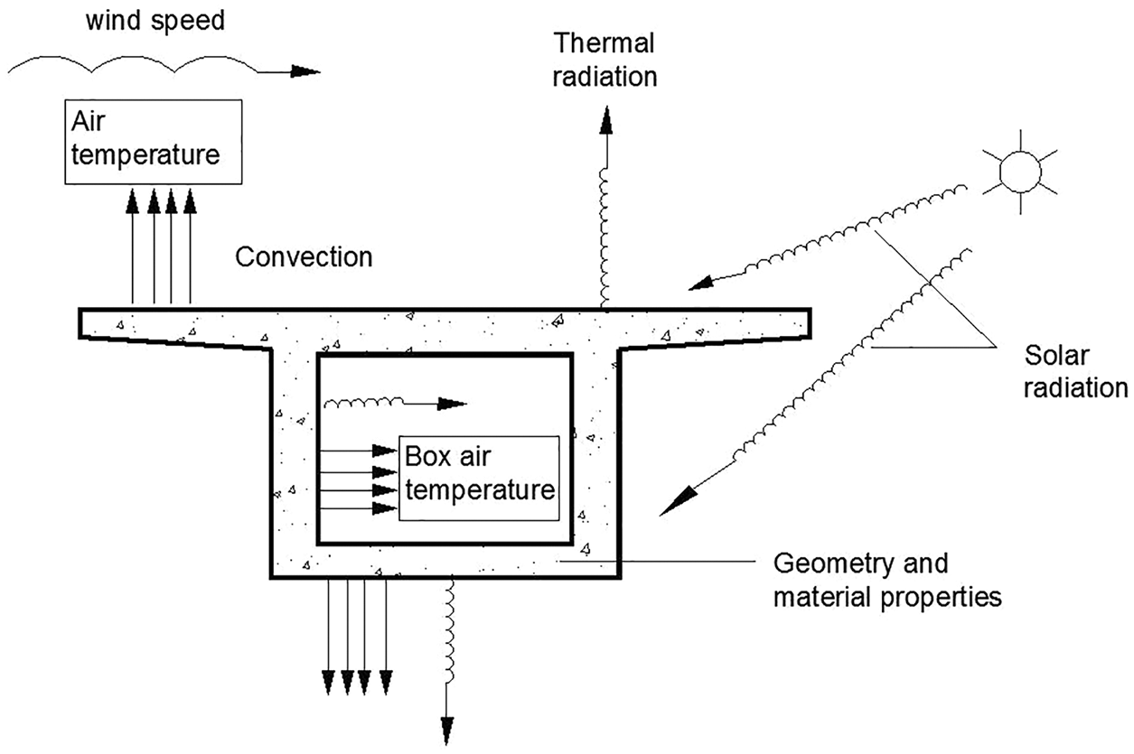
Figure 1: Schematic diagram of environment-bridge interaction
2.2 The Comparison Design Positive Thermal Gradient Code
The famous design gradient from the New Zealand Code and AASHTO LRFD are compared, as shown in Fig. 2. The New Zealand Code is a fifth-order curve decreasing from maximum temperature T0 at the top of deck to zero at a depth of 1200 mm (47.2 1n.) defined by [22]. It was determined that thermal response was affected by three major factors: (1) greater wind speeds, (2) days with the greatest ambient air temperature, and (3) bridge deck, thickness affected thermal response.
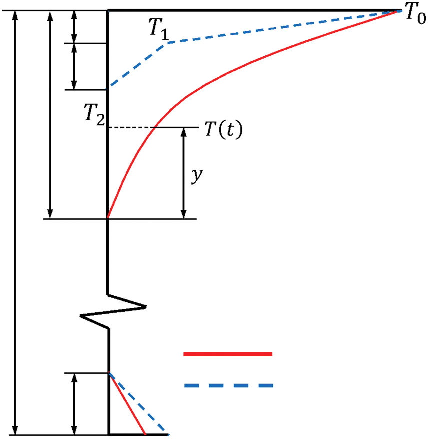
Figure 2: The New Zealand code and AASHTO LRFD. The y is in millimeters and is defined positive up from the point 120
The specified maximum temperature
The temperature distribution along height and width direction is given by the Chinese Code Tb/10002.3-2005, as shown in Fig. 3. The temperature distribution along the vertical direction for a ballast bridge deck is
where
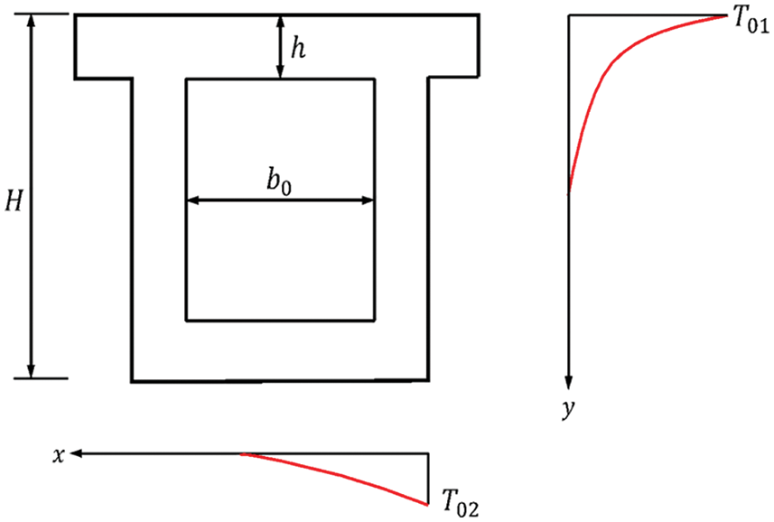
Figure 3: The code Tb/10002.3-2005
3 The Analysis of Ambient and Box Girder Inner Temperature
The detailed meteorological data shows the monthly summary temperature in Fig. 4. Fig. 4 indicates that the summer is more relaxed. The highest temperature is above 30, while the coldest is below −20. The maximum range of temperature in the region is over 50. According to the record, it is windy all the year, with the east and south wind being the main in summer and the northeast and cold southwest wind being the main in winter. Affected by the local altitude and the mountain topography, the wind speed in this region is 5–15 km/h, accelerating the heat flow.
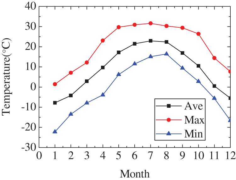
Figure 4: The monthly summary temperature
3.2 The Bridge Girder Parameter
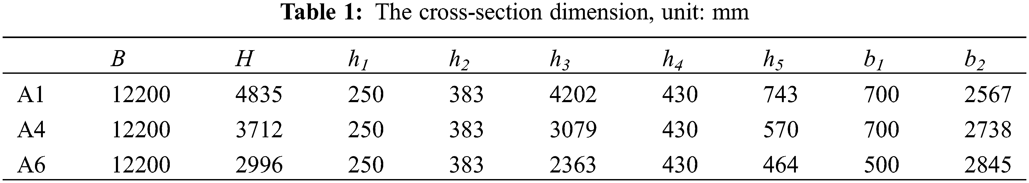
This project is a reinforced concrete bridge with an elevated high-speed railway. The span of the continuous beam is 32 m, and the construction method of an on-site hanging basket cantilever is used. Each beam consists of 8 beam segments, as shown in Fig. 5, and the whole bridge consists of 39 box girders. In this paper’s girder A1, A4, and A6 temperatures were numerically simulated and monitored. The cross-section diagram and dimensions of girders A1, A4, and A6 are demonstrated in Fig. 6 and Table 1. More details of bridge girder modeling can be found in Cai et al. [3] and Sheng et al. [23].
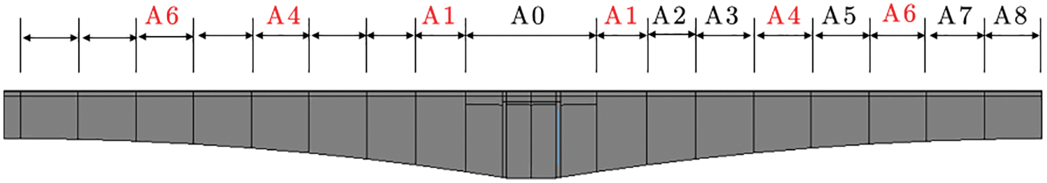
Figure 5: The 1/2 bridge model with portion box girders
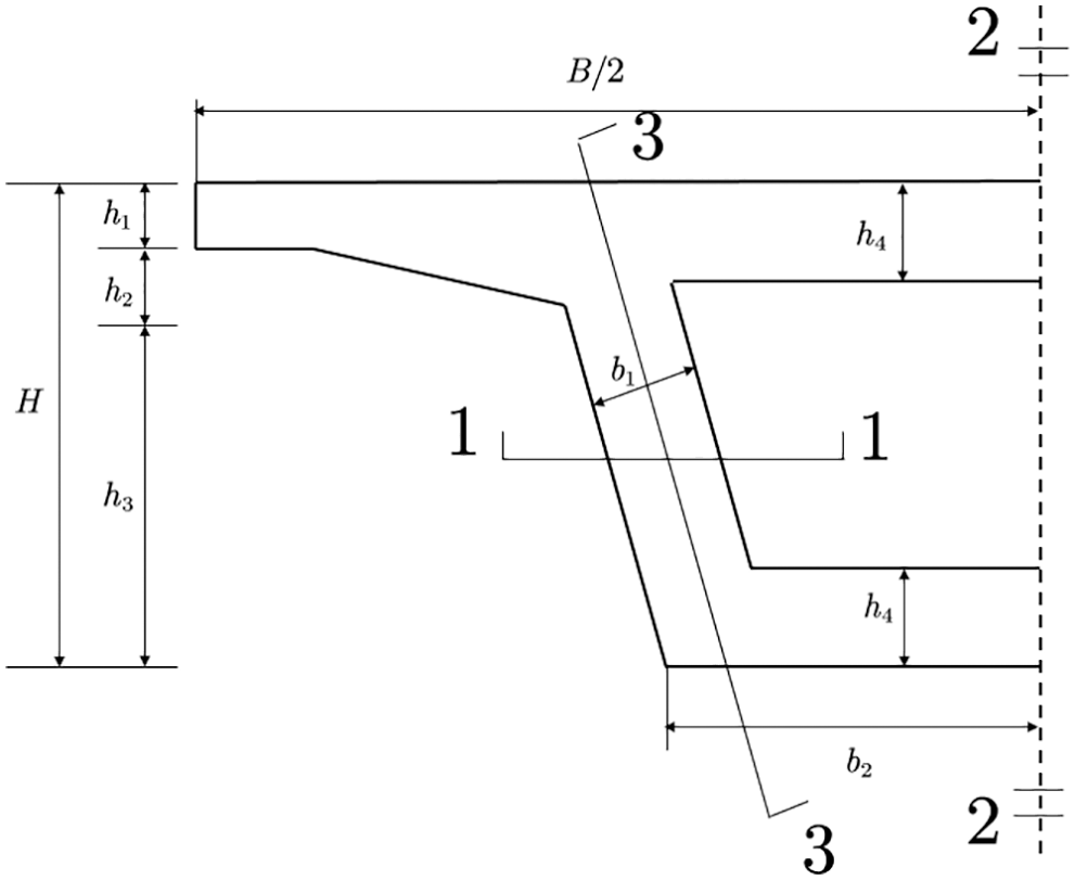
Figure 6: The cross-section diagram
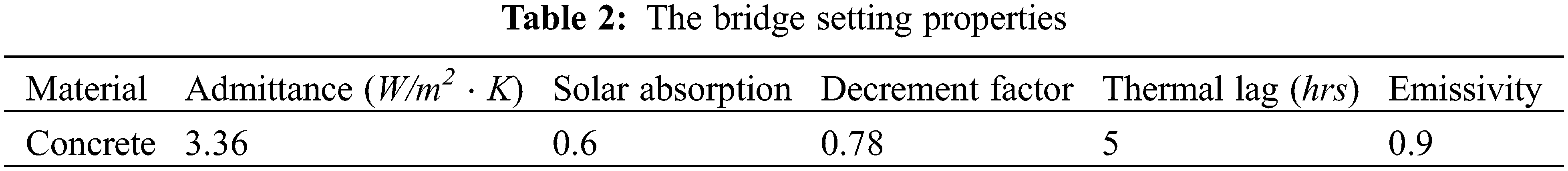
The bridge project is on-site pouring. Therefore, its top, bottom, and bridge webs properties are listed in Table 2.
The model was built using the Zone Block and Void Element. Put the bridge girders into the analysis platform, loading the local topography and meteorological characteristics; then the single calculate model is built. Fig. 7 shows the annual sun path of the A1 girder.
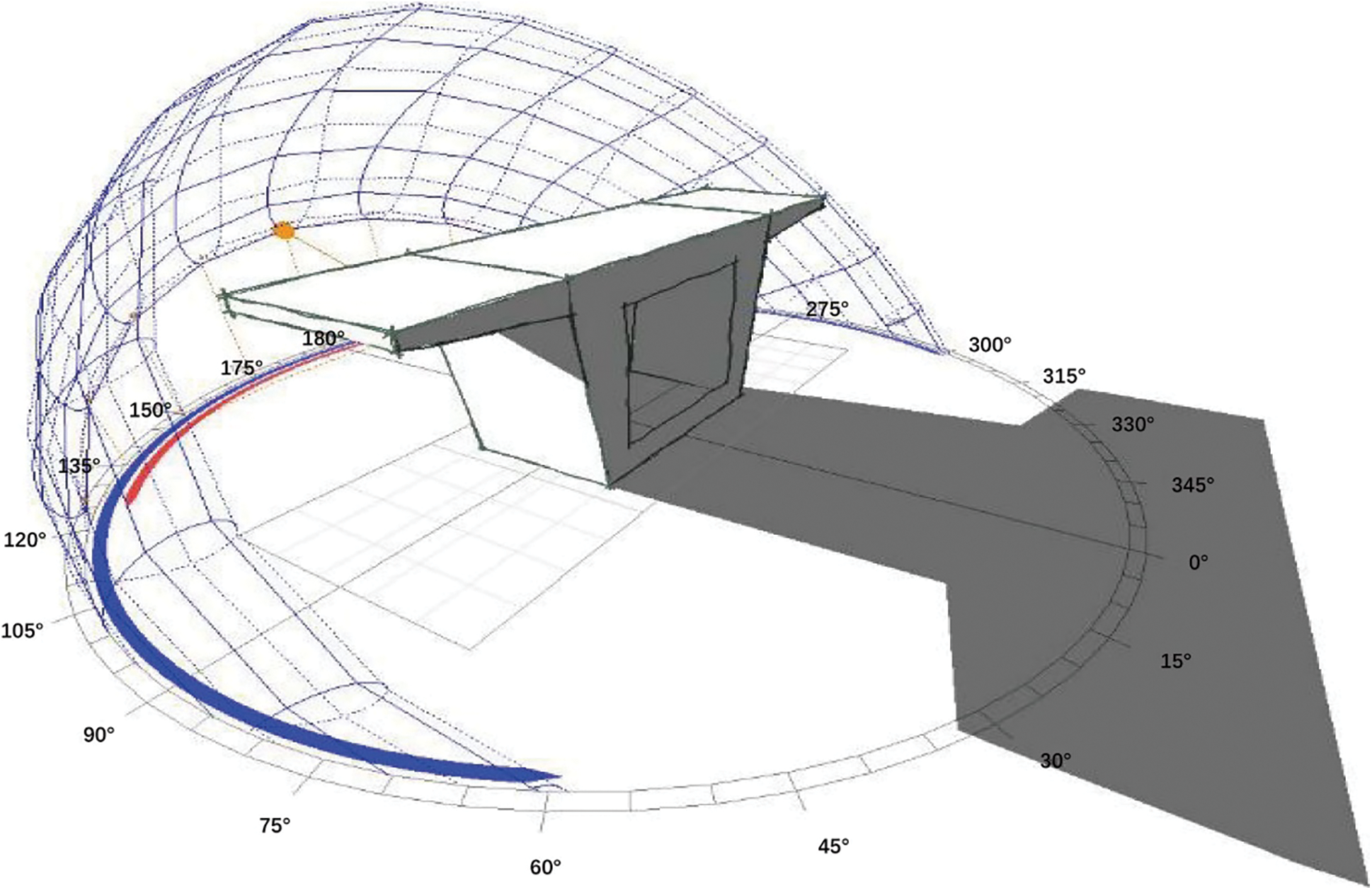
Figure 7: Shadow setting analysis and calculation model
3.3 Measured of the Box Girder Inner Temperature
Simulation of the box girder’s inner temperature was conducted in Ecotect. Ecotect is a green building environment evaluation and design software; the primary purpose is to conduct indoor heat gain and heat dissipation research in residential buildings. The box girder bridge model is set up by establishing solid blocks and hollow blocks. Specifying concrete and air thermodynamic parameters defines model properties and environmental conditions. The focus is on obtaining the internal air environment temperature instead of calculating the temperature change of the concrete unit. When verifing the simulation data, the field temperature was measured during the bridge’s construction. The bridge is a reinforced concrete cast-in-place structure. Construction of box girders A1, A4, and A6 was completed on March 4th, April 9th, and May 3th, respectively. Ambient temperature and box girder inside temperature was measured between 13:00 and 14:00 when the ambient temperature was the highest in the day. The temperature inside the box girder was measured by placing a thermometer on the inner surface of the girder. The thermometer was 1.5 m away from the bottom slab, avoiding direct sunlight. According to local meteorological conditions, some sunny weather days were selected to make temperature measurements. The data and comparison are shown in Fig. 8.
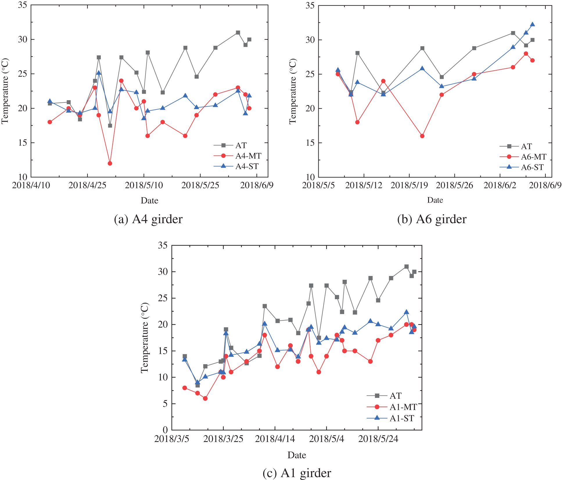
Figure 8: AT, MT and ST of the three girders. AT denotes the date’s ambient temperature, MT denotes the measured temperature, ST denotes the numerically simulated temperature
As shown in Fig. 8, the box girder inside temperature was generally increased during the bridge construction, with a similar trend of weather temperature. After the completion of A1 construction, the A1-MT and A1-ST were consistent with AT because the outermost section was in contact with the outside. The same variations were found in cases of box girder A4 and A6. As the construction was ongoing, increments of A1-MT and A1-ST were less than that of AT. The longer bridge was built, the greater the temperature difference. From the last three days’ average data, the measured temperature of A1, A4, and A6 inner box girders are 19.6, 21.6, and 27.0, while the numerical simulate temperature is 19.6, 21.5, and 30.4, corresponding to the ambient temperature is 30.1.
A bridge’s vertical and transverse temperature gradient usually refers to the ratio of the temperature difference to the bridge size at the top and bottom flanges of concrete box girders. The temperature gradient in the box girder could be defined as
Choosing the date May 08 to June 07, the temperature gradient inside the box girder between A1 to A4 and A4 to A6 can be available.
From Fig. 9, we can see that the A4 to A6 MT and ST gradient are higher than A1 to A4. The beyond temperature gradient on average of MT and ST are 0.25 and 0.69, which shows the end of the box girder section under solar radiation has a larger temperature gradient change than the middle part. Fig. 10 shows the value of (ST-MT)/MT.
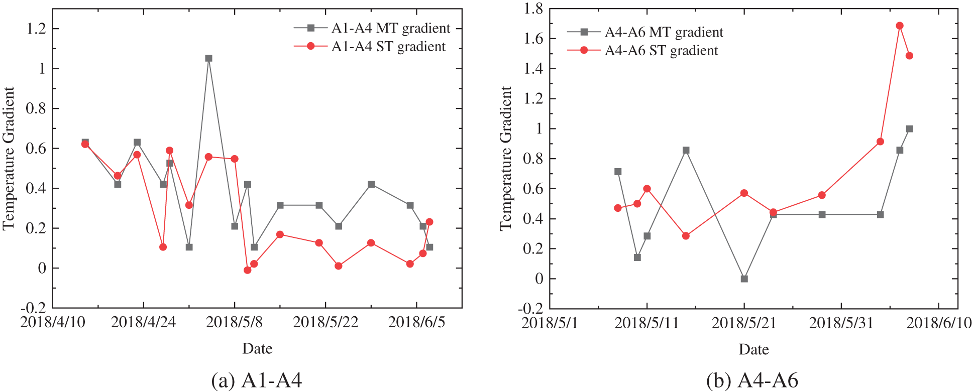
Figure 9: The temperature gradient of inside box girders
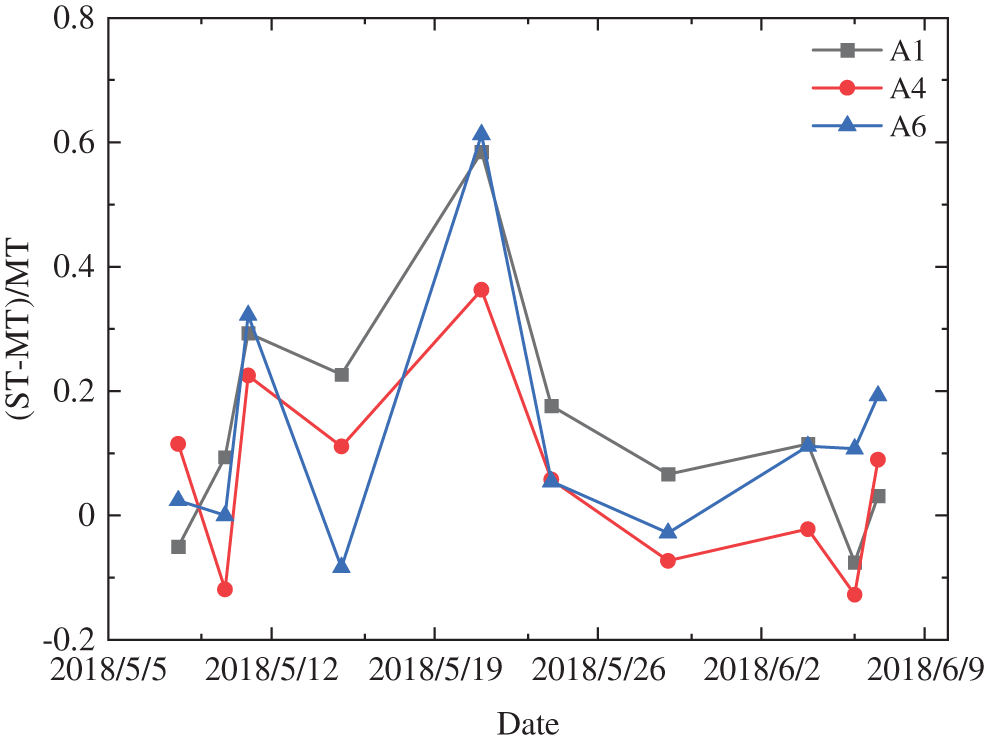
Figure 10: The value of (ST-MT)/MT
3.4 Numerical Simulation of the Box Girder Extreme Weather Temperature
Considering there are under-construction and construction completed stages of the bridge, which are distinguished by whether the outermost section is closed. It is a chance to simulate the inner box air temperature under Extreme weather in two stages of the bridge.
During the bridge construction, the cavity runs through the inner chamber of the bridge. The wind can go through the bridge in the hollows, and solar radiation can get into the girders. The heating, ventilation, and air condition system choose natural ventilation to fit natural environmental conditions. Taking off the hours of air operation to make the concrete’s thermal effect depend on the ambient temperature effect. Loading the local weather condition into the software and simulating box girders separately, the hourly coldest and hottest day temperature during the bridge construction is available.
The coldest day occurs on January 04 (Fig. 11a), while the hottest day on May 17 (Fig. 11b). During the construction, the bridge is most affected by the external environment because the wind can go through the void. In the winter morning and noon, the inside of the box girder temperature is 2–4 degrees higher than the ambient temperature, which has the same inside and outside temperature value in the evening. The summer temperature is high, and the box air temperature changes the corresponding external temperature. From Fig. 11b, the temperature is 5°C–6°C above the external temperature at 3 a.m. The highest box girder inside air temperature usually appears at 2 p.m., hitting the highest ambient temperature in the day.
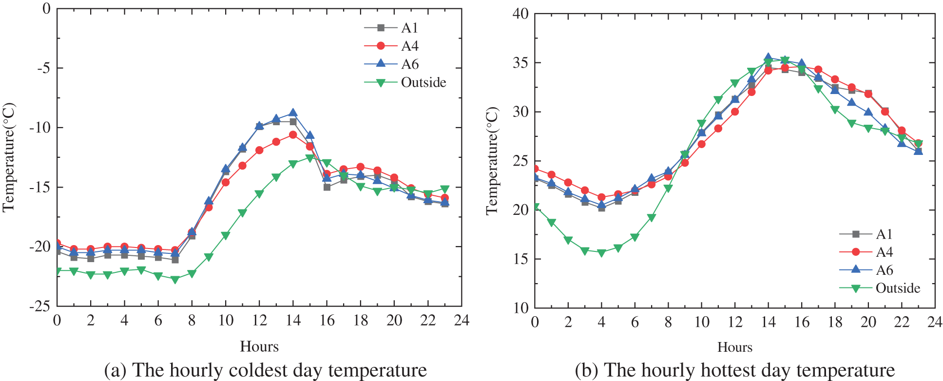
Figure 11: The girder temperature during the bridge construction
When the bridge is built, the voids are connected. Therefore, the internal cannot make heat exchange with the outside directors, and the wind cannot go through the bridge in the hollows either. This will affect the temperature changes in the box girder to be gentle. The January 04 (coldest day) and May 17 (hottest day) weather profiles are used again to simulate each box girder inside temperature under construction completed state (Fig. 12).
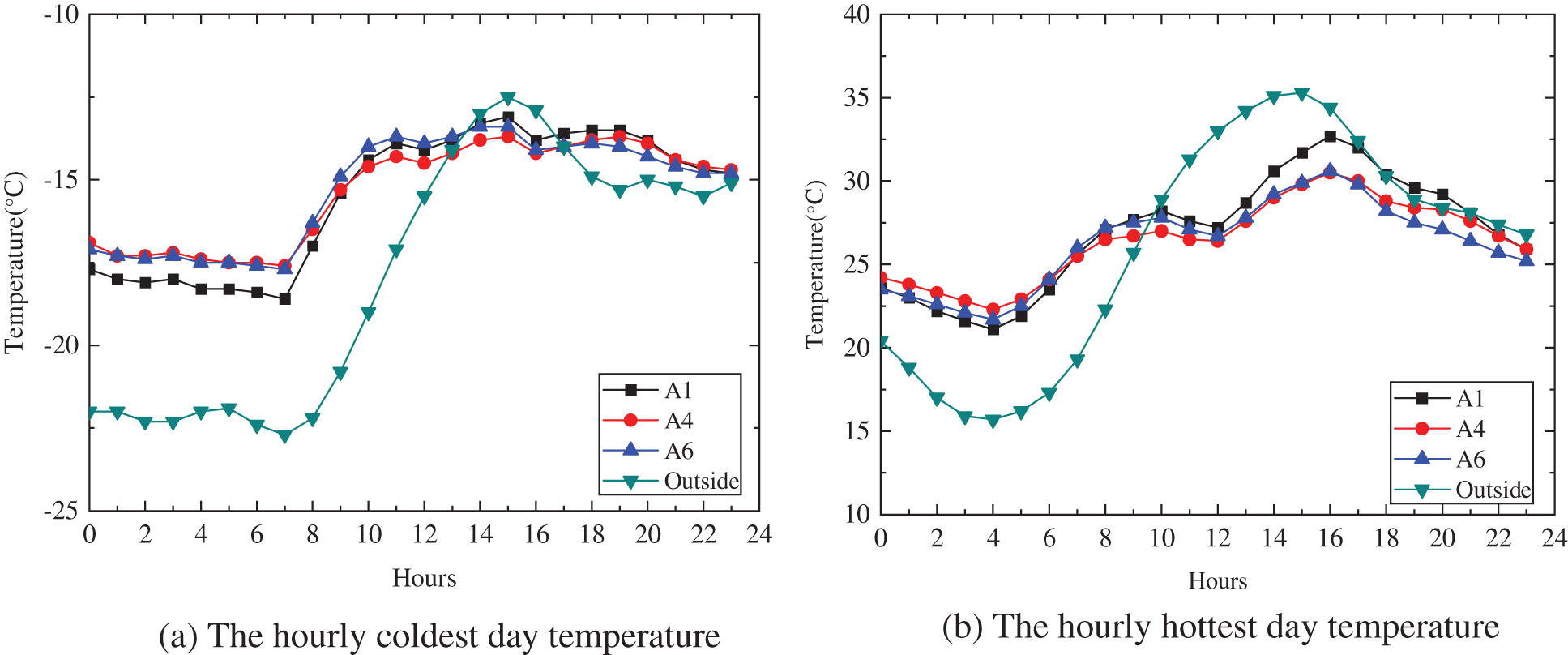
Figure 12: The girder temperature after the bridge construction
After the construction, the outer surfaces of the top and bottom slab are directly affected by the external environment, while the inside void is not. Above the data, the box air temperature change is slightly slower than the external temperature change. In the winter morning, the temperature tends to a constant value of 5°C over the external temperature. The inside of the bridge box girder’s temperature hits the highest at 3 p.m., which is geared to the outside temperature. The inside temperature is 5°C–6°C higher than the environment in summer early morning, which is the same as in winter, and rises until the afternoon. It is slightly lower than the ambient temperature when it reaches the utmost value. In the late evening, it reaches 24°C and tends to be a constant in the late. Comparing the temperature during construction and after construction, It can be seen that the temperature changes of the inside box girder are pretty different. Especially after the construction, there are small changes in magnitude and the rate.
By simulating the construction and post-construction stages of box girders under extreme external temperatures, bridge girders’ internal box, air temperature in summer and winter can be effectively predicted. The results can guide the construction and protection of concrete bridges in winter.
4 The Analysis of Box Girder Concrete Temperature Gradient
In order to determine the box girder concrete temperature, field measurement and numerical simulation is used to determine the concrete temperature and temperature gradient. The thermometers were installed in the construction stage to measure the concrete inside temperature, and the temperature gradients of A1, A4 and A6 are simulated by FE software. The comparison and analysis are as follows.
4.1 The Analysis of Analog Temperature Value and Gradient
As known to all, concrete is a poor conductor of heat. Many scholars have studied the internal temperature changes of box girders and summarized the internal temperature variation rules of concrete. It is found that the internal temperature of concrete has a nonlinear change with the depth of the box girder, and it is close to 5 power functions, as shown in Eq. (4) and Fig. 3. The four site thermal gradients are selected and scaled for the different places. The Chinese Code JTG D60-2015 points to the bridge deck’s maximum and minimum temperature (Table 3).
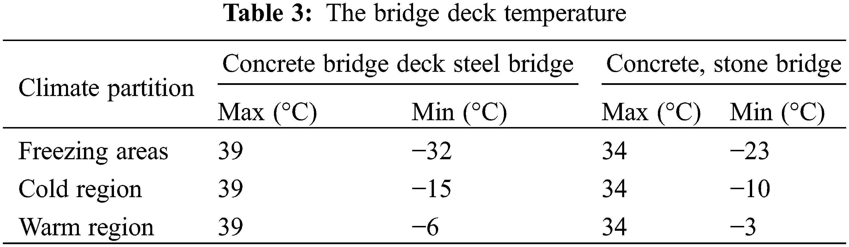
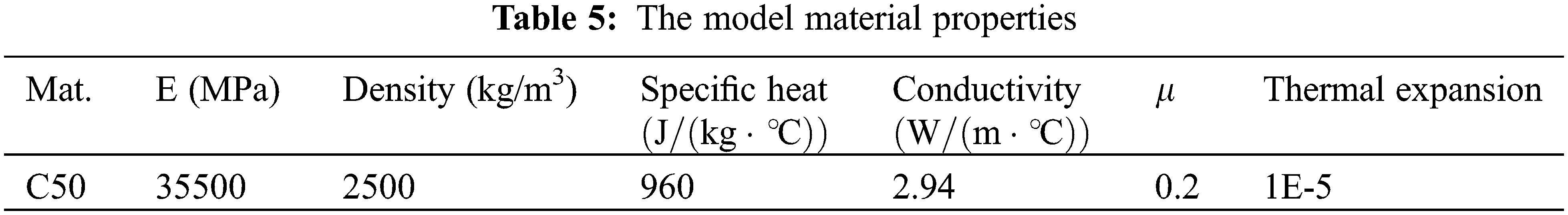
Referring to the simulation of the inside void temperature in Section 3, and the temperature under extreme conditions of the top plate in Table 3, simulating the internal temperature of the box girder concrete can be carried out [12]. The relevant internal and external environmental maximum temperature and the parameters of the model properties are defined as follows (Tables 4, 5).
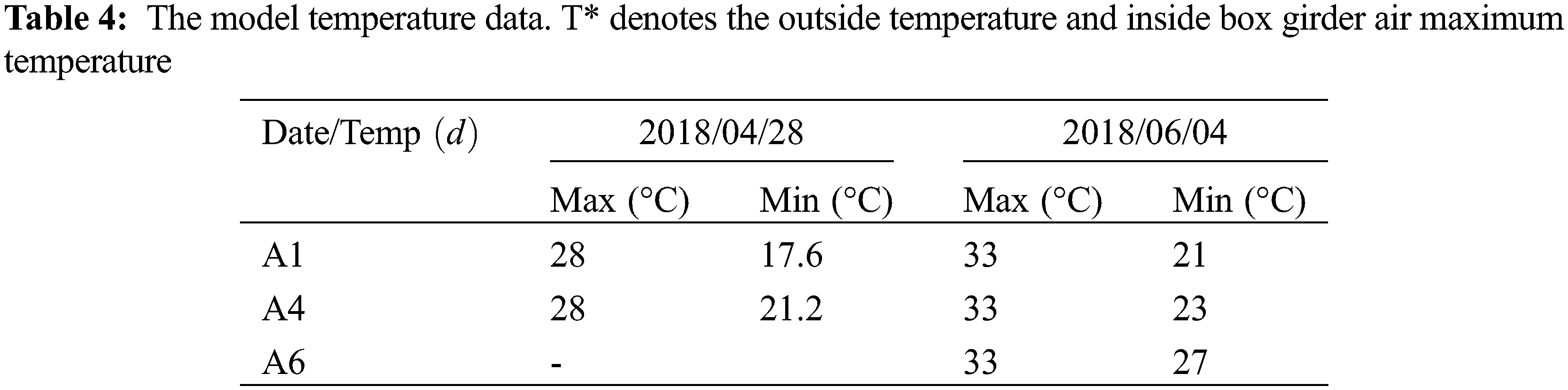
The A1, A4, and A6 box girders are simulated by FE software, considering the construction process. The definition element type is DC3D8, with the seed size being 0.05 m and the field output request is the element temperature (N11). Three box girders numerical simulation results using the model temperature data are available. For further analysis, defining a minimum value of 0 for each set of values, the A1-top, A4-bot, A4-web, and A6-web numerical simulation temperature gradients are as follows (Fig. 13).
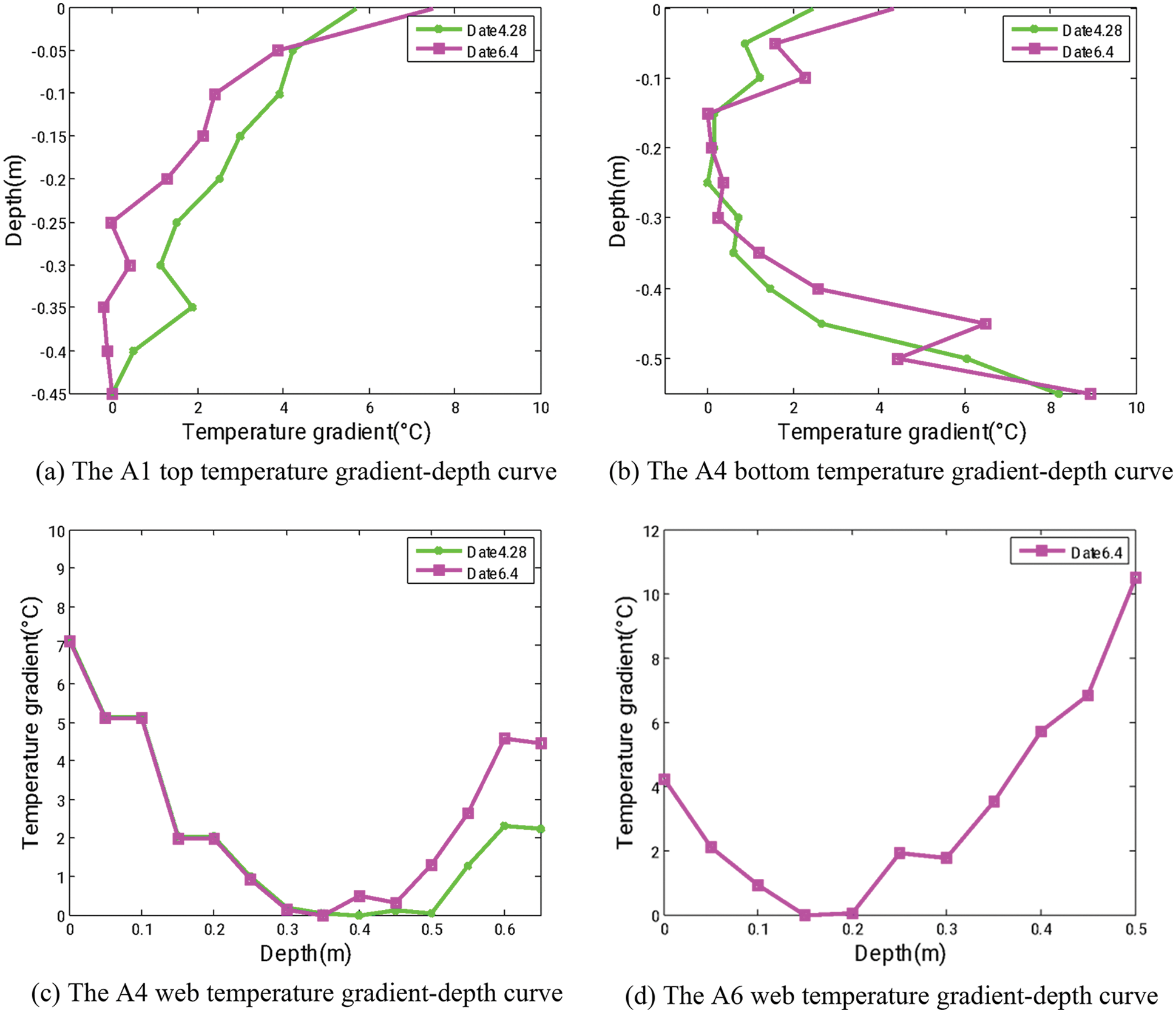
Figure 13: Numerical simulation temperature gradient
It can be seen from the above figure that the temperature gradient of the top and bottom slab is approximate to the power exponential function while the web is closer to the quadratic polynomial. Therefore, the web can be fitted in two parts according to the zero position. According to the numerical simulation result of Date 4.48 and Date 6.4, the fitting of top, bottom, and web are all used in Eq. (5), the power exponent a is calculated, and the following table is summarized.
It can be seen from the above figures that the internal temperature of concrete varies rapidly with the depth of the box girder. Under the influence of different temperature values on the outside and inside surfaces, the temperature gradient showed the same trend, while there is a little change between different conditions. The nonlinear temperature variation pattern occurs at all three box girders in different parts. It is clearly stated that the temperature gradient changes due to the different depths of the box girder section, which affects the inner box air temperature and the thickness of each top slab, bottom slab, and web (see Table 6).
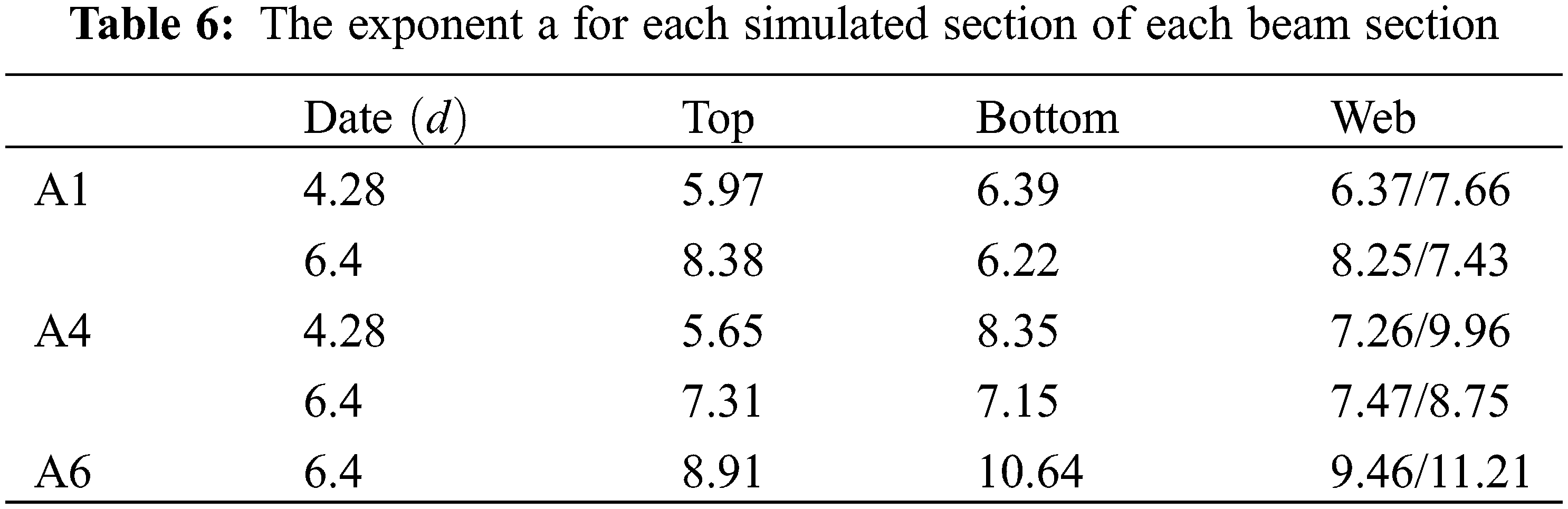
The values of the exponential a in the top, bottom, and web of the A1, A4, and A6 sections are given in Table 6. By comparing each beam section, it is found that with the increase in ambient temperature, the exponential of the top slab and the bottom slab become larger, the web index decreases, and the exponential of the top and bottom slab has a higher rate of change than that of the web. The reason is that the outer side of the top slab is most affected by the ambient temperature, and the outer side of the bottom slab is the least affected, while the temperature outside the web is between the two. Considering that the air temperature in the hole is relatively constant compared to the external temperature, the internal environment of the hole between the top and bottom slab changes more sharply during the fitting, and the coefficient changes more.
The exponential a range is obtained using a function defined by the Chinese specification. For example, the Chinese Code Tb/100023-2005 gives a vertical direction a = 5 and a transverse direction a = 7. It is worth noting that the relevant result is approximately equal to the canonical coefficient.
4.2 The Analysis of Measured Concrete Temperature
In order to verify the validity of the numerical study and get more details about the concrete temperature distribution, 36 thermometers were installed on box girders A1, A4, and A6 during construction (3 thermometers were damaged and have been removed from the statistics, which are on the lower-left corner of A6 section. Fig. 14 shows all section positions of the instrument installation. The distribution of measurement locations was chosen to provide a comprehensive picture of temperature gradients in both the vertical and transverse directions. As we can see, sections A1 and A4 mainly tested the top and bottom slabs of concrete, while section A6 is focused on the web. Considering the height of the box girder section gradually shrinking, the position of the thermometers has been adaptive adjusted. Notably, the web size is changed from 700 to 500 mm, and three horizontal thermometers are arranged equidistantly within the cross-section, as shown in A4 and A6.
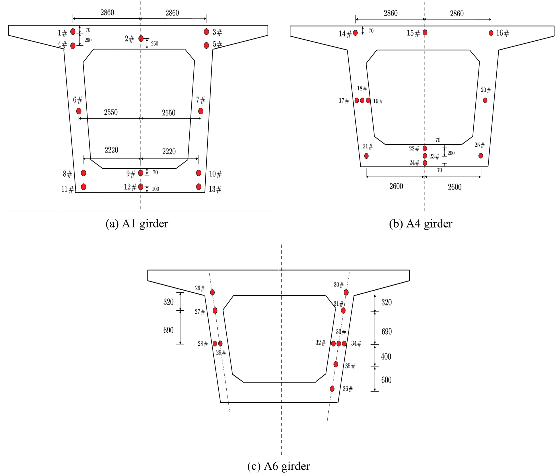
Figure 14: Section position of the instrument installation
In the field measurement, 9 and 15 o’clock are two times in one day to be carried on operation in the spring and summer. Connecting the temperature values of each time point in different periods can get the following Fig. 15. Generally, the daily maximum vertical gradient was observed near the time of maximum solar radiation, approximately 3:00 p.m. The temperature commonality measured at two moments is that (1) the maximum slab surface temperature is the highest of all the measured data. (2) the inside concrete temperature decreases as the depth increases. Because the web is thin (A1 and A4 are 700 mm, the A6 is 500 mm), the temperature in web concrete has little change in contrast with the top plate at the 9 a.m., as well as in the bottom course, there is no direct sunlight, the temperature of the bottom slab is not as high as the top plate. So, the internal concrete temperature is greatly affected by the box girder inside air temperature. At 15 o’clock, the top, bottom, and concrete web temperatures are much higher than in the morning. The web and bottom concrete temperatures rise because there is direct sunlight to the web, and the ambient temperature is up. Direct sunlight and diffuse reflection have a significant influence on concrete temperature. This is why the temperature value of the web is higher than that of internal thermometers on the top and bottom slabs. The three segments also have similar situations.
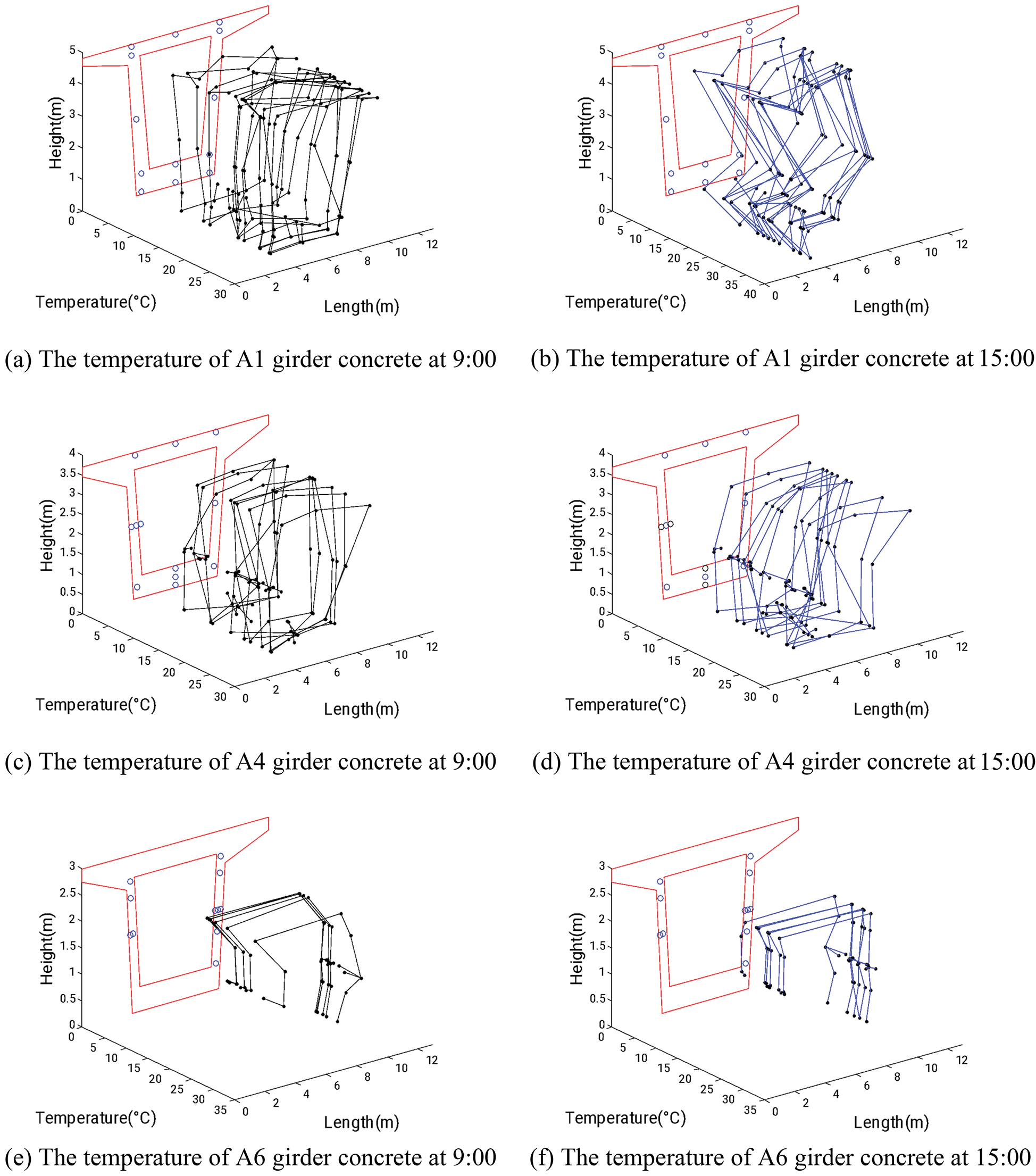
Figure 15: The temperature of girder concrete at each time point
4.3 The Analysis of Measured Full Section Concrete Temperature
In order to better show the daily temperature change of concrete, two days of spring and summer were selected, and temperature monitoring was carried out throughout the day (From 8 a.m. to 5 p.m., monitoring every two hours. The data is also used in 4.4 and 4.5). The section is made obliquely along with the web (Section 3, shown in Fig. 6). The temperature data in the depth direction is as shown in Fig. 16. Choosing two days’ data of three girders, the temperature gradient value can be determined and compared with the three gradient values given in the specifications (Fig. 17). As can be seen from Fig. 17, the greater the depth of the oblique section, the better the measured value and the norm curve fit. Considering the number and depth of the thermometer at the cross-section, the values of the top and bottom plates of the A1 section are closest to the norm. The higher the external temperature, the smaller the difference between internal and external temperature. It shows that the smaller the difference in the internal gradient of concrete, the more deviated from the fitting line of code.
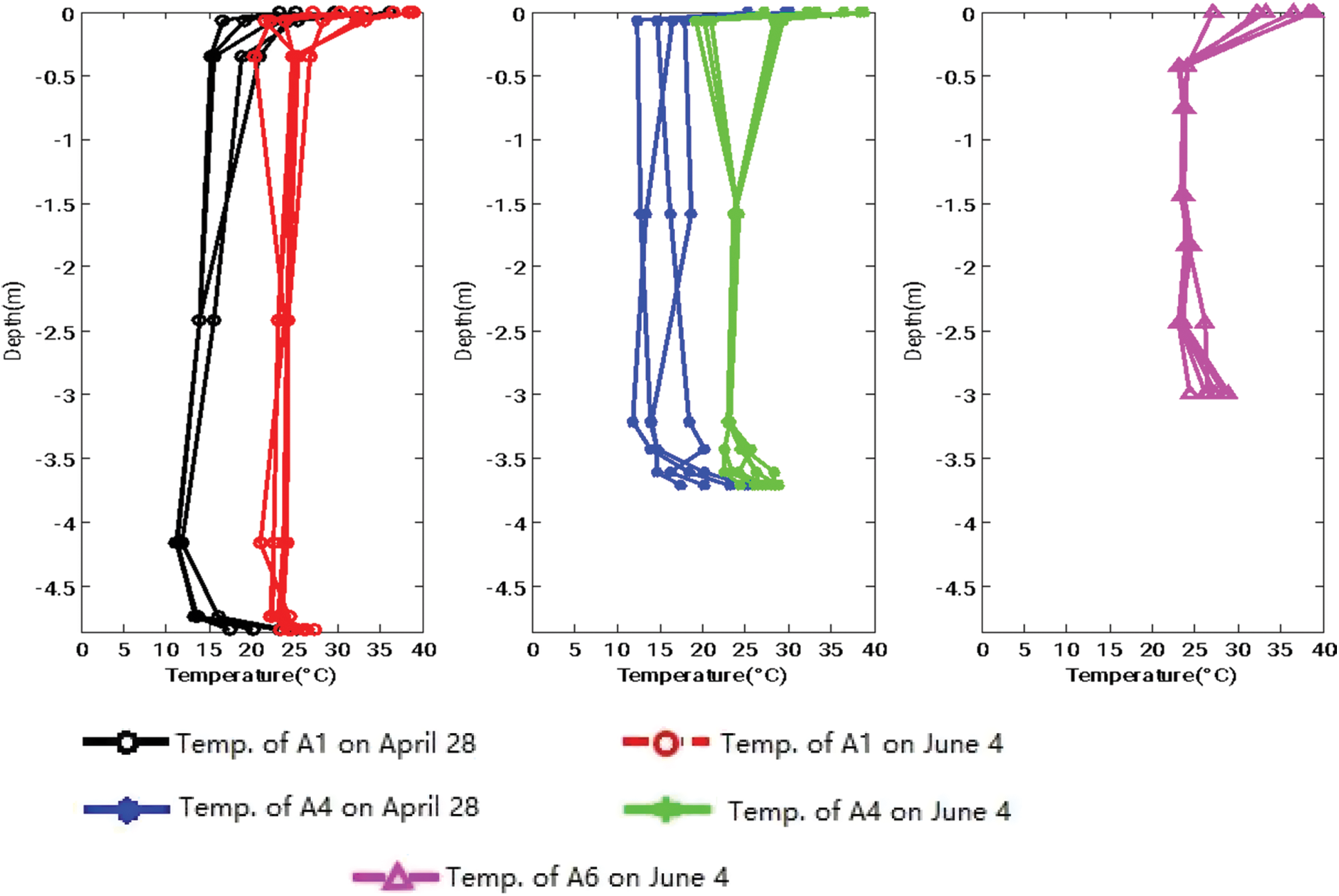
Figure 16: The total cross section temperature of three girders concrete
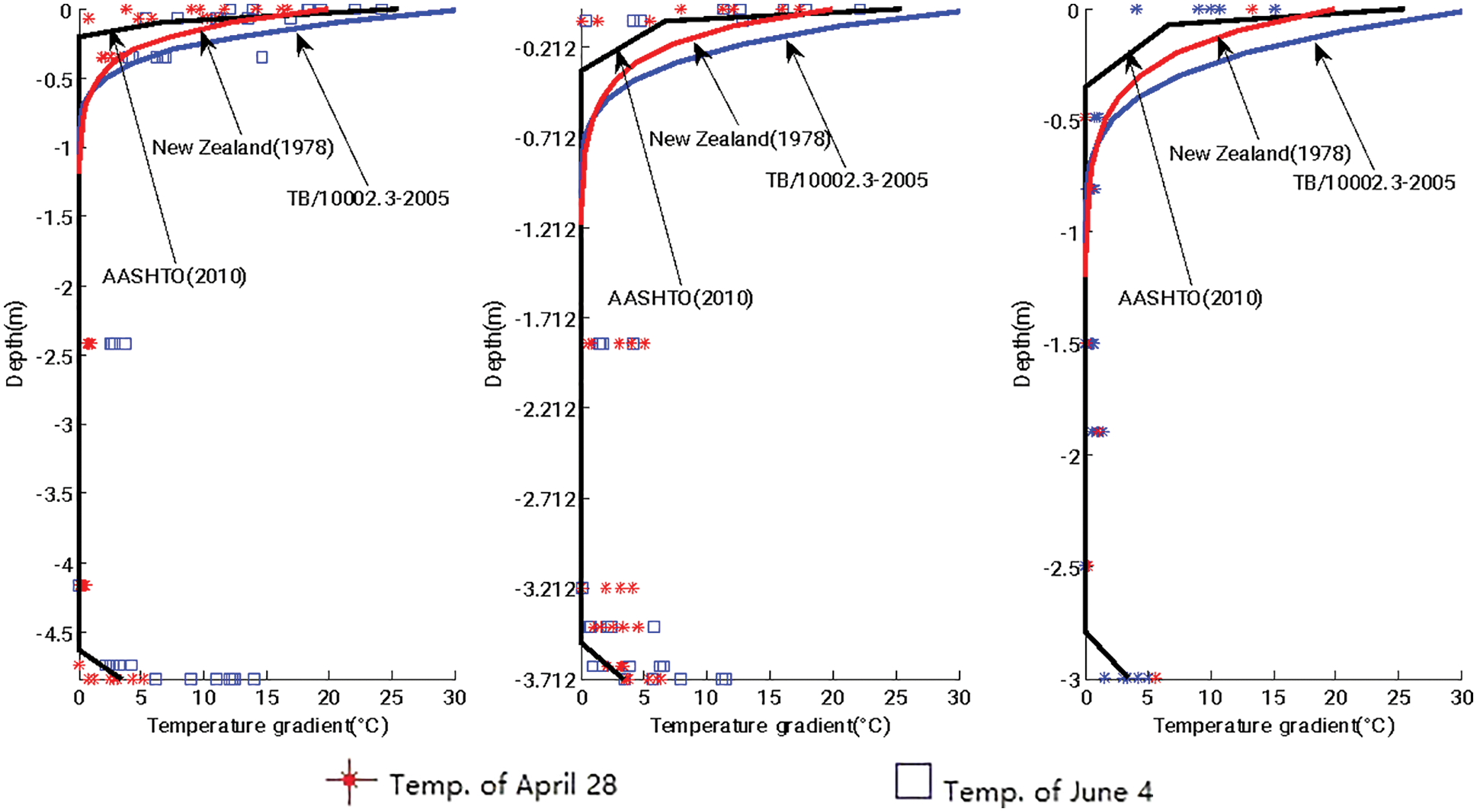
Figure 17: The temperature gradient of measured date with specifications
4.4 The Analysis of Different Parts of Concrete Girder Temperature
There are top slab, bottom slab, and the web makes up the full concrete girder section. The following are analyses of the three parts, respectively. Auditing all of the data which has been collected in the two day span (at two hours interval). It is interesting to find that the lowest temperature is usually the value of the nearest inner surface thermometer. For better visual comparison, the gradients have already been adjusted to the minimum temperature at zero, showing only the temperature difference (temperature gradients), not the actual recorded temperature.
Choosing the 1–5 thermometers to figure out the A1 top slab concrete temperature distribution. Fig. 18 shows the two days measured temperature gradient along the depth. Through the temperature gradient-depth data fitting at different times of the day, the exponent comparison of Eq. (5) is denoted by a solid black line. As described above, the exponent comparison is shown in Fig. 19.
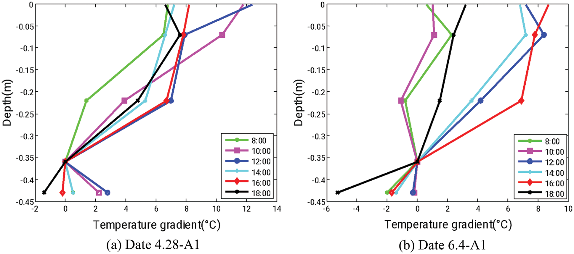
Figure 18: The top slab temperature in two days
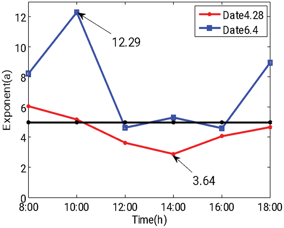
Figure 19: Top’s exponent a comparison
Choosing the 21–25 thermometers to figure out the distribution of A4 bottom slab concrete temperature. Fig. 20 shows the two days measured temperature gradient along the depth. It has to be mentioned that there are only three sets of internal thermometer measurements, causing the outside temperature underlying the A4 cantilever girder bottom cannot be measured. All values have no external concrete temperature, so the beam height of Fig. 20 is
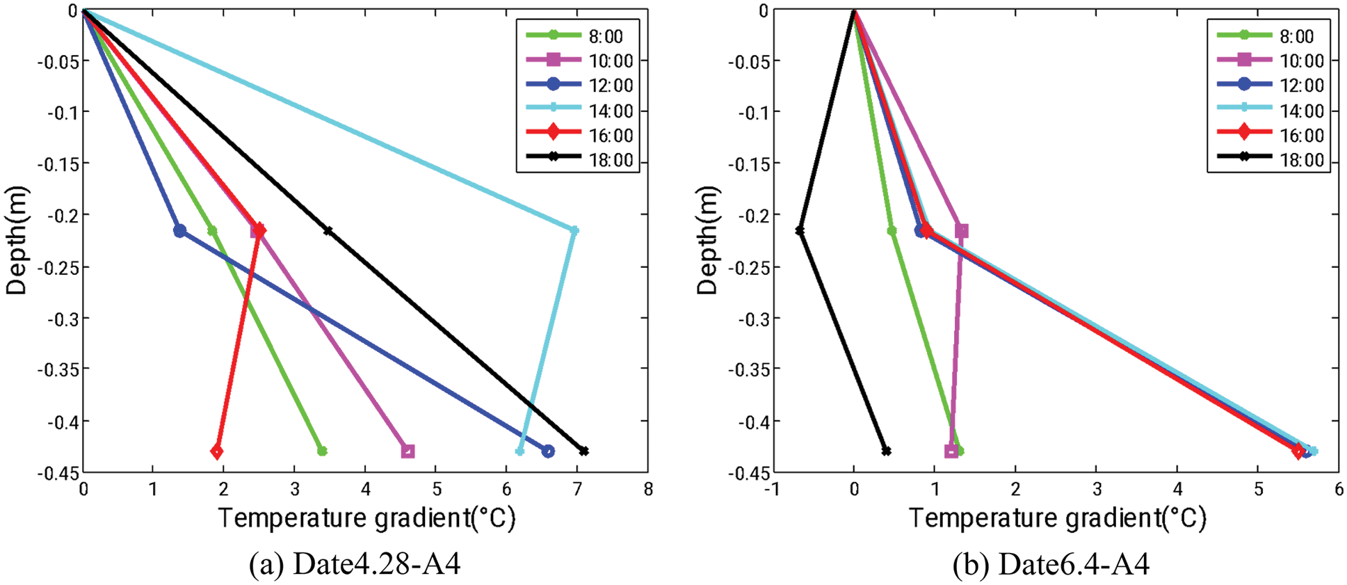
Figure 20: The bottom slab temperature in two days
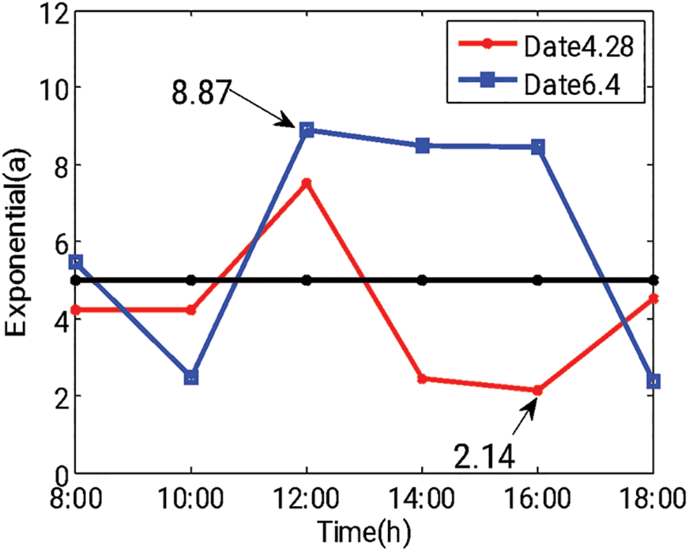
Figure 21: Bottom’s exponent a comparison
Choosing the 17–19 and 32–34 thermometers to figure out the distribution of A4 and A6 web concrete temperature on both sides of the bridge in one day (Date6.4). Unlike the minimum value belonging to the thermometers near the inner wall, the thermometer’s position, which outputs the minimum value in the web concrete, is uncertain. Set the minimum value of each set of internal thermometers to zero, and relative temperature value-depth (temperature gradients) which considering other temperatures, including the inside and outside ambient temperature, is obtained (Fig. 22). From the measured temperature gradient results, the A4 and A6 webs were fitted with an exponential function and the A6 webs were fitted with two exponential functions to obtain the Figs. 23a and 23b, respectively.
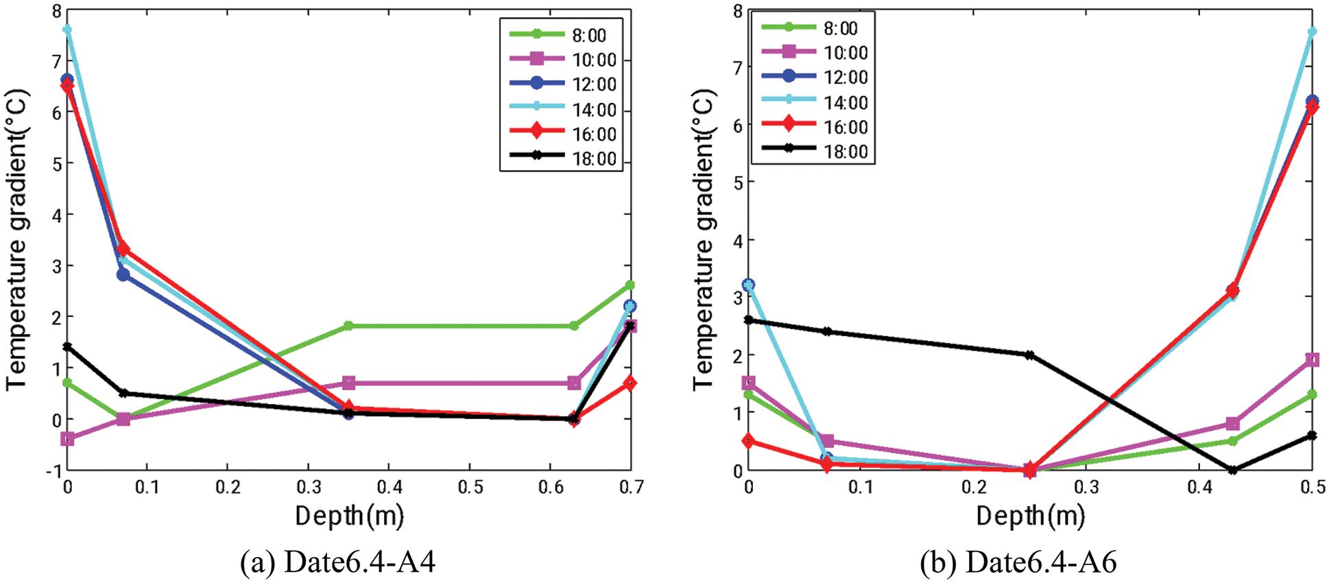
Figure 22: The web temperature in two days
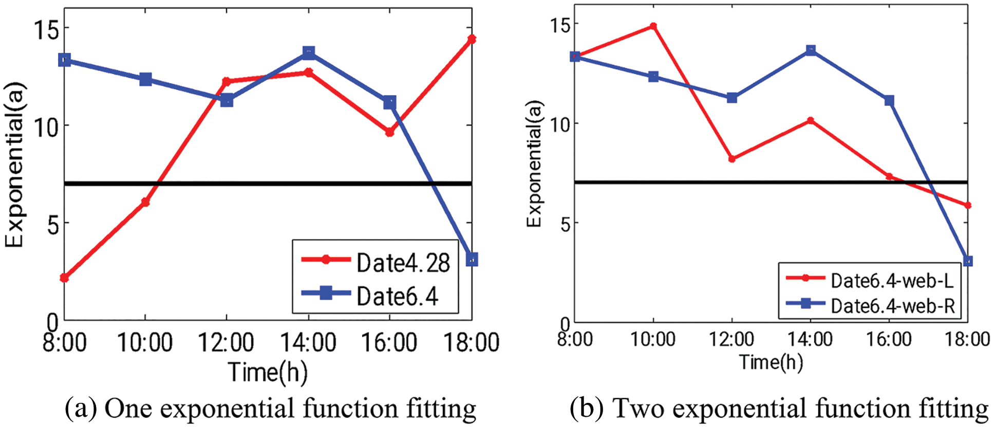
Figure 23: Web fitting exponent a
As seen from the above graph, the rate of change of the internal temperature gradient of the concrete during the day fluctuates with the change in the outside air temperature. The top slab’s temperature change rate is significant in the morning, while the bottom slab hits the most effective change rate in the afternoon. The web’s temperature change rate is reduced from morning to night. For two days in different seasons, the floor and web concrete temperature change rate is reversed due to the increase in seasonal temperature. The black dotted line on the way above indicates the value in the specification. It can be seen that the estimated exponential fluctuates at the realignment.
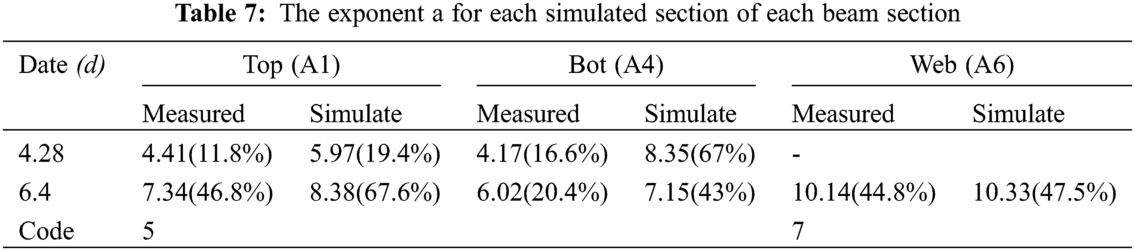
4.5 The Comparison and Analysis of Measured and Theoretical Values
The average value of the an in the above, the Table 6 simulation data, and the norms data are arranged as follows (Table 7), where the errors between the data and the norms data are shown in parentheses. It can be found that the exponent a in the formula is more accurate in solving the temperature gradient change after floating 20%–40% based on the criterion for the higher temperature condition.
The box air temperatures in the highest and lowest ambient conditions in the bridge construction and operation are simulated by the Ecotect software. It provides a new method for predicting the air temperature of the internal box girder bridge at different stages of construction. The main conclusions drawn from this simulation and experimental study are as follows:
• A large daily temperature variation of different girder sections is obtained, which are the most important contributing factor to the temperature gradients. Temperatures measured using thermocouple probes in different positions were accurately collected in this research.
• The current design standards do not accurately predict thermal gradients in concrete box girders (not yet paved with ballast). According to the Chinese code, the index a in the concrete temperature formula for ballasted bridges rises by 20% to 40%. It is closer to the actual temperature gradient change at the construction site. When the web is thin, the temperature gradient of the web can be improved by using two power exponential functions.
Acknowledgement: Thanks to the support of the Taishan Scholar Priority Discipline Talent Group Program Funded by the Shandong Province, and the First-Class Discipline Project Funded by the Education Department of Shandong Province. At the same time, thank the technical staff of China Railway 20th Bureau Group Second Engineering Co., Ltd., for their help at the construction site.
Funding Statement: This work was supported by National Natural Science Foundation of China (Grant No. 51778314).
Availability of Data and Materials: Data will not be shared. This research is based on a real bridge project under construction. The simulation and monitoring data are only used for on-site construction guidance and are not released to the public.
Conflicts of Interest: The authors declare that they have no conflicts of interest to report regarding the present study.
References
1. Abid, S. R., Tayşi, N., Özakça, M. (2016). Experimental analysis of temperature gradients in concrete box-girders. Construction and Building Materials, 106, 523–532. DOI 10.1016/j.conbuildmat.2015.12.144. [Google Scholar] [CrossRef]
2. Abid, S. R., Xue, J., Liu, J., Tayşi, N., Liu, Y. et al. (2022). Temperatures and gradients in concrete bridges: Experimental, finite element analysis and design. Structures, 37, 960–976. DOI 10.1016/j.istruc.2022.01.070. [Google Scholar] [CrossRef]
3. Cai, C., Huang, S., He, X., Zhou, T., Zou, Y. (2022). Investigation of concrete box girder positive temperature gradient patterns considering different climatic regions. Structures, 35, 591–607. DOI 10.1016/j.istruc.2021.11.030. [Google Scholar] [CrossRef]
4. Arockiasamy, M., Reddy, D. V., Sivakumar, M., Shahawy, M. (2008). Fatigue loading and temperature distribution in single cell segmental box bridges. Practice Periodical on Structural Design and Construction, 13(3), 118–127. DOI 10.1061/(ASCE)1084-0680(2008)13:3(118). [Google Scholar] [CrossRef]
5. Zhou, G. D., Yi, T. H. (2013). Thermal load in large-scale bridges: A state-of-the-art review. International Journal of Distributed Sensor Networks, 9(12), 217983. DOI 10.1155/2013/217983. [Google Scholar] [CrossRef]
6. Imbsen, R. A., Vandershaf, D. E., Schamber, R. A., Nutt, R. V. (1985). Thermal effects in concrete bridge superstructures. McLean, VA, USA: National Cooperative Highway Research Program. [Google Scholar]
7. Roberts-Wollman, C. L., Breen, J. E., Cawrse, J. (2002). Measurements of thermal gradients and their effects on segmental concrete bridge. Journal of Bridge Engineering, 7(3), 166–174. DOI 10.1061/(ASCE)1084-0702(2002)7:3(166). [Google Scholar] [CrossRef]
8. Branco, F. A., Mendes, P. A. (1993). Thermal actions for concrete bridge design. Journal of Structural Engineering, 119(8), 2313–2331. DOI 10.1061/(ASCE)0733-9445(1993)119:8(2313). [Google Scholar] [CrossRef]
9. Kennedy, J. B., Soliman, M. H. (1987). Temperature distribution in composite bridges. Journal of Structural Engineering, 113(3), 475–482. DOI 10.1061/(ASCE)0733-9445(1987)113:3(475). [Google Scholar] [CrossRef]
10. Au, F. T. K., Cheung, S. K., Tham, L. G. (2002). Design thermal loading for composite bridges in tropical region. Steel and Composite Structures, 2(6), 441–460. DOI 10.12989/scs.2002.2.6.441. [Google Scholar] [CrossRef]
11. Barr, P. J., Stanton, J. F., Eberhard, M. O. (2005). Effects of temperature variations on precast, prestressed concrete bridge girders. Journal of Bridge Engineering, 10(2), 186–194. DOI 10.1061/(ASCE)1084-0702(2005)10:2(186). [Google Scholar] [CrossRef]
12. Lee, J. H., Kalkan, I. (2012). Analysis of thermal environmental effects on precast, prestressed concrete bridge girders: Temperature differentials and thermal deformations. Screen, 47(1), 129–132. [Google Scholar]
13. Swenson, T. (2015). Effect of temperature on prestressed concrete bridge girder strand stress during fabrication (Ph.D. Thesis). University of Minnesota, Minnesota. [Google Scholar]
14. Laosiriphong, K., Gangarao, H. V. S., Prachasaree, W., Shekar, V. (2006). Theoretical and experimental analysis of GFRP bridge deck under temperature gradient. Journal of Bridge Engineering, 11(4), 507–512. DOI 10.1061/(ASCE)1084-0702(2006)11:4(507). [Google Scholar] [CrossRef]
15. Abid, S. R., Tayşi, N., Özakça, M., Xue, J., Briseghella, B. (2021). Finite element thermo-mechanical analysis of concrete box-girders. Structures, 33, 2424–2444. [Google Scholar]
16. Kong, B., Cai, C. S., Pan, F. (2013). Temperature distribution behaviors of GFRP honeycomb hollow section sandwich panels. Structural Engineering and Mechanics, 47(5), 623–641. DOI 10.12989/sem.2013.47.5.623. [Google Scholar] [CrossRef]
17. Numan, H. A., Taysi, N., Ozakca, M. (2016). Experimental and finite element parametric investigations of the thermal behavior of CBGB. Steel and Composite Structures, 20(4), 813–832. DOI 10.12989/scs.2016.20.4.813. [Google Scholar] [CrossRef]
18. Zhou, G. D., Yi, T. H., Chen, B. (2015). Analysis of three-dimensional thermal gradients for arch bridge girders using long-term monitoring data. Smart Structures and Systems, 15(2), 469–488. DOI 10.12989/sss.2015.15.2.469. [Google Scholar] [CrossRef]
19. Zhou, Y., Sun, L., Peng, Z. (2015). Mechanisms of thermally induced deflection of a long-span cable-stayed bridge. Smart Structures and Systems, 15(3), 505–522. DOI 10.12989/sss.2015.15.3.505. [Google Scholar] [CrossRef]
20. Yang, X., Zhang, J., Ren, W. X. (2017). Temperature effect analysis of a long-span cable-stayed bridge based on extreme strain estimation. Smart Structures and Systems, 20(1), 11–22. [Google Scholar]
21. Hedegaard, B. D., French, C. E. W., Shield, C. K. (2013). Investigation of thermal gradient effects in the I-35W St. Anthony falls bridge. Journal of Bridge Engineering, 18(9), 890–900. DOI 10.1061/(ASCE)BE.1943-5592.0000438. [Google Scholar] [CrossRef]
22. Hagedorn, R., Marti-Vargas, J. R., Dang, C. N. (2019). Temperature gradients in bridge concrete I-girders under heat wave. Journal of Bridge Engineering, 24(8), 04019077.1–04019077.14. DOI 10.1061/(ASCE)BE.1943-5592.0001454. [Google Scholar] [CrossRef]
23. Sheng, X., Zhou, T., Huang, S., Cai, C., Shi, T. (2022). Prediction of vertical temperature gradient on concrete box-girder considering different locations in China. Case Studies in Construction Materials, 16, e01026. DOI 10.1016/j.cscm.2022.e01026. [Google Scholar] [CrossRef]
Cite This Article
 Copyright © 2023 The Author(s). Published by Tech Science Press.
This work is licensed under a Creative Commons Attribution 4.0 International License , which permits unrestricted use, distribution, and reproduction in any medium, provided the original work is properly cited.
 Downloads
 Citation Tools