
 Submit a Paper
 Propose a Special lssue
 Open Access
ARTICLE

The Nest of Torquigener Albomaculosus: Fluid-Dynamic Aspects and Potential for Bio-Inspired Engineering
1
School of Electrical and Mechanical Engineering, Pingdingshan University, Pingdingshan, 467000, China
2
Henan Province Engineering Research Center of Ultrasonic Technology Application, Pingdingshan University, Pingdingshan,
467000, China
3
School of Mechanical and Transportation Engineering, Guangxi University of Science and Technology, Liuzhou, 545006, China
* Corresponding Author: Ning Feng. Email:
Fluid Dynamics & Materials Processing 2023, 19(7), 1837-1850. https://doi.org/10.32604/fdmp.2023.026814
Received 27 September 2022; Accepted 14 December 2022; Issue published 08 March 2023
 View Full Text
 Download PDF
Abstract
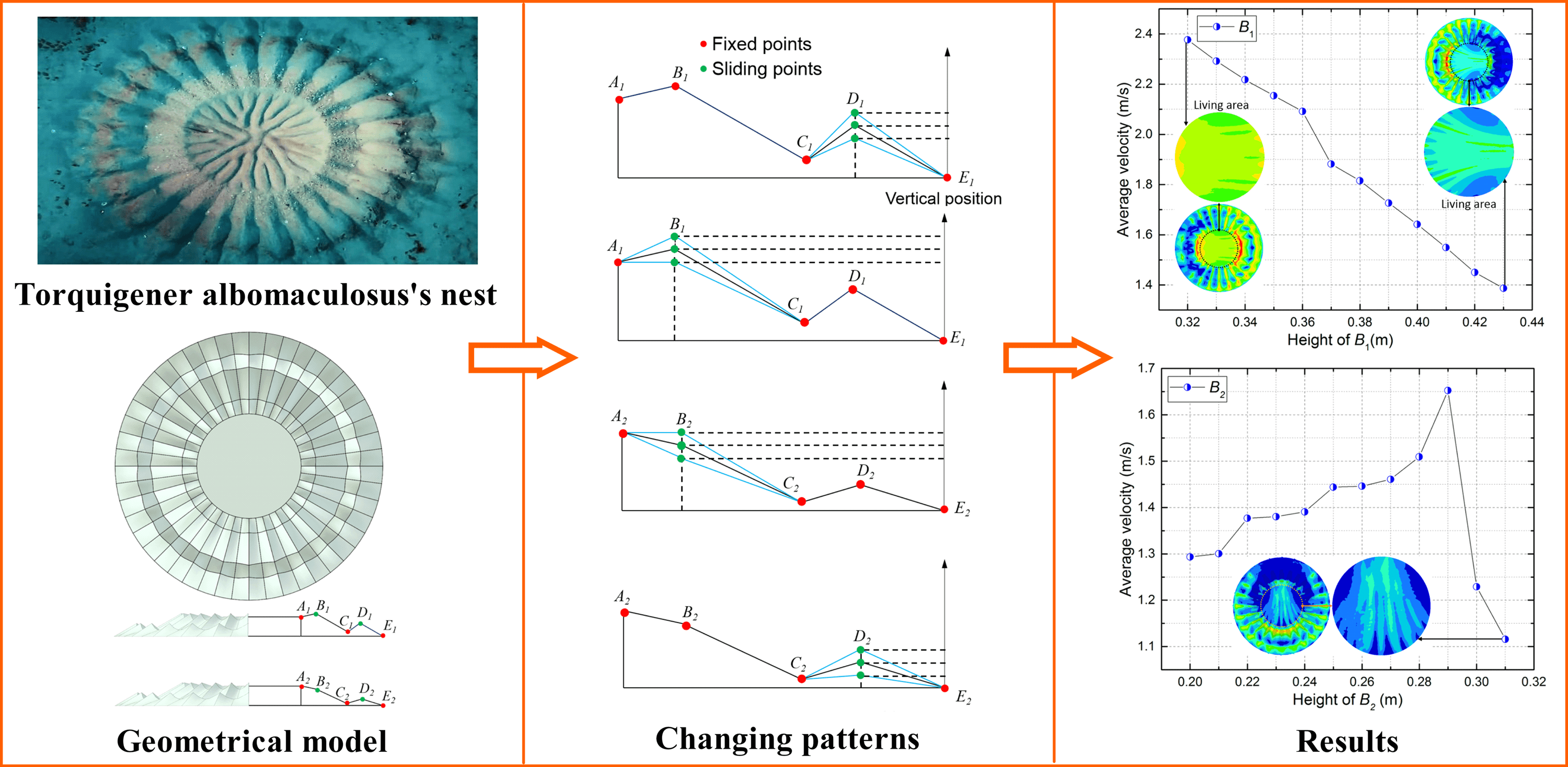
Torquigener albomaculosus, also known as the white-spotted pufferfish, is known for creating circular nests in the underwater sand as part of the mating ritual. The nests are built by the males to attract females through the nest’s impressive design and related ability to gather fine sand particles. As the fluid-dynamic processes associated with these unique nests are still almost completely unknown, in the present study, an analysis has been conducted to investigate how the geometric parameters related to the nest design influence the fluid velocity in its center. For this reason, a geometric model of the nest consisting of 24 channels, where each unit channel can be described by three strips of broken lines, has been introduced, and a multivariate analysis has been implemented to determine the relative weight of each considered parameter. In particular, the “optimal” combination of parameters has been obtained by means of an orthogonal design approach. We show that these bio-nest structures also display a potential for significant application in marine litter collection, or for use as a buffer against the waves in offshore areas.Graphic Abstract
Keywords
The emergence of bionics has led to new levels of scientific research, technological development, and engineering capabilities for applications in human lives [1]. From obtaining natural resources to learning from nature, nature has always inspired humans to come up with many novel ideas and concepts, inspired by those seen in nature. Many flexible, practical, and efficient products have been developed, such as honeycomb structures [2], radar sonar [3], solar applications [4], etc. These are applied in people’s everyday lives and have become a necessity for many.
For thousands of years, humans have continued to observe and study nature, the habits, and the habitats of many different organisms. Different kinds of tools and machines have been invented to effectively solve various technological development problems. This paper is a study of the habitat of Torquigener albomaculosus. Torquigener is a species of fish in the family Tetraodontidae [5]. Over the past 30 years, underwater divers have found some strange and amazing circles on sandy bottoms at depths from 10 to 27 m along the south coast of the Amami-Oshima Island of the Ryukyu Islands [6]. It was only in 2011 that a Japanese underwater photographer, Yoji Okata, observed a pufferfish of the genus Torquigener Whitley building one of these mystery circles [6]. In May 2014, the constructor of these mystery circles was named Torquigener albomaculosus by the research team of the National Museum of Nature and Science [6].
Bionic structural studies are often carried out with the help of computers [7–9]. Numerical simulations such as computer-aided engineering (CAE) [9–12] and computational fluid dynamics (CFD) [13–15] are used instead of experiments, greatly saving costs of time and money. Scholars have used CFD [16–21] and CAE [22–25] methods in the study of nanofluids [26,27], bionic engineering [28,29], engineering architecture [30], and other fields. Computer-aided simulations enable the observation of many details that cannot be captured by experiments, allowing for more in-depth studies. For example, Sachs et al. [16] studied the effects of extremely large dihedral on the aerodynamic characteristics of birds using a sophisticated aerodynamic method. With Sachs’s method [16], it could be observed and confirmed that an extremely large dihedral substantially affects the aerodynamic force characteristics. Meng et al. [17,31] combined experimental measurements and numerical simulations to investigate the kinematic characteristics, aerodynamic performance, and power requirement of ascending flight in fruit flies. Dong et al. [18] presented an innovative design for a biomimetic whale shark-like underwater glider aiming at the combination of high maneuverability and long duration using CFD methods. Previously Feng et al. [22] reported bio-inspired camber morphing structures which were investigated through finite element analysis. The present bio-inspired camber morphing structures can achieve shape-adaptive morphing while the morphing skin is underactuated. In summary, computer assistance enables a more detailed study. This paper uses computational fluid dynamics (CFD) methods to study the fluid behavior of Torquigener albomaculosus nests.
Torquigener albomaculosus builds the mystery circles as their nests. The nest can attract female fish and allows ocean currents to deliver sand into the center of the nest. However, studies focused on the fluid behaviors of these mystery circles are rare. To study these mystery circle nests, firstly, a geometric model of the fish nest is built to ensure maximum consistency with the nests built by the pufferfish. Then, the fluid behavior of the fish’s nest is studied using a univariate fluid analysis method. Only the relative height of a point in the boundary line or median line of the nest is varied to observe the flow characteristics. Finally, the flow characteristics of the nest are studied by multivariate analysis, and the optimal solution of the nest model is obtained by the orthogonal test method. It is verified that it has the lowest average speed in the living area. The bio-nest structures show a significant potential for a possible application for reducing the impact of ocean currents in offshore areas or the flushing of quicksand in the desert.
2 The Analysis Model for the Nest of Torquigener Albomaculosus
2.1 The Nest of Torquigener Albomaculosus
The model was derived from the nest of Torquigener albomaculosus, a kind of fish living in the Pacific Ocean. The geometric model of the constructed nest is ensured to be maximally consistent with that built by Torquigener albomaculosus, as shown in Fig. 1. Regarding the proportions of the prototype, the overall outer circle diameter of this nest is set as 2 meters (m), while the central part of the nest (the area where Torquigener albomaculosus live) is set as 0.8 m in diameter. Fig. 1 shows that this symmetrical nest is made up of several channels, which can effectively reduce the impact of the ocean. On the one hand, the male fish constructs it to attract female fish. On the other hand, the channels can draw the sand from ocean currents into the nest’s center.

Figure 1: The prototype of the nest built by torquigener albomaculosus
Three critical broken lines describe one channel unit (Fig. 2), the two lines on either side are boundary lines of the channel. They have the same geometric features, and the middle line represents the channel’s bottom line. Each of the three broken lines has five points Ai, Bi, Ci, Di, and Ei (Fig. 2b). The channel’s surface is formed smoothly by three broken lines. The geometric model of the whole nest can be obtained by duplicating and rotating the surface of the channel unit. To study the fluid behaviors of the models by changing and comparing the parameters of the geometric model, the points Ai, Ci, and Ei are set as fixed points, and the points Bi and Di are set as moving points in the vertical direction.

Figure 2: Unit of the channel in the model
2.2 The Geometric Models of the Nest of Torquigener Albomaculosus
Upon observing the established geometric models of the nest, first, we consider that for fluid analysis, the shapes of the boundary lines (A1-E1) and the middle line (A2-E2) change independently and respectively. Then the shapes of the boundary lines (A1-E1) and the middle line (A2-E2) are constructed to change simultaneously for fluid analysis in this study.
Fig. 3 shows the boundary lines (A1-E1) and changes in the unit channel with the top and front views. As seen in Fig. 3b, point B1 is a moving point that can slide vertically, while points A1, C1, and E1 are fixed points. The shape of this group of geometric models is changing consistently with this law for the next fluid analysis.

Figure 3: The geometry of the nest compared to the boundary lines (A1-E1) are changing: (a) the top view and the front view; (b) changing style of the middle lines (A1-E1)
Similarly, the changing rule of the middle lines (A2-E2) of the channel unit with the top view and the front view can be seen in Fig. 4. Here the point B2 is set as a moving point that can slide vertically, while the points A2, C2, D2, and E2 are set as the fixed points. The shape of this group of geometrical models is changing consistently with this law for the next fluid analysis.

Figure 4: The geometry of the nest compared to the boundary lines (A2-E2) are changing: (a) the top view and the front view; (b) changing style of the middle lines (A2-E2)
Based on the results of the fluid analysis of the stated geometric models, a group of orthogonal experiments were conducted to study the fluid behaviors of the nest, while the shapes of the boundary lines (A1-E1) and the middle line (A2-E2) are changing simultaneously. The fluid analysis results of the geometric models will be discussed in Section 3. Fig. 5 shows the channel unit’s changing style of the boundary lines (A1-E1) and middle line (A2-E2) with the top and front views. As shown in Fig. 6, the points B1, D1, B2, and D2 are set as moving points that can be sliding simultaneously in the vertical direction, while the points A1, C1, E1, A2, C2, and E2 are set as the fixed points. The heights of points B1, D1, B2, and D2 are given three different values in the orthogonal experiments for the fluid analysis (Fig. 6).
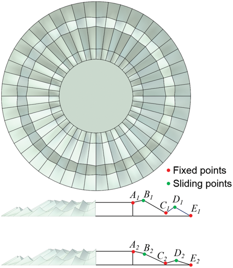
Figure 5: The geometry of the nest compared to the boundary lines (A1-E1) and the middle line (A2-E2) changing simultaneously
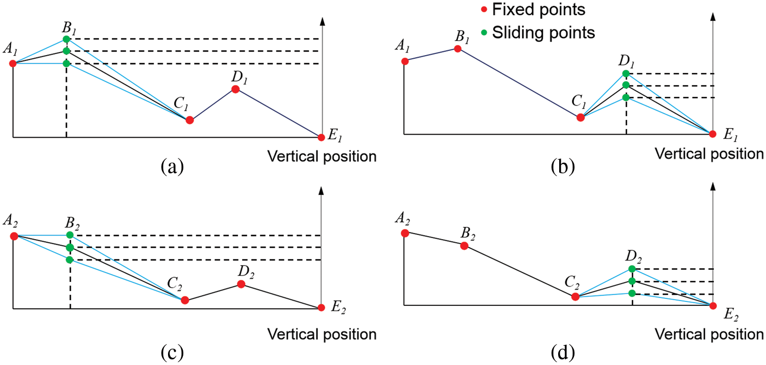
Figure 6: Changing style of the boundary lines (A1-E1) and middle line (A2-E2) of the unit channel: (a) the variation of B1; (b) the variation of D1; (c) the variation of B2; (d) the variation of D2
3 Fluid Behaviors of the Nest of Torquigener Albomaculosus
3.1 The Fluid Tunnel for Analyzing the Fluid Behaviors of the Nest
The commercial finite element software, HyperWorks (Version 2017, Altair Engineering, Inc., Troy, Michigan), was used to analyze the nest’s fluid behaviors. The finite element (FE) models of the nest were established in the CFD module of Hypermesh, a pre-processor of HyperWorks (Fig. 7). The fluid tunnel for analyzing the fluid behaviors of the nest was also established in the CFD module of Hypermesh with a length of 60 m, a width of 30 m, and a height of 30 m (Fig. 7a), which is big enough to send currents to the nest. The overall outer circle diameter of this nest is ensured as 2 m, and the central part of the nest is ensured as 0.8 m in diameter in the FE models of the nest. The fluid in the Virtual Wind Tunnel is set as water, and the flow speed of the water is set at 3 m/s. The Mach number is less than 1, the fluid type is incompressible, and HyperWorks’ CFD post-processor AcuSolve was used to analyze the fluid behavior of the nest. AcuSolve is based on the finite element (Galliakin Least-Squares) method and therefore has a fast and good convergence speed and achieves a high solution accuracy. It is a general-purpose CFD solver based on unstructured meshes, which is useful for some high-resolution outflow and inflow problems, thermal analysis, multi-physics field, and dynamic mesh problems. The turbulence model is chosen as laminar. The nest is divided by a triangular surface mesh, and the computational domain meshes with a tetrahedral mesh.

Figure 7: FE models of the nest and the virtual water tunnel
The governing equations of stable, incompressible fluids generally consist of the conservation equations of mass (continuity equation) and momentum conservation equation. The specific governing equation is as follows:
Mass conservation equation (continuity equation):
Momentum conservation equation (Reynolds-Averaged Navier-Stokes equation):
where ρ is density; μ is dynamic viscosity; u is velocity vector, m/s; u, v, and w are the components of velocity vector u in x, y, and z directions; Su, Sv, and Sw are generalized source terms for the momentum conservation equation.
The convergence of the mesh directly affects the accuracy of the calculated results, and it is essential to reduce the errors in CFD simulations [32]. Mesh delineation is very important for simulation calculations, and the type and accuracy of the mesh will directly affect the time and accuracy of the calculation. The geometry of the Torquigener albomaculosus nest is relatively regular but has a sharp structure, so we used a triangular surface mesh for delineation. In general, the higher the total number of cells in the mesh, the higher the accuracy and the easier it is to capture the detailed features of the object’s surface. However, the higher the number of meshes, the more computational time is required and the higher the computational configuration. In practical applications, it is necessary to strike a balance between computation time and accuracy. Therefore, we have to choose an appropriate number of meshes for the calculation.
Table 1 shows a relationship between the simulation results and the total number of mesh cells. Mesh 1 has a relatively large error compared to the other meshing strategies. The error between the remaining three groups is small. Considering the computer configuration as well as time consumption, Mesh 2 was chosen as the meshing strategy in this study.

3.2 The Results of the Fluid Behaviors with Univariate Parameters
Corresponding to Section 2.2, the fluid behaviors of the nest were investigated when the shapes of the boundary lines (A1-E1) in the channel unit changed. As shown in Fig. 8, the fluid in the virtual water tunnel comes from the left of the nest at a speed of 3 m/s, and the relative height of point B1 in the boundary lines (A1-E1) is 0.32 m compared to the fixed point E1. Fig. 8 also shows that the fluid speed of the left area in the nest is higher than the speed of the right area, and it can be found that the area of the highest speed is located in the θ ≈ 90° region, corresponding to the fluid flow direction.

Figure 8: The direction of the currents and flow velocity distribution of the model with a relative height of B1 is 0.32 m
While the shapes of the boundary lines (A1-E1) in the unit of the channel change, all the resulting fluid flow velocity images are given in Fig. 9. In Fig. 9, these models are arranged in the order of the vertical height of the point B1 from 0.32 to 0.43 m (0.32, 0.33, …, 0.43 m). They are divided into (a), (b), and (c) groups. Corresponding to Fig. 8, the red colors represent the high velocity, whereas the blue colors represent the low velocity. Interestingly, the velocity of group (a) is the fastest among the three groups, while the velocity of group (c) is the slowest. It can also be found that the areas of highest velocity in these models are in the θ ≈ 90° region, corresponding to the fluid flow direction. Moreover, the flow velocity distribution shows a high symmetry which directly demonstrates the accuracy of the simulations.
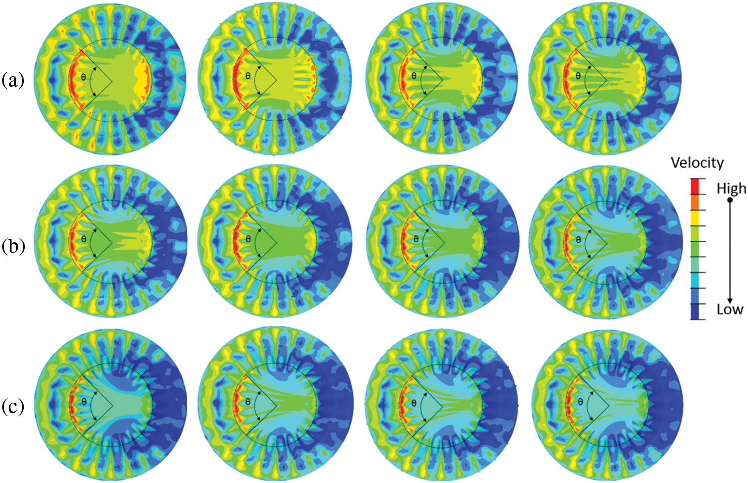
Figure 9: Flow velocity distribution in relation to the relative height of point B1 (from 0.32 to 0.43 m)
The living area of the nest is of significant importance for Torquigener albomaculosus, and the average velocity of the living area in the geometric model is calculated and compared in Fig. 10. The average velocity of the living area decreases when the relative height of the point B1 increases. Studying the fluid behaviors of the nest vs. the shapes of the boundary lines (A1-E1) in the unit of channel change provides a reference model for the following study. The model with the lowest average velocity of the living area is adopted as the initial model for the following analysis.

Figure 10: Flow velocity results of the living area in relation to the relative height of point B1
The fluid behaviors of the nest and the shapes of the middle line (A2-E2) in the channel unit change were also investigated. Fig. 11 illustrates the fluid flow velocity images when the shapes of the middle lines (A2-E2) in the channel unit change.
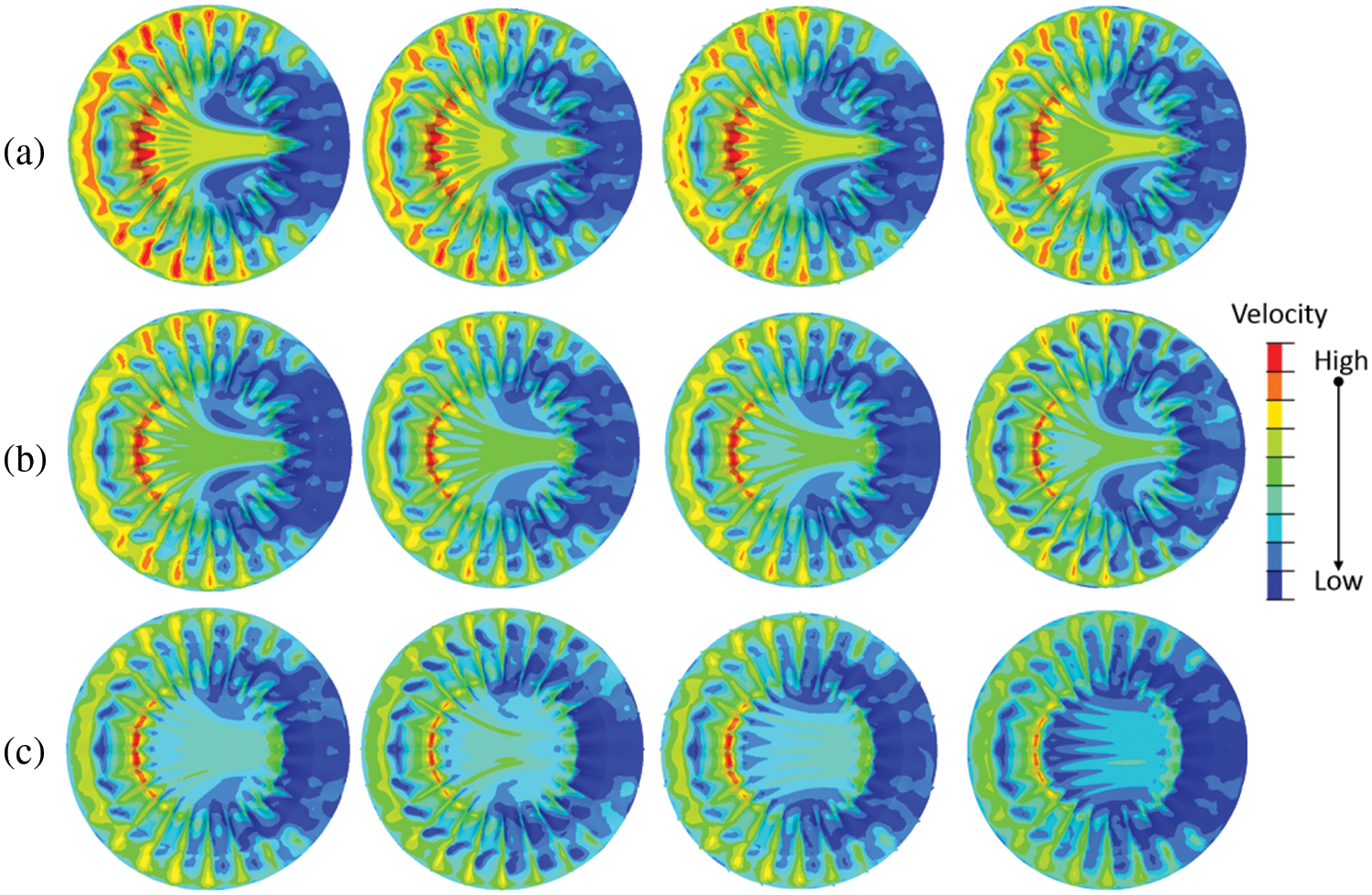
Figure 11: Flow velocity distribution in relation to the relative height of point B2 (from 0.20 to 0.31 m)
As depicted in Fig. 11, these models are arranged in the order of the vertical height of point B2 from 0.20 to 0.31 m and are also divided into (a), (b), and (c) groups. Corresponding to Figs. 8 and 9, the red colors represent the regions of high velocity, whereas the blue colors represent the regions of low velocity. The velocity of group (a) is the fastest among the three groups, and the velocity of group (c) is the slowest.
The velocity of the living area is calculated and compared in Fig. 12 when the relative height of point B2 changes from 0.20 to 0.31 m. It can be found that the average velocity of the living area increases with increasing the relative height from 0.20 to 0.29 m compared to the fixed point E2 in the middle line (A2-E2). In particular, the average velocity of the living area decreases drastically when the relative height increases to 0.30 m and further decreases at the relative height of 0.31 m.

Figure 12: Flow velocity results of the living area in relation to the relative height of point B2
3.3 The Designed Orthogonal Experiment for Fluid Analysis with Multivariate Parameters
Based on the above univariate fluid analysis, a group of orthogonal experiments were designed and conducted for multivariate fluid analysis in this section. As discussed in Section 2.2, the points B1 and D1 in the boundary lines (A1-E1) and points B2 and D2 middle line (A2-E2) of the unit channel are set as moving points, which can slide simultaneously in the vertical direction (Fig. 6). The height of the points B1, B2, D1, and D2 are given three different values in the orthogonal experiment for the fluid analysis as listed in Table 2.

As presented in Table 3, only 9 experiments are needed to replace 34 = 81 experiments in the designed orthogonal experiment. It is similar to the earlier detailed univariate fluid analysis. The fluid behaviors of the nest models from these 9 experiments are compared in Fig. 13. The average velocities of the living area from the 9 experiments are also listed in Table 3. Through calculating and comparing the ranges of the average velocities of Hi1, Hi2, Hi3 (Table 3), we find that the height of B1(H1) is the most significant factor whereas the height of D1 (H3) is the least significant factor. From the designed orthogonal experiment, the optimum solution for these four variate parameters can be obtained with the H31H21H33H41 combination. The designed optimum model with the H31H21H33H41 combination is also investigated. Compared to the 9 experimental results, the average velocity of the designed optimum model is the lowest, as shown in Fig. 14, with a value of 1.215 m/s, which proves the precision of the designed orthogonal experiment.
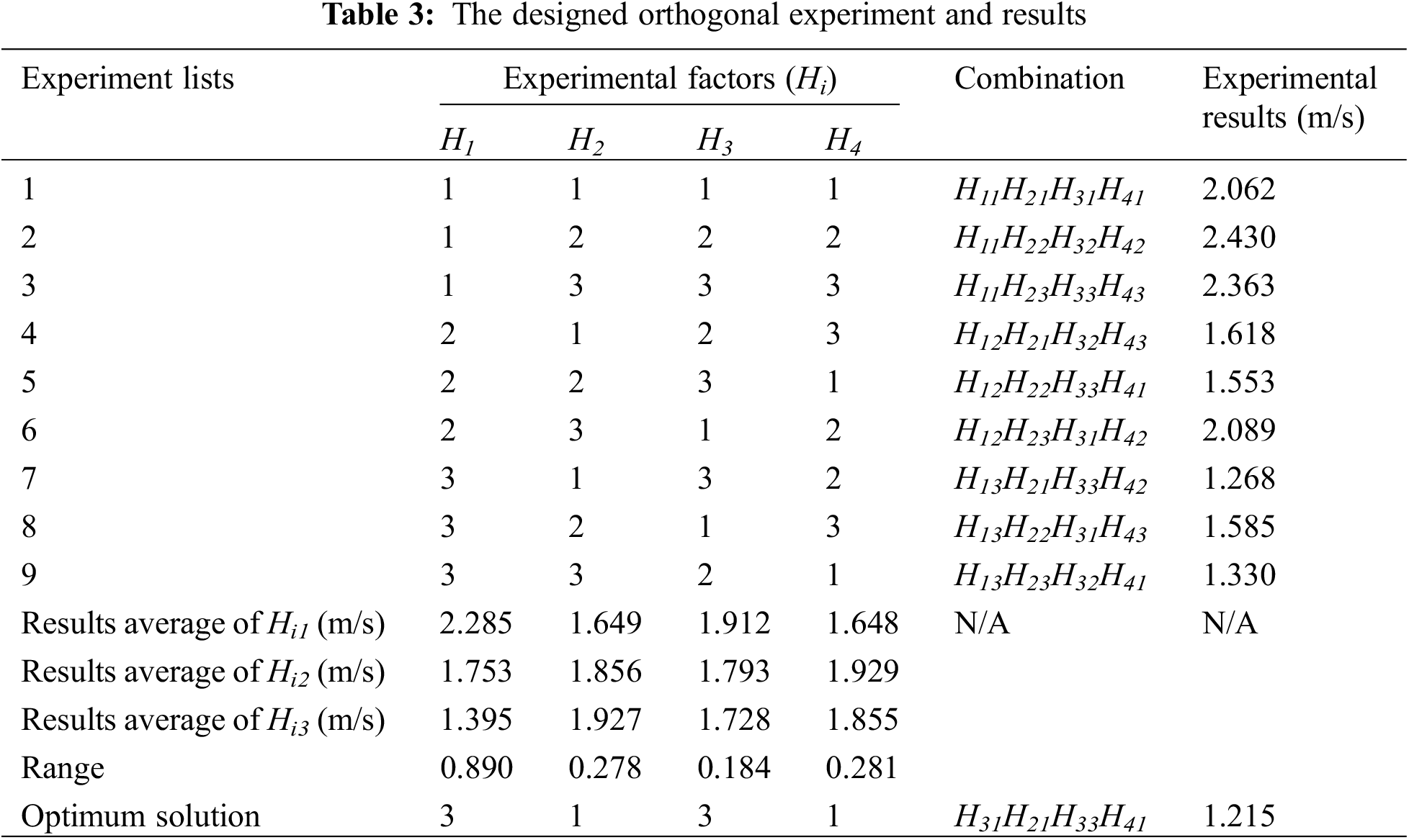
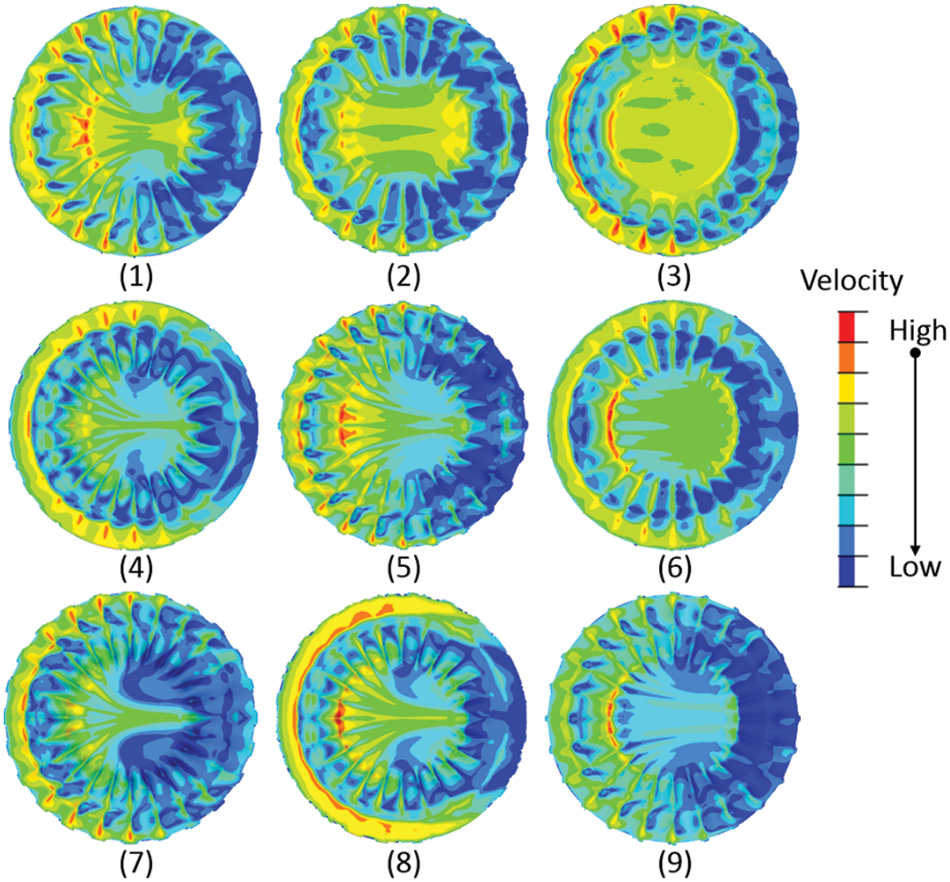
Figure 13: The fluid behaviors of the FE models in the orthogonal experiment
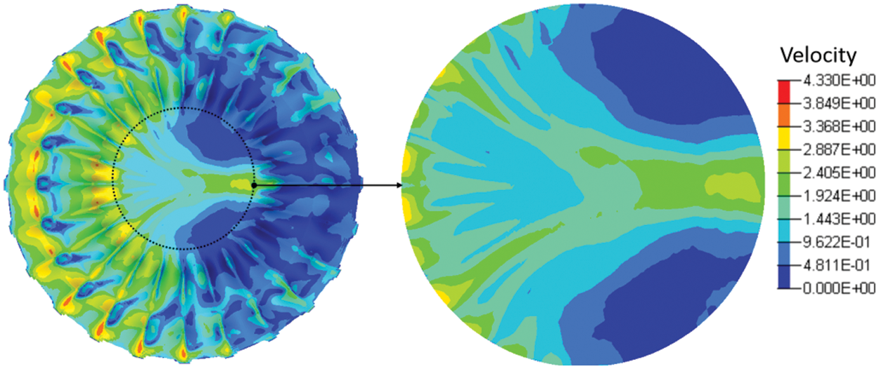
Figure 14: The fluid behaviors of the optimum model from the orthogonal experiment
In this paper, we constructed a geometric model of the nest that Torquigener albomaculosus builds. Three critical broken lines describe the channel unit of the nest. Firstly, we considered that the shapes of the boundary lines (A1-E1) and the middle line (A2-E2) change independently and respectively for fluid analysis. Then the shapes of the boundary lines (A1-E1) and the middle line (A2-E2) were conducted to change simultaneously for fluid analysis in this study.
(1) In the section of the univariate fluid analysis, it can be concluded that the average velocity of the living area decreases when the relative height of point B1 increases compared to the fixed point E1 in the boundary lines (A1-E1).
(2) In the univariate analysis, it is also obtained that the average velocity of the living area increases with the relative height increasing from 0.20 to 0.29 m compared to the fixed point E2 in the middle line (A2-E2). In particular, the average velocity of the living area is greatly decreased when the relative height has increased to 0.30 m, and further decreases at the relative height of 0.31 m.
(3) In the section on multivariate fluid analysis, a group of orthogonal experiments for fluid analysis were designed and conducted. It can be concluded that the relative height of B1 (H1) is the most significant factor, whereas the relative height of D1 (H3) is the least significant factor. According to the designed orthogonal experiments, the optimum solution for these four variate parameters can be obtained with the H31H21H33H41 combination, which shows the lowest average velocity (1.215 m/s).
In this paper, we revealed that the nests of Torquigener albomaculosus can effectively reduce the ocean current’s velocity in their living area. In future research, this structure can potentially be used in intercepting plastic waste moving with ocean currents. In addition, this structure has a further potential application as a buffer device against the incoming waves in offshore areas.
Acknowledgement: We thank Prof. Biczo for his linguistic assistance during theoreparation of this manuscript.
Funding Statement: This work is supported by the Henan Provincial Science and Technology Research Project (222102220068).
Author Contributions: Zhimin Zhao: Methodology, Writing-review & editing, Supervision. Shangbin Wang: Writing-original draft, Methodology, Conceptualization. Yuanhao Tie: Data curation. Ning Feng: Validation, Writing-review & editing, Supervision.
Conflicts of Interest: The authors declare that they have no conflicts of interest to report regarding the present study.
References
1. Ren, L., Liang, Y. (2014). Preliminary studies on the basic factors of bionics. Science China Technological Sciences, 57(3), 520–530. https://doi.org/10.1007/s11431-013-5449-1 [Google Scholar] [CrossRef]
2. Feng, N., Wang, S., Tie, Y., Liu, W., Zhao, Z. et al. (2022). Elastic deformability and zero poisson’s ratio within a novel structure inspired by the gardenia from nature. Mechanics of Advanced Materials and Structures, 1–13. https://doi.org/10.1080/15376494.2022.2135052 [Google Scholar] [CrossRef]
3. Kothari, N. B., Wohlgemuth, M. J., Moss, C. F. (2018). Adaptive sonar call timing supports target tracking in echolocating bats. Journal of Experimental Biology, 221(18), jeb176537. https://doi.org/10.1242/jeb.176537 [Google Scholar] [PubMed] [CrossRef]
4. Guney, M. S. (2016). Solar power and application methods. Renewable and Sustainable Energy Reviews, 57, 776–785. https://doi.org/10.1016/j.rser.2015.12.055 [Google Scholar] [CrossRef]
5. Hardy, G. S. (1983). Revision of Australian species of torquigener whitley (Tetraodontiformes: Tetraodontidaeand two new generic names for Australian puffer fishes. Journal of the Royal Society of New Zealand, 13(1–2), 1–48. https://doi.org/10.1080/03036758.1983.10415335 [Google Scholar] [CrossRef]
6. Matsuura, K. (2015). A new pufferfish of the genus torquigener that builds “mystery circles” on sandy bottoms in the Ryukyu Islands, Japan (Actinopterygii: Tetraodontiformes: Tetraodontidae). Ichthyological Research, 62(2), 207–212. https://doi.org/10.1007/s10228-014-0428-5 [Google Scholar] [CrossRef]
7. Wang, Z. Y., Yu, J. C., Zhang, A. Q., Wang, Y. X., Zhao, W. T. (2017). Parametric geometric model and hydrodynamic shape optimization of a flying-wing structure underwater glider. Chinese Ocean Engineering, 31, 709–715. https://doi.org/10.1007/s13344-017-0081-7 [Google Scholar] [CrossRef]
8. Mykhaskiv, O., Banović, M., Auriemma, S., Mohanamuraly, P., Walther, A. et al. (2018). NURBS-based and parametric-based shape optimization with differentiated CAD kernel. Computer-Aided Design and Applications, 15(6), 916–926. https://doi.org/10.1080/16864360.2018.1462881 [Google Scholar] [CrossRef]
9. Haftka, R. T., Villanueva, D., Chaudhuri, A. (2016). Parallel surrogate-assisted global optimization with expensive functions–A survey. Structural and Multidisciplinary Optimization, 54(1), 3–13. https://doi.org/10.1007/s00158-016-1432-3 [Google Scholar] [CrossRef]
10. Li, Z., Zheng, X. (2017). Review of design optimization methods for turbomachinery aerodynamics. Progress in Aerospace Sciences, 93, 1–23. https://doi.org/10.1016/j.paerosci.2017.05.003 [Google Scholar] [CrossRef]
11. Alkhatib, S. E., Mehboob, H., Tarlochan, F. (2019). Finite element analysis of porous titanium alloy Hip stem to evaluate the biomechanical performance during walking and stair climbing. Journal of Bionic Engineering, 16(6), 1103–1115. https://doi.org/10.1007/s42235-019-0122-4 [Google Scholar] [CrossRef]
12. Li, Y. C., Pan, D. Y., Ma, Z., Zhao, Q. S. (2019). Aspect ratio effect of a pair of flapping wings on the propulsion of a bionic autonomous underwater glider. Journal of Bionic Engineering, 16, 145–153. https://doi.org/10.1007/s42235-019-0013-8 [Google Scholar] [CrossRef]
13. Mariotti, A., Buresti, G., Salvetti, M. V. (2014). Control of the turbulent flow in a plane diffuser through optimized contoured cavities. European Journal of Mechanics-B/Fluids, 48, 254–265. https://doi.org/10.1016/j.euromechflu.2014.04.009 [Google Scholar] [CrossRef]
14. Daniels, S. J., Rahat, A. A. M., Tabor, G. R., Fieldsend, J. E., Everson, R. M. (2019). Automated shape optimisation of a plane asymmetric diffuser using combined computational fluid dynamic simulations and multi-objective Bayesian methodology. International Journal of Computational Fluid Dynamics, 33, 256–271. https://doi.org/10.1080/10618562.2019.1683165 [Google Scholar] [CrossRef]
15. González Niño, C., Kapur, N., King, M. F., de Boer, G., Blacker, A. J. et al. (2019). Computational fluid dynamic enabled design optimisation of miniaturised continuous oscillatory baffled reactors in chemical processing. International Journal of Computational Fluid Dynamics, 33, 317–331. https://doi.org/10.1080/10618562.2019.1683169 [Google Scholar] [CrossRef]
16. Sachs, G., Moelyadi, M. A. (2010). CFD based determination of aerodynamic effects on birds with extremely large dihedral. Journal of Bionic Engineering, 7(1), 95–101. https://doi.org/10.1016/S1672-6529(09)60191-8 [Google Scholar] [CrossRef]
17. Meng, X., Liu, Y., Sun, M. (2017). Aerodynamics of ascending flight in fruit flies. Journal of Bionic Engineering, 14(1), 75–87. https://doi.org/10.1016/S1672-6529(16)60379-7 [Google Scholar] [CrossRef]
18. Dong, H., Wu, Z., Tan, M., Yu, J. (2020). Hydrodynamic analysis and verification of an innovative whale shark-like underwater glider. Journal of Bionic Engineering, 17(1), 123–133. https://doi.org/10.1007/s42235-020-0010-y [Google Scholar] [CrossRef]
19. Du, X., Liu, M., Sun, Y. (2022). Optimization of the internal circulating fluidized bed using computational fluid dynamics technology. Fluid Dynamics & Materials Processing, 18, 303–312. https://doi.org/10.32604/fdmp.2022.016242 [Google Scholar] [CrossRef]
20. Cheng, H., Du, G., Zhang, M., Wang, K., Bai, W. (2020). Determination of the circulation for a large-scale wind turbine blade using computational fluid dynamics. Fluid Dynamics & Materials Processing, 16, 685–698. https://doi.org/10.32604/fdmp.2020.09673 [Google Scholar] [CrossRef]
21. Salahuddin, T., Javed, A., Khan, M., Awais, M., Bangali, H. (2022). The impact of soret and dufour on permeable flow analysis of carreau fluid near thermally radiated cylinder. International Communications in Heat and Mass Transfer, 138, 106378. https://doi.org/10.1016/j.icheatmasstransfer.2022.106378 [Google Scholar] [CrossRef]
22. Feng, N., Liu, L., Liu, Y., Leng, J. (2015). A bio-inspired, active morphing skin for camber morphing structures. Smart Materials and Structures, 24(3), 035023. https://doi.org/10.1088/0964-1726/24/3/035023 [Google Scholar] [CrossRef]
23. Xiang, J., Du, J. (2017). Energy absorption characteristics of bio-inspired honeycomb structure under axial impact loading. Materials Science and Engineering: A, 696, 283–289. https://doi.org/10.1016/j.msea.2017.04.044 [Google Scholar] [CrossRef]
24. Zhang, Y., Xu, X., Wang, J., Chen, T., Wang, C. H. (2018). Crushing analysis for novel bio-inspired hierarchical circular structures subjected to axial load. International Journal of Mechanical Sciences, 140, 407–431. https://doi.org/10.1016/j.ijmecsci.2018.03.015 [Google Scholar] [CrossRef]
25. Ko, K., Jin, S., Lee, S. E., Lee, I., Hong, J. W. (2019). Bio-inspired bimaterial composites patterned using three-dimensional printing. Composites Part B: Engineering, 165, 594–603. https://doi.org/10.1016/j.compositesb.2019.02.008 [Google Scholar] [CrossRef]
26. Salahuddin, T., Bashir, A. M., Khan, M., Al Alwan, B., Almesfer, M. (2022). Hybrid nanofluid analysis for a class of alumina particles. Chinese Journal of Physics, 77, 2550–2560. https://doi.org/10.1016/j.cjph.2021.11.012 [Google Scholar] [CrossRef]
27. Salahuddin, T., Khan, M. H. U., Khan, M., Al Alwan, B., Amari, A. (2022). An analysis on the flow behavior of MHD nanofluid with heat generation. Fuel, 311, 122548. https://doi.org/10.1016/j.fuel.2021.122548 [Google Scholar] [CrossRef]
28. Hu, J., Huang, X., Jin, Y. (2021). A CFD study on a biomimetic flexible two-body system. Fluid Dynamics & Materials Processing, 17, 597–614. https://doi.org/10.32604/fdmp.2021.014249 [Google Scholar] [CrossRef]
29. Chen, L., Wang, Y., Qi, C., Tang, Z., Tian, Z. (2022). A review of methods based on nanofluids and biomimetic structures for the optimization of heat transfer in electronic devices. Fluid Dynamics & Materials Processing, 18, 1205–1227. https://doi.org/10.32604/fdmp.2022.021200 [Google Scholar] [CrossRef]
30. Yuan, Y., Yu, X., Yang, X., Xiao, Y., Xiang, B. et al. (2017). Bionic building energy efficiency and bionic green architecture: A review. Renewable and Sustainable Energy Reviews, 74, 771–787. https://doi.org/10.1016/j.rser.2017.03.004 [Google Scholar] [CrossRef]
31. Meng, X. G., Sun, M. (2015). Aerodynamics and vortical structures in hovering fruitflies. Physics of Fluids, 27, 031901. https://doi.org/10.1063/1.4914042 [Google Scholar] [CrossRef]
32. Celik, I. B., Ghia, U., Roache, P. J., Freitas, C. J. (2008). Procedure for estimation and reporting of uncertainty due to discretization in CFD applications. Journal of Fluids Engineering, 130(7). https://doi.org/10.1115/1.2960953 [Google Scholar] [CrossRef]
Cite This Article
 Copyright © 2023 The Author(s). Published by Tech Science Press.
This work is licensed under a Creative Commons Attribution 4.0 International License , which permits unrestricted use, distribution, and reproduction in any medium, provided the original work is properly cited.
 Downloads
 Citation Tools