
 Submit a Paper
 Propose a Special lssue
 Open Access
ARTICLE

Research on the Corrosion of J55 Steel Due to Oxygen-Reducing Air Flooding in Low-Permeability Reservoirs
1
School of Petroleum Engineering, Yangtze University, Wuhan, 430100, China
2
Beijing Huacheng Hengye Petroleum Technology Development Limited Company, Beijing, 101499, China
3
Petroleum Engineering Technology Research Institute of North China Oil & Gas Company, Zhengzhou, 450006, China
* Corresponding Author: Fajian Nie. Email:
Fluid Dynamics & Materials Processing 2023, 19(7), 1925-1937. https://doi.org/10.32604/fdmp.2023.025966
Received 08 August 2022; Accepted 25 October 2022; Issue published 08 March 2023
 View Full Text
 Download PDF
Abstract
Oxygen-reducing air flooding is a low-permeability reservoir recovery technology with safety and low-cost advantages. However, in the process of air injection and drive, carbon in the air is oxidized through the crude oil reservoir to generate CO2, and this can cause serious corrosion in the recovery well. In this study, experiments on the corrosion of J55 tubular steel in a fluid environment with coexisting O2 and CO2 in an autoclave are presented. In particular, a weight loss method and a 3D morphometer were used to determine the average and the local corrosion rate. The corrosion surface morphology and composition were also measured by means of scanning electron microscopy (SEM) and an X-ray diffractometer (XRD). The corrosion pattern and morphological characteristics of J55 steel were analyzed in the O2/CO2 environment for different degrees of oxygen-reduction. As made evident by the experimental results, the corrosion products were mainly ferrous carbonate and iron oxide. In general, air injection increases the degree of oxygen reduction, from oxygen corrosion characteristics to CO2 corrosion-based characteristics. As a result, the corrosion product film becomes denser, and the corrosion rate is lower.Keywords
Oxygen-reduced air flooding is a low-risk and low-cost tertiary oil recovery technology that has recently emerged. The mechanism of air flooding is to make the oxygen in the air react with the crude oil by low-temperature oxidation. It generates CO and CO2 while regulating the viscosity of crude oil and then combines with N2 and light hydrocarbon components to form flue gas to repel crude oil [1,2]. For low-permeability reservoirs, if un-reduced-oxygen air is injected directly for oil flooding, the oxygen in the injected gas does not enter the reservoir in time, leading to a high oxygen concentration in the production wells, which may heighten the risk of explosion [3,4]. Therefore, the method of reducing the oxygen content in the air to a pre-determined level by air separation equipment before injection has received wide attention. Oil fields such as Changqing, Qinghai, and North China have started to apply oxygen-reducing air flooding to the extraction of low-permeability oil fields.
In the process of air injection and oil flooding, the oxygen in the air reacts with the reservoir crude oil to produce CO2, and the O2 and CO2 together cause corrosion to the tubular column in the extraction section [5–7], resulting in serious deterioration of the tubular column in the extraction well. It affects the safety of oil well extraction and causes huge economic losses. The current research on J55 steel mainly involves corrosion in a single gas (O2 or CO2) environment. The O2 and/or CO2 in the air or neutral solution, and the mechanism of electrochemical corrosion are shown in Fig. 1. Zhu concluded that in an environment of O2 and CO2 coexistence, the corrosion product film on the material surface does not form a dense protective layer, and the synergistic corrosion effect of O2 and CO2 is stronger than the single corrosion effect of O2 or CO2 only [8]. Zhang et al. [9] argued that the corrosion products produced under the synergistic corrosion of O2 and CO2 have less adhesion to the metal surface, are easy to fall off, and the corrosion rate is significantly greater than the corrosion rate of O2 and CO2 under a single component. At the same time, the main product of the corrosion reaction is produced under high-temperature conditions. FeCO3 is more stable and has good film-forming properties. And oxidation generated by Fe2O3 and FeOOH protection is weak [10–12].
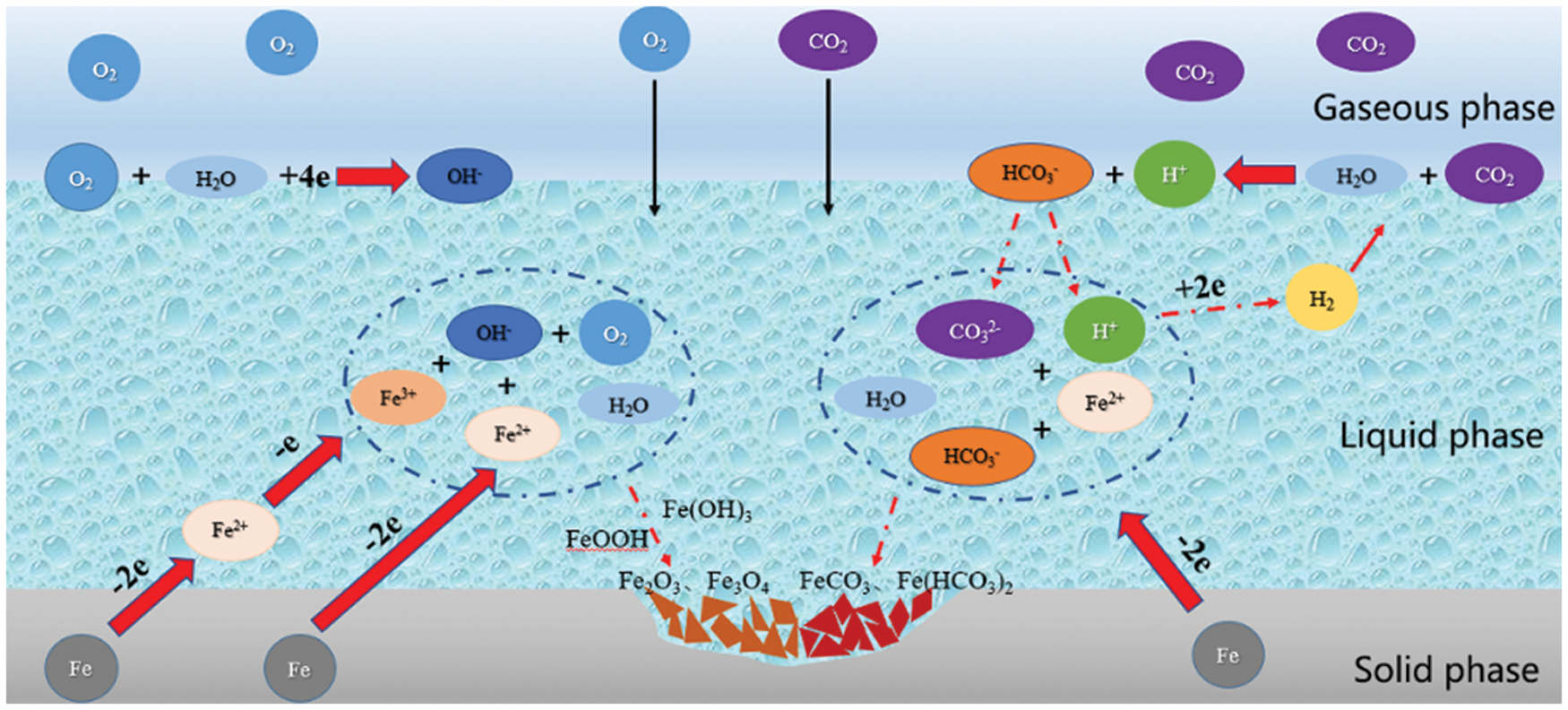
Figure 1: Schematic diagram of the electrochemical corrosion process of O2 and CO2
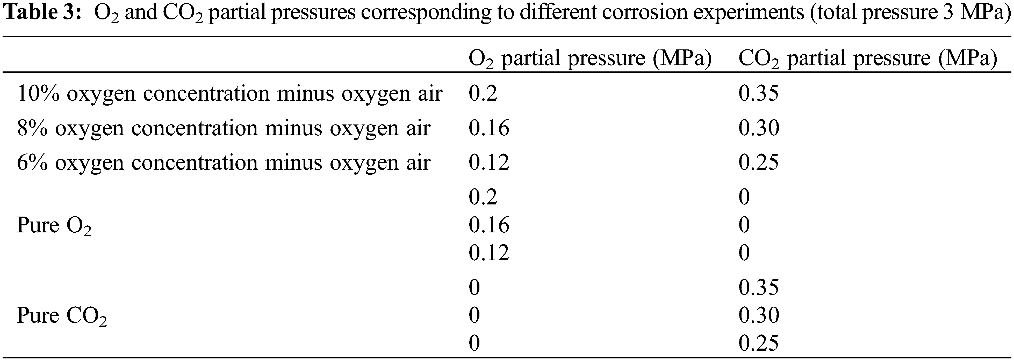
As shown in Fig. 2, the oxygen concentration of oxygen-reduced air is less costly when it is between 6% and 10%. The cost difference between 6% and 10% is not significant. In this paper, three groups of oxygen-reduced air with 6%, 8% and 10% oxygen concentrations were selected. The O2 and CO2 partial pressures after injection into the corresponding output wells through reservoir oxidation were simulated. Corrosion experiments were conducted on J55 steel in a hot fluid environment. Corrosion experiments of J55 steel were conducted in a single O2 and CO2 environment for control.
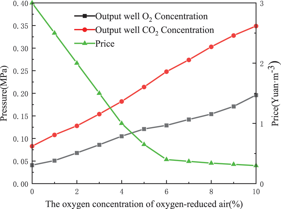
Figure 2: Price of oxygen-reduced air production with different oxygen content and O2 and CO2 partial pressure in the output well after injection [2]
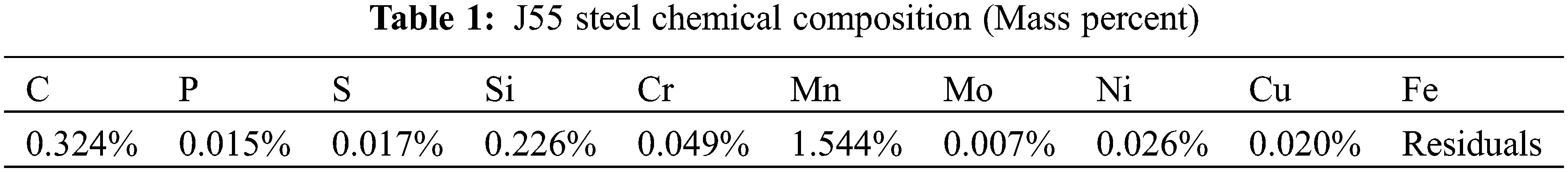
Corrosion pegs: J55 steel, size 72.4 mm × 21.5 mm × 2.2 mm. The chemical composition of the J55 steel used is shown in Table 1.
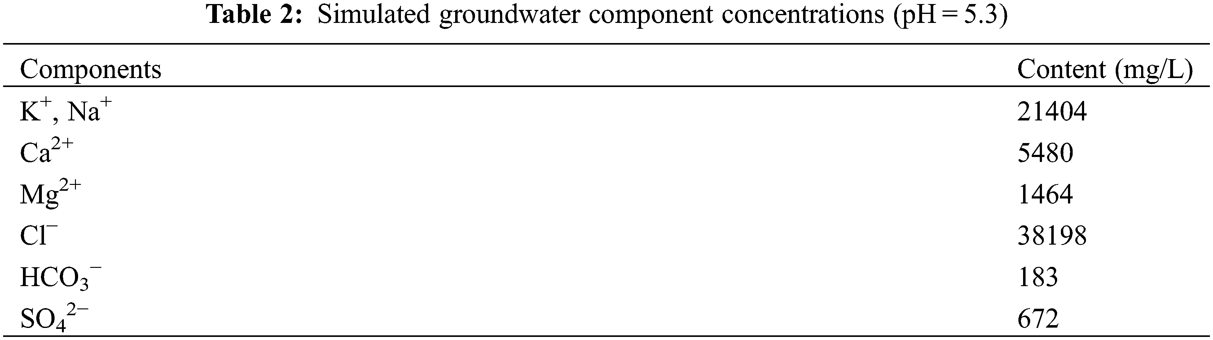
Corrosion solution: simulated groundwater. The simulated formation water used in this experiment was formulated with reference to the field formation water components, and the component concentrations of the simulated formation water are presented in Tables 2 and 3.
The equipment used in this experiment are a high-temperature autoclave (Hastelloy high-temperature and high-pressure corrosion system: volume 10 L, maximum working pressure 10 MPa, maximum working temperature 240°C); HH-8 digital display constant temperature water bath; JJ-1 magnetic heating stirrer; JJ223BC electronic precision balance; 5W-W electric, desktop, regular temperature drying oven, JSM-6390 scanning electron microscope; XRD-6000 diffractometer; CoutourGT-X three-dimensional morphology instrument.
Temperature: 60°C, speed: 150 r/min, corrosion time: 7 days.
Each group of experiments consisted of three parallel specimens (I, II, III). Specimen I is used to test the surface morphology and corrosion product composition. Specimen II tests the three-dimensional morphology and local corrosion rate after the film removal. Specimens II, III push the uniform corrosion rate after removing film and takes the average value. Experiment-specific operation steps [13–17] are as follows:
(1) Firstly, the pegs were polished and sanded to the same degree of finish on their surfaces, corners, and holes. Then rinsed with deionized water and put into acetone to degrease. Then soaked in anhydrous ethanol to further degrease and dehydrate. Finally, the pegs were dried, measured, and weighed.
(2) Fig. 3 shows the schematic diagram of the high-temperature and high-pressure corrosion experimental device.
(3) Set the speed of the reactor, raise the temperature to the preset temperature (60°C), and wait for the temperature to stabilize. Pass in N2 to replenish the pressure in the kettle to 3 MPa. Start the corrosion experiment, remove the hanging piece after seven days, and observe and record the surface condition before treatment.
(4) Specimen I was placed in a drying dish after rinsing, dehydration, and cold air drying, and then the microscopic morphology of corrosion products was observed by scanning electron microscopy. Next, the film composition of corrosion products was analyzed by XRD diffractometer.
(5) Specimens II and III, another set of empty pegs, were put into the ultrasonic cleaning machine containing hydrochloric acid washing solution to remove corrosion products. The ratios of the pickling solution are as follows: 35 mL hydrochloric acid (37% concentration). 315 mL pure water and 3.15 g hexamethyltetramine. The cleaning temperature is 30°C, with a cleaning time of 15 min. After the completion of acid cleaning, the hanging piece was subjected to anhydrous ethanol dehydration, and then put in the drying oven for one h. At the end of oven-drying, the pegs were taken out, weighed, and the average corrosion rate calculated as shown below:
where: V is the uniform corrosion rate, mm/a; m1 is the mass of the hanging piece before cleaning g; m2 is the mass of the hanging piece after cleaning, g; m3 is the mass of the blank hanging piece before cleaning, g; m4 is the mass of the blank hanging piece after cleaning, g; S is the surface area of the test piece, cm2; t is the the experimental time, h; ρ is the material density of the hanging piece, g/cm3.
(6) After weighing specimen II, the three-dimensional morphology instrument was used to observe the three-dimensional morphology of the hanging sheet after the removal of corrosion products, and the local corrosion rate was calculated as follows:
where:
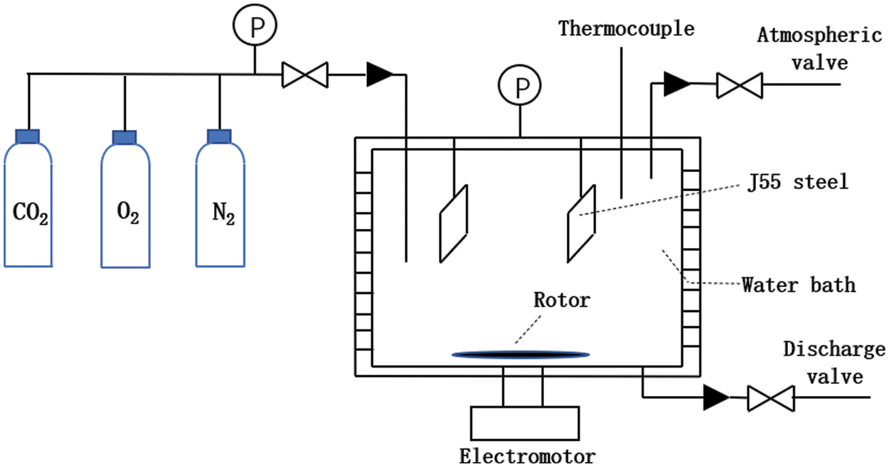
Figure 3: High-temperature and high-pressure dynamic hanging corrosion experimental device schematic diagram
3 Experimental Results and Discussion
3.1 Corrosion Morphological Characteristics
Fig. 4 shows the corrosion morphology of J55 steel under the fluid environment of a single O2/CO2 corrosive medium, respectively. As seen in Fig. 4a, the corrosion products on the surface of the specimen in a single O2 environment (O2 partial pressure of 0.2 MPa) are dark brown. The surface of the peg is distributed with uneven pitting, and its microscopic morphology shows obvious cracks and pores. Fig. 4b shows that the specimen surface corrosion layer is thin and relatively flat in a single CO2 environment (CO2 partial pressure of 0.35 MPa). SEM observations show that the corrosion product is a dense accumulation of blocks. Corrosion product film has a certain protective effect on the metal matrix.
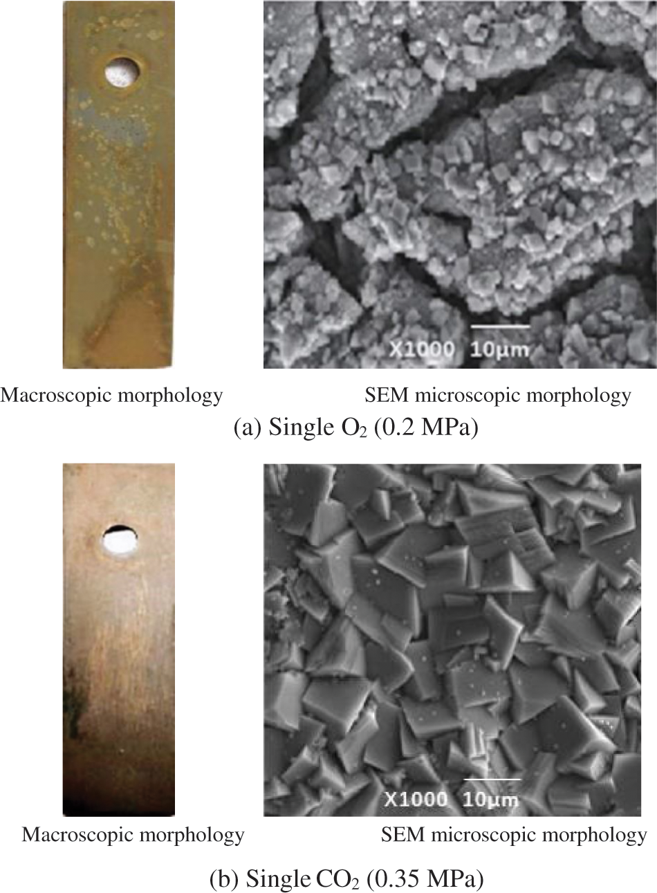
Figure 4: Corrosion profile of J55 steel in a single O2/CO2 environment
Fig. 5 shows the macroscopic morphology and microscopic morphology of corrosion of J55 steel under three groups of O2 and CO2 mixed gas environments with different partial pressures. It is observed that there are corrosion products stacked on the material surface in all groups of environments. But in different O2/CO2 partial pressure environments, the type of corrosion layer and degree of corrosion differ. As shown in Fig. 5a, the corrosion products are thicker and looser in the O2 partial pressure of 0. 2 MPa and CO2 partial pressure of 0.35 Mpa than what was seen in the single O2 (O2 partial pressure of 0.2 MPa) environment. Cracks and pores are more obvious. There is an obvious corrosion layer-off phenomenon in the microscopic morphology of the point pit at the attachment of fine white grains. SEM observations showed that the cracks have a large leaf-like corrosion material generated. In O2 partial pressure of 0.16 MPa, and CO2 partial pressure of 0.3 MPa, the corrosion layer is thin, and the corrosion layer appears dark brown. This indicates that the degree of corrosion of the specimen is slowed down. Through the microscopic morphology, it was observed that the corrosion layer still has some voids, while the inner layer of blade-like corrosion products is denser. In the O2 partial pressure of 0.12 MPa and CO2 partial pressure of 0.25 MPa, the corrosion layer is flatter and thicker, with no obvious local corrosion pits. SEM observations show that the corrosion products on the metal surface were a dense accumulation of blocks, indicating that the characteristic CO2 corrosion dominated [18–20]. The above morphological features of corrosion indicate that the decline of J55 steel under the synergistic effect of O2 and CO2 is more serious than in single O2 or CO2 environment. The corrosion situation is significantly reduced by the injection of increasingly oxygen-reduced air.
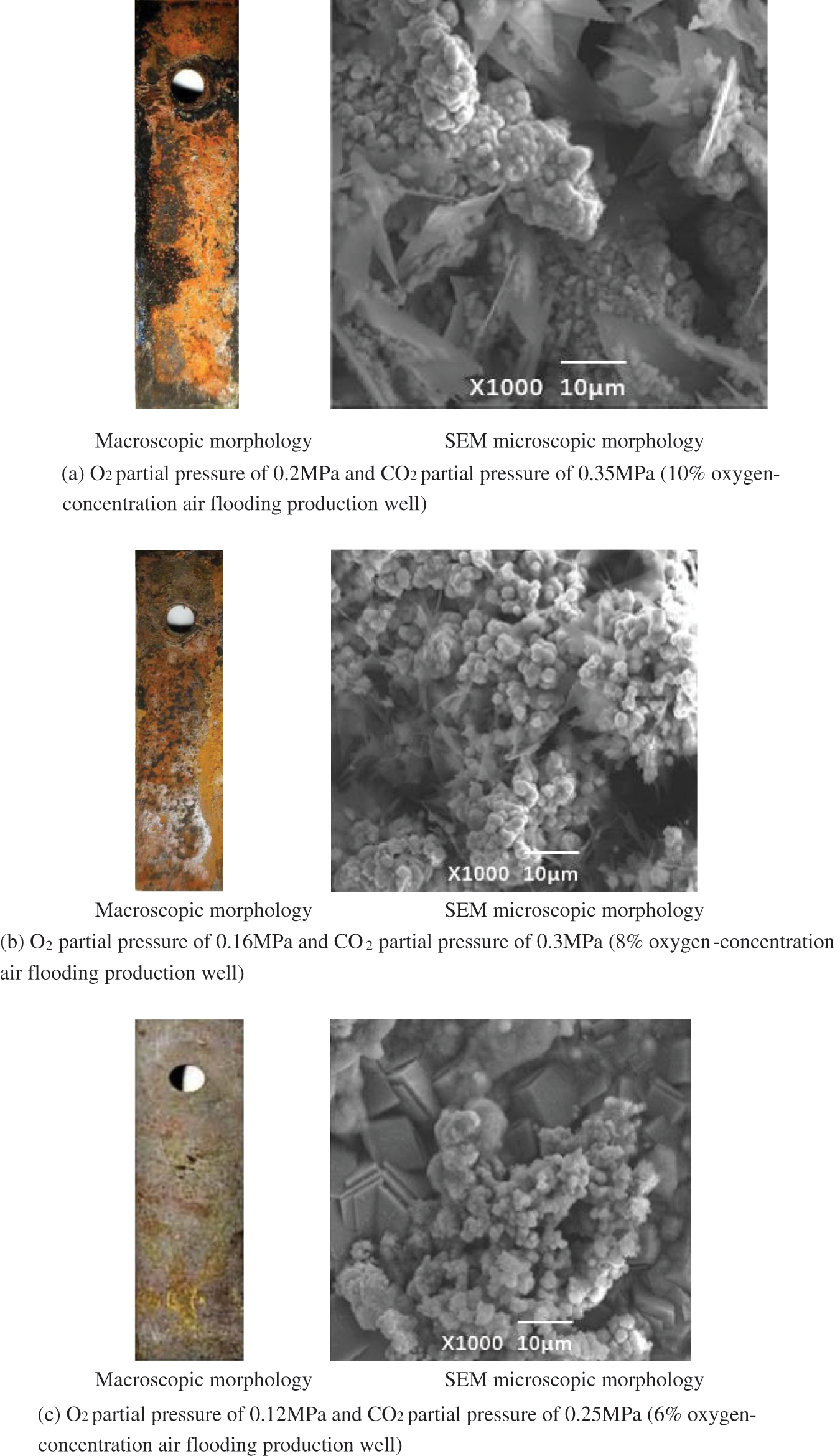
Figure 5: Macroscopic appearance of J55 steel corrosion under different partial pressure O2/CO2 coexistence environment
3.2 Analysis of the Composition of Corrosion Product Films
From Fig. 6a, the corrosion product film of J55 steel in a single O2 environment (O2 partial pressure of 0.2 MPa) was mainly composed of iron oxide. It showed irregular distribution characteristics on the metal surface. And a small amount of Fe elements was detected on the corrosion product film surface. It indicates that the morphology of the corrosion product film in some areas of the single O2 environment is very thin, leading to the detection of the inner metal composition by X-ray breakdown of the corrosion product film [21]. From Fig. 6b, in a single CO2 environment (CO2 partial pressure of 0.35 MPa), the corrosion product film of J55 steel is mainly composed of ferrous carbonate and a small amount of Fe(HCO3)2.
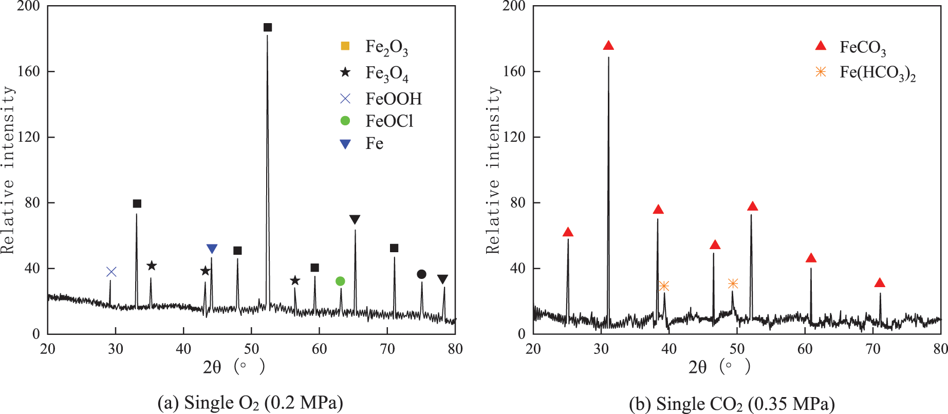
Figure 6: XRD pattern of corrosion products of J55 steel in a single O2/CO2 environment
In the coexistence of O2 and CO2, the main products of corrosion are FeCO3 and Fe oxides (Fe2O3 is dominant), as determined from the XRD pattern analysis. As shown in Fig. 7a, the supersaturation of Fe2+ and CO32− in the solution is larger when the partial pressure of O2 is 0. 2 MPa and the partial pressure of CO2 is 0.35 MPa. The grain nucleation rate is higher this time, and the FeCO3 grains formed are relatively small. The white grains generated in Fig. 5a are FeCO3, and trace amounts of Fe3O4 and FeOCl are also generated due to the high concentration of dissolved oxygen in the solution. However, the peak value of FeCO3 increases with the decrease of CO2 concentration, and Fe3O4 is no longer produced. As shown in Fig. 7c, the peak value of FeCO3 tends to be constant when the partial pressure of O2 is 0.12 MPa, and the partial pressure of CO2 is 0.25 MPa, while the amount of Fe2O3 production decreases significantly. When the oxygen concentration and CO2 concentration are reduced simultaneously, the amount of FeCO3 on the steel surface increases. The FeCO3 corrosion product film is denser, which can alleviate the oxygen-induced corrosion effect on the J55 steel sheet [22]. According to XRD analysis, the main corrosion reaction processes of J55 steel in different corrosive media are as follows [23–28].
(1) Reaction under the action of CO2
Anodic reaction:
Cathodic reaction:
The total reaction equation is:
(2) Reaction under the action of O2:
(3) Reaction under the joint action of O2 and CO2:
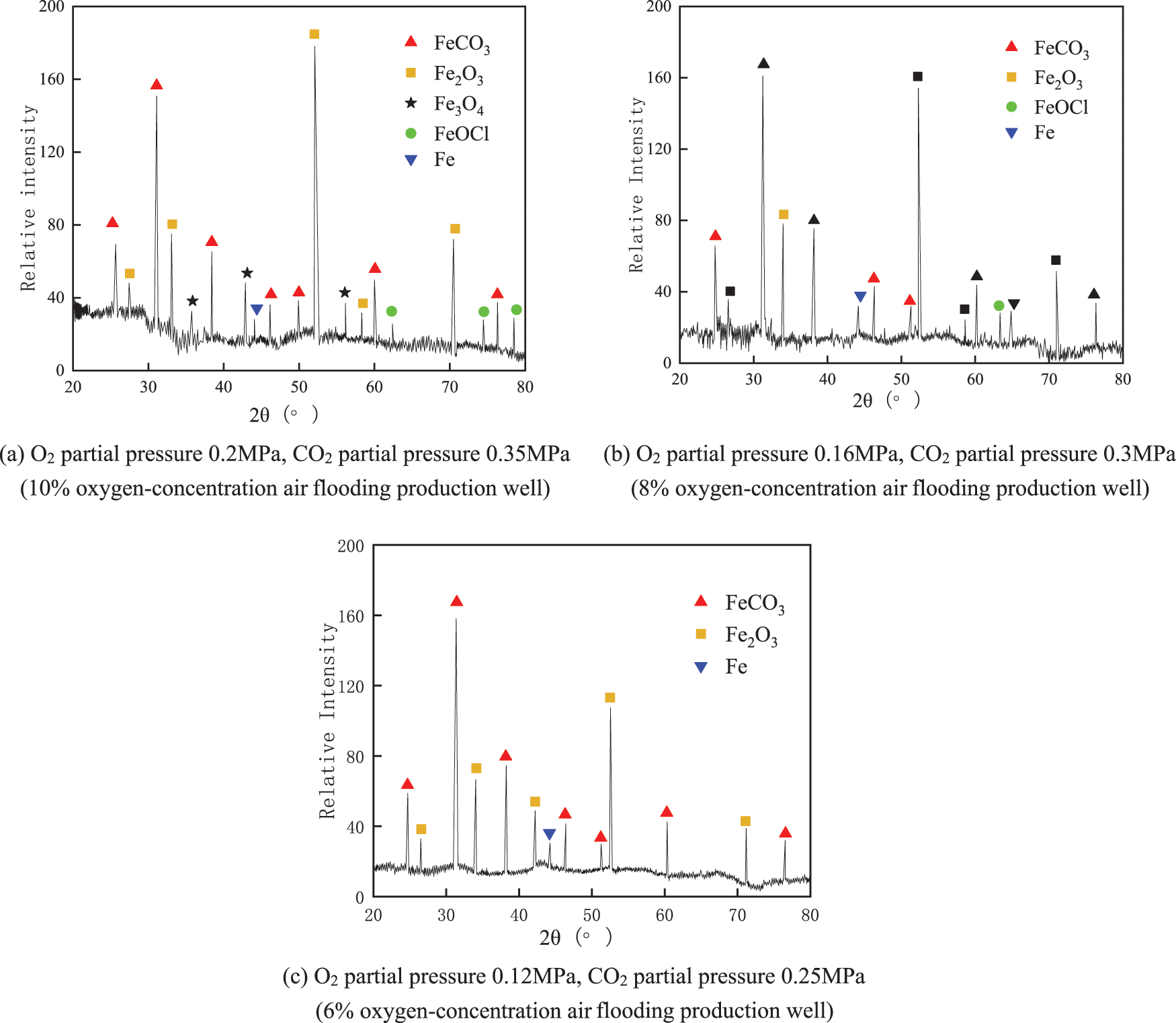
Figure 7: XRD pattern of corrosion products of J55 steel under the coexistence of O2 and CO2
The difference in corrosion product film composition can be obtained by comparing the single O2/CO2 environment and the coexistence of O2 and CO2. The corrosion products under a single O2 environment are dominated by iron oxides (Fe2O3, Fe3O4). O2 and CO2 coexistence environments both exist. Combined with the corrosion morphology analysis, O2 and CO2 synergistic effect of oxygen corrosion and CO2 corrosion characteristics. When the O2 partial pressure increases, iron oxide production increases. But the corrosion product film is unstable and easy to peel off from the material’s surface. J55 steel constantly undergoes CO2 corrosion damage to the material. When J55 steel was in a lower oxygen concentration and CO2 concentration, corrosion began to tend to exhibit characteristic CO2 corrosion. And because FeCO3 is more stable, it can effectively prevent dissolved oxygen penetration into the corrosion layer and aggravating corrosion.
3.3 Three-Dimensional Morphological Analysis after Removal of Corrosion Products
Fig. 8 shows the three-dimensional surface morphology of the hanging sheet under different corrosive media after the removal of corrosion products. Figs. 8a and 8c show that the J55 steel in a single O2 environment and O2/CO2 coexistent environment both show different degrees of pitting corrosion. The pitting corrosion of J55 steel in the O2/CO2 coexistence environment is relatively more serious. There are more pitting areas and a greater degree of corrosion. The J55 steel in the single O2 environment also had more pitting areas and the second highest degree of pitting corrosion. Fig. 8b shows that the corrosion area under a single CO2 environment is larger, but the overall corrosion depth is smaller, indicating uniform corrosion.
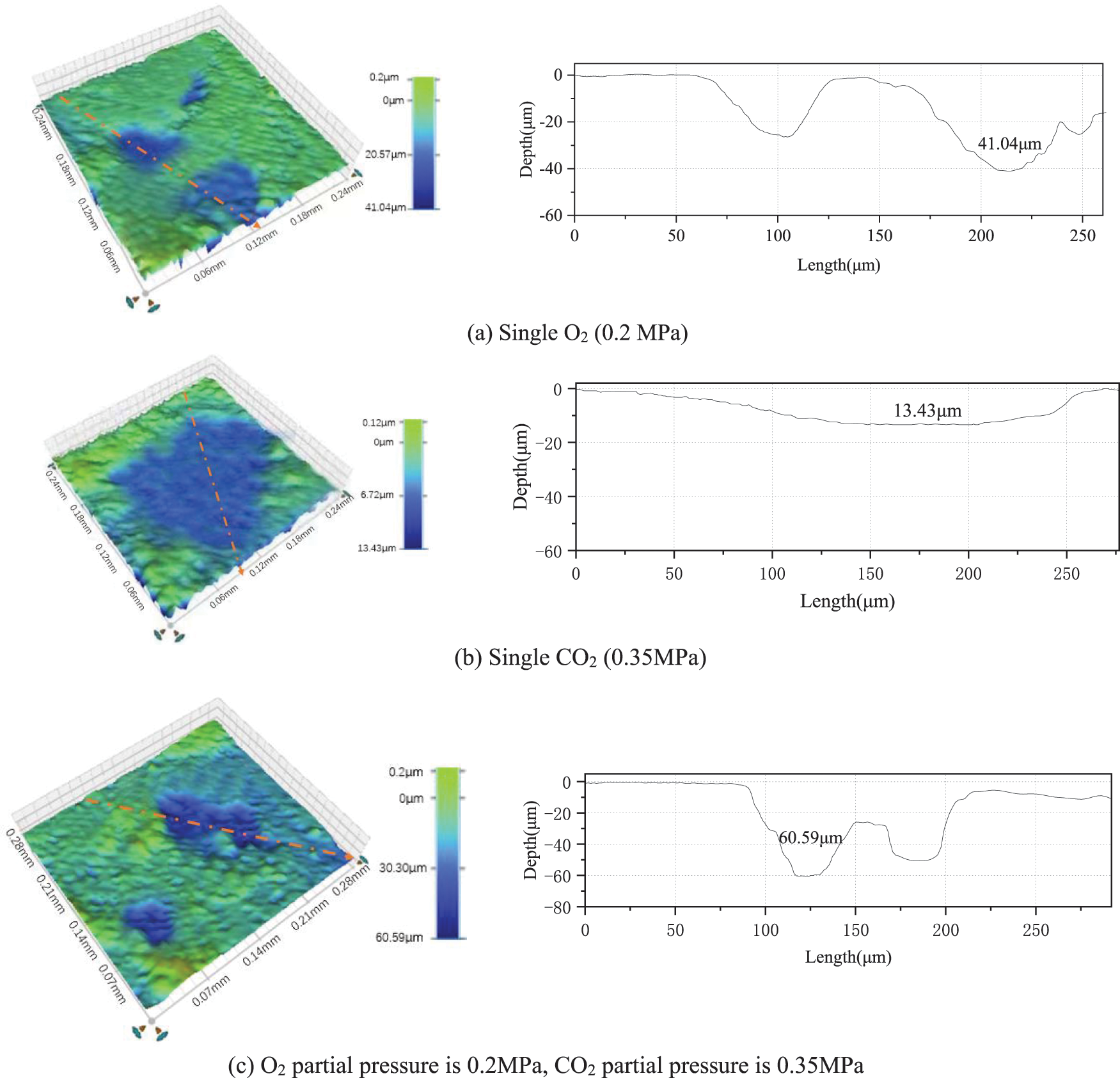
Figure 8: J55 steel in different corrosive media three-dimensional morphology and cross-sectional corrosion depth
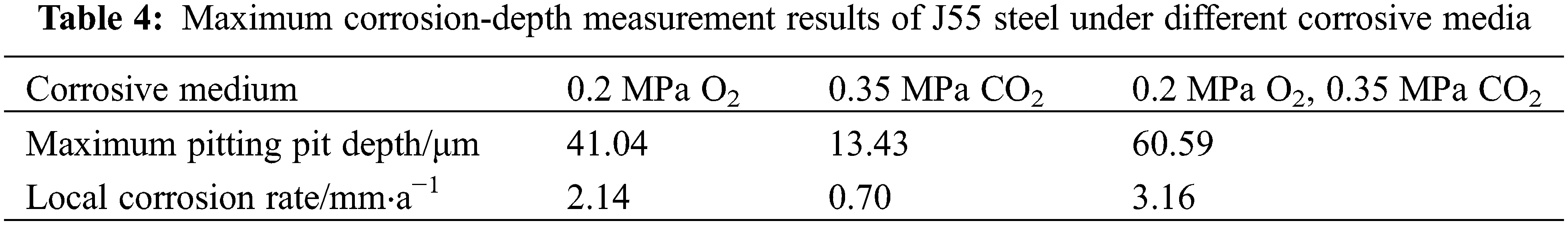
The local corrosion pit depth and local corrosion rate of steel under the three corrosive media are shown in Table 4. The local corrosion rate under single O2, single CO2, and O2/CO2 coexistence environment are 2.14 mm/a, 0.70 mm/a, and 3.16 mm/a, respectively. The local corrosion rate under the O2/CO2 coexistence environment exceeds the sum of the local corrosion rate under a single O2 environment and a single CO2 environment. It means that when O2 and CO2 coexist, CO2 accumulates on the surface of J55 steel, where pitting corrosion occurs, to further increase the depth of pitting corrosion. The presence of CO2 aggravates the pitting corrosion of J55 steel.
3.4 Analysis of the Rate of Corrosion of J55 Steel in Different Corrosive Media
The local rate of corrosion and average rate of corrosion of J55 steel in different corrosive media are shown in Fig. 9. Fig. 9 shows a single O2 environment, corrosion products, and oxygen diffusion on the substrate with the increase in O2 partial pressure. At the same time, the oxidation products are loose and porous, providing a channel for the corrosion medium, resulting in a gradual increase in the rate of corrosion of the material. And in a single CO2 environment, the H+ content of the solution increases with the rise of CO2 partial pressure, and the corrosion rate also increases.
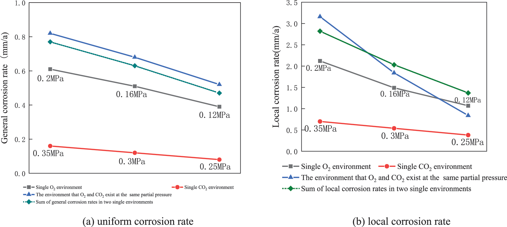
Figure 9: J55 steel in different corrosive media under the uniform corrosion rate and local corrosion rate
The three sets of O2/CO2 coexistence environments correspond to the gas environment of the extraction well after injection of 10%, 8%, and 6% oxygen-reduced air, respectively. As seen in Fig. 9a, the sum of the uniform corrosion rate of a single O2 environment and CO2 environment is compared with the consistent corrosion rate of the O2 and CO2 coexistence environment under the same partial pressure. O2 and CO2 coexistence environments were found to have a significant synergistic effect on the overall corrosion of J55 steel.
As seen in Fig. 9b, the coexistence of O2 and CO2 gradually changes from promoting pitting to inhibiting pitting as the degree of oxygen-reduced air flooding increases. Combined with the microscopic morphology and XRD patterns, it is observed that the FeCO3 crystals are finer and shift toward iron oxides when the oxygen concentration is higher. With the increased degree of oxygen-reduction, FeCO3 can form a denser corrosion product film on the material surface. This can significantly weaken the synergistic pitting effect of O2 and CO2, reducing the risk of pitting and perforation of J55 steel pipes.
(1) When the oxygen concentration of 10% oxygen-reducing air is injected, the oxygen concentration and CO2 concentration in the extraction well are high. It mainly shows the characteristics of oxygen corrosion, generating a large amount of iron oxide and a small amount of ferrous carbonate. As the oxygen-reducing air flooding increases, the oxygen concentration and CO2 concentration in the extraction well decrease simultaneously, gradually showing the characteristics of CO2 corrosion. A small number of iron oxides accompany the main corrosion product of ferrous carbonate.
(2) In the extraction well fluid medium, the environment contains both O2 and CO2, and the uniform corrosion rate is greater than the sum of the uniform corrosion rate in a single O2 and a single CO2 environment at the same partial pressure. Thus, the synergistic effect of O2 and CO2 accelerates the overall corrosion of J55 steel.
(3) When O2 and CO2 coexist, CO2 accumulates on the surface of J55 steel at the site of pitting corrosion and increases the pitting further. The accumulation of CO2 at the pitting site will aggravate the pitting corrosion of J55 steel. The local corrosion rate of J55 steel in oxygen-reduced air with 6% oxygen concentration decreased by 2.32 mm/a compared with that in oxygen-reduced air with 10% oxygen concentration. This demonstrates that oxygen-reducing has an obvious effect of inhibiting pitting corrosion.
(4) As long as the cost of oxygen reduction allows, the degree of oxygen reduction of oxygen-reducing air drive is increased to 6%, which can guarantee the safety of the gas injection process. Moreover, the corrosion of J55 steel is significantly reduced, but corrosion protection measures such as corrosion inhibitors or anti-corrosion coatings are still needed to meet the site corrosion protection needs.
Funding Statement: Major national science and technology projects “Key Techniques for the Development of Low Abundance Tight Low Permeability Reservoirs” (2016ZX05048).
Conflicts of Interest: The authors declare that they have no conflicts of interest to report regarding the present study.
References
1. Moore, R. G., Mehta, S. A., Ursenbach, M. G. (2002). A guide to high pressure air injection (HPAI) based oil recovery. SPE/DOE Improved Oil Recovery Symposium, SPE-75207-MS. Tulsa, Oklahoma. [Google Scholar]
2. Liao, G., Wang, H., Wang, Z., Tang, J., Wang, B. et al. (2020). Oil oxidation in the whole temperature regions during oil reservoir air injection and development methods. Petroleum Exploration and Development, 47(2), 357–364. https://doi.org/10.1016/S1876-3804(20)60052-0 [Google Scholar] [CrossRef]
3. Ji, Y., Zhou, L., Zhao, Z. (2027). Risk analysis and safety control technology of air injection oil recovery process. Petrochemical Safety and Environmental Protection Technology, 23(3), 19–22. [Google Scholar]
4. Ren, S. (2016). Study on mixing and explosion propagation laws of natural gas in confined space. Journal of Safety Science and Technology, 12(11), 130–135. [Google Scholar]
5. Dong, B., Zeng, D., Yu, Z., Cai, L., Yu, H. et al. (2021). Major corrosion influence factors analysis in the production well of CO2 flooding and the optimization of relative anti-corrosion measures. Journal of Petroleum Science and Engineering, 200, 108052. https://doi.org/10.1016/j.petrol.2020.108052 [Google Scholar] [CrossRef]
6. Zeng, D., Dong, B., Zeng, F., Yu, Z., Zeng, W. et al. (2021). Analysis of corrosion failure and materials selection for CO2-H2S gas well. Journal of Natural Gas Science and Engineering, 86, 103734. https://doi.org/10.1016/j.jngse.2020.103734 [Google Scholar] [CrossRef]
7. Huang, T., Ma, F., Fan, D., Liu, F., Zhao, M. (2020). Study on oxygen corrosion behavior of N80 casing steel by partial pressure ratio of CO2 and O2. Petroleum Knowledge, 12(2), 58–59. [Google Scholar]
8. Zhu, C., Liu, G., Dong, S., Li, X., Dong, B. et al. (2019). Effect of temperature on the corrosion of 3Cr steel in CO2-O2 environment species. Journal of Iron and Steel Research, 31(6), 573–581. [Google Scholar]
9. Zhang, J., Lin, X., Lu, S., Wang, T., Liu, W. et al. (2013). Corrosion behavior and mechanism of N80 steel under high temperature CO2-O2 coexisting condition. Corrosion 2013, 1121–1130, Orlando, Florida. [Google Scholar]
10. Zhang, S., Hou, L., Du, H., Wei, H., Liu, B. et al. (2020). A study on the interaction between chloride ions and CO2 towards carbon steel corrosion. Corrosion Science, 167, 108531. https://doi.org/10.1016/j.corsci.2020.108531 [Google Scholar] [CrossRef]
11. Zhang, S., Li, Y., Liu, B., Mou, L., Yu, S. et al. (2022). Understanding the synergistic effect of CO2, H2S and fluid flow towards carbon steel corrosion. Vacuum, 196, 110790. https://doi.org/10.1016/j.vacuum.2021.110790 [Google Scholar] [CrossRef]
12. Raman, A. (1996). Reviews on corrosion inhibitor science and technology. 89 symposium. [Google Scholar]
13. Wei, B. (1984). Theory and application of corrosion of metals, pp. 264–266. Beijing, China: Chemical Industry Press. [Google Scholar]
14. Wang, J., Lai, X., Wang, Q., Gao, H., Sun, Y. et al. (2007). Experimental study on oil drive by air injection in Zhongyuan oilfield. Petroleum Drilling Technology, 35(2), 5–7. [Google Scholar]
15. Zhou, Q. (2009). Research on corrosion and corrosion protection of pipe column in air injection oil drive process (Ph.D. Thesis). China University of Petroleum, Qingdao. [Google Scholar]
16. Xie, T., Lin, H., Xu, J., Dou, P., Chen, Y. et al. (2017). CO2 corrosion behavior of different materials of oil casing steel. Surface Technology, 46(1), 211–217. [Google Scholar]
17. Kermani, M. B., Morshed, A. (2003). Carbon dioxide corrosion in oil and gas production a compendium. Corrosion, 59(8). https://doi.org/10.5006/1.3277596 [Google Scholar] [CrossRef]
18. Wang, N., Lu, Z., Shi, X. (2013). Oxygen corrosion prevention and control technology in tahe oilfield. Surface Corrosion Control, 27(8), 48–50. [Google Scholar]
19. Zhang, X., Liu, J., Yi, Y., Liu, W., Sun, L. (2006). Challenges and development of Gas injection recovery enhancement technology--Air injection low temperature oxidation technology. Special Oil and Gas Reservoirs, 13(1), 6–9. [Google Scholar]
20. Yu, Z., Zeng, D., Lin, Y., Zeng, G., Feng, Y. et al. (2020). Investigations on the oxygen corrosion behaviors of p110 steel in a dynamic experiment simulating nitrogen injection. Materials and Corrosion, 71(8), 1375–1385. https://doi.org/10.1002/maco.202011490 [Google Scholar] [CrossRef]
21. Sun, Y., Fu, C., Yang, X. (2012). Corrosion analysis of oil pipe in injection exploitation of high temperature multicomponent thermal fluid. Chemical Engineering of Oil & Gas, 41(4), 408–410. [Google Scholar]
22. Wang, L., Hu, R., Wang, X. H. (2006). The oxygen corrosion behavior of S135 drill pipe steel in drill fluid. Petroleum Machinery, 34(10), 1–4. [Google Scholar]
23. Lin, X., Liu, W., Zhang, J., Dong, S., Zhang, H. et al. (2013). Characteristics of corrosion scale of 3Cr steel at high temperature and pressure in an O2 and CO2 environment. Acta Physico-Chimica Sinica, 29(11), 2405–2414. https://doi.org/10.3866/PKU.WHXB201309171 [Google Scholar] [CrossRef]
24. Li, X. (2018). Experimental study on oxygen corrosion law and protection of downhole string in air injection process. Science Technology and Engineering, 18, 18–25. [Google Scholar]
25. Khalaj, G., Pouraliakbar, H., Arab, N., Nazerfakhari, M. (2015). Correlation of passivation current density and potential by using chemical composition and corrosion cell characteristics in HSLA steels. Measurement, 75, 5–11. https://doi.org/10.1016/j.measurement.2015.07.048 [Google Scholar] [CrossRef]
26. Khalaj, G., Khalaj, M. J. (2016). Investigating the corrosion of the heat-affected zones (HAZs) of API-x70 pipeline steels in aerated carbonate solution by electrochemical methods. International Journal of Pressure Vessels and Piping, 145, 1–12. https://doi.org/10.1016/j.ijpvp.2016.06.001 [Google Scholar] [CrossRef]
27. Kiahosseini, S. R., Mohammadi Baygi, S. J., Khalaj, G., Khoshakhlagh, A., Samadipour, R. (2018). A study on structural, corrosion, and sensitization behavior of ultrafine and coarse grain 316 stainless steel processed by multiaxial forging and heat treatment. Journal of Materials Engineering and Performance, 27(1), 271–281. https://doi.org/10.1007/s11665-017-3095-7 [Google Scholar] [CrossRef]
28. Boga, H. I., Ludwig, W., Brune, A. (2003). Sporomusa aerivorans sp. nov., an oxygen-reducing homoacetogenic bacterium from the gut of a soil-feeding termite. International Journal of Systematic and Evolutionary Microbiology, 53(5), 1397–1404. https://doi.org/10.1099/ijs.0.02534-0 [Google Scholar] [PubMed] [CrossRef]
Cite This Article
 Copyright © 2023 The Author(s). Published by Tech Science Press.
This work is licensed under a Creative Commons Attribution 4.0 International License , which permits unrestricted use, distribution, and reproduction in any medium, provided the original work is properly cited.
 Downloads
 Citation Tools