
 Submit a Paper
 Propose a Special lssue
 Open Access
ARTICLE
Jet Characteristics and Optimization of a Cavitation Nozzle for Hydraulic Fracturing Applications
1
Shenzhen South China Sea Oil Economic Development Co., Ltd., Shenzhen, 518000, China
2
Guangzhou Marine Geological Survey, China Geological Survey, Guangzhou, 511458, China
3
National Engineering Research Center of Gas Hydrate Exploration and Development, Guangzhou, 511458, China
* Corresponding Authors: Zhenqiang Xu. Email: ; Kaixiang Shen. Email:
Fluid Dynamics & Materials Processing 2024, 20(1), 179-192. https://doi.org/10.32604/fdmp.2023.030499
Received 10 April 2023; Accepted 04 August 2023; Issue published 08 November 2023
 View Full Text
 Download PDF
Abstract
Hydraulic jetting is a form of fracturing that involves using a high-pressure jet of water to create fractures in the reservoir rock with a nozzle serving as the central component of the hydraulic sandblasting perforation tool. In this study, the flow behavior of the nozzle is simulated numerically in the framework of a SST k-ω turbulence model. The results show that the nozzle structure can significantly influence the jet performance and related cavitation effect. Through orthogonal experiments, the nozzle geometric parameters are optimized, and the following configuration is found accordingly: contraction angle 20°, contraction segment length 6 mm, cylindrical segment diameter 6 mm, cylindrical segment length 12 mm, spread segment length 10 mm, and spread angle 55°.Keywords
Hydraulic fracturing is an extensively employed technique in the oil and gas industry to enhance the productivity of reservoirs [1,2]. The process comprises injecting high-pressure fracturing fluid into the reservoir to create fractures in the rock formation, thereby facilitating the flow of oil and gas to the wellbore and ultimately increasing the production rate [3]. Reservoir hydraulic jetting is one form of hydraulic fracturing that involves using a high-pressure jet of water to create fractures in the reservoir rock [4,5]. This technique is especially advantageous in low-permeability reservoirs where traditional hydraulic fracturing may not be effective [6,7]. The jetting process generates a network of fractures that can enhance the permeability of the reservoir and improve overall production. Hydraulic sandblasting perforation is a crucial element of the hydraulic fracturing process, with the nozzle serving as the central component of the hydraulic sandblasting perforation tool [8]. The nozzle’s design plays a crucial role in determining its wear resistance and jet performance, which directly impacts the depth of penetration and rock-crushing volume of the hydraulic sandblasting perforation process. Ultimately, the efficiency of the perforation process is affected by the nozzle’s design and performance, making it a vital component of the hydraulic perforation tool [9,10].
Cavitation nozzles have been widely used in various fields due to their ability to spray fluid in high-speed airflow [11–13]. However, the cavitation phenomenon can cause serious damage to the nozzle and surrounding structures, which has limited the application of the technology. Thus, it is important to study the flow field characteristics and structural optimization of cavitation nozzles to improve their performance and reliability. In recent years, researchers have made significant progress in the investigation of flow field characteristics and structural optimization of cavitation nozzles [14]. The study of flow field characteristics of cavitation nozzles has been a major research direction in recent years. Through numerical simulations and experimental investigations, researchers have gained insights into the mechanisms underlying cavitation, including cavitation inception, growth, and collapse. For example, the study of liquid film cavitation nozzles has revealed that the stability of the liquid film is crucial for achieving high-speed cavitation and improving the reliability of the nozzle [14]. Researchers have proposed various methods for optimizing the flow field characteristics of cavitation nozzles, such as changing the nozzle geometric structure, improving the material properties, and adding coatings to the nozzle surface [15].
Structural optimization is another important aspect of cavitation nozzle research. The design of an optimal nozzle structure can greatly enhance the cavitation performance and prolong the service life of the nozzle [16]. Researchers have proposed various methods for optimizing the structure of cavitation nozzles, such as changing the nozzle geometry, improving the material properties, and adding coatings to the nozzle surface. For example, the optimization of the nozzle shape can significantly reduce cavitation erosion and prolong the service life of the nozzle [17,18]. Furthermore, the study of structural optimization can also contribute to the development of new types of cavitation nozzles, such as the super-cavitation nozzle, which can create a super-cavity around the nozzle and greatly reduce drag.
In summary, the study of flow field characteristics and structural optimization of cavitation nozzles is an important research direction in the development of hydraulic fracturing technology. Therefore, it is necessary to analyze the influence of nozzle parameters on jet performance under the conditions of reservoir perforation operations and prefer high-performance nozzle structures accordingly. This study selects the angle cavitation nozzle as the research object due to its better cavitation performance. Computational fluid dynamics (CFD) is adopted to calculate to conduct numerical simulations of the nozzle jet flow characteristics. The structural parameters of the angel nozzle are optimized using the evaluation indicator of gas volume fraction. The research results have important guiding significance for the structural optimization of hydraulic perforation nozzles.
Fig. 1 shows the two-dimensional axisymmetric model of the jet flow field of the conical-cylindrical nozzle, which is used to calculate the internal and external flow field characteristics. Four factors significantly affect the jet performance of the conical-cylindrical nozzle: contraction angle, contraction segment length, cylindrical segment length, and cylindrical segment diameter.
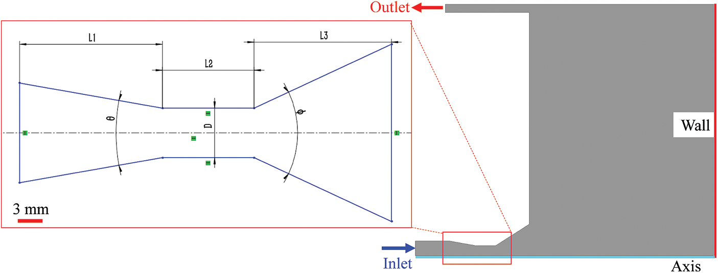
Figure 1: Physical model of nozzle jet flow field and schematic diagram of angle nozzle geometric parameters
Grid meshing is a critical step in numerical simulation. High-quality grids must be used as the basis to obtain high-precision calculation results. In order to simulate a flow problem accurately, the appropriate grid needs to be meshed based on the practical problem [19]. The nozzle wall is refined with a boundary layer to improve the calculation accuracy. The calculation model of the jet flow field is meshed using a quadrilateral grid. In this paper, the appropriate meshing strategy is determined by grid independence analysis. The influence of near-wall grid size on the gas volume fraction is given in Fig. 2. It can be seen that as the grid size decreases, the gas volume fraction increases slowly, and when the mesh size decreases to 0.05 mm, the gas volume fraction gradually tends to be stable. Therefore, the first layer grid size is determined to be 0.05 mm for the numerical simulation. The computational domain is divided into 138732 grid cells, as shown in Fig. 3.
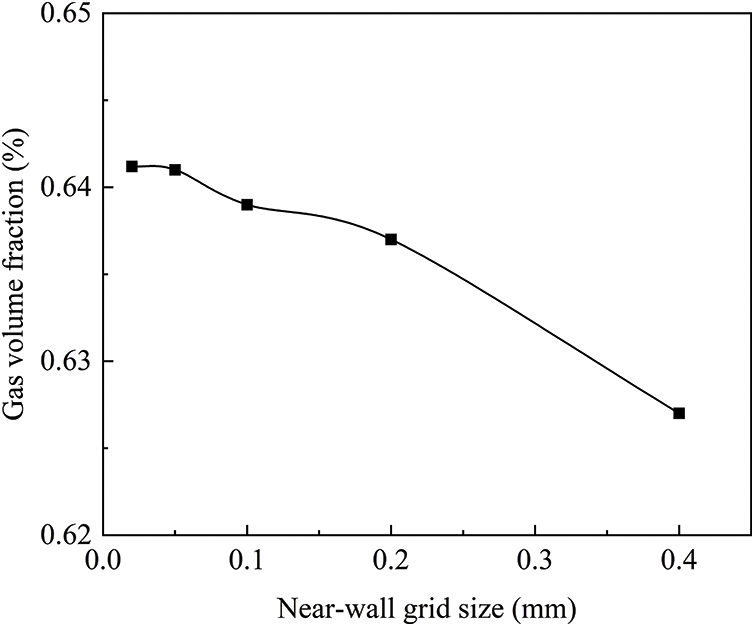
Figure 2: The influence of near-wall grid size on nozzle pressure loss
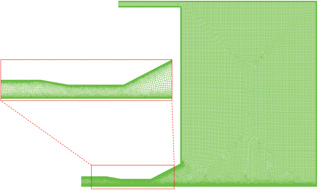
Figure 3: Computational grid of nozzle jet flow field
Compared to other turbulence models, the SST k-ω model can better handle wall-confined flows with high strain rates and large curvature of streamlines. The SST k-ω model has advantages in predicting near-wall and vortex flow and is suitable for boundary layer flow, separation, and transition in adverse pressure gradients [20]. In this paper, the SST k-ω turbulence model with non-equilibrium wall functions is adopted to solve the turbulence field of the nozzle. The basic control equations are:
where i, j are coordinate direction and the direction of the velocity components, respectively; ui, uj are the speed of different coordinate directions, respectively; ρ is the water density; μ is dynamic viscosity;
2.4 Boundary Conditions and Parameter Settings
In order to compare the hydraulic characteristics of nozzles jet with different geometric parameters and exclude the effect of other factors on the simulation results, simulation calculations using the same set of parameters, specific to: inlet is velocity-inlet; outlet is pressure-out; the model surface is wall without slip solid wall; x-axis is set as axisymmetric boundary condition. In numerical simulations, the Zwart-Gerber-Belamri cavitation model is employed, and the cavitation pressure is set to 3540 Pa. The discrete format is SMIPLEC, the momentum equation and turbulent kinetic energy are measured using second-order accuracy upwind scheme to ensure accuracy and stability. The numerical simulations are conducted under submerged jet conditions.
3.1 Analysis of Flow Field Characteristics
Under the condition of jet flow rate Q = 0.33 m3/min, the flow field characteristics of the angle nozzle with geometric parameters of θ = 30°, D = 6 mm, L1 = 8 mm, L2 = 6 mm, L3 = 10 mm, Φ = 40° are investigated.
Figs. 4 and 5 respectively present the velocity contour and velocity vector of the angle nozzle jet, revealing that the flow velocity is greatest in the cylindrical section of the nozzle. As the jet exits the nozzle, it experiences shear forces with the external fluid, leading to a gradual decrease in the radius of the jet iso-velocity core.

Figure 4: Flow field velocity contour

Figure 5: Flow field velocity vector
Fig. 6 displays the static pressure contour of the angle nozzle jet, indicating that the pressure begins to decrease from the contraction section of the nozzle. Negative pressure exists in the nozzle spread section, causing the fluid to undergo a phase change from liquid to gas and leading to a cavitation phenomenon.

Figure 6: Flow field pressure contour
3.1.3 Gas-Phase Volume Distribution
Once the static pressure of the flow field drops below the cavitation pressure, gas bubbles will form in the liquid water. Fig. 7 presents the gas volume fraction contour of the angle nozzle, where the cavitation zone is mainly concentrated near the wall of the nozzle spread section.

Figure 7: Flow field gas volume fraction contour
3.2 Effect of Cavitation Nozzle Geometric Parameters
The geometric parameters of the angle nozzle significantly affect the cavitation effect. Reasonable geometric parameter design is the key to achieving low energy consumption and efficient perforation. This study first uses a single-factor analysis method to investigate the effects of different nozzle geometric parameters on pressure loss, velocity distribution, and cavitation effect of the jet flow field. Then, combining with the orthogonal experimental method, the optimal geometric parameters of the angle nozzle are determined, providing theoretical guidance for the structural design of the cavitation nozzle.
Firstly, keeping other parameters constant in the numerical simulations (Q = 0.33 m3/min, D = 6 mm, L1 = 8 mm, L2 = 6 mm, L3 = 10 mm, Φ = 40°), the influence of different contraction angles on the jet performance is analyzed. The effect of contraction angle on the jet performance is obtained, as shown in Fig. 8. Fig. 8a shows the variation of the gas volume fraction and pressure loss of the nozzles with different contraction angles. It can be observed that the gas volume fraction and the nozzle pressure loss both increase with increasing contraction angle. This is because the larger the contraction angle, the larger the windward area of the jet flowing through the nozzle contraction section, and the greater the pressure drag that the jet experiences. To pass through the same flow rate, a greater pressure loss is required. Besides, the larger the contraction angle, the greater the pressure gradient at the nozzle contraction section, and the gas volume fraction also increase accordingly.
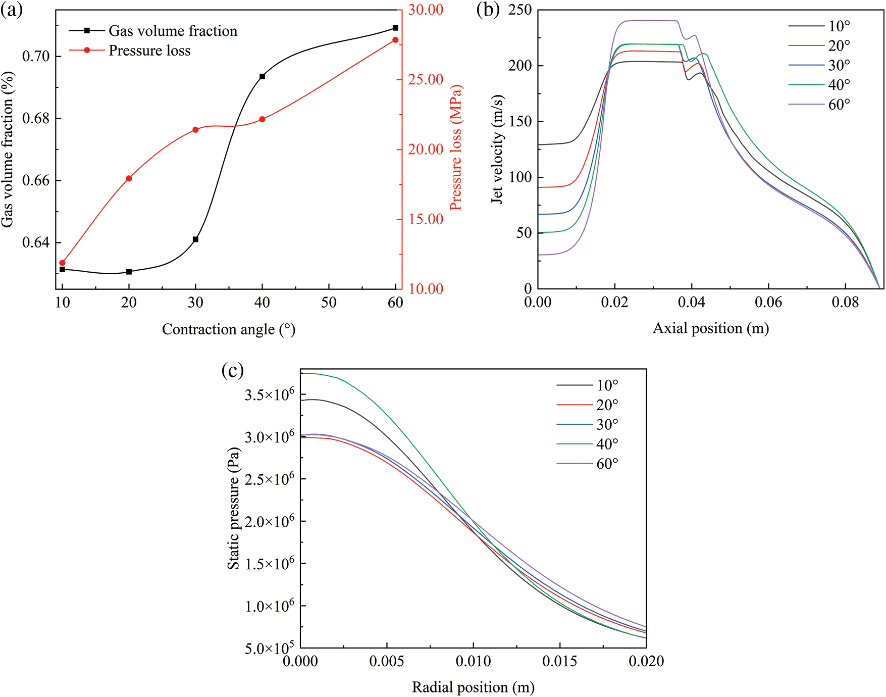
Figure 8: Effect of contraction angle on the jet performance: (a) variation law of gas volume fraction and pressure loss; (b) velocity distribution along the nozzle axis; (c) impact pressure distribution
Fig. 8b shows the axial velocity distribution curves of the jet corresponding to different contraction angles. It indicates that the contraction angle affects the maximum velocity of the nozzle and the velocity decay rate of the jet. When the contraction angle is 60°, the jet accelerates the fastest in the contraction section of the nozzle, but the velocity decay after flowing out of the nozzle is also the fastest. Fig. 8c shows the wall impact pressure distribution curves corresponding to different contraction angles. It can be seen that the nozzle with a contraction angle of 40° generates the largest impact force, followed by the nozzle with a contraction angle of 10°. However, the pressure loss of the nozzle with a contraction angle of 40° is 10 MPa higher than that of the nozzle with a contraction angle of 10°. Therefore, when performing perforation operations, the nozzle with a contraction angle of 10° should be given priority.
3.2.2 Contraction Segment Length
Then, keeping other parameters constant in the numerical simulations (Q = 0.33 m3/min, θ = 30°, D = 6 mm, L2 = 6 mm, L3 = 10 mm, Φ = 40°), the influence of different contraction segment lengths on the jet performance is analyzed. The effect of contraction segment length on the jet performance is obtained, as shown in Fig. 9. Fig. 9a shows the variation of the gas volume fraction and pressure loss of the nozzles with different contraction segment lengths. The results indicate that, under constant jet flow, the nozzle pressure loss increases almost linearly with the contraction section length. Increasing the contraction section length simultaneously increases the viscous drag and the pressure drag of the jet flow passing through the nozzle, requiring more energy consumption. The gas volume fraction of the jet flow increases slowly at first, then decreases slowly with the increase of the contraction section length. The nozzle jet flow achieves the maximum gas content when the contraction section length is 8 mm.

Figure 9: Effect of contraction segment length on the jet performance: (a) variation law of gas volume fraction and nozzle pressure loss; (b) velocity distribution along the nozzle axis; (c) impact pressure distribution
Figs. 9b and 9c show the effect of the contraction segment length on the velocity distribution along the nozzle axis and the radial pressure distribution on the jet impact wall, respectively. Under the constant jet flow rate condition, the contraction segment length does not affect the jet iso-velocity core. Besides, the jet impact force is the largest when the nozzle contraction section length is 6 mm. The cavitation effect of this nozzle is ideal and the pressure loss is small, so it should be given priority in perforation operations.
3.2.3 Cylindrical Segment Length
Then, keeping other parameters constant in the numerical simulations (Q = 0.33 m3/min, θ = 30°, D = 6 mm, L1 = 8 mm, L3 = 10 mm, Φ = 40°), the influence of different cylindrical segment lengths on the jet performance is analyzed. The effect of cylindrical segment length on the jet performance is obtained, as shown in Fig. 10. Fig. 10a shows the variation of the gas volume fraction and nozzle pressure loss with different cylindrical segment lengths. The results indicate that with the increase of the cylindrical section length, both the gas volume fraction and the pressure loss of the jet flow field change very little.

Figure 10: Effect of cylindrical segment length on the jet performance: (a) variation law of gas volume fraction and nozzle pressure loss; (b) velocity distribution along the nozzle axis; (c) impact pressure distribution
Figs. 10b and 10c show the effect of the cylindrical segment length on the velocity distribution along the nozzle axis and the radial pressure distribution on the jet impact wall, respectively. It can be observed that the maximum axial velocity of the jet is not affected by the cylindrical section length. However, the cylindrical section length has a significant effect on the impact force of the jet. The impact force is highest when the length is 12 mm, and lowest when the length is 8 mm. Taking all factors into consideration, it is preliminarily determined that the cylindrical segment length of the nozzle is 10 mm.
Similarly, keeping other parameters constant in the numerical simulations (Q = 0.33 m3/min, θ = 30°, L1 = 8 mm, L2 = 6 mm, Φ = 40°), the influence of different spread segment lengths on the jet performance is analyzed. The effect of spread segment length on the jet performance is obtained, as shown in Fig. 11. Fig. 11a shows the variation of the gas volume fraction and pressure loss of the nozzles with different spread segment lengths. The spread segment length has a significant effect on the cavitation effect of the jet, but has little effect on the nozzle pressure loss. As the spread segment length increases, the gas volume fraction of the flow field increases approximately linearly. This is because the cavitation zone of the jet is mainly concentrated in the spread section of the angle nozzle.

Figure 11: Effect of spread segment length on the jet performance: (a) variation law of gas volume fraction and nozzle pressure loss; (b) velocity distribution along the nozzle axis; (c) impact pressure distribution
Figs. 11b and 11c show the effect of the spread segment length on the velocity distribution along the nozzle axis and the radial pressure distribution on the jet impact wall, respectively. Under the constant jet flow rate condition, the jet iso-velocity is the same, but the decay rate of jet velocity increases with the spread segment length after the jet is ejected from the nozzle, resulting in a reduction of the impact force of the jet with the increase of the spread segment length. The rock-breaking process of the cavitation nozzle depends on both the impact of the jet and the collapse of cavitation bubbles. The preliminary optimal spread section length of the angle nozzle is determined to be 10 mm.
Finally, keeping other parameters constant in the numerical simulations (Q = 0.33 m3/min, θ = 30°, D = 6 mm, L1 = 8 mm, L2 = 6 mm, L3 = 10 mm), the influence of different spread angles on the jet performance is analyzed. The effect of spread angle on the jet performance is obtained, as shown in Fig. 12. Fig. 12a shows the variation of the gas volume fraction and pressure loss of the nozzles with different spread angles. It can be observed that the spread angle has a significant impact on the cavitation effect of the jet, but has little effect on the nozzle pressure loss. As the spread angle increases, the wall length of the nozzle spread section increases, which is beneficial to the generation and attachment of cavitation bubbles. The gas volume fraction of the jet flow field also increases.

Figure 12: Effect of spread angle on the jet performance: (a) variation law of gas volume fraction and pressure loss; (b) velocity distribution along the nozzle axis; (c) impact pressure distribution
Figs. 12b and 12c show the effect of the spread angle on the velocity distribution along the nozzle axis and the radial pressure distribution on the jet impact wall, respectively. As can be seen, the decay rate of the jet velocity increases with the increase of the spread angle, resulting in a reduction of the impact force of the jet with the increase of the spread angle. Similar to the law of the contraction segment of the nozzle, the higher the spread angle, the higher the cavitation efficiency, but the lower the impact force of the jet. Therefore, further jet rock-breaking experiments are needed to determine the optimal length of the spread section.
4 Optimization Design of Angle Nozzle Geometric Parameters
The orthogonal experiment is an efficient method of experimental design that can determine the impact of each factor through a small number of experiments, saving time and labor while selecting the optimal level combination. To reduce the workload of the numerical simulation in this study, an orthogonal experiment method is employed to optimize the nozzle geometric parameters. The gas volume fraction serves as the evaluation index. The four experimental factors that significantly affect the cavitation characteristics of the nozzle are nozzle contraction angle θ, cylindrical segment length L2, spread segment length L3, and spread angle Φ. Each experimental factor is taken at three levels, using L9 (34) orthogonal table and referring to the simulation results in Section 3.2 to determine the level range of each factor.
Table 1 presents the detailed geometric parameter settings and orthogonal analysis results for a pressure drop of 15 MPa. The numerical simulations of different geometric models are conducted according to the orthogonal experimental scheme. The geometric parameters for the angle nozzle with the best cavitation performance are optimized, providing theoretical guidance for future abrasive jet rock-breaking experiments. The results indicate that the primary and secondary factors affecting the cavitation effect are: Φ > L2 > θ > L3. Meanwhile, the angle nozzle geometric parameters are preliminarily optimized: the contraction angle is 20°, the contraction segment length is 6 mm, the cylindrical segment diameter is 6 mm, the cylindrical segment length is 12 mm, the spread segment length is 10 mm, and the spread angle is 55°.

In this paper, the SST k-ω turbulence model is used to numerically simulate the jet characteristics of angle cavitation nozzles with different geometric structures, and single-factor analysis and orthogonal experimental methods are used to optimize the nozzle structure parameters. The nozzle structure parameters have a significant influence on the jet performance, particularly on nozzle pressure drop, jet impact pressure, and cavitation effect.
The primary and secondary factors affecting the cavitation effect of the nozzle are spread angle > cylindrical segment length > contraction angle > spread segment length. Meanwhile, the angle nozzle geometric parameters are preliminarily optimized: the contraction angle is 20°, the contraction segment length is 6 mm, the cylindrical segment diameter is 6 mm, the cylindrical segment length is 12 mm, the spread segment length is 10 mm, and the spread angle is 55°. In hydraulic perforating operations, the rock is broken by the combined action of cavitation effects and jet impact pressure. In the later stage, the angle nozzle structure should be further optimized and designed in combination with the indoor jet-breaking experiment.
Acknowledgement: None.
Funding Statement: The authors gratefully acknowledge the financial support by the Marine Economy Development Foundation of Guangdong Province “Technical Support for Stimulation and Testing of Gas Hydrate Reservoirs” (GDNRC[2022]44).
Author Contributions: The authors confirm contribution to the paper as follows: study conception and design: Zhenqiang Xu; data collection: Yu Gao; analysis and interpretation of results: Kaixiang Shen; draft manuscript preparation: Yu Gao. All authors reviewed the results and approved the final version of the manuscript.
Availability of Data and Materials: Data available on request.
Conflicts of Interest: The authors declare that they have no conflicts of interest to report regarding the present study.
References
1. Osiptsov, A. (2017). Fluid mechanics of hydraulic fracturing: A review. Journal of Petroleum Science and Engineering, 156, 513–535. [Google Scholar]
2. Tian, S., Li, G., Huang, Z. (2009). Investigation and application for multistage hydrajet-fracturing with coiled tubing. Petroleum Science and Technology, 27(13), 1494–1502. [Google Scholar]
3. Barati, R., Liang, J. (2014). A review of fracturing fluid systems used for hydraulic fracturing of oil and gas wells. Journal of Applied Polymer Science, 131(16), 40735. [Google Scholar]
4. Li, J., Li, G., Huang, Z. (2017). A discussion about the method to study the effect of ambient pressure on hydraulic jetting. Journal of Petroleum Science and Engineering, 149, 203–207. [Google Scholar]
5. Davarpanah, A., Shirmohammadi, R., Mirshekari, B. (2019). Analysis of hydraulic fracturing techniques: Hybrid fuzzy approaches. Arabian Journal of Geosciences, 12, 1–8. [Google Scholar]
6. Zhou, F., Su, H., Liang, X., Meng, L., Yuan, L. et al. (2019). Integrated hydraulic fracturing techniques to enhance oil recovery from tight rocks. Petroleum Exploration and Development, 46(5), 1065–1072. [Google Scholar]
7. Cai, W., Qin, G., An, Y. (2012). Study on horizontal well fracture in low permeability reservoirs. Advanced Materials Research, 524, 1587–1590. [Google Scholar]
8. Tian, J., Wen, F., Ge, T. (2022). Simulation and experimental study on hydraulic sandblasting cutting in uncontrolled blowout well. Journal of Pressure Vessel Technology, 144(2), 21404. [Google Scholar]
9. He, L., Liu, Y., Shen, K., Yang, X., Ba, Q. (2021). Numerical research on the dynamic rock-breaking process of impact drilling with multi-nozzle water jets. Journal of Petroleum Science and Engineering, 207, 109145. [Google Scholar]
10. Wang, D. (2012). Development of rock breaking technology by means of high-pressure water jet assistant machine. Tunnel Construction, 32(S2), 47–50. [Google Scholar]
11. Soyama, H. (2020). Cavitating jet: A review. Applied Sciences, 10(20), 7280. [Google Scholar]
12. Li, Z. (2014). Criteria for jet cavitation and cavitation jet drilling. International Journal of Rock Mechanics and Mining Sciences, 71, 204–207. [Google Scholar]
13. Sou, A., Hosokawa, S., Tomiyama, A. (2007). Effects of cavitation in a nozzle on liquid jet atomization. International Journal of Heat and Mass Transfer, 50(17–18), 3575–3582. [Google Scholar]
14. Payri, F., Bermúdez, V., Payri, R. (2004). The influence of cavitation on the internal flow and the spray characteristics in diesel injection nozzles. Fuel, 83(4–5), 419–431. [Google Scholar]
15. Macián, V., Payri, R., Margot, X. (2003). A CFD analysis of the influence of diesel nozzle geometry on the inception of cavitation. Atomization and Sprays, 13(5–6), 579–604. [Google Scholar]
16. Schmidt, D., Rutland, C., Corradini, M. (1997). A numerical study of cavitating flow through various nozzle shapes. SAE Transactions, 1, 1664–1673. [Google Scholar]
17. Sun, Z., Li, G., Chen, C. (2015). Numerical investigation on effects of nozzle’s geometric parameters on the flow and the cavitation characteristics within injector’s nozzle for a high-pressure common-rail DI diesel engine. Energy Conversion and Management, 89, 843–861. [Google Scholar]
18. Wu, X., Zhang, Y., Tan, Y. (2022). Flow-visualization and numerical investigation on the optimum design of cavitating jet nozzle. Petroleum Science, 19(5), 2284–2296. [Google Scholar]
19. Katz, A., Sankaran, V. (2011). Mesh quality effects on the accuracy of CFD solutions on unstructured meshes. Journal of Computational Physics, 230(20), 7670–7686. [Google Scholar]
20. Shi, J., Ge, S., Sheng, X. (2022). Numerical investigation on the aerodynamic noise generated by a simplified double-strip pantograph. Fluid Dynamics & Materials Processing, 18(2), 463–480. https://doi.org/10.32604/fdmp.2022.017508 [Google Scholar] [CrossRef]
Cite This Article
 Copyright © 2024 The Author(s). Published by Tech Science Press.
This work is licensed under a Creative Commons Attribution 4.0 International License , which permits unrestricted use, distribution, and reproduction in any medium, provided the original work is properly cited.
 Downloads
 Citation Tools