
 Submit a Paper
 Propose a Special lssue
 Open Access
ARTICLE
Investigation of Wellbore Temperature Dynamics during Cement Setting in Deepwater Shallow Formations
Guangzhou Marine Geological Survey, China Geological Survey, Guangzhou, 510075, China
* Corresponding Author: Bo Ning. Email:
(This article belongs to the Special Issue: Fluid and Thermal Dynamics in the Development of Unconventional Resources II)
Fluid Dynamics & Materials Processing 2024, 20(12), 2927-2939. https://doi.org/10.32604/fdmp.2024.057388
Received 16 August 2024; Accepted 21 November 2024; Issue published 23 December 2024
 View Full Text
 Download PDF
Abstract
Offshore deepwater cementing generally faces more challenges than onshore cementing. Shallow formations in deepwater wells often exhibit low structural strength, high porosity, and are prone to shallow gas influx and hydrate formation. These factors require careful control of hydration heat. In this article, we examine the key factors influencing temperature fluctuations in the wellbore and develop a temperature model that accounts for the thermal effects related to cement slurry circulation and hydration. This model is then applied to a deepwater shallow formation cementing case study. The results show that: (1) When cement slurry is displaced into deep-water shallow formations, it loses heat due to seawater-induced cooling before entering the wellbore. This lowers the temperature of both the slurry and the wellbore before cement hydration begins. (2) The main production of heat due to cement hydration occurs during the pre-induction and acceleration stages. These are also the critical phases that affect formation temperature in deep-water shallow formation cementing. According to Kutasov’s semi-analytical equation, the peak heat release happens 8–12 h after cementing, resulting in a temperature rise of up to 40°C and 30°C for 26″ and 12-1/4″ boreholes, respectively.Keywords
Cementing is a vital technical aspect of oil and gas well construction. It affects the production cycle and life span of the wells, and thus the success of oil and gas reservoir exploration and development. The main goal of cementing is to isolate different formations effectively and to protect the casing. This ensures that drilling and oil testing operations can be done safely and smoothly, and that formation isolation is maintained in the long run [1,2].
Deepwater oil and gas construction cementing is more difficult than onshore cementing. This is because the shallow formations in deepwater wells are soft, low-strength, and unconsolidated. They cannot bear high-density cement slurry without breaking. They also have shallow uncertainties such as shallow gas, shallow flow, and hydrates [3–5]. These uncertainties have high trap pressures that can cause gas kick or channeling if the cement slurry contacts them. They can also decompose due to temperature changes caused by cement slurry circulation and hydration, releasing large amounts of methane gas that can lead to cementing failure or subsea accidents [6–8]. Liu et al. [9] investigated the effect of cement slurry intrusion on hydrate stability during the cementing of hydrate formations. They found that cement slurry changes the hydrate phase equilibrium conditions and induces hydrate decomposition when hydrate reservoirs are exothermic to hydrate. This results in lower cementing quality or even failure. They used indoor simulation experiments and numerical simulation calculations to show that cement slurry can cause different degrees of hydrate decomposition within its penetration range in only 22 min. All hydrates within one time of the borehole wall will be decomposed. Zou et al. [10] pointed out that the integrity of cement seals in offshore oil and gas wells is prone to gas channeling due to the influence of high temperatures. Therefore, relevant research on cement slurry sealing was conducted. Through triaxial testing and high temperature curing kettle oxidation testing, physical parameters such as compressive strength, elastic modulus, and Poisson’s ratio of the samples were obtained, and the brittleness index was determined, got the impact of temperature on the performance of cement seals was also investigated. Cooke et al. [11] examined the wellbore temperature and pressure changes during cement slurry circulation. They analyzed the annulus temperature, cement slurry return, and long-term pressure drop of drilling fluid above the cement slurry during cementing. Under a large number of experiments, Lv et al. [12] analyzed the weight loss of cement slurry across a wide temperature range, with the influence of different retarders and fluid loss additives. Based on the experimental results, they noted that the weight loss curve of the cement slurry shifted from a “two-stage” to a “three-stage” pattern due to temperature variations, and optimal dosages of retarders and filtrate reducers.
Jing et al. [13], based on the gas–liquid two-phase separated method, established an improved calculation model of wellbore temperature and pressure field for offshore HPHT wells. This model can display accurate theoretical support for the rational formulation of the production plan after the well opening, to avoid excessive restrictions on the initial production rate. Zhao et al. [14] pointed out that the transient flow testing of ultra-deepwater gas wells is significantly impacted by the low temperature of seawater at great distances. Consequently, based on fluid mechanics, heat and mass transfer, as well as conservation of mass and energy, they developed a model for flow temperature and pressure fields. Using the Runge-Kutta method, they solved the wellbore temperature distribution, accurately assessing the impact of various factors on wellbore temperature. Duan et al. [15] pointed out that when the gas is stored in the wellbore, temperature and pressure changes can lead to gas hydrates, which will pose a significant danger to the production. Establish a temperature model that couples total thermal resistance and temperature in the wellbore-stratum composite medium system. Utilizing the two-phase pressure model alongside the temperature model, they conduct coupling calculations of temperature and pressure. Jia et al. [16] prepared a new kind of microcapsule sustained-release–type hydration heat inhibitor (MSR), investigated the semi-adiabatic temperature rise, setting time, and strength of low-heat Portland cement. The results showed that the MSR had a good regulating effect on the hydration of low-heat Portland cement. Yang et al. [17] studied the degree of hydration of the four major anhydrous cement phases, developed a mathematical model for kinetic analysis of portland cement hydration. This paper focuses on the influence of zeolite saturated with zinc ions on the hydration kinetics of Portland cement composites and contributes to the understanding of the hydration mechanism of cement. Swaddiwudhipong et al. [18] proposed a numerical model to simulate the exothermic hydration process of cement and temperature rise. This model considered the hydration reaction of each major mineral compound found in Portland cement, C3S, C2S, C3A and C4AF. The applicability of the proposed model is verified by a series of adiabatic temperature rise tests. With the establishment of this approach, it is possible to simulate the exothermic hydration process of Portland cement, and the temperature rise directly based on the intrinsic mechanism of hydration, the chemical composition of cement and mix proportion of concrete mixture. Lavagna et al. [19] conducted research on the chemical behavior of cement materials and provided a detailed description of the manufacturing process, chemical composition and hydration reaction, setting mechanism, pore characteristics of cement stone, and sustainable development of the cement system, covering these aspects in five separate parts. Meanwhile, they analyzed in detail the reaction process involving C3A, C2S, C3S and C4AF.
This paper analyzes the wellbore temperature distribution and the cement hydration characteristics during cement slurry circulation in a deep-water shallow formation drilling in the South China Sea. It examines the different temperature profiles during the cementing operation and the temperature changes in the deepwater shallow formation. It provides theoretical support for the safe cementing of deepwater shallow formations. The paper also fills a gap in the literature on the circulating temperature of the wellbore and formation during cementing operations and waiting on cement.
2 Temperature Change during Cement Slurry Circulation
The cementing process in deepwater shallow formations has three phases: Phase I, the drilling fluid circulation phase after the casing is placed in the wellbore. The fluid in the casing and annulus is the drilling fluid from the previous opening. Phase II, the cementing construction phase, in which the fluids in the casing and annulus change in order as follows: drilling fluid, isolation fluid, advance fluid, flushing fluid, cement slurry, and topping fluid. Phase III, waiting on cement, in which the working fluid is stationary both in casing and annulus. The circulation temperature model for phases I and II is based on the first law of thermodynamics and the basic equations of heat transfer science [20–22].
The partial differential equation for the temperature distribution during the circulation of the working fluid in the casing is:
The temperature distribution of the working fluid during the circulation in the annulus is:
The temperature distribution of the well wall during the cementing process is:
The stratigraphic temperature distribution is:
where q: circulation displacement during cementing, L/s; pi, po: pressure drop per unit length in casing and annulus, MPa; rci, rco: casing ID, OD, mm; rw: borehole diameter, mm; C1, Cf: specific heat capacity of working fluid and formation, kJ/(kg°C); Tc, Tf: fluid temperature in casing and formation temperature, °C; Ta0: annulus temperature at the end of cementing, °C; Ta: annular temperature at the end of cementing, °C; kf: formation thermal conductivity, W/(m°C); G: Ground temperature gradient, °C/m; Tin: Liquid temperature at the inlet of the casing, °C; Tout: Liquid temperature at the annular outlet, °C; hb: convective heat transfer coefficient of wellbore wall, W/(m2°C).
The initial temperature distribution of the liquid in the annulus of the casing is the undisturbed formation temperature, therefore, the initial conditions are expressed as:
The liquid temperature at the inlet of the casing and the outlet of the annulus can be directly measured, therefore the boundary conditions at the wellhead are:
The temperature of the fluid inside the casing and the fluid inside the annulus at the bottom of the well, where z = H, is the same, which is:
At the interface between the formation and the annulus fluid, the heat flowing out of the formation and into the annulus is equal, that is:
The calculation model is relatively complex, and it is obviously impractical to directly compute its analytical solution. Therefore, this paper adopts an unconditionally stable, fully implicit finite difference numerical method to solve it. First, the mathematical model is discretized in both space and time. Considering stability, the system is treated in a fully implicit manner, where all unknown variables in the energy balance equation are expressed using values from the subsequent time step to form a system of algebraic equations. Through this discretization, the solution of the original mathematical model under given boundary conditions is transformed into a solution over a defined domain. By solving the discretized system of difference equations using the Gauss-Seidel iteration method, the temperature distributions of the fluid inside the casing, the annulus fluid, and the formation at different time points under cyclic conditions can be obtained.
The fully implicit finite difference method is used to solve the above partial differential equation. The well is built in an area with a water depth of 1250 m. The drilling process uses the open circuit drilling method without risers. The casing uses 20″-9-5/8″ composite casing. The cementing displacement is 1.3 m3/min. The following figures show the fluid temperature inside the casing and the formation temperature changes during cementing based on the above equation.
This well is riser-less and has a datum temperature of 26°C. The seawater temperature drops as the water depth increases and reaches 3°C–5°C at the seabed. The cement slurry flows through the drill pipe and cools down to 12°C–15°C near the mud line due to heat exchange with seawater (see Fig. 1). Figs. 1, 2 show that the wellbore temperature slope changes at the casing redirection point. This is because the annular flow rate decreases and the annular volume increases in the 20″ casing section of the 26″ borehole, compared to the lower 9-5/8″ casing section. This affects the wellbore and formation temperature curve in this section, making it higher.
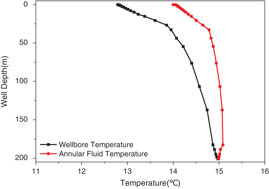
Figure 1: Wellbore temperature during cement slurry circulation
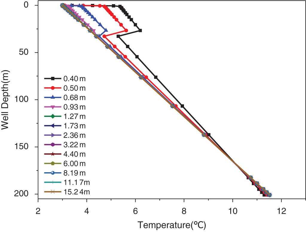
Figure 2: Distribution of formation temperature during cementing
3 Analysis of Hydration Mechanism of Oil Well Cement
3.1 Hydration Reaction of Cement Components
Currently, G-grade cement is a fundamental type of cement used in oil and gas wells according to API standards. Its composition is similar to that of ordinary silicate cement and primarily consists of tricalcium silicate (Ca3SiO5 as C3S), dicalcium silicate (Ca2SiO4 as C2S), tricalcium aluminate (Ca3Al2O6 as C3A), and tetracalcium iron aluminate (Ca4Al2Fe2O10, recorded as C4AF).
Oil well cement is a kind of multi mineral mixture, during the hydration, the cement slurry getting thickens and hardens. From a chemical perspective, hydration is a complex process involving dissolution and precipitation. The components and reaction rates vary and interact with one another. C3S and C2S are the most abundant silicate compounds in G-grade cement, typically comprising over 50% of the total material. The hydration reactions of C3S and C2S at room temperature can be summarized by the following equation:
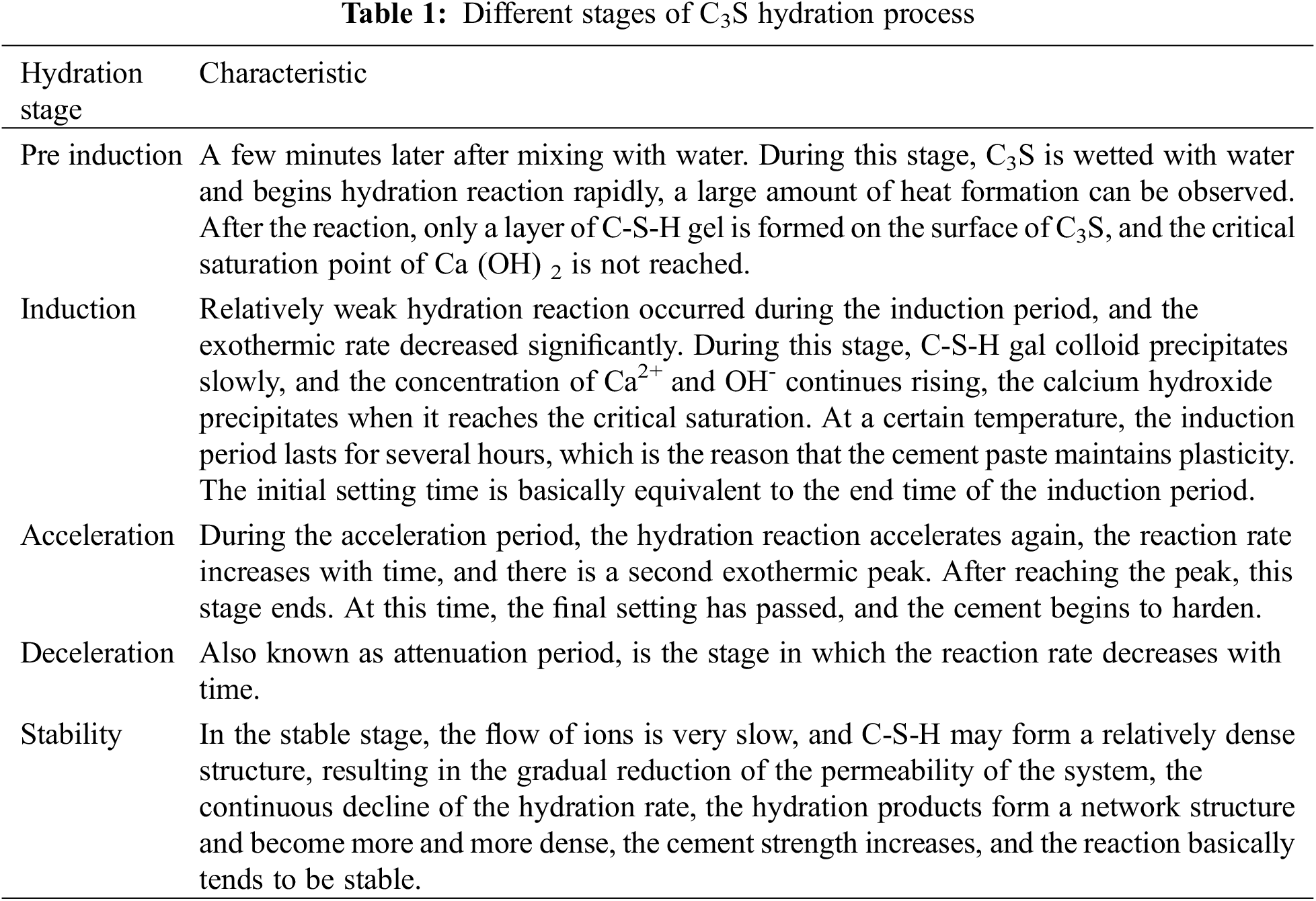
The hydration of C3S and C2S is an exothermic process that can be divided into five stages based on the relationship between heat release rate and time: pre-induction (stage I), induction (stage II), acceleration (stage III), deceleration (stage IV), and stability (stage V). The characteristics of each stage are detailed in Table 1 [23–25].
Another important component in cement clinker is tricalcium aluminate (C3A), which plays a crucial role in the early hydration of cement and the fluidity of the paste. The hydration reaction of C3A in pure water at room temperature can be roughly described by the following equation:
The hydration of C3A occurs in three stages. In stage one, C3A dissolves quickly and produces hexagonal plate-like hydration products. This dissolution results in a peak heat release while the formation of hexagonal plate-like hydration products slows the reaction rate. In stage two, the layer of hexagonal plate-like hydration products breaks down and cubic C3AH6 forms, causing the reaction to accelerate once more. In stage three, cubic C3AH6 hydration products surround C3A. Due to their crystalline network structure, the paste loses fluidity rapidly. Although C3AH6 forms a solid matrix, it can increase porosity and damage microstructure, leading to decreased paste strength.
3.2 Hydration Process of Cement
Cement is a complex mixture with numerous components. Its hydration process can generally be divided into three stages: ettringite formation, accelerated C3S hydration, and structure development and formation.
In the first stage, ettringite forms when C3A in the cement hydrates upon contact with water. This produces the initial heat release peak shown in Fig. 3. The chemical reaction during this stage can be summarized as follows:
In Eq. (9), AFt is referred to as the AFt phase. In Eq. (8), C3A reacts with Ca(OH)2 in the solution to produce hydration products C4AH13 and rapidly reacts with CSH2 under C4AH13, CSH2 certain conditions to form ettringite (
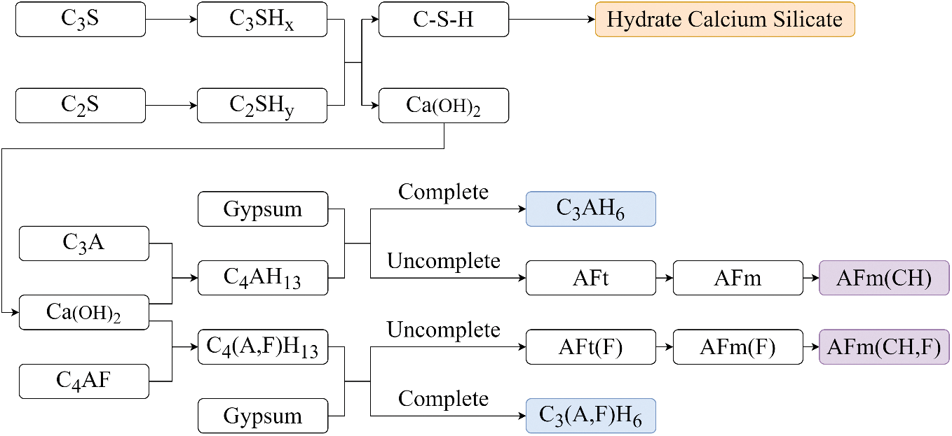
Figure 3: Cement hydration products of well cement
The second stage is accelerated C3S hydration. During this stage, C3S hydrates rapidly and forms C-S-H and CH phases, producing the second heat release peak. At this point, CSH2 in the cement has been almost completely consumed. C3S and C2S are the main components of cement, usually accounting for more than 80% of its composition. The hydration reactions of C3S and C2S are shown in Eqs. (5) and (6). The product xCaO·SiO2·yH2O is unstable and affected by temperature, additives, and curing methods. Its morphology is not fixed, and commonly referred to as a C-S-H gel, which is the main binding material in hardened cement.
The third stage is structure development and formation. During this stage, the heat release rate has decreased significantly and gradually stabilizes. The various components of cement interweave to form a hardened paste structure. The reaction products of cement hydration can be represented by the following figure.
3.3 Heat Release Model of Cement Hydration
When constructing wells in deep and shallow formations, cementing may cross shallow gas and hydrate layers. The heat released during cement hydration can significantly increase annulus temperature, destabilizing shallow gas, hydrate and compromising wellbore safety. Temperature and pressure also affect the downhole performance of cement slurry, impacting pumpability time and setting strength. Temperature has a more pronounced effect on these factors. As annulus temperature increases, cement slurry hydration and solidification accelerate, accompanied with the development of strength. The design of cement slurry must ensure sufficient pumpable time for safe displacement in the wellbore. To design and evaluate cementing operations in deep water and shallow layers comprehensively, Kutasov’s [26–28] cement slurry temperature transformation model calculates temperature changes during the cement hydration process.
This model integrates both fluid and exothermic elements. When examining the heat released during cement hydration within the annulus, the degree of hydration is established as a fundamental parameter. It is defined as the cement that has undergone hydration and is calculated based on the mass fraction of cement that has released heat during hydration. The correlation between heat release and time is then determined. Kutasov introduced a dimensionless annulus temperature for a cylindrical constant heat flow source using a semi-analytical equation to estimate changes in temperature over time.
in the function above:
In this model: λ represents the thermal conductivity of the formation in kcal/(m.hr. °C); rw is the diameter of the wellbore in meters; rc is the outer diameter of the casing in meters; ρc is the density of cement slurry in kg/m3; qr is the rate at which heat is generated per unit mass of cement slurry in cal/(hr·kg); and a0, a1, and a2 are dimensionless parameters.
Based on Eq. (10), for shallow formations with a thermal conductivity of λ = 1.46 kcal/(m.hr.°C), a cement slurry density of 1400 kg/m3, and a heat generation rate per unit mass for G-grade high-quality cement of qr = 983.1 cal/(hr·kg), with dimensionless parameters set to a0 = 1.489, a1 = 0.488 and a2 = −0.025. Considering the cooling effect that seawater has on mud during cementing operations in deep water and shallow formations, which significantly impacts early temperature changes, hydration heat release calculations begin 4 h after waiting on cement (WOC). The resulting annulus temperature changes over time during WOC for both 26″ wellbore-20” casing and 12-1/4″ wellbore-9-5/8″ casing are illustrated in Fig. 4.
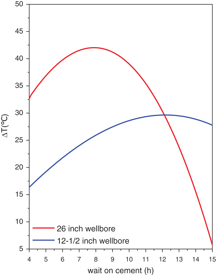
Figure 4: Temperature rise value for different borehole diameters and different waiting time
The figure above illustrates that for a 26-inch wellbore, the large annular volume and high cement content result in significant heat generation from hydration and a rapid temperature increase. This accelerates the hydration process in this section of the well and reduces the initial setting time of cement. As a result, after about 8 h of waiting on cement (WOC), the annular cement slurry system reaches its maximum heat release with a temperature increase of about 40°C. In contrast, for a 12-1/2″ wellbore with its smaller annular volume and lower cement content compared to a 26-inch wellbore, its heat release is less, and its temperature rise is slower. Consequently, its hydration process is slower than that of a 26″ wellbore. The peak heat release from hydration occurs after about 12 h WOC with an increase in peak temperature close to 30°C.
4 Field Implementation of Cementing in Shallow Formation of Deepwater
In a block in the South China Sea, a shallow well was drilled using a 20″ + 9-5/8″ composite casing structure. The well was cemented in sections to seal off the upper soft formations. A fiber optic temperature sensor was attached to the outer wall of the casing to monitor real-time temperature changes in the wellbore during casing running and cementing. Fig. 5 shows the wellbore structure after casing running and cementing.
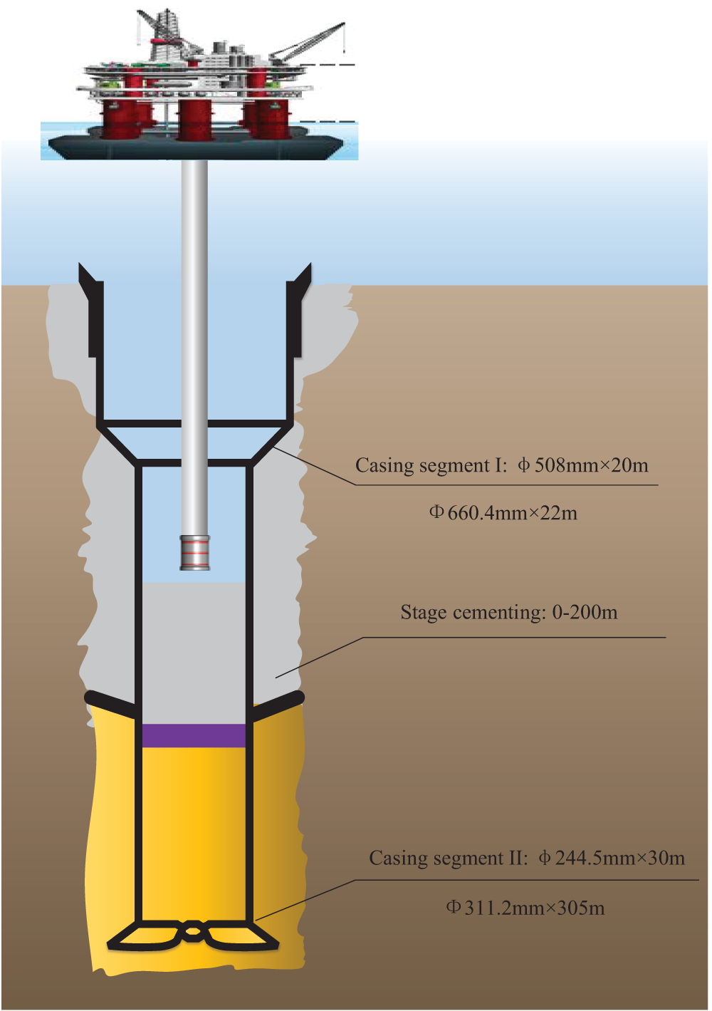
Figure 5: Wellbore structure after pipe string is running in
Once the casing was run to the designated depth, real-time temperature data from the formations were recorded. Fig. 6 shows the temperature changes detected by the sensor from before cementing began until after waiting on cement (WOC) was completed.
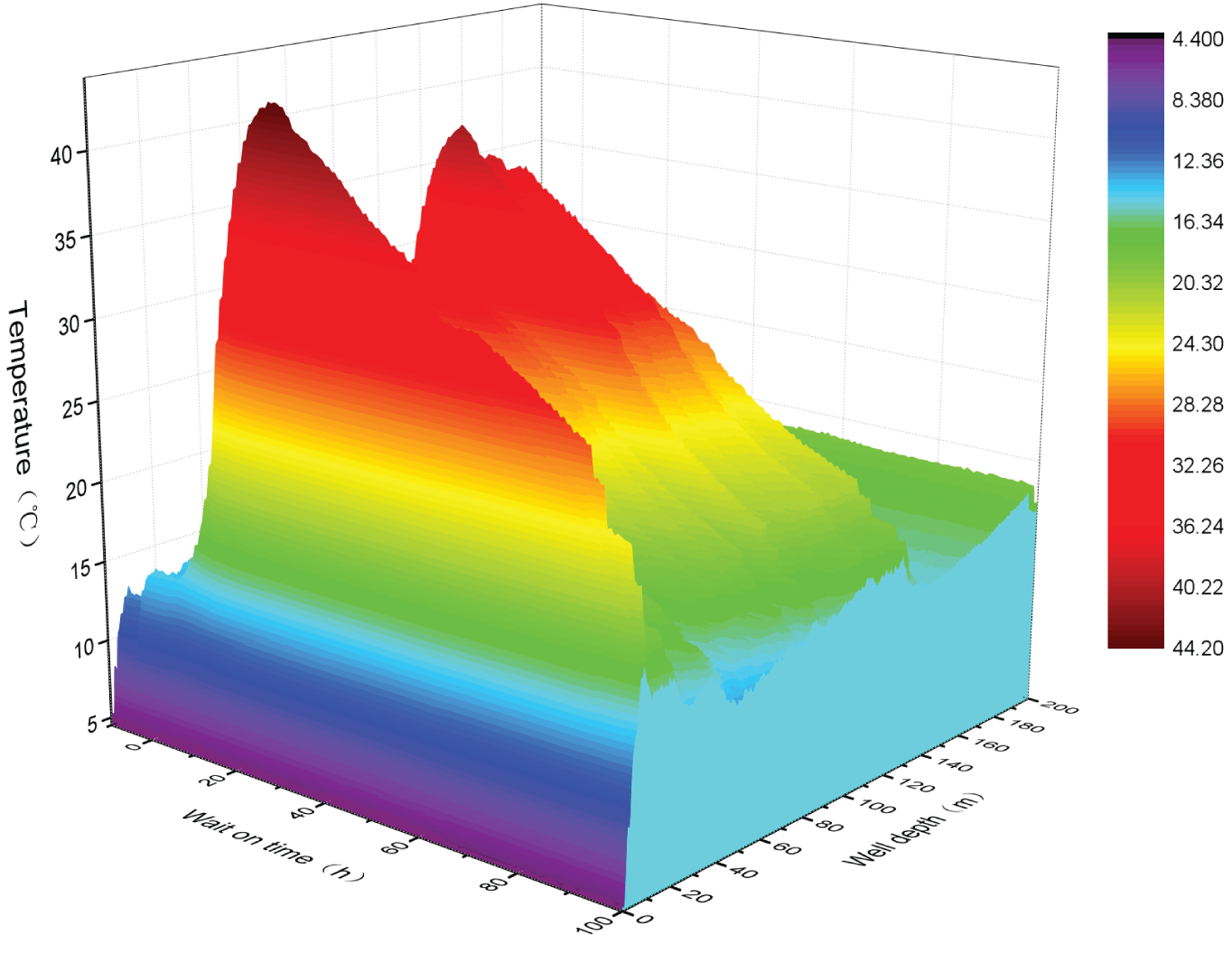
Figure 6: Wellbore temperature during waiting on cementing
Fig. 7 separately plots temperature changes over time at characteristic points near the wellhead, in the middle of the cemented section and near the bottom of the cemented section.
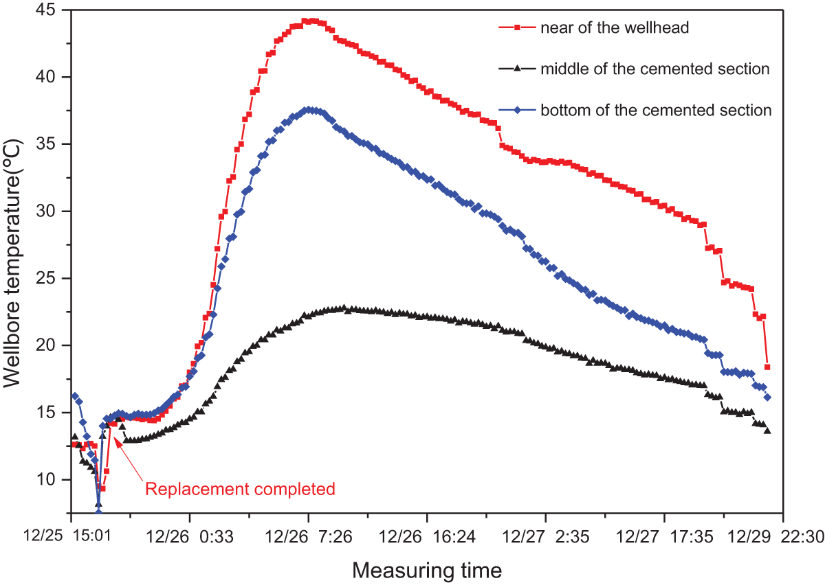
Figure 7: Temperature at characteristic points of wellbore
After cementing, Figs. 6 and 7 show the temperature changes in the wellbore. During cementing, the cement slurry passes through cold seawater and because the induction period is short (usually several tens of minutes), at this time, the cement slurry is still being injected into the wellbore from the platform via a cementing manifold and through about 1200 m of water depth. As a result, this stage of temperature change is not reflected in the figure above. After the induction period ends, the fluid enters a slow heat release phase which is reflected in the wellbore temperature curve after quantitative displacement is completed. During this period, there is little change in the slope of the temperature change curve which mainly reflects the induction period of cement hydration. The induction period is short and immediately followed by an acceleration period during which wellbore temperature increases rapidly with peak temperatures reaching nearly 45°C. This is the main heat release stage for cement in the wellbore. As described in analysis of cement hydration mechanism, this stage also marks the end of fluidity for cement slurry and beginning of transition to solid cement stone. If hydrates are present in cemented section, then during this process hydrate reservoir will decompose releasing large amounts of methane gas causing cracks or channels on outer wall of unconsolidated cement stone compromising wellbore integrity. About 10 h after WOC hydration reaction begins to weaken continuously as hydration enters deceleration phase with sufficient strength formed to withstand external loads and seal off lower formations.
By comparing the above figure with simulated data from the heat release model for cement hydration, there is a high degree of agreement. This proves that the heat release model for cement hydration can accurately reflect temperature changes in the wellbore during the cementing process. This model can be used to evaluate the hydration process during cementing and provide theoretical support for determining the setting time for slurry and heat release from hydration during later production development.
Cementing is a crucial step in maintaining the integrity of the wellbore. It plays a significant role in stabilizing the wellbore, securing the casing, and extending the production life of oil and gas wells, particularly in the development of natural gas hydrates in marine environments. The quality of cementing directly impacts the feasibility of depressurization production. However, the hydration heat release of cement slurry can adversely affect the stability of hydrates in the near-wellbore formation, promote hydrate decomposition, and allow the generated free gas and water enter to the well, thereby directly altering the solidification performance of the cement slurry, and compromising the mechanical properties of the cement sheath. The hydration heat release model presented in this article also indicates that the maximum temperature during the hydration process is nearly 45°C, which will have a profoundly adverse impact on the development of deep-water hydrates. Therefore, during the cementing process for deep and shallow formations, it is imperative to develop a corresponding cement slurry system that exhibits low hydration heat release intensity. This ensures efficient and safe exploitation of oil and gas resources beneath the hydrate layer, all while preserving the stability of the hydrates.
(1) During cementing in shallow formations of deep water, the wellbore temperature changes due to two main factors: the displacement of cement slurry and the heat release from cement hydration. The temperature of the cement slurry is low when pumped into the wellbore because it exchanges heat with seawater. As a result, it has little effect on the wellbore temperature.
(2) During the acceleration period, the temperature of cement hydration increases rapidly and has a significant impact on wellbore temperature. The hydration temperature model is consistent with field data and shows that the temperature peaks after 8–12 h of setting. In a 26″ wellbore, the temperature rises more than 40°C while in 12-1/4″ wellbore 30°C.
(3) External factors such as wellbore enlargement and cement additives can cause slight differences between the peak temperature time predicted by the model and that observed in field data.
Acknowledgement: The authors would like to thank the reviewers for their many constructive suggestions and comments that helped improve the quality of the paper.
Funding Statement: The authors gratefully acknowledge the financial support from Science and Technology Projects in Guangzhou (Grant number: No. 2023A04J0306). This research is also supported by China Geological Survey (Grant number: No. DD20230066), High-Tech Ship Research Project of Ministry of Industry and Information (Grant number: CJ05N20).
Author Contributions: Study’s planning, ideas, Jing Li; informational and data analysis, Bo Ning; literature evaluation, Bin Li; writing—review and editing, Jing Li, Dezhi Qiu. All authors reviewed the results and approved the final version of the manuscript.
Availability of Data and Materials: All data underlying the results are available as part of the article and no additional source data are required.
Ethics Approval: Not applicable.
Conflicts of Interest: The authors declare no conflicts of interest to report regarding the present study.
References
1. Johnson CR, Shindgikar ND, Beurel MM. Overcoming environmental and technical challenges for well cementing: a global perspective. SPE Product Operat. 2017;32(1):12–27. doi:10.2118/172792-PA. [Google Scholar] [CrossRef]
2. Kondori J, Zendehboudi S, Hossain ME. A review on simulation of methane production from gas hydrate reservoirs: molecular dynamics prospective. J Pet Sci Eng. 2017;159:754–72. doi:10.1016/j.petrol.2017.09.073. [Google Scholar] [CrossRef]
3. Demirbas A. Methane hydrates as potential energy resource: part 1-importance, resource and recovery facilities. Energy Convers Manag. 2010;51(7):1547–61. doi:10.1016/j.enconman.2010.02.013. [Google Scholar] [CrossRef]
4. Paull CK, Brewer PG, Ussler W, Peltzer ET, Rehder G, Clague D. An experiment demonstrating that marine slumping is a mechanism to transfer methane from seafloor gas-hydrate deposits into the upper ocean and atmosphere. Geo-Marine Lett. 2002;22:198–203. doi:10.1007/s00367-002-0113-y. [Google Scholar] [CrossRef]
5. Kareem MK, Abed WM, Dawood HK. Numerical simulation of hydrothermal behavior in a concentric curved annular tube. Heat Transfer. 2020;49(5):2494–520. doi:10.1002/htj.v49.5. [Google Scholar] [CrossRef]
6. Andreassen K, Hubbard A, Winsborrow M, Patton H, Vadakkepuliyambatta S, Faverola A, et al. Massive blowout craters formed by hydrate-controlled methane expulsion from the Arctic seafloor. Science. 2017;356(6341):948–53. doi:10.1126/science.aal4500. [Google Scholar] [CrossRef]
7. Weninger B, Schulting R, Bradtmöller M, Clare L, Collard M, Edinborough K, et al. The catastrophic final flooding of Doggerland by the Storegga Slide tsunami. Doc Praehistor. 2008;35:1–24. doi:10.4312/dp.35.1. [Google Scholar] [CrossRef]
8. Zeng Y, Lu P, Zhou S, Sang L, Liu R, Tao Q. A new prediction model for hydrostatic pressure reduction of anti-gas channeling cement slurry based on large-scale physical modeling experiments. J Pet Sci Eng. 2019;172:259–68. doi:10.1016/j.petrol.2018.09.035. [Google Scholar] [CrossRef]
9. Liu TL, Zheng SJ, Wang R, Sun JX, Jiang GS, Zhang L, et al. Negative effect of cementing slurry invasion on gas hydrate stability around borehole wall. Acta Petrolei Sinica. 2018;39(8):937–46. [Google Scholar]
10. Zou P, Huang Z, Tong Y, Tan L, Li R, Wei K, et al. Experimental evaluation of the mechanical properties of cement sheath under high-temperature conditions. Fluid Dynam Mater Process. 2022;18(3):689–99. doi:10.32604/fdmp.2022.019470. [Google Scholar] [CrossRef]
11. Cooke CE, Kluck MP, Medrano R. Annular pressure and temperature measurements diagnose cementing operations. J Pet Technol. 1984;36(12):2181–6. doi:10.2118/11416-PA. [Google Scholar] [CrossRef]
12. Lv K, Huang Z, Ling X, Xia X. Analysis of the weight loss of high temperature cement slurry. Fluid Dynam Mater Process. 2022;18(5):1307–18. doi:10.32604/fdmp.2022.020294. [Google Scholar] [CrossRef]
13. Jing J, Shan H, Zhu X, Huangpu Y, Tian Y. Wellbore temperature and pressure calculation of offshore gas well based on gas-liquid separated flow model. Processes. 2022;10(10):2043. doi:10.3390/pr10102043. [Google Scholar] [CrossRef]
14. Zhao X, Yang N, Liang H, Wei M, Ma B, Qiu D. The wellbore temperature and pressure behavior during the flow testing of ultra-deepwater gas wells. Fluid Dynam Mater Process. 2024;20(11):2523–40. doi:10.32604/fdmp.2024.052766. [Google Scholar] [CrossRef]
15. Duan X, Zuo J, Li J, Tian Y, Zhu C, Gong L. Prediction of gas hydrate formation in the wellbore. Energies. 2023;16(14):5579. doi:10.3390/en16145579. [Google Scholar] [CrossRef]
16. Jia F, Yao Y, Wang J. Influence and mechanism research of hydration heat inhibitor on low-heat portland cement. Front Mater. 2021;8:697380. doi:10.3389/fmats.2021.697380. [Google Scholar] [CrossRef]
17. Yang R, Sharp JH. Hydration characteristics of Portland cement after heat curing: I, degree of hydration of the anhydrous cement phases. J Am Ceram Soc. 2001;84(3):608–14. doi:10.1111/jace.2001.84.issue-3. [Google Scholar] [CrossRef]
18. Swaddiwudhipong S, Chen D, Zhang MH. Simulation of the exothermic hydration process of Portland cement. Adv Cem Res. 2002;14(2):61–9. doi:10.1680/adcr.2002.14.2.61. [Google Scholar] [CrossRef]
19. Lavagna L, Nisticò R. An insight into the chemistry of cement—A review. Appl Sci. 2022;13(1):203. doi:10.3390/app13010203. [Google Scholar] [CrossRef]
20. He SM, Yin C, Xu BH, Chi J, Song ZC. Mathematical model of determining borehole circulating temperatures in cementing and drilling processes. Nat Gas Indus. 2002;22(1):42–5. [Google Scholar]
21. Saedi AQ, Flori RE, Kabir CS. New analytical solutions of wellbore fluid temperature profiles during drilling, circulating, and cementing operations. J Pet Sci Eng. 2018;170:206–17. doi:10.1016/j.petrol.2018.06.027. [Google Scholar] [CrossRef]
22. Kutasov IM, Eppelbaum LV. Wellbore and formation temperatures during drilling, cementing of casing and shut. In: Proceedings of the World Geothermal Congress, 2015; p. 19–25. [Google Scholar]
23. Zhang R, Frigaard IA. Primary cementing of vertical wells: displacement and dispersion effects in narrow eccentric annuli. J Fluid Mech. 2022;947:A32. doi:10.1017/jfm.2022.626. [Google Scholar] [CrossRef]
24. Zhang R, Frigaard IA. Primary cementing of vertical wells: displacement and dispersion effects in narrow eccentric annuli. Part 2. Flow behaviour and classification. J Fluid Mech. 2023;972:A38. doi:10.1017/jfm.2023.697. [Google Scholar] [CrossRef]
25. Zhang FJ. Hydration, hardening and properties of class g oil well cement. Hangzhou, China: Zhejiang University; 2001. [Google Scholar]
26. Kutasov IM, Eppelbaum L. Cementing of casing—Temperature increase at cement hydration. In: 2013 Stanford Geothermal Workshop; 2013. [Google Scholar]
27. Kutasov IM. Dimensionless temperatures at the wall of an infinitely long, variable-rate, cylindrical heat source. Geothermics. 2007;36(3):223–9. doi:10.1016/j.geothermics.2007.03.004. [Google Scholar] [CrossRef]
28. Dillenbeck RL, Heinold T, Rogers MJ, Mombourquette IG. The effect of cement heat of hydration on the maximum annular temperature of oil and gas wells. SPE Drill Complet. 2003;18(4):284–92. doi:10.2118/87326-PA. [Google Scholar] [CrossRef]
Cite This Article
 Copyright © 2024 The Author(s). Published by Tech Science Press.
This work is licensed under a Creative Commons Attribution 4.0 International License , which permits unrestricted use, distribution, and reproduction in any medium, provided the original work is properly cited.
 Downloads
 Citation Tools