
 Submit a Paper
 Propose a Special lssue
 Open Access
ARTICLE

Ice-Induced Vibrational Response of Single-Pile Offshore Wind-Turbine Foundations
1 Department of Renewable Energy Engineering, PowerChina Huadong Engineering Corporation Limited, Hangzhou, 311122, China
2 School of Ocean Science and Technology, Dalian University of Technology, Panjin, 124221, China
3 Ningbo Institute of Dalian University of Technology, Ningbo, 315000, China
* Corresponding Author: Dayong Zhang. Email:
Fluid Dynamics & Materials Processing 2024, 20(3), 625-639. https://doi.org/10.32604/fdmp.2023.042128
Received 19 May 2023; Accepted 05 September 2023; Issue published 12 January 2024
 View Full Text
 Download PDF
Abstract
Important challenges must be addressed to make wind turbines sustainable renewable energy sources. A typical problem concerns the design of the foundation. If the pile diameter is larger than that of the jacket platform, traditional mechanical models cannot be used. In this study, relying on the seabed soil data of an offshore wind farm, the m-method and the equivalent embedded method are used to address the single-pile wind turbine foundation problem for different pile diameters. An approach to determine the equivalent pile length is also proposed accordingly. The results provide evidence for the effectiveness and reliability of the model based on the equivalent embedded method.Keywords
The development and application of offshore wind energy resources is vital for the increased utilization of renewable energy sources [1,2]. Due to long-term ice coating in winter, offshore wind turbine foundation structures are vulnerable to sea ice, typifying that the construction of large-scale offshore wind farms faces several technical challenges. Because of the large-scale development of offshore wind turbines, wind turbine foundations have larger pile diameters than jacket platforms. Therefore, the mechanical model established by the conventional six times pile diameter method is inapplicable to such large-diameter structures. Therefore, there is a current need to develop a suitably applicable method.
For single-pile foundations under ice-induced vibration, pile-soil interaction is still an important and difficult issue to investigate. Several researchers have performed extensive research on pile-soil interactions in pile foundation structures and the related theoretical models mainly include the continuous elastic dynamic model, finite element model, and Winkler foundation beam model [3]. Among them, the Winkler foundation beam model considers soil as an independent spring and damping to make the discretion of the whole pile-soil model possible.
Methods for analyzing pile-soil interaction characteristics based on numerical simulation could be divided into the m-method, p-y curve method [4], equivalent embedded method, six-spring method, etc. [5], through which researchers have simulated structural dynamic characteristics. Nogmai et al. [6] found negative correlations among embedded depth, pile diameter, and cohesion and proposed a fitting equation. Based on the sub-plastic constitutive model, Lu et al. [7] numerically analyzed the vertical and horizontal combined loading of piles in sandy soils and proposed a new p-y curve model which was applicable to such combined loading conditions. Using the m-method and p-y curve method, Zhou et al. [8] performed static analysis and comparison of the overall structures of offshore turbines with single pile foundations. Using the m-method, Wang et al. [9] studied the dynamic and static transformations of m value in model tests and developed a new lateral dynamic load test method for offshore pile foundations.
Taghavi et al. [10] showed the existence of axial force and lateral soil resistance in pile-soil interactions and a coupling relationship between the two. Khodair et al. [11] developed a finite element numerical model for pile-soil interactions, analyzed the calculation models of different pile diameters and depths under horizontal load, and performed data regression. Dicleli [12] adopted the pushover analysis method and determined the equivalent pile length of an abutment foundation. Chen [13] reviewed several methods for the determination of equivalent pile length and discussed their limitations. Doran et al. [14] investigated the lateral bearing capacity of wharf structures considering soil-pile interactions under various soil conditions.
Although quite mature and well-described in several specifications, the equivalent embedded method still shows difficulty in determining equivalent lengths of large-diameter piles. Therefore, in this study, the m-method pile-soil model was adopted for the calculation of structural mud surface stiffness, the results of which supported the prediction of the relationship between equivalent length and pile diameter. In addition, the equivalent embedded method was applied for modeling to finally analyze ice-induced vibration responses of large-diameter single-pile wind turbine foundations.
2 Equivalent Embedded Method and Pile-Soil Interaction Model
Two mechanical models have been developed for the study of pile-supported offshore structures and their causes of failure. First, the main failure mode of the structures was determined to be caused by the loss of foundation soil-bearing capacity. In this case, the analysis of structural safety performance mainly considered foundation soil status change; therefore, a detailed simulation was necessary for the pile-soil interaction process. Second, the main failure mode of the structures was attributed to function failure under excessive vibration acceleration response when the superstructure was subjected to load or structural fatigue failure under long-term cyclic load. Under such conditions, the analysis of structural safety performance mainly considered superstructure status change; therefore, the pile foundation model could be developed according to the equivalent embedded method. In the basic anti-icing design of the structure, the main focus was on fan system vibrations, such as function failure of key equipment in vibration acceleration response, fatigue failure at stress concentration, etc. Due to these properties, the equivalent embedded method has been extensively applied for the modeling of offshore pile foundation structures such as jacket platforms.
During the analysis of the mechanical characteristics of marine structures, the “six times pile diameter method” was used for imposing fixed constraints on the structure at six times pile diameter below the mud surface; however, the large single-pile wind power foundation had a pile diameter far exceeding that of the jacket platform and therefore, the finite element model developed by the traditional six times pile diameter method had uncertain reliability.
2.1 Analysis of the Pile Characteristics of Large Single-Pile Wind Power Foundations
Offshore structures in iced areas are mainly exposed to horizontal loads, such as wind load and ice load. Offshore pile foundation structures derive resistance to horizontal loads from soil resistance generated by foundation soil on the pile side. The pile undergoes lateral deformation under lateral load, resulting in soil compression deformation on the pile side, while the deformed soil develops soil resistance to pile deformation. For structures under lateral loads at the pile top, the ratios of pile depth to pile diameter were different, resulting in varying deformations of pile side soil and pile body. Accordingly, piles can be divided into two categories [15–17]:
(1) For large pile diameters, pile depth was shallow, and the stiffness of pile bending was obviously higher than that of pile foundation soil; such a pile is referred to as a rigid short pile. Under top horizontal loads, the pile body rotates around a certain point, as illustrated in Fig. 1.

Figure 1: Deformation of a rigid short pile
(2) For small pile diameters, pile depth was deep, and bending stiffness was obviously smaller than pile foundation soil stiffness; such piles are called flexible long piles. Under the action of horizontal force, flexural deformation occurred on the pile body, while the lower parts basically had no deformation, as illustrated in Fig. 2.

Figure 2: Deformation of a flexible long pile
Large single-pile wind power foundations have large diameters and great bending section stiffness. However, according to the provisions on the burial depth of single-pile foundations reported in “Design Code for Wind Turbine Foundation in Offshore Wind Farm Engineering”, the pile deformation of large single-pile wind power foundations could be defined under transverse loads [18,19]. Large single-pile wind power foundations belong to flexible long piles. When subjected to a lateral force at the top, this type of pile will have a point under the soil where the rotation angle and horizontal displacement are both zero [20,21]. The pile above this point undergoes flexural deformation to resist the transverse load at the top. In establishing a finite element model for such structures, the equivalent embedded method was adopted for simplification, with the schematic diagram of this method illustrated in Fig. 3.

Figure 3: Schematic diagram of equivalent embedding method
The figure on the right in Fig. 3 represents the pile model considering pile-soil interaction. Under pile deformation, both the side and bottom of the pile are subjected to the resistance of the foundation soil. The figure on the left shows the pile model developed based on the equivalent embedded method. By eliminating the lower part of the pile without deformation and simplifying its upper deformed part, the original complicated pile-soil model was transformed into a simple model similar to a cantilever beam.
2.2 Determination of Equivalent Pile Length
This section discusses the determination of the equivalent embedded point of large-diameter single-pile wind turbine foundations through finite element numerical simulations. A single-pile wind turbine foundation in the Bohai Sea with pile diameter 7.5 m, pile depth 60 m, a tower height of 112 m, and a tower diameter of 7.0 m at maximum and 5.2 m at minimum was adopted as the research object. The whole structure was a cone with a large bottom and a small top, which is a typical large single-pile wind turbine foundation structure. The geological data of the sea area are summarized in Table 1, presenting typical geological conditions for the construction of offshore wind turbines.

First, a finite element model considering pile-soil coupling was developed according to the m-method. Mud surface stiffness was calculated to provide a reference for the determination of the position of an equivalent embedded point in the equivalent embedded method. At the same time, a finite element model was developed according to the equivalent embedded method. The characteristic mechanical parameters of the two models, such as inherent frequency and horizontal stiffness, were compared. Then, to calculate the equivalent embedded point depth for various pile diameters, the pile diameter was changed while other parameters remained unchanged through repeated steps. Finally, the mathematical relationship between the structure width and embedded point depth was established, as shown in Fig. 4.

Figure 4: Workflow chart
2.2.1 Introduction of the Finite Element Model
Horizontally loaded pile-soil interaction was analyzed by the p-y curve method, limit state analysis method, and elastic foundation reaction method. For offshore wind turbine structures, the simulation of the ultimate bearing state of pile foundation and inspection of pile structure safety under normal conditions are required. The elastic foundation reaction method is simple in form, supports pile-soil reaction analysis of the structure under normal conditions, and is recommended for the pile-soil reaction analysis of offshore wind turbine structures. Among the existing elastic foundation reaction methods, the m-method is the most commonly adopted one. In “Port Pile Foundation Code”, a detailed description has been given for the simulation of pile-soil reaction by the m-method. The m-method assumes that the resistance coefficient of the horizontal foundation increases linearly with depth [22], i.e.,
where K is the horizontal foundation resistance coefficient of the foundation soil, kN⋅m−3, and m is the proportionality factor of the horizontal resistance coefficient of the foundation soil in depth. This factor can be determined by a horizontal static load test on the pile foundation. If test pile data is unavailable, it can be obtained by consulting the m value reference table, with the parameters summarized in Table 2. z is the depth of the calculation point.

The horizontal spring stiffness of the simulated soil layer was calculated by Eq. (2):
where B0 is the calculated width of the pile. For circular pile sections, B0 = 0.9 (D + 1), in which D is the round pile diameter and h is the thickness of the taken soil layer.
The wind turbine model was developed using ANSYS software, the mass of the upper unit adopted the MASS21 unit, and the tower adopted the BEAM188 unit. By subjecting the structure to ice forces with different mesh sizes, an analysis was conducted to study the variation of the maximum stress values and displacement response of the structure under the influence of ice forces (F = 100 kN) as the mesh size changes. The analysis results are presented in Table 3. It can be observed from the results in the table that significant changes occur when the mesh size exceeds 0.01 m. Therefore, the mesh size of the finite element model was set to 0.01 m to meet the calculation accuracy and efficiency.

When using the m-method for the introduction of the pile-soil model, soil springs are set with a group of springs along the x and y directions and arranged at certain intervals. One side of the springs was connected to the pile and fixed constraints were applied to the other side. The established model is illustrated in Fig. 5.

Figure 5: The m-method pile-soil model
An equivalent pile model with a simple form can be considered as a cantilever beam with one fixed end. The key was to determine the equivalent pile length, i.e., fixed-point location. When establishing an offshore platform model, six times the pile diameter can be adopted as the equivalent pile length [23]. However, when applied to large offshore single-pile wind turbine foundations with significantly increased pile diameters, this assumption underestimates mud surface stiffness, resulting in the loss of the reliability of calculation results. However, based on this assumption, a reliable equivalent pile model was developed by continuously elevating the position of the embedded point. Finally, the equivalent pile length of the large single-pile wind turbine foundation was found to be 16 m and the model was established, as illustrated in Fig. 6.
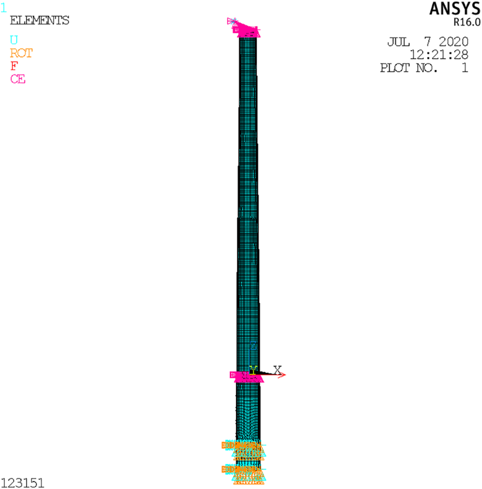
Figure 6: Equivalent pile model
2.2.2 Determination of the Equivalent Pile Length for Different Pile Diameters
To derive a rapid method for obtaining the positions of embedded points, the earlier described method was applied for the determination of the equivalent pile length for different pile diameters. When using ANSYS software for the simulation of pile-soil interactions based on the m-method, combin14 unit was applied to set springs along x and y horizontal directions at the middle point of each soil layer. The calculation point depth was determined by the middle point of the soil layer, with pile diameters of 3, 4, 5, 6, 7, 8, and 9 m.
The horizontal stiffness at the mud surface calculated by the m-method was applied as the basis for the determination of equivalent pile length in the equivalent embedded method. The horizontal stiffness of the mud surface in each structure is given in Table 4.

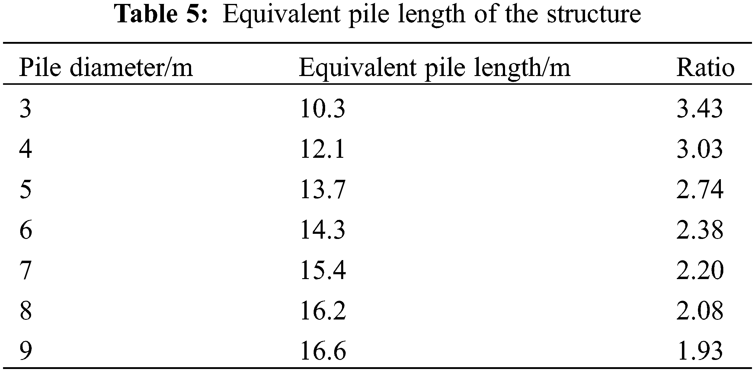
Mud surface stiffness was calculated and applied as a reference for the determination of the equivalent pile length of the model. The ratio of equivalent pile length to pile diameter was defined as N, and the results are summarized in Table 5.
The finite element model was developed by the equivalent embedded method, and the mud surface stiffness values of the equivalent pile model and m-method were compared, as illustrated in Fig. 7.

Figure 7: Comparison of the horizontal stiffness values of the mud surface between the two models
Comparison of the data presented in Fig. 7 showed that the equivalent pile model and the m-method pile-soil model had a difference within 5% in mud surface stiffness. Therefore, it could be adjudged that the equivalent pile model developed for each pile diameter was equivalent to the m-method pile-soil model. The pile diameter D and ratio N summarized in Table 4 were numerically fitted by a power function, with the fitting results illustrated in Fig. 8.

Figure 8: Fitting results of pile diameter D and ratio N
The reliability value of this fitting was 0.99, which proved the accuracy of the developed model; therefore, the reliability of the fitting results was basically guaranteed. Hence, the numerical relationship between the pile diameter D and ratio N was stated as:
3 Ice-Induced Vibration Response Analysis of Wind Turbine Foundations
In engineering, basic anti-icing design for marine equipment should consider structural safety check, fatigue analysis, etc., which require high accuracy in evaluating the mechanical characteristics of the model, such as horizontal stiffness and inherent frequency. In addition, the interaction between sea ice and the offshore structure involves a dynamic process, and steady-state [24] vibration of the structure might occur due to dynamic ice force, which poses a non-negligible problem in the basic anti-icing design of offshore structures. In this section, modal, static ice force response, and transient response analyses were performed using the finite element model developed by the m-method and equivalent embedded method, and the obtained results were compared. The first two natural vibration frequencies and horizontal stiffness at the mud surface were calculated and the results are presented in Table 6.

The comparison showed that the structural model developed based on the equivalent embedded method had similar mechanical properties to that based on the m-method, although there were slight deviations. The mud surface stiffness of the equivalent pile model was slightly smaller than the design value, while the inherent frequency was slightly greater than the design value. In accordance with the related general structural dynamics theory, the inherent frequency of the structure was positively correlated with stiffness. Therefore, although the equivalent pile model did not achieve complete accuracy for the two parameters, with there being a small deviation, the results of the analysis were barely affected.
In accordance with the “China Sea Ice Conditions and Application Specifications” [25], ice conditions were adopted for the sea area where this structure was located, as summarized in Table 7, and structural response analysis was performed for the two mechanical models under extreme static ice force, as shown in Fig. 9. Under static ice force, the large single-pile wind power structures displayed similar stress distributions, with maximum stress values being 3.3 and 4.1 MPa.

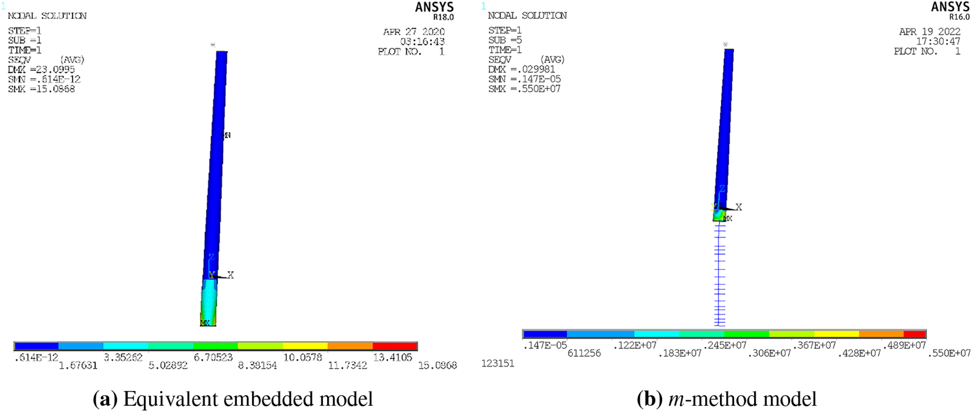
Figure 9: Stress nephograms of the two models
Deformation and stress were calculated for the two key positions, i.e., tower top and ice force location, as given in Table 8. The two models had similar calculation results at key positions.

Based on the triangular wave time-domain function [26], a steady-state ice force model with 0.3 m ice thickness was developed. As illustrated in Fig. 10, Fmax is the extreme value of ice force, ΔF = qFmax in which the value of q ranged from 0.1 to 0.5 and was assumed to be 0.4 in this study. Fmean is the mean value of ice force, T is the ice force period, and the value of α ranged from 0.6 to 0.9 and was assumed to be 0.8 in this work. Transient dynamics analysis was performed on the two mechanical models of large single-pile offshore wind turbine structures and response time histories were determined for key positions. Fig. 10 illustrates the vibration displacement, acceleration response time history diagram of ice force location, and tower top in the equivalent pile model.

Figure 10: Model of steady-state ice loading
As shown in Fig. 11, both displacement and acceleration response time histories of tower top and displacement response time history of force location displayed amplification of response extremum that eventually tended to stabilize. The obtained vibration response results were in line with the characteristics of steady-state ice response. The response extremums of the m-method and equivalent embedded method were compared and summarized as given in Table 9.


Figure 11: Ice vibration responses of the equivalent pile model

When ice-induced steady-state vibration was triggered under ice conditions, the m-method and equivalent embedded method were slightly different and varied within 10% in calculation results. By comparing the equivalent embedded method and m-method pile-soil models in terms of structural mechanical properties, static response, and transient response results, it was concluded that the proposed model with equivalent pile length could be well applied to basic anti-icing design and analysis of large-diameter single-pile offshore wind turbine infrastructure.
1) Based on the seabed soil conditions of a wind farm in Bohai Sea, a mechanical model of a single-pile wind turbine’s foundation was developed in this work based on the m-method and equivalent embedded method. Calculations revealed that the equivalent pile model and m-method had a difference of within 5% in mud surface stiffness. Therefore, this proves that the equivalent pile model developed for each pile diameter is equivalent to the m-method pile-soil model.
2) Model analysis, static ice force response analysis, and transient response analysis were performed on the finite element model developed by the m-method and equivalent embedded method. The results show that when ice-induced steady-state vibration is triggered, the m-method and equivalent embedded method have slight differences of within 10% in calculation results. A comparison of the obtained results shows that the model with equivalent pile length could be well applied to basic anti-icing design and analysis of large-diameter single-pile offshore wind turbine infrastructure.
Acknowledgement: We would like to thank the reviewers for the many useful comments.
Funding Statement: This study was supported by the National Natural Science Foundation of China (52071055), and the Fundamental Research Funds for the Central Universities (Grant No. DUT22QN237).
Author Contributions: Zhoujie Zhu: Investigation, Software, Data curation, Editing. Gang Wang & Qingquan Liu: Investigation, Editing. Guojun Wang & Rui Dong: Software, Editing. Dayong Zhang: Supervision, Review, Methodology. All authors reviewed the results and approved the final version of the manuscript.
Availability of Data and Materials: The data that support the findings of this study are available from the corresponding author upon reasonable request.
Conflicts of Interest: The authors declare that they have no conflicts of interest to report regarding the present study.
References
1. Robertson, B., Dunkle, G., Gadasi, J., Garcia-Medina, G. (2021). Holistic marine energy resource assessments: A wave and offshore wind perspective of metocean conditions. Renewable Energy, 170, 286–301. [Google Scholar]
2. Soares, C., Bhattacharjee, J., Karamakar, D. (2014). Overview and prospects for development of wave and offshore wind energy. Brodogradnja, 65(2), 87–109. [Google Scholar]
3. Wang, H. (2020). Lateral behavior of offshore monopile and bucket foundations in sand (Ph.D. Thesis). Zhejiang University, China. [Google Scholar]
4. Naggar, M. H. E., Bentley, K. J. (2000). Dynamic analysis for laterally loaded piles and dynamic p-y curves. Canadian Geotechnical Journal, 37(6), 1166–1183. [Google Scholar]
5. Wang, H. R., Ma, T. T., Cai, W. Z. (2022). Pile-soil effect study on dynamic characteristics of jacket offshore wind turbine. Building Structure, 52(S1), 2468–2473. [Google Scholar]
6. Nogmai, T., Otnai, J., Konagai, K. (1992). Nonlinear soil-pile interaction model for dynamic lateral motion. Journal of Geotechnical Engineering, 118(1), 90–106. [Google Scholar]
7. Lu, W. J., Zhang, G. (2020). New p-y curve model considering vertical loading for piles of offshore wind turbine in sand. Ocean Engineering, 203, 107228. [Google Scholar]
8. Zhou, Q. Z., Chi, H. M., Wu, Y. X. (2018). Research on influence of different pile-soil models on offshore wind turbine monopile foundation design. Building Structure, 48(S2), 834–837. [Google Scholar]
9. Wang, J. P., Su, J. B., Wu, F., Zhang, Z., Lv, Y. R. (2021). Lateral dynamic load tests of offshore piles based using the m-method. Ocean Engineering, 220, 108413. [Google Scholar]
10. Taghavi, A., McVay, M., Niraula, L., Davidson, M., Patil, A. (2020). Axial and lateral resistance coupling in the analysis of large-diameter drilled shafts. Engineering Structures, 206, 110160. [Google Scholar]
11. Khodair, Y., Abdel-Mohti, A. (2014). Numerical analysis of pile-soil interaction under axial and lateral loads. International Journal of Concrete Structures and Materials, 8(3), 239–249. [Google Scholar]
12. Dicleli, M. (2005). Integral abutment-backfill behavior on sand soil—Pushover analysis approach. Journal of Bridge Engineering, 10(3), 354. [Google Scholar]
13. Chen, Y. (1997). Assessment on pile effective lengths and their effects on design—I. Assessment. Computers & Structures, 62(2), 265–286. [Google Scholar]
14. Doran, B., Seckin, A. (2014). Soil-pile interaction effects in wharf structures under lateral loads. Structural Engineering & Mechanics, 51(2), 267–276. [Google Scholar]
15. Li, C. Y., Zhou, X. Q., Chen, M. C. (2019). Numerical modeling of medium length piles wharf under the geological condition of cemented sand. Journal of Waterway and Harbor, 40(2), 188–193. [Google Scholar]
16. Zeng, S. P., Leng, J., Ye, G. L. (2015). Numerical anslysis of stiffness degradation of a rigid short pile in clay under horizontal dynamic loads. China Earthquake Engineering Journal, 37(Suppl 2), 181–184. [Google Scholar]
17. Su, L., Wan, H. P., Dong, Y., Frangopol, D. M., Ling, X. Z. (2019). Seismic fragility assessment of large-scale pile-supported wharf structures considering soil-pile interaction. Engineering Structures, 186, 270–281. [Google Scholar]
18. NB/T (Energy Sector Standard of the People’s Republic of China) National Energy Administration (2018). NB/T 10105–2018, Code for design of wind turbine foundations for offshore wind power projects. https://www.dugen.com/p-25622.html [Google Scholar]
19. Passon, P., Branner, K. (2013). Load calculation methods for offshore wind turbine foundations. Ships and Offshore Structures, 9(9), 433–449. [Google Scholar]
20. Wang, K. H., Xie, X. Y. (2001). A study on dynamic stiffness based on continuous elastic model of pile. Journal of Building Structures, 2, 88–91. [Google Scholar]
21. Bozyigit, B. (2021). Seismic response of pile supported frames using the combination of dynamic stiffness approach and Galerkin’s method. Engineering Structures, 244, 112822. [Google Scholar]
22. JTS (Jiao Tong Standard) Water Transport Engineering (2018). JTS 167–2018, Design code for wharf structures. https://wtis.mot.gov.cn/syportalapply/sysnoticezl/indexzl [Google Scholar]
23. Fang, H. C. (1996). Engineering mechanics of offshore petroleum steel structure in ice zone—Evaluation of structural strength and safety reliability of offshore petroleum steel, pp. 80–85. China: China University of Petroleum Press. [Google Scholar]
24. Karna, T. (1994). Steady-state vibrations of offshore structures. Hydrotechnical Construction, 28(8), 446–453. [Google Scholar]
25. Q/HS (Qiye/Health and Safety) China National Offshore Oil Corporation (2002). Q/HSn 3000–2002, Regulations for offshore ice condition & application in China sea. https://www.docin.com/p-88601218.html [Google Scholar]
26. Karna, T., Izumiyama, K., Yue, Q. J., Qu, Y., Guo, F. W. et al. (2007). An upper bound model for self-excited vibrations. Proceedings of the 19th International Conference on Port and Ocean Engineering under Arctic Conditions, pp. 177–189. Dalian, China. [Google Scholar]
Cite This Article
 Copyright © 2024 The Author(s). Published by Tech Science Press.
This work is licensed under a Creative Commons Attribution 4.0 International License , which permits unrestricted use, distribution, and reproduction in any medium, provided the original work is properly cited.
 Downloads
 Citation Tools