
 Submit a Paper
 Propose a Special lssue
 Open Access
ARTICLE

Influence of Bottom Inclination on the Flow Structure in a Rotating Convective Layer
Laboratory of Turbulence, Institute of Continuous Media Mechanics UB RAS, Perm, 614013, Russia
* Corresponding Author: Andrei Sukhanovskii. Email:
(This article belongs to the Special Issue: Advanced Problems in Fluid Mechanics)
Fluid Dynamics & Materials Processing 2024, 20(4), 739-748. https://doi.org/10.32604/fdmp.2024.048092
Received 27 November 2023; Accepted 19 December 2023; Issue published 28 March 2024
 View Full Text
 Download PDF
Abstract
The formation of convective flows in a rotating cylindrical layer with an inclined bottom and free surface is studied. Convection is driven by localized cooling at the center of the upper free surface and by rim heating at the bottom near the sidewall. The horizontal temperature difference in a rotating layer leads to the formation of a convective flow with a complex structure. The mean meridional circulation, consisting of three cells, provides a strongly non-uniform differential rotation. As a result of the instability of the main cyclonic zonal flow, the train of baroclinic waves appears in the upper layer. The baroclinic waves provide most of the heat transfer in the middle radii and are responsible for strong temperature and velocity fluctuations. It is shown that the inclination of the bottom is a crucial factor for the structure of the convective cells and the dynamics of the baroclinic waves. The increase in the inclination angle leads to a significant increase in the energy of the waves. The obtained results may be important for heat and mass transfer in various geophysical and industrial systems, including transport of various additives and impurities in rotating crucibles, and crystallization processes.Keywords
The rotating convection covers a wide range of problems related to the science of materials, crystal growth, thermal engineering, meteorology, oceanography, geophysics, and astrophysics. The horizontal temperature difference in a rotating fluid layer results in the instability of the basic flow and transition to the baroclinic wave regime and further to the disordered behavior in the form of so-called ‘baroclinic chaos’, which provides an important form of chaotic transition in fluid dynamics [1]. This is of particular geophysical relevance to the problem of the large-scale circulation of the Earth and other terrestrial planets [2–6]. Also, the main features of this kind of instability are important to industrial processes, e.g., the Czochralski technique for the growth of crystals from the melt [7–11]. In the present study, we mainly focus on the geophysical aspects of the baroclinic waves in a rotating convective layer.
Laboratory analogs of atmospheric flows allow, on the basis of well reproducible experiments, to study the fundamental basis of complex dynamic processes, test existing hypotheses, find new effects, formulate topical problems, and build theoretical models [1,2]. The main laboratory model for mid-latitude circulation was developed in [12] and consists of a rotating annular vessel with three concentric cylinders, where the narrow gap of the outer annulus is filled with warm fluid, the inner cylinder is filled with cold fluid and the central part is the experimental chamber filled with water. This configuration has been successfully used for many years to study various aspects related to baroclinic wave formation in mid-latitudes [2]. Recent studies are focused on the influence of mechanical and thermal inhomogeneity on the baroclinic wave formation [13,14], and the generation of different waves in the barostrat instability experiment [15]. First laboratory studies of mid-latitude circulation in a frame of a polar amplification scenario [16,17] showed that a decrease in the meridional temperature difference slows down the eastward propagation of the jet stream and complexifies its structure. Laboratory models can be used to study extreme temperature fluctuations of the mid-latitude atmospheric circulation [18,19]. The use of vertical isothermal walls in the model [12] imposes a number of limitations [2]. An attempt to avoid the main limitations of the model [12] was made in [20], where the heat source was located at the periphery of the bottom and the disk cooler was located in the upper part of the central region of the cylindrical gap.
Another important factor is the geometry of the layer. In models [12] and [20], the aspect ratio (layer height to cylindrical gap width) was 1 and 0.65, respectively. In [21], a new laboratory model was implemented in which the rim heater is displaced from the sidewall and for a much smaller value of the aspect ratio a ≈ 0.09. The new laboratory model reproduces the main features of the global atmospheric circulation, namely, the anticyclonic flow at low latitudes, the cyclonic circulation in the region of middle and polar latitudes, the formation of large-scale baroclinic vortices, and the three meridional cells (analogs of Hadley, Ferrell, and polar cells). In [22], a comparative analysis of different configurations of laboratory atmospheric general circulation models is presented.
Strong variation of the Coriolis force (beta effect) in the real atmosphere leads to the formation of large-scale waves, usually called Rossby waves [1]. They are localized predominantly at low latitudes, but can propagate at higher latitudes as well, affecting the mid-latitude circulation and baroclinic waves. A flat horizontal bottom, typical of most laboratory models of the general circulation of the atmosphere, excludes the formation of Rossby waves, but modeling of the beta effect in laboratory conditions is possible using a sloping bottom.
This paper presents the first results of mathematical modeling in a setting approximating [21], for a larger layer thickness (a ≈ 0.17) and in the presence of a bottom slope modeling the beta effect.
The problem formulation is similar to experiments [21], which makes it possible to compare the results obtained by different approaches. The study was performed by direct numerical simulation of thermal convection in a rotating cylindrical layer filled with silicon oil (PMS-5) using the freely distributable computational fluid dynamics package OpenFOAM v2106. Fig. 1 shows a scheme of the computational domain.
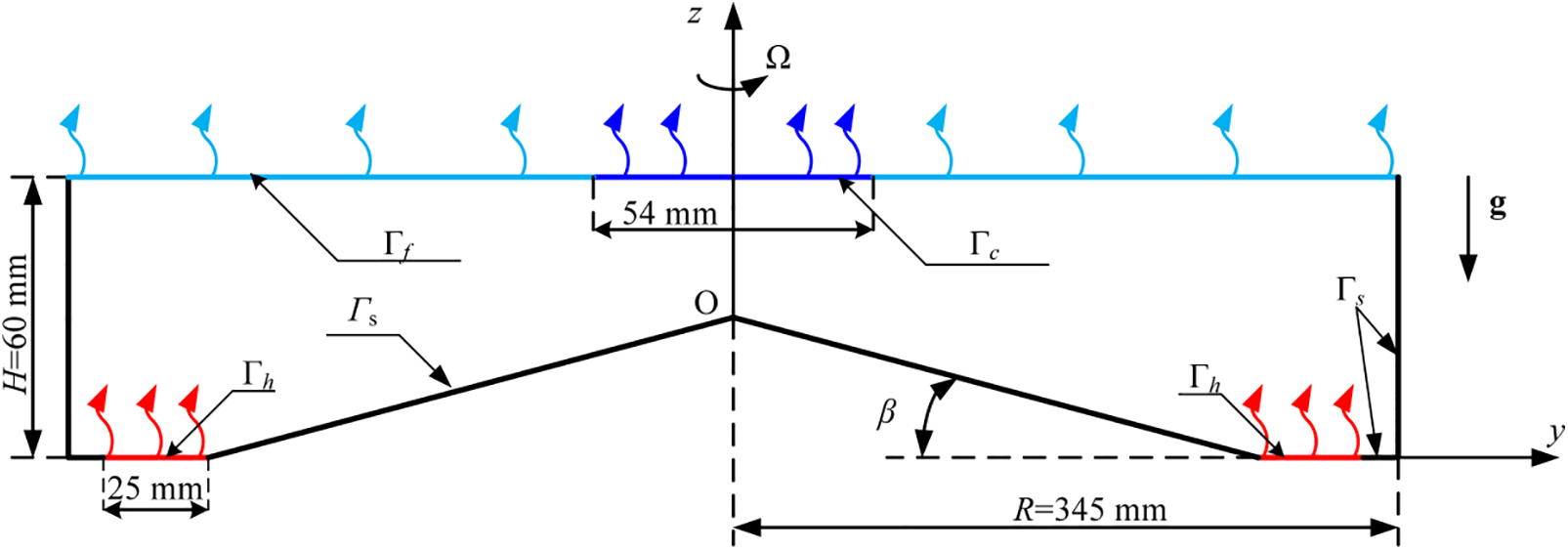
Figure 1: Scheme of the computational domain
The system of equations describing the motion of incompressible fluid in the rotating system in the Boussinesq approximation is as follows:
where
The computational uniform mesh is a multi-block structured mesh with a total number of control volumes of 2.8 million allows to resolve of boundary layers and small-scale convective structures [23]. Time integration was performed according to an implicit Euler scheme of second-order accuracy. The integration step was adaptive and the Courant-Friedrichs-Levy criterion did not exceed 0.4. For the discretization of convective and diffusive terms, a second-order approximation central difference scheme was used (in the case of OpenFoam this scheme is called Gauss linear). To solve the system of linear algebraic equations obtained after discretization of the equations, the bi-conjugate PBiCG gradient method with DILU preconditioner (for velocity and temperature) and the GAMG method for pressure were used.
The non-slip condition is applied to the sidewalls, the bottom (including the heating area) and the cooler (at the upper boundary):
At the upper surface (excluding the cooling area), there is a free-slip boundary condition:
The sidewalls and the bottom (except the heating area) are adiabatic:
The heating at the bottom and cooling at the upper surface is realized by constant heat flux:
where
As non-dimensional governing parameters, following [11], we use the thermal Rossby number RoT, the Taylor number Ta, and the Ekman number E:
where
One of the most interesting applications of the system under consideration is the modeling of the general circulation of the atmosphere. The laboratory analogue of the general circulation of the atmosphere in the dishpan configuration is a rotating liquid layer with an aspect ratio noticeably less than unity, with a localized rim heater located at the bottom periphery and a disk-shaped cooler placed in the central part, at the upper boundary of the fluid layer [21]. The rim heater simulates heating in the equatorial region and cooler, cooling in the polar region. The heater is specifically offset from the sidewall to minimize its influence, through interaction with non-slip boundary, on the formation of flows. In addition, the displacement of the heating area from the side wall leads to the formation of zonal flows (analogs of east and west winds) that are typical for the equatorial region. Due to the transfer of angular momentum, the radial flow directed to the periphery forms an anticyclonic circulation (opposite to the rotation of the model), and the convergent flow (directed to the center) leads to the appearance of intense cyclonic motion. A detailed description of the laboratory model can be found in [21,22].
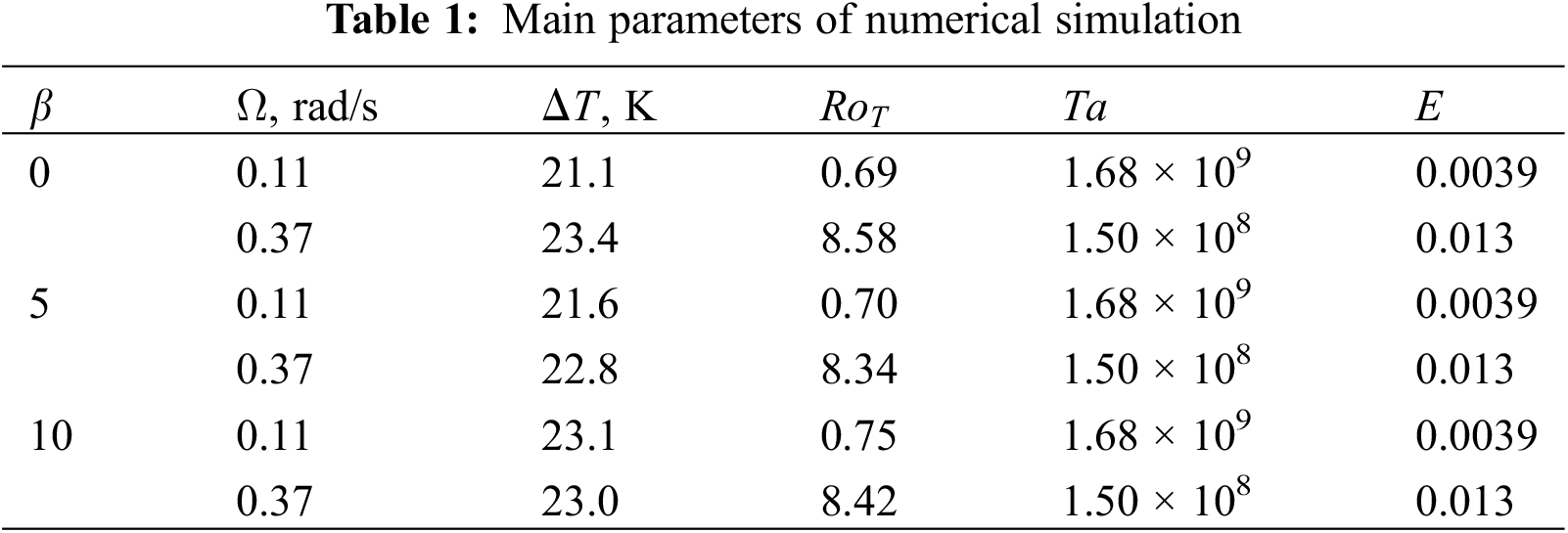
In the present work, we focused on studying the role of bottom inclination on flow formation. The magnitude of inclination in the shallow layer is restricted by its depth, so in order to consider a relatively large inclination angle (up to 10o) we increase the layer depth to 60 mm, and the aspect ratio to a ≈ 0.17 (in [21], a ≈ 0.17). It can be expected that changes in the geometry and interactions of different types of waves can lead to significant variations in the flow structure and temperature distribution. We limit ourselves to the consideration of the average characteristics of the flows for two particular regimes. The first one is for a relatively slow rotation (Ω = 0.11, rad/s), at which in case of the horizontal bottom the basic flow is stable and baroclinic waves do not appear. The second regime for a fast rotation (Ω = 0.37, rad/s) corresponds to an “atmospheric” regime that resembles the structure of general atmosphere circulation, including baroclinic waves [21]. The mean (averaged over time and azimuthal coordinate) meridional circulations for slow and fast rotation are presented in Fig. 2. In case of fast rotation, despite increase in the aspect ratio, the mean circulation resembles global atmospheric circulation and includes analogs of polar cell (near the axis of rotation), Ferrel cell and Hadley cell at the periphery. The fourth, additional cell is a result of shifting of the heater from the sidewall. In the slow rotation regime the analog of polar cell is very weak, and the middle radii cell dominates, but the mechanism of this cell is different. In case of fast rotation the middle radii cell is produced by baroclinic waves, so we called it the analog of the Ferrel cell. At slow rotation rate the baroclinic waves are absent and the intensive middle radii cell has a convective nature. Most of the cold fluid in the upper layer moves to the middle radii and descends there providing formation of this cell.
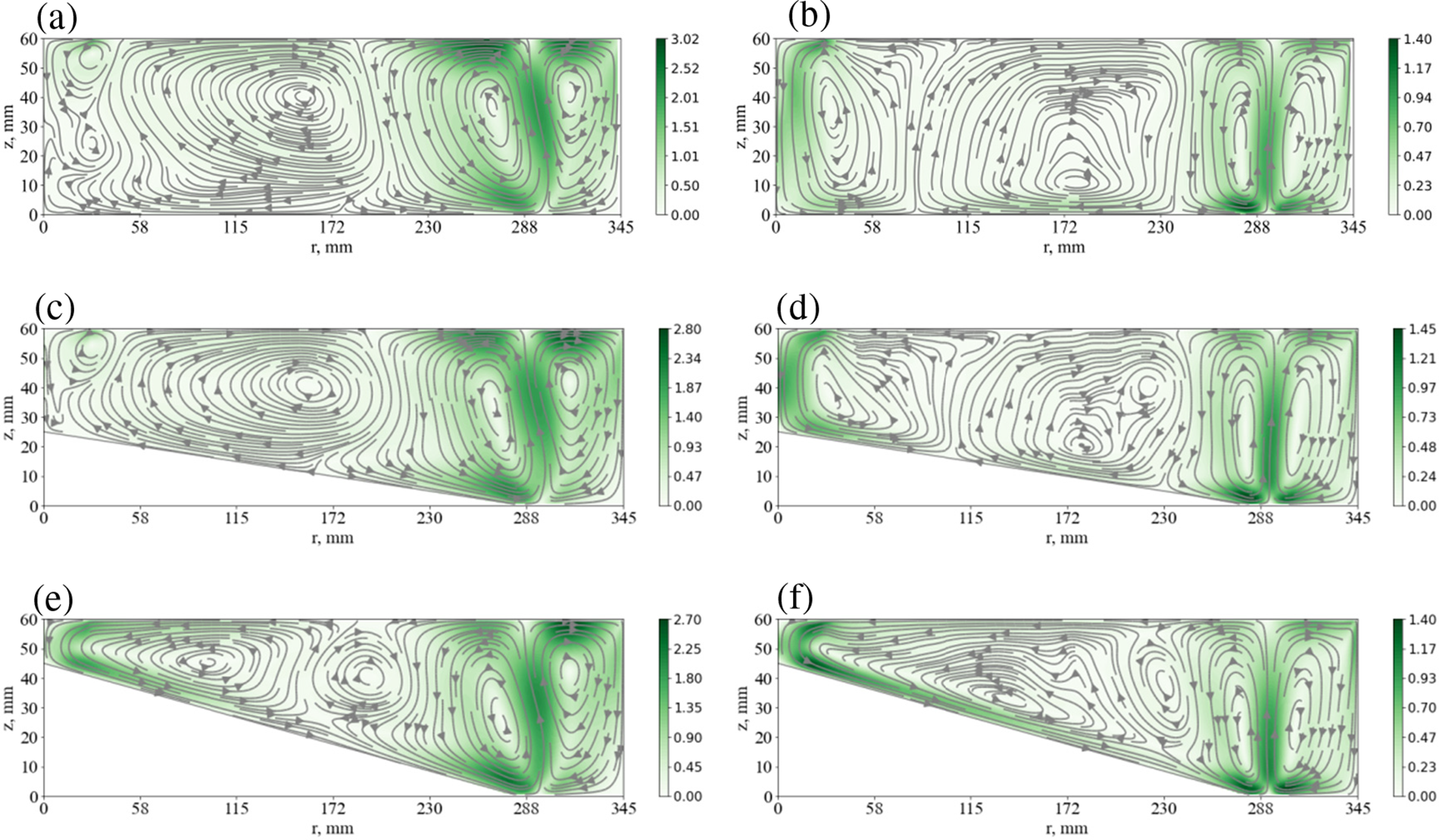
Figure 2: Streamlines of the mean (averaged in time and azimuthal coordinate) meridional circulation, for the aspect ratio a ≈ 0.17 and for different bottom inclination angles (0°, 5°, 10°), in the case of slow rotation (Ω = 0.11, rad/s)–left column, and fast rotation (Ω = 0.37, rad/s)–right column. The magnitude of velocity is shown by color bar in mm/s
The obtained results showed that relatively small bottom tilt (5°) does not lead to qualitative changes in the meridional circulation structure both in the case of slow and fast rotations (Figs. 2a–2d), but a significant change in the layer thickness (especially near the rotation axis), affects the quantitative characteristics of the flow. The further increase in inclination results in noticeable changes in the mean flow structure (Figs. 2e–2f). Specifically, in case of slow rotation most of the cold fluid descends near the axis of rotation and the intensive polar cell is formed. Small cell, which is adjacent to polar cell, at this regime is produced by waves (we show it below).
In case of fast rotation the analog of Ferrel cell becomes smaller and analog of polar cell substantially larger. This remarkable transformation of the polar cells is a result of the downhill cold flows due to noticeable tilt. Another important question concerns the structure of mean zonal flows. The zonal flows are produced by the transport of angular momentum by radial flows and baroclinic waves. In all considered regimes the zonal cyclonic circulation dominates except sidewall region (see Fig. 3) despite the different structure of the meridional circulation. Such distribution of zonal flows is necessary to achieve angular momentum balance. This problem was previously described in [25,26]. The injection of angular momentum into the layer occurs near the sidewall, where an intense anticyclonic motion is formed. Since the upper boundary is free, the angular momentum sink (a cyclonic flow near the solid boundary) necessary to balance angular momentum fluxes should be located in the bottom area. Therefore, during non-stationary stage the cyclonic flow grows until it achieves the bottom. The meridional circulation in the quasi-stationary state only redistributes the cyclonic angular momentum but cannot change the sign of the azimuthal motion. The noticeable change in the structure of zonal flows appears at a strong tilt (10°) due to the transformation of meridional circulation (Figs. 3e and 3f). The downhill flows near the bottom result in the anticyclonic flows in the lower layer. Also, we note that the magnitude of zonal flows decreases with tilt for both slow and fast rotation. To illustrate the location and intensity of wave motion, the energy distribution of radial velocity fluctuations is given (see Fig. 4). The waves for all regimes are located in the upper layer because of damping in the Ekman layer near the bottom. For slow rotation without tilt the waves are located only near the axis of rotation.
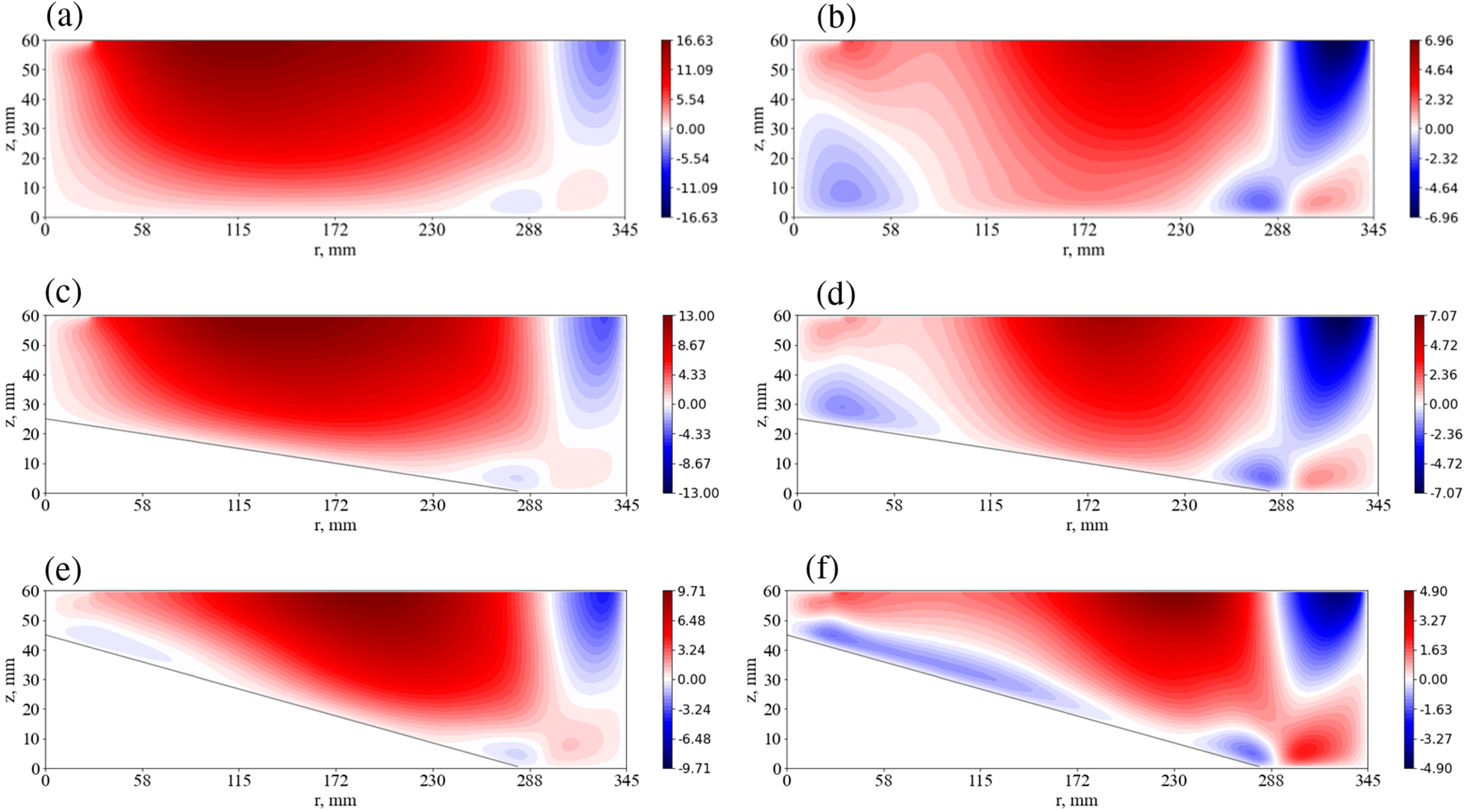
Figure 3: Mean azimuthal velocity fields (averaged in time and azimuthal coordinate), for the aspect ratio a ≈ 0.17 and for different bottom inclination angles (0°, 5°, 10°), in the case of slow rotation (Ω = 0.11, rad/s)–left column, and fast rotation (Ω = 0.37, rad/s)–right column. The magnitude of velocity is shown by the color bar in mm/s
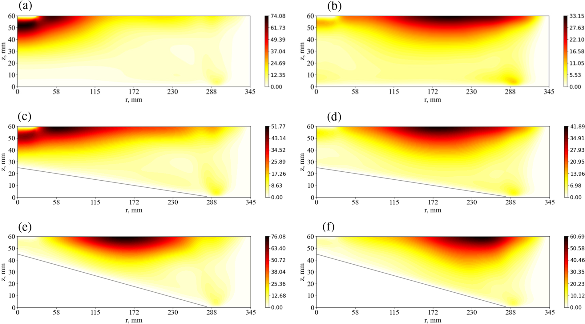
Figure 4: Energy of radial velocity fluctuations, for the aspect ratio a ≈ 0.17 and for different bottom inclination angles (0°, 5°, 10°), in the case of slow rotation (Ω = 0.11, rad/s)–left column, and fast rotation (Ω = 0.37, rad/s)–right column. The magnitude is shown by the color bar in mm2/s2
The tilt of the bottom causes the wave region to shift to larger radii. In case of a strong tilt the waves are located at the middle radii. Tilting at the fast rotation results in the narrowing of the wave region, they become more localized in the middle radii. The waves in considered regimes are a superposition of different modes [21]. In Fig. 5, we present the distribution of wave mode energy for different bottom tilt. The radial velocity component is decomposed into a Fourier series in the azimuthal direction:
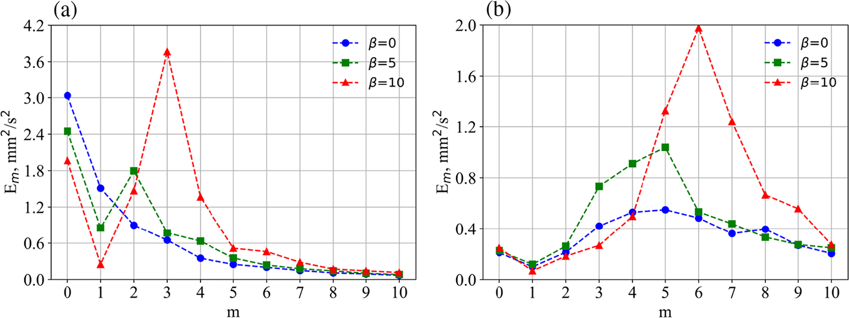
Figure 5: Energy of different azimuthal modes for different bottom inclinations: (a)–slow rotation (Ω = 0.11, rad/s), (b)–fast rotation (Ω = 0.37, rad/s)
where
The energy of each azimuthal mode can be evaluated by
As we see the appearance of tilt leads to wave excitation (mode m = 2) in the case of slow rotation (Fig. 5a). For the stronger tilt waves motion intensifies and mode m = 3 is dominant. At a fast rotation simulating the atmospheric circulation regime, a significant intensification of waves occurs with increasing inclination (Fig. 5b). It should be noted that in the present study, we do not separate the waves of different nature (baroclinic waves and Rossby waves).
The mean and pulsating parts of the flow provide heat transfer and determine the mean temperature distribution (see Fig. 6). We see that tilt results in decreasing temperature gradients and the temperature fields become more homogeneous. This effect can be provided by the appearance of downhill flow and enhanced convective circulation (convective mixing) or by the intensification of the wave motions that also lead to an increase in the mixing of the fluid.
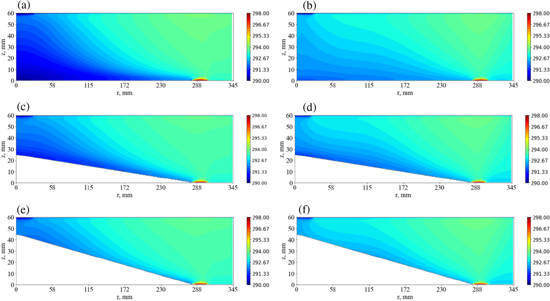
Figure 6: Mean temperature fields (averaged in time and azimuthal coordinate), for the aspect ratio a ≈ 0.17 and for different bottom inclination angles (0°, 5°, 10°), in the case of slow rotation (Ω = 0.11, rad/s)–left column, and fast rotation (Ω = 0.37, rad/s)–right column
The main purpose of the presented study is to investigate the influence of aspect ratio and bottom tilt on the flow structure in a rotating layer with horizontal temperature difference. Two cases are considered: the slow rotation regime, which is stable to baroclinic wave formation, and the fast rotation regime, or “atmospheric” regime, which has a flow structure similar to the general atmosphere circulation, including developed baroclinic waves. The mean flow without tilt is similar to the described in [21], so the increase of the aspect ratio from a ≈ 0.09 to a ≈ 0.17 does not lead to crucial changes in the flow structure. The relatively small tilt (5°) leads to quantitative changes in the flow that preserve the flow structure. Further increase of tilt to 10° results in crucial changes both in the flow structure and intensity of the wave motions. The strong impact on the flow structure has the formation of downhill cold flow due to bottom tilt. We assume that the main factor that leads to the intensification of wave motions is the beta effect and the generation of Rossby waves. The interaction of baroclinic waves and Rossby waves is not considered here but it is a very interesting problem that we will address in a further study. Another interesting issue for our future studies is an interaction between large-scale baroclinic waves small scale inertia-gravity waves with possible resonance effects [15,27–30]. The transformation of the meridional circulation at large tilt results in noticeable changes in zonal flows, in particular, to the formation of an anticyclonic circulation near the bottom. The general changes in the flow structure and dynamics lead to remarkable changes in the mean temperature fields. A large inclination results in a substantial decrease of temperature gradients and homogenization of temperature fields.
Acknowledgement: The computing time for simulation in Triton supercomputer of the ICMM UB RAS is provided by RAS Project AAAA-A19-119012290101-5. We sincerely thank anonymous reviewers for their constructive comments which led to serious improvement of the manuscript.
Funding Statement: This research was supported by Russian Science Foundation Grant RSF-22-21-00572 (https://rscf.ru/project/22-21-00572/).
Author Contributions: The authors confirm their contribution to the paper as follows: study conception and design: A. Sukhanovskii; data collection: A. Vasiliev; analysis and interpretation of results: A. Sukhanovskii, A. Vasiliev, E. Popova; draft manuscript preparation: A. Sukhanovskii, A. Vasiliev. All authors reviewed the results and approved the final version of the manuscript.
Availability of Data and Materials: The data acquired during this study are available from the corresponding author upon reasonable request.
Conflicts of Interest: The authors declare that they have no conflicts of interest to report regarding the present study.
References
1. Lappa, M. (2012). Rotating thermal flows in natural and industrial processes, 1st edition, pp. 1–540. Chichester, England: John Wiley & Sons, Ltd. [Google Scholar]
2. Read, P. L., Pérez, E. P., Moroz, I. M., Young, R. M. B. (2014). General circulation of planetary atmospheres: Insights from rotating annulus and related experiments. In: Modeling atmospheric and oceanic flows: insights from laboratory experiments and numerical simulations, pp. 368. USA, Washington DC: American Geophysical Union. [Google Scholar]
3. Lonner, T. L., Aggarwal, A., Aurnou, J. M. (2022). Planetary core-style rotating convective flows in paraboloidal laboratory experiments. Journal of Geophysical Research: Planets, 127(10), e2022JE007356. [Google Scholar]
4. Lemasquerier, D., Favier, B., Le Bars, M. (2021). Zonal jets at the laboratory scale: Hysteresis and Rossby waves resonance. Journal of Fluid Mechanics, 910, A18. [Google Scholar]
5. Lemasquerier, D., Favier, B., Le Bars, M. (2023). Zonal jets experiments in the gas giants’ zonostrophic regime. Icarus, 390, 115292. [Google Scholar]
6. Stewart, K. D., Macleod, F. (2022). A laboratory model for a meandering zonal jet. Journal of Advances in Modeling Earth Systems, 14(7), e2021MS002943. [Google Scholar]
7. Kishida, Y., Tanaka, M., Esaka, H. (1993). Appearance of a baroclinic wave in Czochralski silicon melt. Journal of Crystal Growth, 130, 75–84. [Google Scholar]
8. Kishida, Y., Okazawa, K. (1999). Geostrophic turbulence in CZ silicon crucible. Journal of Crystal Growth, 198–199, 135–140. [Google Scholar]
9. Azoui, H., Bahloul, D., Soltani, N. (2018). Three-dimensional numerical investigation of convective thermal instabilities in the sapphire melt for czochralski growth process. Fluid Dynamics & Materials Processing, 14(2), 87–105. https://doi.org/10.3970/fdmp.2018.01149 [Google Scholar] [CrossRef]
10. Soltani, N., Rahal, S. (2017). Control of the convective flow instabilities in a simulated Czochralski growth system. Fluid Dynamics & Materials Processing, 13(1), 1–17. https://doi.org/10.3970/fdmp.2017.013.001 [Google Scholar] [CrossRef]
11. Liu, Y., Zhang, L., Liu, H., Yin, L., Xiao, Y. et al. (2022). Influence of aspect ratio on instability of the mixed convection in Czochralski model. Journal of Crystal Growth, 589, 126670. [Google Scholar]
12. Hide, R. (1953). Some experiments on thermal convection in a rotating liquid. Quarterly Journal of the Royal Meteorological Society, 79, 161–161. [Google Scholar]
13. Marshall, S., Read, P. (2018). An experimental investigation of blocking by partial barriers in a rotating baroclinic annulus. Geophysical & Astrophysical Fluid Dynamics, 112, 97–129. [Google Scholar]
14. Marshall, S., Read, P. (2020). Thermal versus mechanical topography: An experimental investigation in a rotating baroclinic annulus. Geophysical & Astrophysical Fluid Dynamics, 114, 763–797. [Google Scholar]
15. Rodda, C., Borcia, I. D., Le Gal, P., Vincze, M., Harlander, U. (2018). Baroclinic, Kelvin and inertia-gravity waves in the barostrat instability experiment. Geophysical & Astrophysical Fluid Dynamics, 112, 175–206. [Google Scholar]
16. Vincze, M., Borcia, I. D., Harlander, U. (2017). Temperature fluctuations in a changing climate: An ensemble-based experimental approach. Scientific Reports, 7, 1–9. [Google Scholar]
17. Rodda, C., Harlander, U., Vincze, M. (2022). Jet stream variability in a polar warming scenario—A laboratory perspective. Weather and Climate Dynamics, 3, 937–950. [Google Scholar]
18. Harlander, U., Borcia, I. D., Vincze, M., Rodda, C. (2022). Probability distribution of extreme events in a baroclinic wave laboratory experiment. Fluids, 7(8), 274. [Google Scholar]
19. Vincze, M., Hancock, C., Harlander, U., Rodda, C., Speer, K. (2023). Extreme temperature fluctuations in laboratory models of the mid-latitude atmospheric circulation. Scientific Reports, 13(1), 20904. [Google Scholar] [PubMed]
20. Scolan, H., Read, P. L. (2017). A rotating annulus driven by localized convective forcing: A new atmosphere-like experiment. Experiments in Fluids, 58, 75. [Google Scholar]
21. Sukhanovskii, A., Popova, E., Vasiliev, A. (2023). A shallow layer laboratory model of large-scale atmospheric circulation. Geophysical & Astrophysical Fluid Dynamics, 117(3), 155–176. [Google Scholar]
22. Harlander, U., Sukhanovskii, A., Abide, S., Borcia, I. D., Popova, E. et al. (2023). New laboratory experiments to study the large-scale circulation and climate dynamics. Atmosphere, 14, 836. [Google Scholar]
23. Vasiliev, A., Popova, E., Sukhanovskii, A. (2023). The flow structure in a laboratory model of general atmosphere circulation. Computational Continuum Mechanics, 16(3), 321–331. [Google Scholar]
24. Sukhanovskii, A., Evgrafova, A., Popova, E. (2016). Horizontal rolls over localized heat source in a cylindrical layer. Physica D: Nonlinear Phenomena, 316, 23–33. [Google Scholar]
25. Batalov, V., Sukhanovsky, A., Frick, P. (2010). Laboratory study of differential rotation in a convective rotating layer. Geophysical & Astrophysical Fluid Dynamics, 104(4), 349–368. [Google Scholar]
26. Evgrafova, A., Sukhanovskii, A. (2022). Angular momentum transfer in direct numerical simulations of a laboratory model of a tropical cyclone. Geophysical & Astrophysical Fluid Dynamics, 116(3), 185–205. [Google Scholar]
27. Iga, K. (1993). Reconsideration of Orlanski’s instability theory of frontal waves. Journal of Fluid Mechanics, 255, 213–236. [Google Scholar]
28. Sakai, S. (1989). Rossby-Kelvin instability: A new type of ageostrophic instability caused by a resonance between Rossby waves and gravity waves. Journal of Fluid Mechanics, 202, 149–176. [Google Scholar]
29. Lovegrove, A. F., Read, P. L., Richards, C. J. (2000). Generation of inertia-gravity waves in a baroclinically unstable fluid. Quarterly Journal of the Royal Meteorological Society, 126, 3233–3254. [Google Scholar]
30. Rodda, C., Hien, S., Achatz, U., Harlander, U. (2020). A new atmospheric-like differentially heated rotating annulus configuration to study gravity wave emission from jets and fronts. Experiments in Fluids, 61, 2. [Google Scholar]
Cite This Article
 Copyright © 2024 The Author(s). Published by Tech Science Press.
This work is licensed under a Creative Commons Attribution 4.0 International License , which permits unrestricted use, distribution, and reproduction in any medium, provided the original work is properly cited.
 Downloads
 Citation Tools