
 Submit a Paper
 Propose a Special lssue
 Open Access
REVIEW

Wind Turbine Composite Blades: A Critical Review of Aeroelastic Modeling and Vibration Control
1 College of Mechanical & Electronic Engineering, Shandong University of Science & Technology, Qingdao, 266590, China
2 School of Mechanical & Automotive Engineering, Liaocheng University, Liaocheng, 252059, China
* Corresponding Author: Dan Xu. Email:
Fluid Dynamics & Materials Processing 2025, 21(1), 1-36. https://doi.org/10.32604/fdmp.2024.058444
Received 12 September 2024; Accepted 05 December 2024; Issue published 24 January 2025
 View Full Text
 Download PDF
Abstract
With the gradual increase in the size and flexibility of composite blades in large wind turbines, problems related to aeroelastic instability and blade vibration are becoming increasingly more important. Given their impact on the lifespan of wind turbines, these subjects have become important topics in turbine blade design. In this article, first aspects related to the aeroelastic (structural and aerodynamic) modeling of large wind turbine blades are summarized. Then, two main methods for blade vibration control are outlined (passive control and active control), including the case of composite blades. Some improvement schemes are proposed accordingly, with a special focus on the industry’s outstanding suppression scheme for stall-induced nonlinear flutter and a new high-frequency micro-vibration control scheme. Finally, future research directions are indicated based on existing research.Graphic Abstract
Keywords
Nomenclature
| B-L | Beddoes Leishman |
| BEM | Blade element momentum |
| CAS | Circumferential antisymmetric stiffness |
| CDC | Critical damping control |
| CFD | Computational fluid dynamics |
| CSM | Cell-set model |
| CUS | Circumferentially uniform stiffness |
| FBF | Finite blade function |
| FBTC | Fused blade tip construction |
| FE | Finite element |
| FP | Flexible piezoelectric |
| FSI | Fluid-solid interaction |
| GA | Genetic algorithm |
| GEB | Geometrically exact beam |
| HBM | Harmonic balance method |
| HFMV | High-frequency micro-vibration |
| LQG | Linear quadratic gaussian |
| METE | Multi-elements trailing edge |
| MR | Magnetorheological |
| NREL | National Renewable Energy Laboratory |
| NS | Navier-Stokes |
| ONERA | A well-known stall-induced aerodynamic model |
| OPC | OLE (Object Linking and Embedding) for process control |
| OPC UA | Open Platform Communications Unified Architecture |
| PDSS | Passive damping of synchronous switch |
| RANS | Reynolds averaged Navistox simulation |
| SMA | Shape memory alloy |
| TEF | Trailing edge flap |
| TLCD | Tuned liquid column damper |
| TMD | Tuned Mass Damper |
| TWB | Thin-walled beam |
| Airfoil Parameters | |
| | Chord length |
| | The drag force |
| | Signal from feedback controller or forward controller |
| | The cyclic term in lift |
| | The non cyclic term in lift |
| | Aerodynamic moment |
| | Element displacement of composite material elastic unit |
| | Wind speed |
| | Inflow wind speed |
| | The lead-lag, flap-wise, and stretching directions |
| | |
| | Attack angle of the blade |
| | External pitch angle |
| | Elastic torsion angle of the blade |
| | Elastic torsion angle of the beam |
| | Inflow angle of the blade |
| | Wind turbine speed |
With the growth of global energy demand, the expanding need for energy supply and related technology have brought enormous pressure to the world. In the meantime, environmental pollution and climate change have drawn widespread attention. Therefore, developing clean and renewable energy has become one of the focuses of government bodies and scientific research groups. Wind energy, among various renewable energy sources, has become a widely accepted clean energy due to its stable source, enormous potential, pollution-free nature, and common availability. Therefore, wind wind-power generation has become an important subject of clean energy development [1]. By 2030, the wind energy installed capacity in Europe is expected to reach approximately 323 gigawatts (GWs) (of which 253 GW is onshore), an increase from 160 GW in 2016 and approximately equivalent to one-third of the EU’s electricity demand. In East and Southeast Asia, the proportion of renewable energy in total energy may increase by more than one-fifth by 2030. It is estimated that by 2030 and 2050, wind power generation will reach 450 and 1200 GWs, respectively [1,2]. Wind-driven blades are an important component of wind turbines, and their aerodynamic and aeroelastic properties (including structure and aerodynamic performance) directly determine the service life and efficiency of wind turbines. With the development of large and efficient wind turbines, the size and flexibility of the blades continue to increase, making them more prone to flutter, thereby endangering the structural safety and aerodynamic performance of the blades. The typical characteristics of turbines with high-rated power are longer and heavier blades. Due to the increase in mass, the influence of gravity and inertia loads on wind turbine blades cannot be ignored compared to aerodynamic loads [3,4]. These high gravity loads cause higher stress in the blade material, increase fatigue, and transfer larger loads to the rotor shaft and turbine tower. Therefore, an increasing number of typical cross-sectional units of large wind turbine blades have adopted (or partially adopted) flexible composite material structures [5]. Therefore, the research on the aeroelasticity and aerodynamics of wind turbine blades is flourishing, which also makes the research and development of aeroelastic system modeling and vibration control technology more important in terms of theoretical significance and engineering value.
The modeling and vibration control technology of aeroelastic systems involve a wide range of aspects. It includes structural modeling, aerodynamic evaluation, coupling behavior and aeroelastic response analysis, flutter response and flutter wind speed analysis, nonlinear vibration and vibration control technology, as well as related structural health detection technology, etc. Common structural modeling methods include the assumed modal method, finite element method and multi-body dynamics method. In the early days, scholars conducted a lot of research in this area. The assumed model method and finite element method are often applied in 1D and 3D beams. Early versions of GH Bladed software [6] integrate mature applications of assumed modal methods. Manolas et al. [7] investigated the second-order beam model based on finite element analysis, which improved the accuracy of the aeroelasticity analyses. However, the finite element analysis here cannot effectively describe large structural displacements and is not suitable for the analysis of high-order terms. Wang et al. [8] proposed a geometrically exact beam theory model that can effectively describe large structural displacements. However, it has several parameters and is computationally intensive. The multi-body dynamics method has positive significance in 3D beam structures, large displacements and deformations, as well as nonlinear analysis. It can improve accuracy but is built on a large number of independent rigid bodies, so the computational cost is high [9]. The common methods for evaluating blade aerodynamics include blade element momentum theory, computational fluid dynamics simulation, and wind tunnel testing experiment. The blade element momentum method [10] divides the blades into blade units with an infinitely thin thickness along the span direction, which is based on the quasi-steady flows and two-dimensional aerodynamics. It cannot accurately simulate the eddy currents generated by the blades and does not consider large blade deformations because it ignores the radial flow component. The computational fluid dynamics simulation can accurately obtain specific and dynamic information about the flow field around small blades, with the advantages of low cost and visualization. However, for large blades and higher precision requirements, significant computational consumption is required [11]. Wind-tunnel experiment requires miniature models that are difficult to match real-time wind conditions, and the physical equipment, including detection instruments, is expensive and requires complex technical operations [12].
Meanwhile, dedicated to seeking solutions to the above problems, this article will provide a detailed overview in the following sections. Meanwhile, coupling behavior (including structural displacements coupling and flow-structure coupling), aeroelastic response analysis, flutter response and flutter wind speed analysis, nonlinear vibration and vibration control technology, as well as related structural health detection technology, are all issues that need further exploration. The bend-twist coupling and adaptive control based on structural displacement were elaborated in detail [13] to achieve the aeroelastic coupling control strategy, which facilitates further analysis of the coupling effect and large deformation response of blades. Nonlinear flutter analysis of a bent-twist coupled composite wind turbine blade was addressed to improve the aeroelastic performance of large blades and predict flutter wind speed based on the coupling of bending and torsional stiffness [14]. The flutter performance based on flutter wind speed is often tested through micro-models and wind tunnel testing [15]. The geometric nonlinear deformation behavior [16] and nonlinear aeroelastic response [17] can be solved for nonlinear vibration response through multi-body dynamics analysis and Hamiltonian principle, respectively. And the fluid-structure interaction response [18], especially for small wind turbines and vertical axis wind turbines, is often solved through computational fluid dynamics analysis. The vibration control of megawatt-level wind turbines [19], including their supporting structural health detection and sensing measurement technology [20,21], is a more complex and important issue, which will be further reviewed in the following chapters of this article.
This article systematically reviews the research progress on modeling and vibration control of composite blades for wind turbines. The wide topics in this field are addressed in this study, including structural modeling, aerodynamic modeling, passive vibration control technology, and active vibration control technology for wind turbine blades. Moreover, this article also presents the insights of various advanced aeroelastic system modeling schemes and innovatively discusses the suppression planning of stall-induced nonlinear flutter, as well as a new high-frequency micro-vibration (HFMV) control scheme.
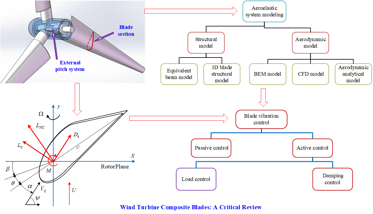
Accurate modeling and analysis of blade aeroelasticity and aerodynamics are key to improving wind turbine design and optimizing operating conditions. The aeroelastic system modeling of wind turbine blades mainly includes two aspects: structural modeling and aerodynamic modeling. Fig. 1 shows the classification and composition of aeroelastic modeling of wind turbine blades.
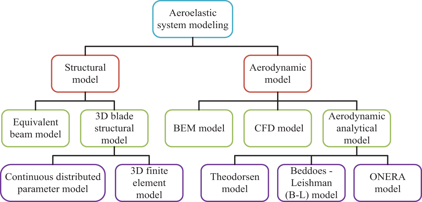
Figure 1: The classification and composition of aeroelastic system modeling of wind turbine blades
Structural modeling is a mechanical description of the internal stress, strain, and deformation states (such as bending, twist/torsion, shear, etc.) of a blade, based on its material, structure, and load. Structural modeling can evaluate the strength, stiffness, and stability of a blade, and provide deformed blade shape lines for subsequent aerodynamic modeling. The current structural modeling mainly includes equivalent beam models and three-dimensional blade structure models.
2.1.1 The Equivalent Beam Model
The large elongated blades of wind turbines are slender structures, with the chord direction of the blades much smaller than the length direction. This structure can be idealized as a beam structure along the length direction. The cross-section changes perpendicular to the axis of the beam (span direction).
(1) Two important equivalent beam models
The Euler-Bernoulli beam model [22] and Timoshenko beam model [23] are the most commonly used beam models for wind turbine blades. Among them, the Euler-Bernoulli beam model, commonly known as the classical beam model, has demonstrated resistance to tensile, torsional, and bending loads without considering shear deformation effects. In contrast, the Timoshenko beam model was proposed by Timoshenko in the early 20th century and includes shear deformation effects. Compared with the Euler-Bernoulli beam model, it is more suitable for describing thick and short beams. For wind turbine blades with slender structures, the calculation results of Timoshenko beam and Euler-Bernoulli beam models are similar. The advantage of Euler Bernoulli beams is their ease of engineering application; therefore, the application of Euler Bernoulli beam models is becoming increasingly widespread [24]. Both of the above are linear beam models. For nonlinear beam models with large disturbances, Hodges [25] provides a geometrically accurate beam theory that considers the geometric nonlinearity caused by large bending deformation and can accurately represent the torsion and displacement of deformed beams. Fig. 2 shows a schematic of beam under transverse follower force
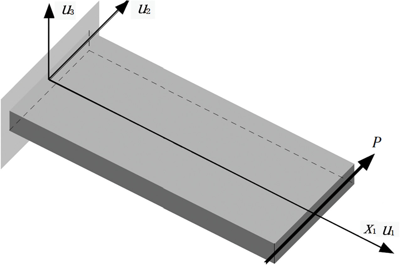
Figure 2: The schematic of beam under transverse follower force in Reference [25]. Copyright ©2003, Dewey H. Hodges
There are also many mathematical modeling methods for equivalent beam models, and the latest achievements include the following cases. A large deflection blade model was developed to study the dynamic response using the updated Lagrangian equation to derive the large deflection blade model from the Euler–Bernoulli beam [26]. The Laplace transformation and Green’s function methods were employed to model a wind turbine blade using the Euler-Bernoulli beam model to obtain fundamental solutions of the governing equations [27]. Based on Timoshenko beam theory, a new modeling approach of the blade was proposed, according to the strain energy release rate and Castingliano theory and considering the stiffness nonlinearity. The modeling approach is validated by the measured natural frequencies of an intact blade [28].
The equivalent beam model has the advantages of fast and simplified calculation and analysis. With appropriate formulation, it can save a lot of time and obtain accurate results. Therefore, most aeroelastic models represent the blade as a series of one-dimensional beam elements that exhibit flap-wise bending and torsional displacements.
(2) Further discussion
The equivalent beam model includes the aforementioned 1D beam model and 3D beam model. Of course, the assumed modal method mentioned earlier, the finite element method and multi body dynamics method are still applicable for modeling. These methods have been applied in recent years; they are still being improved. Zhou et al. [13] utilized the geometrically exact beam theory and implemented analysis of structure and inflow based on the blade’s geometric nonlinearity, with large deformations analyzed using updated Lagrange method. Xu et al. [16] investigated the geometric nonlinearity and aeroelastic problems caused by large deformations based on multi-body dynamics analysis. The results indicate that when the deformation of the blade increases, the multi-body dynamics analysis method can predict the deformation under static load more accurately than other analysis methods, especially when the blade loading exceeds the maximum design load and the tip deflection is greater than the blade span. And its computational efficiency is not lower than finite element analysis, especially in extreme wind conditions, it has positive application value.
The structural theory and microscopic theory of Euler Bernoulli bending beams continue to develop and have been widely applied [29–32]. Fudlailah et al. developed an advanced Euler Bernoulli beam theory based on a Python computer program as a numerical tool, considering the combination of blade geometry and element momentum theory. This theory achieves effective calculation of blade structure response under aerodynamic loads without sacrificing computational accuracy [29]. Khabiri et al. also considered geometric deformation and studied the influence of fractional order Euler Bernoulli beam models. Due to the geometric properties and fractional order effects of beams, changing the fractional order parameters will significantly affect the deflection behavior of bent beams [30]. Krysko et al. optimized the maximum stiffness of the beam microstructure from a microscopic theoretical perspective by performing topological optimization under given boundary and load conditions. They also studied the influence of scale size parameters on chaotic beam dynamics [31]. Malik et al. conducted a study based on composite microscopic theory, treating Chicken Feather Fiber with Epoxy-Resin as a beam structure, and investigated the vibration frequency at high temperatures. Modal analysis was performed on the first eight modes [32]. All these studies provide new ideas for the study of aeroelastic deformation and vibration frequency of blades.
In addition, the universality of the equivalent beam model is also reflected in the use of various thin-walled structures in the cross-section of the beam, with the thickness being h(s). For example, using elliptical thin-walled structures or box beam structures. Fig. 3 shows two examples of thin-walled structures of composite materials. At this point, due to the elasticity of composite materials, torsional displacement is also being considered.
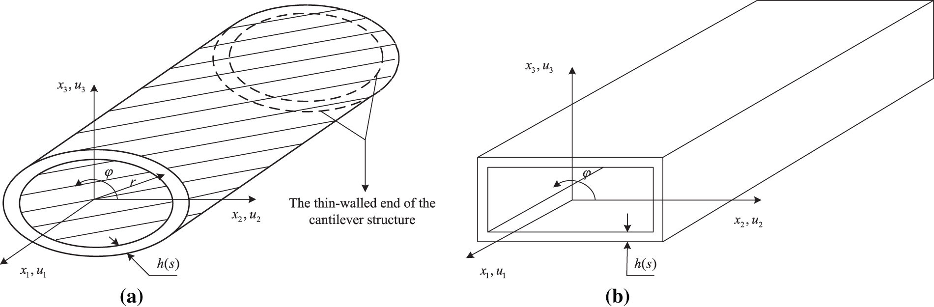
Figure 3: The thin-walled structures of composite materials. (a) Elliptical shape; (b) box shape
2.1.2 3D Blade Structural Model
The structural modeling of the 3D blade is mainly divided into the 3D finite element (FE) modeling and the continuous distributed parameter modeling.
(1) 3D FE modeling approach.
Hamdi et al. [33] comprehensively constructed an approximate structural model of the blade including centripetal force, gravitational force, rotational motion, and aerodynamic force, and studied the modal and dynamical response of each order frequency based on FE analysis. Horcas et al. [34] considered blade pre-torsion scheme and used FE analysis to model the a DTU-10MW blade constructed by lamination of glass fiber reinforced composites. The composite layers of the blade were defined as a stacked sequence of layers, constructed as multidirectional layers (i.e., each layup contains fibers with multiple layup angles). Rezaei et al. [35] modeled the structure of the blade in an Ansys FE model using 100-node, 12-degree-of-freedom beam with 188 cells for the blade. A single-node rigid body MASS21 cell was used to model the rigid nacelle and hub assembly in a simplified manner, and rotating joint constraints were applied between the hub and nacelle components to simulate the rotation of the rotor. Yang et al. [36] imported the National Renewable Energy Laboratory (NREL)-5MW turbine blade model built by SolidWorks software into Hypermesh meshing tool to perform surface blade mesh discretization. The blades used are thin-walled structures, and the FE model adopts Ansys shell elements for modal and frequency analysis. Wang et al. [37] also investigated the NREL-5MW model based on NX Open Grip parametric language to design the composite material layers, used FE software to analyze the bending torsional coupling characteristics, and implemented the frequency analysis using Ansys shell cells.
In the comprehensive application of FSI, the FE modeling methods have also been increasingly widely used. The FE model was used to perform fluid-solid interaction (FSI) using ABAQUS to study damage mechanisms of a large-span composite blade, with the wind velocity model as well as the tower shadow effect considered for fluid elements as boundary condition. Meanwhile, using a local T-shape adhesive structure, effects of some important factors on damage mechanisms of the composite blade were discussed including the wind velocity, the strength, thickness and width of adhesive layer [38,39]. Considering the principle of 3D printing, reference [40] established a model using the FE analysis to discuss the effects of fiber content, fiber aspect ratio, fiber orientation, and local fiber density. This model not only helps to accurately predict issues related to the recycling of wind turbine blades, but also has enlightening significance for the safety framework of the fiber structure of composite blades [40]. A structural model based on the FE analysis was developed for generation of large datasets of high-fidelity aerodynamic loading, displacement and stress for a NREL 5MW wind turbine blade [41]. Based on the datasets, analysis of structural responses of the turbine blade and their possible shifts with respect to a change in the operating conditions, e.g., rotor plane tilting and yawing, were performed.
The disadvantages of the 3D FE blade modeling method are over simplification, limitation of the structural units of the FE software, and difficulty in analyzing the transient responses of composite blades with complex structures. However, improving the skin structure or shape of the blades can expand the application of the FE method, and the improvement of the FE method itself is not absolutely impossible. Tavares et al. and Peeters et al. [42,43] explored the modeling of wind turbine blades under torsional loads using an Outer Mold Layer shell model and FE analysis. Fig. 4 is the flowchart of the process to generate a high-fidelity model of a wind turbine blade, based on the study by Tavares with the original software developed by Peeters. Vaz et al. [44] placed diffusers around wind turbines and provided a “Finite Blade Function (FBF)”. FBFs retain the finite limit of axial velocity, but do not alter the traditional zero limit of circumferential velocity. On this basis, the mechanism of aerodynamics has been thoroughly studied. Dash et al. [45] used a stochastic finite element method to quantify the uncertainty of the dynamic response of carbon fiber reinforced composite blades during brake manipulation. Albanesi et al. [46] used an inverse finite element method to analyze the geometric shape of large elastic deformation blades caused by loads. The blades are made of multi-layer composite materials, based on aerodynamic analysis, and do not require further interaction between the two solvers in FE analysis. Chakravarthy et al. [47] discussed different FE modeling strategies for complex shaped 3D composite structures, and analyzed and compared marine propeller blades and metal blades, providing ideas for FE analysis of various shapes of wind turbine blades.
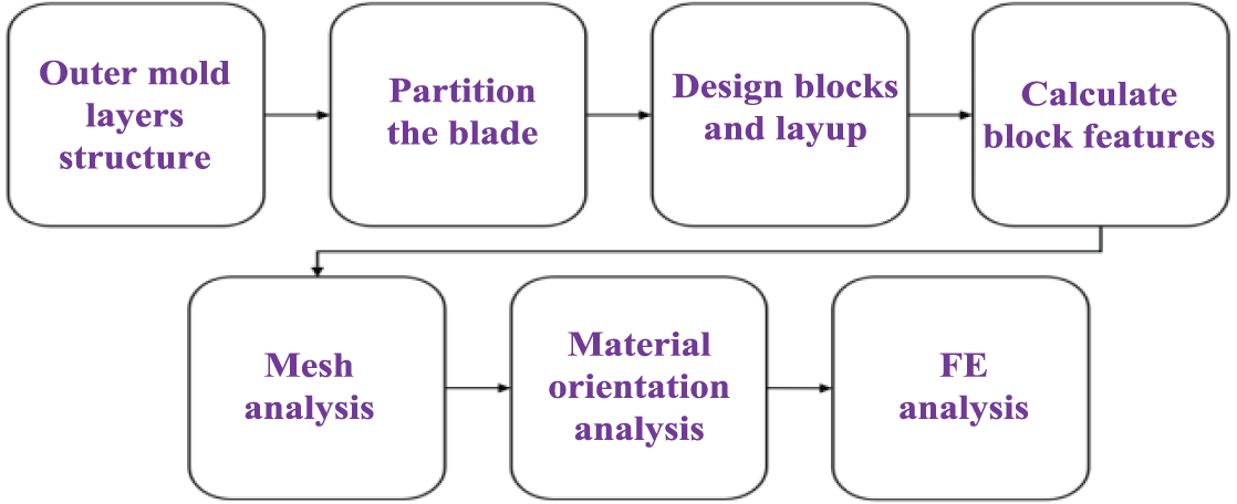
Figure 4: The flowchart of the process to generate a high-fidelity model of a wind turbine blade
(2) The continuous distributed parameter model
The continuous distributed parameter model was established based on the vibration superposition method or the hypothetical modal method to derive the relative relationship between strain and displacement, stress-strain relationship, and inertia and aerodynamic load equations, and finally established the (partial) differential equations of motions of elastic blade body [22–25]. For example, Gebhardt et al. [48] developed a structural model of a large wind turbine blade based on rigid body dynamics and assumed modal methods, and analyzed the motion equations of a three-blade system. Farsadi et al. [49] derived the displacement and strain fields based on the composite thin-walled beam (TWB) structure, obtained the intrinsic and equilibrium equations and derived the kinetic and potential energies based on the energy method analysis. The geometric nonlinear structural modeling of the TWB structure with a circumferential antisymmetric stiffness (CAS) was studied using Hamilton’s principle, perfectly demonstrating the continuous distributed parametric modeling method of the blade. Wang et al. [50] also derived displacement fields based on composite TWB structures and investigated a coupled flap-wise/twisting structural model including primary and secondary warping as well as transverse shear effects. In fact, Chandra et al. [51] have already investigated the TWB structure modeling of composite bending-twist coupling based on a CAS structure and its derivation used a solid-section approach and contained transverse shear-related couplings with appropriate sectional warping. The discretized solution of the partial differential equations was realized based on Galerkin method.
The continuous distributed parametric modeling method based on composite material structures can fully consider more structural factors and aerodynamic load influencing factors, and is currently the preferred blade structure modeling method. Its disadvantage is that it requires consideration of complex material microscopic theory and mechanical behavior, and the solution method is complex, requiring complex computer simulation technology support. Just in terms of composite microscopic theory, the method or solution for determining mechanical behavior or cross-sectional stiffness is a complex problem. The non-zero beam stiffness matrix terms are defined for use in cross-ply, anti-symmetric layup composite box-beam. These stiffness parameters contain a number of constants. These constants arise from the refined treatment of the two-dimensional in-plane elastic behavior. Please refer to reference [51] for specific calculation schemes and processes.
Further discussion on the continuous distribution parameter model is necessary because composite materials with different layers and structures have different microscopic theories. Given the superior performance of composite materials, another layering method with symmetric layup configuration of circumferentially uniform stiffness (CUS) can also be used in modeling of composite blades. The CUS configuration would exhibit displacements of vertical/lateral bending coupling. Theoretical modeling of CUS-based structure can be implemented based on Hamilton variational principle of elasticity theory. The discretization of aeroelastic equations can also be solved by the Galerkin method. Fig. 5 shows the CUS-based blade system its motion characteristics: (a) the CUS-based deformed blade; (b) the displacements and aerodynamic distribution of CUS-based blade section. The blade section is a single-celled composite structure with CUS configuration. In Fig. 5a, the position of the undeformed blade is in a horizontal position, and its end is represented by the coordinates
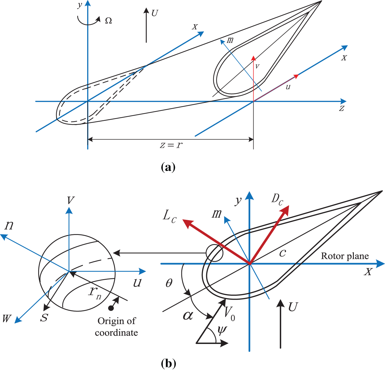
Figure 5: The CUS-based composite blade section and its motion characteristics. (a) CUS-based deformed blade; (b) Displacements and aerodynamic distribution of CUS-based composite blade section
Aerodynamic modeling is the first step in describing aeroelasticity and aerodynamics. The aerodynamic modeling refers to the use of fluid dynamics methods to describe the aerodynamic loads and characteristics of blades, such as lift, drag, moment, etc., based on the interaction between the blades and the flow field. Aerodynamic modeling can calculate the power coefficient, efficiency coefficient, and optimal operating point of wind turbines, and provide a basis for subsequent control strategies. At present, the main methods for aerodynamic modeling include blade element momentum (BEM) theory, computational fluid dynamics (CFD) simulation methods, and aerodynamic analytical methods.
Based on the two-dimensional blade element theory, the BEM theory initially proposed by Glauert [52] assumes that wind turbines are composed of an infinite number of blades, ignoring the mutual influence of adjacent elements, and assuming uniform induced velocity. It simultaneously ignores the effects of hub loss, blade tip loss, and other factors to solve the problem of overall flow field effects and impeller torque changes in the overall flow field of wind turbines. The momentum method and blade element method are used to study the load and flow field changes caused by specific parts of the blade and the surrounding airflow. However, the actual number of wind turbine blades is limited, and the introduction of Prandtl’s tip loss correction makes the theory of lobe momentum closer to the actual situation. Shen et al. [53] analyzed a correction method based on the Prandtl tip loss function when the axial induction coefficient is greater than 0.4. When the wind turbine blades enter a turbulent wake state, the boundary element model fails. The boundary element theory predicts that due to the instability of the free shear layer at the edge of the turbulent wake, the wake velocity becomes negative. Wood et al. [54] developed three methods for directly calculating blade tip loss. The optimal method was determined by comparing these methods with the blade tip losses of an ideal three bladed rotor that were independently and accurately determined at blade tip speed ratios between 0 and 15. Koh et al. [55] compared the performance of various blade tip loss models (including Prandtl correction) using the boundary element method with experimental data from a scaled turbine. Prandtl’s tip loss correction predicted higher power and thrust coefficients. For rigid wings, Spall et al. [56] obtained numerical solutions based on the Prandtl lift line theory and compared the results with those obtained using the established vortex lattice method and the CFD solution of the Euler equation This method is applicable to multiple lift surfaces with arbitrary sweeping. Other researchers have proposed various other corrections to the BEM model based on this, which include: (1) a skewed wake correction [57] that accounts for non-axisymmetric flows (e.g., a wind turbine operating at a yaw angle relative to the incident wind); (2) a stall delay correction [58–60] that accounts for stall delays due to blade rotation; (3) a radial flow correction [61] that considers radial flow in the calculation of aerodynamic loads. These corrections further improve the accuracy of the model. In addition, the validity of BEM models has been widely confirmed by comparison with methods of coupling with CFD based on artificial intelligence algorithm optimization and experimental data processing [62–65]. The BEM modeling has become a standard method for analyzing the aerodynamic performance of wind turbine blades because it is simple, efficient, and well-validated.
Excellent research results have also emerged in the promotion and secondary development of BEM theory. Yirtici et al. [66] investigated the effect of “ice accumulation” in blade leaves using the BEM method with a prediction method based on the extended Messenger model, in a parallel computing environment. Boulamatsis et al. [67] carried out a study using a modified BEM momentum model, considering a rotor blade with variable tip trajectory for a NREL-5MW wind turbine, and modified the model results according to the lift curve theory. Wang et al. [68] combined BEM theory and Geometrically Exact Beam (GEB) theory to improve the accuracy of aeroelastic analysis results for large deformation and large span blades.
The BEM theory can also be used for modeling ultra large flexible blades, as well as for modeling small and micro wind turbine blades. For instance, A nonlinear model was applied to the DTU 10 MW wind turbine mentioned above in reference [26]. The nonlinear aeroelastic dynamics equations of the blade were established using the BEM theory, and time-domain simulations were performed using the nonlinear Newmark and Newton–Raphson methods. An Artificial Bee Colony optimization method based on the BEM Theory was investigated and applied to design a small-scale wind turbine blade [69], with the aerodynamic performance of the optimized blades validated by both experimental and numerical methods. The aerodynamic geometry of the small-scale blade was optimized in terms of optimal chord length and twist angle distributions. The objective function was the power coefficient, and the optimized parameters were the tip speed ratio, wind speed, and the rotor diameter. The important inputs for modeling the platform, hub, and motion are the forces, torques, and energy dissipation provided by the turbine rotor. The BEM can provide a numerically effective method for calculating these quantities in steady flow, making it applicable not only to wind turbine platforms but also to blade platforms under hydraulic and ocean current impacts [70].
Over the years, although the BEM method has undergone many improvements or been combined with other methods, the errors in its calculation results still appear significant as the optimization design of large and elongated blades deepens.
In recent years, with the rapid development of computers, CFD method has received wide attention and more and more applications. CFD provides the flow motion around the blade by solving the continuity and momentum Navier-Stokes (NS) equations. This is a numerical method for virtually obtaining the flow field around a wind turbine, providing detailed information about the airflow and forces on the wind turbine. It is exactly a tool for predicting the aerodynamic performance of wind turbine blades and visualizing the flow field around the blades [71]. CFD is also considered a valuable method for accurately optimizing turbine performance due to its high fidelity [72]. Due to the complex aerodynamic characteristics of wind turbine blades, CFD modeling of wind turbines is very challenging. Currently, a large amount of research is devoted to using CFD to optimize the performance of wind turbines [73]. Usually, there are two main methods in CFD to simulate the rotation of a wind turbine blade, namely the dynamic grid/mesh [74] method and the reference frame method [75]. The dynamic grid method can accurately capture the changes in turbine blade motion caused by changes in air conditions, and is considered more accurate for modeling transient blade motion. The cost of dynamic grids is enormous in terms of computational cost and computer resources, as computational grids need to be regenerated at every time step [76,77]. In the reference frame scheme, the turbine blades and pre-generated meshes across the flow field do not move and the airflow is transferred to the turbine reference coordinates [78,79]. Due to its relatively simple numerical treatment and low computational requirements, the reference frame approach has been widely used for CFD modeling of turbines [80,81]. However, this method can only be applied to static analysis and cannot accurately model the transient motion of the blade [82].
Another important aspect of CFD optimization of wind turbine airfoils is the use of appropriate optimization algorithms to seek and design the optimal shape of the blades. Bedon et al. [83] proposed an optimization model for turbine airfoil shapes by combining a genetic optimizer, a 2D CFD model based on unsteady Reynolds averaged Navistox simulation (RANS), an adaptation calculator, and an airfoil generator. Ribeiro et al. [84] proposed a turbine airfoil optimization technique that couples CFD and optimization algorithms. In this study, the Spalart-Allmaras turbulence model and incompressible RANS equation were used for CFD simulation in steady state. The CFD model was combined with single objective and multi-objective Genetic Algorithm (GA) to optimize the aerodynamic shape of the airfoil. The results showed that the airfoil obtained by single objective and multi-objective GA had similar shapes and aerodynamic coefficients. Sayed et al. [85] used precise CFD loose coupling method to study the aeroelastic response of the blades of a universal DTU-10MW horizontal axis wind turbine, and employed FSI coupling method for aeroelastic simulation. At the same time, the “block structured CFD” solver FLOWER was used to obtain the aerodynamic blade load based on the NS equation in the time domain approximation, and the aerodynamic pressure distribution of the blade was studied in detail. Barr et al. [86] used a CFD solver CRUNCHC and the commercial FE analysis software ABAQUS to calculate static aerodynamic loads and the blade structural deformation, and studied the dynamic process until aeroelastic convergence. In order to make progress in this direction, Li et al. [87] proposed a fast CFD aeroelastic tool, which is built around a simplified reduced order model of aerodynamics. The model is modified for structural feasibility using structural dynamics reanalysis methods.
Under the condition of not emphasizing precision requirements in particular, the CFD method can be used not only for large wind turbines, but also for small-scale wind turbines and other structural forms of wind turbines. A CFD method and a Bayesian analysis were developed to generate a large dataset of high-fidelity aerodynamic loads on the NREL-5MW wind turbine blade, as mentioned in reference [41]. Training Bayesian network models to generate abnormal structural responses or the range and likelihood of blade damage based on input operating conditions provided a reasonable basis for modeling and analysis of aerodynamics. Reference [88] conducted a comprehensive CFD study on the influence of airfoil type and blade size on aerodynamic performance of small wind turbines, and solved the complete 3D NS equation. Four combinations of airfoils and three rotor diameter sizes were studied, and the optimal performance combination was ultimately selected from the research. The performance of a vertical axis turbine mainly depends on the overlap ratio, aspect ratio, number of blades, and blade design. Various researchers have been focusing on using CFD to study and modify these parameters in order to improve the efficiency of turbines. Reference [89] discussed various turbulence models used in different CFD studies of Savonius turbines, and introduced various computational methods used in CFD simulations of Savonius wind and hydraulic turbines, as well as key findings and future development directions of such studies. The traditional blade rotating wind power generation system has many drawbacks, such as natural landscape destruction, flow induced noise, and flickering shadows. Reference [90] proposed a lift generating disc blade power generation mechanism that can effectively generate wind even with a simple structure. The lift data related to the design blade shape was obtained through CFD simulation, and the Modelica language was used to model the multi-physics wind power generation system.
The engineering application of CFD methods is also a topic worthy of attention. One of the issues is low-cost calculation under certain accuracy conditions. Khedr et al. [91] conducted in-depth research on the cross-sectional shape and size of the computational domain, the accuracy of discretization schemes, grid partitioning standards, free flow turbulence intensity, and turbulence modeling, providing reference for standardized simulation settings of small horizontal axis wind turbines. Hamlaoui et al. [92] introduced advanced design techniques based on multi-software analysis, using a reverse CFD actuator disk to determine the radial local chord length distribution on the rotor blades, improving aerodynamic performance and enhancing the potential for optimizing wind farm layout. Ibrahim et al. [93] used ANSYS FENSAP ICE software for numerical CFD icing simulation, and analyzed small-scale blade cross-sections tested in laboratory environments, providing new insights into modeling of glaze ice accretion on large wind turbine blades. The aerodynamic performance cycle of wind turbine blades is also an important issue in engineering. Cheng et al. [94] developed a specific mathematical cyclic integration method and applied it to blades of different relative heights, providing useful reference data for the optimization and reverse design of wind turbine blades. Frulla et al. [95] utilized the optimization software OPTIWR to provide details on construction techniques for transforming optimized configurations into effective working prototypes, and critically discussed suitable production methods for composite blades. In the FE analysis mentioned earlier, blade modeling based on FBFs for skin structures was discussed. In fact, the aerodynamic performance of such skin structures and protective covers can also be analyzed through CFD. Silva et al. [96] conducted a comprehensive analysis of the tip vortex trajectory in a shrouded wind turbine using Reynolds averaged NS numerical solutions, and also discussed the influence of flow conditions on tip vortex trajectory, flow separation, and shroud interaction. This has positive implications for the engineering application of small wind turbines.
The CFD method can effectively calculate the flow field changes through the impeller and the aerodynamic forces acting on the blades. Theoretically, it can effectively solve the aeroelastic stability problem of wind turbine blades. However, if the analysis is not simplified and reduced, the complexity of the NS equation will greatly increase in the process of transforming from the physical domain to the computational domain. Currently, it is difficult to obtain accurate solutions for large wind turbine blades using current technology.
In addition, as mentioned earlier, wind-tunnel testing can serve as a verification tool in CFD analysis. If the aerodynamic conditions can be accurately matched without considering price and cost, wind tunnel testing has positive significance. Wind-tunnel testing aims to further understand the aeroelastic response of flexible blades to reduce storm damage to wind turbines under extreme wind conditions. Reference [12] designed and processed an aeroelastic model of a NREL-5MW wind turbine blade, and investigated the effects of different pitch angles, wind speeds, and wingspan positions on the aeroelastic response characteristics of wind turbine blades through wind-tunnel experiments. Fig. 6 illustrates the frequency spectrum variation pattern of flap-wise acceleration of blade tip at the different pitch angles from wind-tunnel testing based on the NREL-5MW blade analysis.
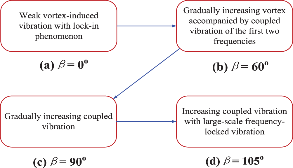
Figure 6: The frequency spectrum variation pattern of flap-wise acceleration of blade tip at the different pitch angles from wind-tunnel testing
2.2.3 Aerodynamic Analytical Model
In recent years, many scholars have transplanted several aerodynamic models from wing profile analysis for the study of flutter in large wind turbine blades, such as the Theodorsen model used for the classical flutter instability of 2D wing vibration, the stall-induced nonlinear aerodynamic models, as well as the unsteady vortex model for studying wake effects. The stall-induced nonlinear aerodynamic models include Beddoes Leishman (B-L) model used for small angle of attack states, and the ONERA model used for high angle of attack analysis.
Stäblein et al. [97] studied the effect of flap bending-torsional coupling on the aeroelastic modal properties and stability limits of attached flow of 2D blade sections based on the Theodorsen model. Boutet et al. [98] used an improved B-L model to predict the aerodynamic load response of airfoils under low Reynolds and low Mach conditions. The steady and unsteady force and pitching moment measurements of airfoils with distinct stall-induced mechanisms were used to demonstrate the validity of the improved B-L model. Tohid et al. [99] cited and demonstrated an aeroelastic tool, hGAST, for consistent prediction of the deflection of material bending-torsional coupled blade beams. In hGAST, a detailed BEM model was used to account for dynamic entry, yaw misalignment, and stall-induced effects through the ONERA model. Gao et al. [100] investigated the key parameters affecting the classical flutter speed of wind turbine blades using a NREL-5MW wind turbine, and established an aeroelastic model to describe blade flutter. This model was composed of a coupled blade aerodynamic model and a structural dynamic model, where the aerodynamic part was the Theodorsen unsteady aerodynamic model, and the structural part was obtained based on the Lagrange equation. Wind turbine blades in wind farms often suffer damage in extreme turbulence intensities (TIs). In order to further analyze this issue through experiments, Wang et al. [101] processed and manufactured a continuous aeroelastic scaling blade, and conducted a multi-parameter study on the aeroelastic response of the blade under different TIs by adjusting the wind fields with grids. The influence of TIs on the wind-induced vibration characteristics of flexible blades under wind turbine shutdown conditions was experimentally studied. The impact of different turbulence on the frequency domain characteristics of blades was analyzed, and the interaction mechanism between blades and turbulent flow fields was deeply explored. The experimental results show that the root-mean-square acceleration of scaled blades is positively correlated with TIs, while the vortex-induced vibration in the direction of the scaled blade flaps is negatively correlated with TIs. In addition, the TIs reduce the frequency locking vibration caused by excitation vibration during the feathering process and lowers the amplitude of blade vortex-induced vibration. This experimental study provides a reference for designing large wind turbines with long flexible blades in coastal, nearshore, and mountainous areas. Therefore, accurately calibrating the aerodynamic forces under different operating conditions and studying the fluid-structure interaction response have positive significance. Liu et al. [102] calibrated a simplified ONERA model, which was first applied in China to study stall-induced nonlinear flutter of wind turbines. As for the wake model, Rodriguez et al. [103] proposed an integrated method that integrates the free vortex wake method into a rotor system suitable for simulating floating offshore wind turbines, generating aeroelastic behavior of rotor wake interaction during operation. Meanwhile, a series of validation studies were conducted on the aerodynamic and structural performance of the rotor of the NREL-5MW wind turbine, and focused on the modeling and simulating different aeroelastic operational conditions of floating offshore wind turbines [104].
Analytical models also include some models generated by certain aeroelastic analysis tools, as well as some semi-analytical models. Ma et al. [105] used an aeroelastic analysis tool called ALFBM to study the coupled aeroelastic wake behavior of a single NREL-5MW wind turbine at different inflow velocities. The aerodynamic and structural characteristics such as power, aerodynamic thrust, natural frequency, and blade tip displacement were compared with previous research results, verifying the effectiveness of this analysis tool. A semi-analytical model [106] for aerodynamic damping of horizontal axis wind turbines was proposed. Considering the translational and rotational degrees of freedom at the top of the tower, the aerodynamic damping force on the rotor was calculated using BEM theory. The results indicated that the non-coupled analysis method using this aerodynamic damping model can accurately predict the dynamic responses of wind turbines. The article [27] derived a semi-analytical solution for the steady-state forced vibration of rotating wind turbine blades, considering the coupling of flapping bending, pendulum bending, and unsteady aerodynamic loads. The novelty of this work lies in the use of Green’s function method to solve differential dynamic equations with variable coefficients caused by aerodynamic forces. The effectiveness of the proposed method was verified by comparing numerical and FE solutions, and the influence of important physical parameters such as rotational speed, installation angle, cone angle, inflow ratio, and damping on blade vibration response was also discussed.
Dynamic stall typically leads to unstable loads and decreased performance of wind turbines. As mentioned above, accurate modeling of dynamic stall is crucial. However, due to the significant changes in blade aerodynamic profiles and the complexity of dynamic stall flow, the cost of numerical simulation and wind-tunnel experiments is high. On the other hand, the accuracy of widely used semi-empirical models is also limited. Therefore, Shi et al. [107] proposed a physics knowledge-based experimental scheme This scheme is a data knowledge fusion method that integrates physics knowledge into neural networks, and establishes an effective dynamic stall model for S809 airfoil using a small amount of high-precision experimental data. It achieved extrapolation prediction of reduced frequency and angle of attack, and in order to fully utilize the accumulated existing airfoil data to assist in modeling other airfoils, the obtained S809 model was fused into the network to predict the aerodynamic performance of other S-series airfoils. The average relative error of the predicted cases is close to 10%. It provides a new paradigm for evaluating the dynamic stall of wind turbine blades. As a semi-empirical classic B-L model [108], there are also many cases where it has been directly improved and applied. Ge et al. [109] developed an improved dynamic stall model for rough surface airfoils, introducing an attenuation coefficient of effective angle of attack to consider rough surface effects. The proposed model can effectively predict the dynamic stall characteristics of rough surface airfoils, with higher accuracy than the original B-L model. Melani et al. [110] conducted a detailed review of the B-L model, which was used to adjust the model correctly on a case-by-case basis or to benchmark the formula with a new dynamic stall model applied to wind turbines. On this basis, a series of new models have been developed, which can serve as references for future engineering applications. Santos et al. [111] proposed an extended B-L model that includes gust loads, which can fully characterize the aeroelastic behavior and investigate the possible effects of common external disturbances such as atmospheric gust turbulence. Herein, several modeling strategies for stall initiation, reattachment, and vortex shedding processes were described based on modifications to low-speed dynamic stall [112]. These enhanced features have been extensively validated by experimental data of symmetric NACA 0012 and curved AMES-01 airfoils. Due to the existence of structural nonlinearity, various dynamic responses can occur before flutter [113], and the path of flutter occurs through an intermittent pre-flutter oscillation mechanism. Therefore, further research on the B-L effect is still necessary.
In addition, the extension and improvement of the ONERA model have always been a hot topic. In early research [114], an extended ONERA-EDLIN dynamic stall model was used to simulate unsteady dynamics and torque on the blades of a transverse flow “Darrieus” turbine with active pitch control. In recent studies, an improved ONERA model suitable for bending-bending coupling and external large pitch behavior was successfully used in the aeroelastic modeling of large wind turbine blades, as described in the aforementioned literature [92]. In fact, for rigid blades, when considering stall-induced dynamics, the small flapping assumption and, to a lesser extent, the small induced angle of attack assumption may lead to inaccurate predictions of blade flap responses for certain rotors [115]. Therefore, further research on the ONERA effect is still necessary.
2.2.4 Further Discussion on the Aerodynamic Analytical Models
The Theodorsen model is suitable for studying classical flutter. The B-L model, without angle of attack correction and approximation, is commonly used to solve aerodynamic problems at small angles of attack. The ONERA model involves the problem of nonlinear aerodynamic “striping” in the study of “flap-wise bending/lead-lag bending/torsional (bending-bending-twist) coupling”, which requires complex computer simulation methods. As for the wake model, comprehensive research shows that the wake effect is not an important factor affecting flutter under high-speed wind conditions. However, given the positive role of aerodynamic analysis models in parameter analysis, improving and developing aerodynamic models suitable for different operating conditions, such as the ONERA model, still has positive practical significance.
The improvement and development process of the ONERA model mentioned above accurately confirms this point. The structural nonlinearity and stall-induced nonlinearity were analyzed by Petot et al. [116], based on a primitive ONERA aerodynamic model. Dunn et al. [117] investigated the theoretical nonlinear flutter responses based on the harmonic balance method (HBM) and Newton iterative algorithm, and used a wind-tunnel experiment to demonstrate a reasonable agreement between theory and experiment for deflection responses. Kim et al. [118] investigated the nonlinear aeroelastic behavior of composite blades, derived the differential equations of motion with different deflections, and used HBM to analyze the aeroelastic stability of the stall-induced aeroelastic system excited by the stall-induced ONERA aerodynamic forces.
Based on the prototype ONERA model in reference [118], considering external pitch motion β and elastic twist θ (See Fig. 7), we derived a set of stall-induced models at high angles (α) of attack as follows:
where ρa is the air density; c is the chord length, with half-chord length bing b = c/2. If it is set to NACA0012 airfoil, the key nonlinear parts, including
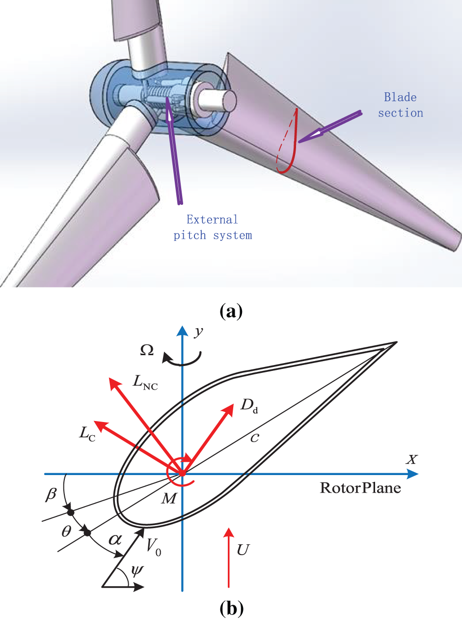
Figure 7: A wind turbine with three blades driven by the improved stall-induced nonlinear ONERA forces. (a) Turbine blade with external pitch driving; (b) The sectional coordinate system
3 Control Methods for Blade Vibration
The vibration control method of wind turbine blades refers to changing the shape, external structure, structural materials or installation methods of the blades, as well as adjusting the yaw angle, pitch angle or braking force of the blades to change the structural damping or attenuate aerodynamic loads, in order to suppress vibration and improve the performance and service life of wind turbines. At present, there are countless studies on the vibration control of wind turbine blades, mainly divided into passive control and active control. Fig. 8 presents the components of the vibration control of wind turbine blades.
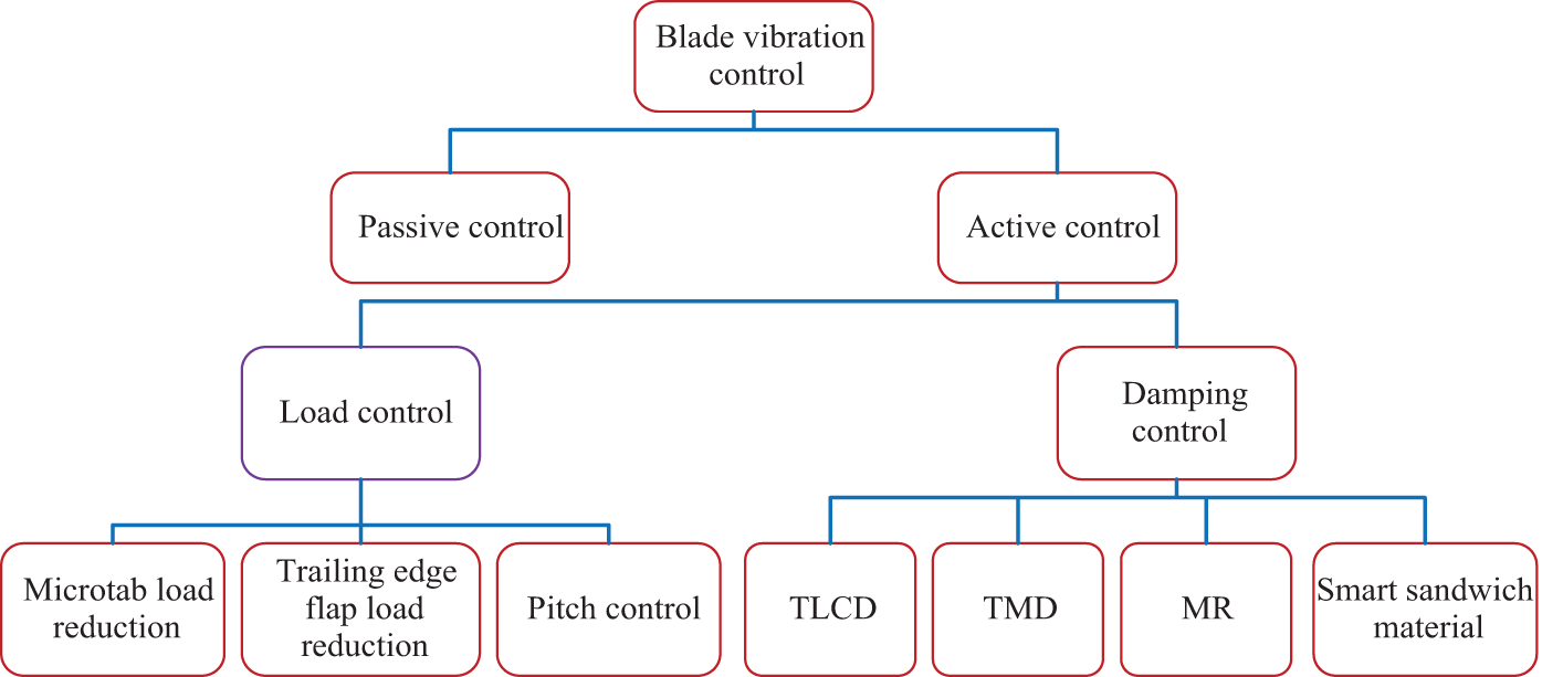
Figure 8: Classification of wind turbine blade vibration control
Passive control adjusts the quality and stiffness distribution of the blade structure, changes the damping and natural frequency of the blade to avoid coupling resonance with the system, or redesigns the blade structure and directly replaces the blade material to prevent blade flutter. This is a flutter suppression method based on passive damping.
Hayat et al. [120] attempted to improve the aeroelastic stability of wind turbines by changing the ply angle of the composite material on the blades to be smaller than the usual ply angle value. The calculation results for the NREL-5MW wind turbine model show that this method can improve the bending stiffness of the blades while reducing the torsional stiffness, resulting in a decrease in the critical flutter speed of the structure. Subsequently, Hayat et al. [121] adopted carbon fiber boards with lighter weight and higher strength by changing the blade layer material. The calculation results show that the critical flutter speed of the wind turbine can be increased by 7.6%–9.5%. Larwood et al. [122] studied the flutter characteristics of an NREL-5MW wind turbine with swept blades. The main difference between swept blades and traditional blades is that their elastic axis is curved, and the results show that the vibration suppression effect can be improved to a certain extent. However, this type of swept back blade not only enhances flutter suppression capability, but also brings serious fatigue problems. Li et al. and Sun et al. [123,124] improved the damping of the blade structure and achieved the effect of suppressing flutter by pasting damping layers in the blade layup plate and box beam chambers, as well as adding damping layers to the sandwich material of the blade. Due to the close relationship between blade flutter and aerodynamic, gravity, structure damping, and elastic forces, Kong et al. and Qian et al. [125,126] designed new blade profiles to prevent flutter by adjusting the center of gravity position, increase torsional stiffness and edge structure damping, and meeting processing technic requirements. By adjusting the first-order torsional frequency of the blades, they avoided the problem of coupled flutter of the blades. Zhang et al. [127] designed a blade with multi-layer constrained damping to prevent flutter. Compared with single-layer constrained damping blades and ordinary blades, this type of blade structure has higher structural damping and better vibration suppression performance, which can provide necessary guidance and reference for the vibration suppression design of large wind turbines. Sun et al. [128] achieved passive aeroelastic coupling of wind turbine blades by introducing bending torsional coupling and geometric sweep coupling to reduce loads. The first coupling is achieved by off-axis composite fibers of the blade spar cap, and the second coupling is achieved by defining the sweep curve of the blade reference axis. The results indicate that the two types of coupling of the blade can not only reduce the load at the root of the blade through a smaller off-axis angle of the optical fiber, but also further reduce the axial torque.
Passive damping of synchronous switch (PDSS) is also considered a promising solution to reduce the vibration of thin-walled structures of blades or plates. The common approach is to independently shunt the switch circuit to a single piezoelectric structure. Fan et al. [129] explored a new method of using PDSSs, in which PDSSs are interconnected between two piezoelectric structures or substructures, and conducted numerical and experimental studies on the damping mechanism, performance, and effective range of interconnected PDSSs. Firstly, based on the FE model of the double cantilever beam, the time-domain and frequency-domain modeling and solving methods of the interconnected PDSSs were derived and verified. Then, the influence of amplitude and phase relationship on the damping effect of interconnected PDSSs was numerically studied. This passive damping suppression has positive promotional significance, and it is actually a critical damping control (CDC) scheme. As long as an effective external active control scheme is configured, active control can be achieved. Of course, further updates are needed for piezoelectric materials, such as switching to flexible piezoelectric materials, which will be discussed in detail in the following sections of this article. Sajeer et al. [130] investigated a rotating finite element model of blades, which features longitudinal reinforcement bars (i.e., steel strands along their length) made of shape memory alloy (SMA), forming passive damping control. The modal analysis of reinforced blades shows a significant increase in bending stiffness. This model also belongs to a type of CDC model, which can achieve active control as long as appropriate temperature control signals are added to SMA. Jahangiri et al. [131] proposed a two-dimensional nonlinear passive tuned-mass-damper (TMD) inertial instrument aimed at suppressing bidirectional vibration of blades in the edge and flap directions, which is also a type of CDC planning. This type of CDC planning considers both cost and technical requirements, as well as flutter suppression requirements, which is a compromise and has positive significance in aeroelastic control.
Active control is to suppress blade vibration by loading damping structures on the original blades or using advanced control strategies, mainly including load control and active damping control.
Load control improves the aerodynamic stability of wind turbine blades by changing the aerodynamic load on the blades. Load control mainly includes control schemes such as microtab load reduction, trailing edge flap (TEF) load reduction, and pitch control, as well as other active load control schemes.
(1) Microtab and TEF
In recent years, many scholars have studied the unloading methods of wind turbine blades based on microtab structures. Macquart et al. and Ballesteros-Coll et al. [132,133] investigated the load reduction effect of the microtab techniques based on various intelligent control theories and CFD analysis methods. Calculation results show that: the airfoil lift base on microtab is within the normal working range of the airfoil, beyond the normal working range, the lift will be reduced. At the same time as changing the circulation of the airfoil, there is an increase in drag resistance. Therefore, in deep stall vibration, it may have a negative effect. Ballesteros-Coll et al. [133] also first studied the performance and effects of a rotating microtab implemented at the trailing edge of the DU91W250 airfoil using a novel cell-set model (CSM) based on CFD analysis. Fig. 9 presents the sketch of the DU91W250 airfoil and the rotating CSM microtab in reference [133]: βc is the angle between the axis and microtab and h is the length of the microtab. This CSM method is based on the flow control device modeling and the reuse of calculated grids and the addition of new geometric shapes, which is fully suitable for the calculation and testing of the geometric shape of trailing rotating microtabs. In addition, many scholars have studied the flexible TEF-based methods just mentioned for load control in recent years. Due to the fact that the leading-edge slats can increase the flow energy on the suction surface of the airfoil, while microtab can impede the flow on the pressure surface. In order to combine the advantages of two flow control methods, Li et al. [134] proposed to combine leading edge slats with microtab to simulate the planning of S809 airfoil, and used a transitional ‘Shear Stress Transport’ turbulence model to estimate the aerodynamic characteristics of S809 airfoil. Microtab can also be combined with subsequent TEFs to improve the performance of wind turbine blades, as it can generate greater lift and delay the occurrence of stall. Ye et al. [135] focused on the combination way using NREL’s S809 as the model airfoil in wind turbine blades. The results showed that due to the opposite direction of vortices, the maximum lift coefficient increased by 25% and the airflow stall was delayed, which was significantly better than the testing of standard airfoils.
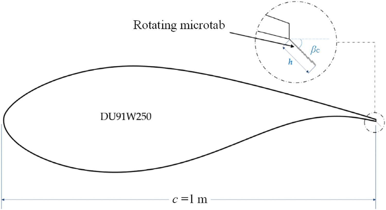
Figure 9: Sketch of the DU91W250 airfoil and the rotating CSM microtab in Reference [133]. Copyright ©2021, Alejandro Ballesteros-Coll et al. βc is the angle between the axis and microtab and h is the length of the microtab
Huang et al. [136] investigated the mechanism of how and to what extent flap deflection affects the blade tip vortex system using TEFs and cross-center flaps (deflected in opposite directions so that the blade root bending moment remains almost constant) to excite the instability pattern of the blade tip vortex system. Thakur et al. [137] studied the load reduction effect of blade TEFs under turbulent flow, using BEM theory to obtain aerodynamic loads by modeling in the framework of multi-body theory and dynamical analysis in the framework of a FE method. Zhuang et al. [138] verified and analyzed in detail the role of three parameters, deflection, amplitude, and phase shift, in the control of TEFs against aerodynamic loads by CFD models. Liu [139] calibrated an aerodynamic load calculation method for rigid TEFs and realized the control of the blade tip displacement using a sliding mode control method. For flexible TEFs of torsional blades, a downward offset TEF produces a pitch motion and thus (potentially) reduces the load, while an upward offset has the opposite effect, so it must rely on an active external pitch control algorithm or an additional hardware solution design. Liu et al. [140] used a thin-walled structure using CAS-based composite configuration, with rigid TEF embedded and hinged into the host composite structure along the entire blade span, to realize vibration control based on the restricted control input signals.
In addition, multiple TEFs can be folded and used to form a multi-elements trailing edge (METE), which involves the concept of morphable blades. Redonnet et al. [141] explored the idea of deformable turbine blades. Fig. 10 shows the concept of wind turbine blade morphing based on METE from reference [141]. Using different degrees of deformation, the authors evaluated the aerodynamics of representative deformable wind turbine blade cross-sections using numerical simulations. The experiment in reference [141] also showed that these deformation strategies have significant benefits, including not only a significant increase in power delivered in all flow states, but also further confirming the aerodynamic advantages brought by deformation.
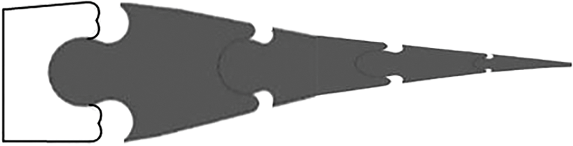
Figure 10: Wind turbine blade morphing concept based on METE
In addition, vertical axis wind turbines can also achieve load control based on an additional structure called “edge”. Vel et al. [142] investigated the impact of aerodynamic characteristics changes caused by incorporating leading edge protrusion blades into wind turbines at different wind speeds on structural response, and studied in detail the unsteady structural excitation caused by vortex attenuation under different aerodynamic loads and its effect on wind turbine structures. There are other additional structures assembled on the blades that can also achieve load control. For instance, Martín-Alcántara et al. [143] conducted an exploratory evaluation of the applicability of micro-cylinder devices in reducing vortex induced vibration of wind turbine blades under small cross flow conditions. The deep stall behavior of NACA0021 was evaluated at high angles of attack through CFD evaluation, and the influence of micro-cylinders on reducing the amplitude and fluctuation of aerodynamic coefficients was studied.
The forms of TEFs need to be specifically explained. The TEFs can commonly be constructed in two forms, one is a local flap, and the other is a large-span structure in the span direction (See Fig. 11). The local flaps are often rigid and suitable for high stiffness airfoils; The large-span flaps are often flexible and suitable for flexible composite blade materials. The combination of TEF and pitch control not only fully utilizes the advantages of TEF, but also overcomes the disadvantages of pitch control. Combined with the comprehensive application of the intelligent control theories, it has positive significance in reducing blade load and vibration.
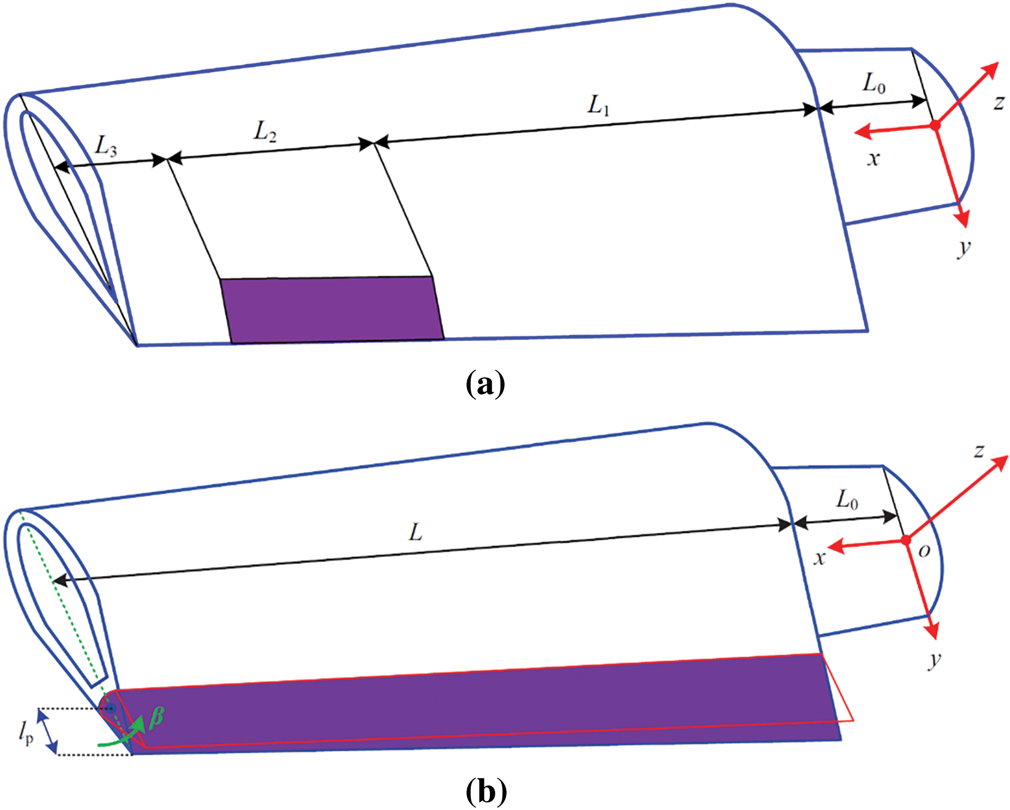
Figure 11: The TEFs constructed in two forms. (a) A local flap structure; Turbine blade with external pitch driving; (b) The sectional coordinate system; A large-span flap structure
(2) Pitch control
Pitch control, although commonly used as the best power control scheme, also had a positive effect on load control of wind turbines as the earliest aeroelastic control method. Yuan et al. [144] developed a multivariable, robust, independent pitch control framework and explicitly modeled the coupling between blades to provide frequency domain response characteristics. They also adopted a structural singular value μ-synthesis strategy to reduce periodic loads. Chen et al. [145] developed a real-time feedback pitch control system based on real-time flow velocity around the blade through in-depth aerodynamic analysis of the relationship between pitch angle and blade performance. They also constructed a CFD method based on FLUENT to evaluate the performance of the pitch control system in improving blade performance. Zhou et al. [146] investigated some control schemes based on individual pitch control, including blade damping control, linear quadratic gaussian (LQG) control, H∞ control, and improved LQG control with optimal disturbance observer. At the same time, the specific process of controller design was given, and these algorithms were effectively verified through simulation.
However, with the increasing size of wind turbine blades, considering factors such as blade weight, reverse impact, stall effect at extreme wind speeds, and hydraulic pitch lag, the reliability control defects of pitch control technology have significantly increased. Therefore, it is not used as an independent load shedding technology for large wind turbine blades under “extreme wind conditions”.
Damping control is widely used in large structures. For wind turbines, the damping control method adopts the installation of damping devices or the laying of layered structures with third-party materials combined with external active control planning to suppress the vibration of wind turbine blades. According to the dynamic equation, additional control force is applied to reduce vibration. At present, the technologies that are relatively mature and widely used include frequency modulated liquid dampers (i.e., the Tuned Liquid Column Damper, TLCD), frequency modulated TMD, magnetorheological (MR) dampers, fused blade tip constructions (FBTC), and smart sandwich material damping control. Although various damper controls belong to structural damping control, they often use various intelligent control theories to improve the effectiveness of damping control, which also has positive significance.
(1) TLCD and TMD methods
Zhang et al. [147] installed roller dampers at specific locations on the blades to reduce in-plane vibrations, and proposed three different roller layouts where the vibration energy of the blades is absorbed by balls, cylinders, or flywheels that roll in a circular tube. Among them, the flywheel has a larger mass moment of inertia, but its layout compactness is lower than that of a sphere or cylinder with the same mass. Afterwards, Zhang et al. [148] installed TLCD to enhance the damping of the blades in the direction of rotation plane. The results indicate that better control effects can be achieved by increasing the mass ratio and installing the damper closer to the blade tip. Other new TLCD studies include: Basu et al. [149] used a cylindrical TLCD filled with liquid that can move back and forth in the tube; Chen et al. [145] studied the installation of a novel frequency modulation damper inside the blade to improve the critical conditions of blade vibration. The results indicate that these new frequency modulation dampers can increase the critical speed of blade flutter by 100%.
Fitzgerald et al. [150] used a pre-tensioned cable to connect the active TMD inside the blade and the blade tip, further reducing the response of the blade in the in-plane direction. The system fully considers the structural dynamics of the system, the interaction between in-plane and out of plane vibrations, and the mutual influence between the blades and tower, significantly reducing the in-plane vibration of large flexible wind turbine blades. Sonkusare et al. [151] utilized piezoelectric tuned TMD to achieve active control of edge vibration of a pre-twisted beam rotating in a vertical plane. The TMD consists of a spring mass damper system, a piezoelectric transducer, and its related shunt circuit. By investigating the peak and root mean square values of the beam tip response, the optimal values of resistance and inductance for the shunt circuit were obtained.
(2) Other active damping control methods
Chen et al. [152] used MR to provide control force, and the controllable fluid of the MR damper can change from a free flow state to a semi-solid state when a magnetic field is involved, in order to reduce the in-plane vibration of the blade. Dai Y et al. [153] proposed a FBTC scheme. The FBTC structure allows for adjusting the folding angle of the blade tip. The authors investigated the impact of FBTC structure on the aerodynamics of wind turbines by comparing numerical simulations and experimental tests. The research results indicate that the FBTC structure enhances the aerodynamic performance of wind turbines. Not only does it increase the turbulent kinetic energy and average pressure of the blade cross-section, but it also confirms that the blade tip folding angle can effectively optimize the aerodynamic performance of the turbine. In addition, Liu et al. [154] embedded a flexible piezoelectric (FP) material in the blades and improved the flutter suppression ability of the blades through optimal control methods. The advantage of this smart sandwich material damping control is that it has little coupling effect with variable pitch operation, and can operate independently of speed and power regulation without changing the aerodynamic force of the blades.
Safaeinejad et al. [155] proposed an active mitigation control method to reduce torsional and edge vibrations in wind turbines. This active control is based on the design of an extended dynamic model with mechanical structural flexibility, which adds an axillary term proportional to the speed difference between the blade and the hub to the power control loop. It is an intelligent control theory method based on sliding mode observer. Corral et al. [156] achieved intentional and asymptotic detuning modes in the rotor by installing small mass blocks on the tip cover of the blade. Through this mode, flutter can not only be suppressed but also modulated. Kandil et al. [157] applied time-delay and positive position feedback controllers to reduce nonlinear oscillations in rotating blade power systems. This is a nonlinear dynamic method with strong linear coupling and multiple time scales, suitable for nonlinear flutter suppression. Rafiee et al. [158] conducted a comprehensive review of academic articles published in the past few decades on rotating composite beams. This review involves analytical, semi-analytical, and numerical research, covering dynamic issues such as adaptive/intelligent/smart materials (such as piezoelectric materials, electrorheological fluids, SMAs, etc.), damping and vibration control, advanced composite materials (such as functionally graded materials and nanocomposites), complex effects and loads (such as added mass, conical beams, initial curves, and distortions), and experimental methods. This literature is an excellent one that can provide reference methods for various active damping control of wind turbine blades.
(3) Discussion on active damping control based on smart sandwich material
The implementation of smart sandwich material damping control using piezoelectric actuation relies on the combination of optimization control methods and active boundary element feedback control [154]. When using certain FP materials [159–161] instead of conventional rigid piezoelectric ceramic materials, it can not only suppress classical flutter but also stall flutter, provided that the piezoelectric material is flexible and has a considerable piezoelectric effect. The longitudinal 3-3 direction piezoelectric effect of this type of FP material is even better than the opposite 3-1 direction piezoelectric effect [162–164]. Fig. 12 shows the composite material host structure with the FP material pairs embedded. The piezoelectric material pairs consist of a sensor and an actuator. The sensor patch receives the piezoelectric signal caused by the deformation of the composite material host, and through active feedback control planning G, reacts with the actuator to excite the host to deform in the opposite direction, achieving the goal of suppressing flutter amplitudes. Because it is a FP material, there can be longer layers along the longitudinal span direction, and a larger width in the cross-sectional direction to improve damping effect and enhance feedback control effect.
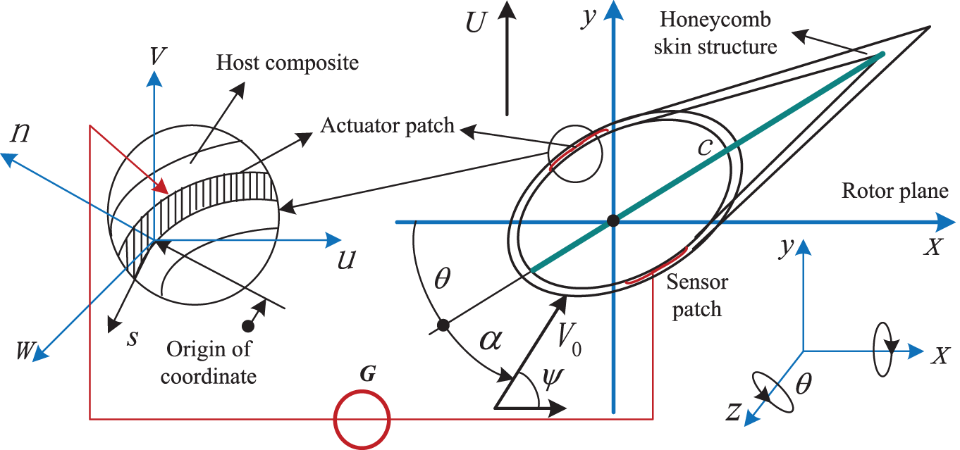
Figure 12: The composite material host structure with the FP material pairs embedded to suppress the stall-induced flutter
In addition, the real-time control of wind power systems is also a complex issue. After decoupling the system equations of composite blades, dozens of discretized variables will appear, making the vibration control problem more complex. When high-end intelligent control algorithms are used to achieve the active vibration control, due to the complexity of the algorithms, it is almost impossible to implement them in actual controller hardware, not to mention that most current wind power system controls use PLC controller hardware that has limitations in random-access memory and programming. An experimental platform [165] based on the OLE (Object Linking and Embedding) for process control (OPC) precisely solves this problem, which is an OPC Data Access technology.
3.2.3 Discussion on a Special HFMV Phenomenon and the Vibration Control Methods
In practice, it has been found that a large or medium-sized wind turbine under “normal operating conditions” will form a certain HFMV phenomenon when the excitation frequency is close to a certain high-order (within 5th order) natural frequency. Due to long-term excitation of blades under nonlinear high-frequency and small amplitude vibration conditions, implicit crack defects (or loosening and misalignment within the skin structure) may form in composite blades, making the blade body more prone to fracture failure under high wind speed flutter conditions or extreme working conditions. Zhang et al. [166] also noted that turbulent winds lead to an increase in aerodynamic loads and equivalent fatigue loads, resulting in low amplitude high-frequency vibrations in the flapping direction that have more destructive effects. Based on the study of the overall machine mode, Zhou et al. [146] confirmed the possible small amplitude and constant amplitude high-frequency vibration phenomena of linear vibration blades under conventional operating conditions. Linear quadratic control and H∞ control were used to suppress the linear flutter.
This HFMV phenomenon belongs to a type of coupled motion, exhibiting a coupled bending-twist(torsional) displacement. Bending displacement refers to the displacement in the y-direction of (See Fig. 13a), while twist displacement is denoted by θ. At this point, the above-mentioned FP materials can precisely play a role. The piezoelectric layer does not need to be too long, it only needs to be laid inside the composite material host near the blade root, as shown in Fig. 12. Of course, the piezoelectric layer does not need to be too wide, so the FP material at this time can be replaced by rigid piezoelectric ceramic material. The small sized piezoelectric layers also need to be layered in pairs up and down, but there is no need to use feedback control between the upper and lower layers. Instead, the active control method shown in Fig. 13b can be used instead. After obtaining the piezoelectric signals from the upper and lower layers, perform absolute value operations and add them together. Then, after passing through an amplifier, obtain the signal G that can be recognized by the physical controller hardware. When HFMV lasts for a period of time t and G stabilizes within a certain set range, the physical controller issues a command to drive the pitch motion. The pitch motion is arbitrary, as long as the system avoids the resonance region, so that HFMV can be suppressed.
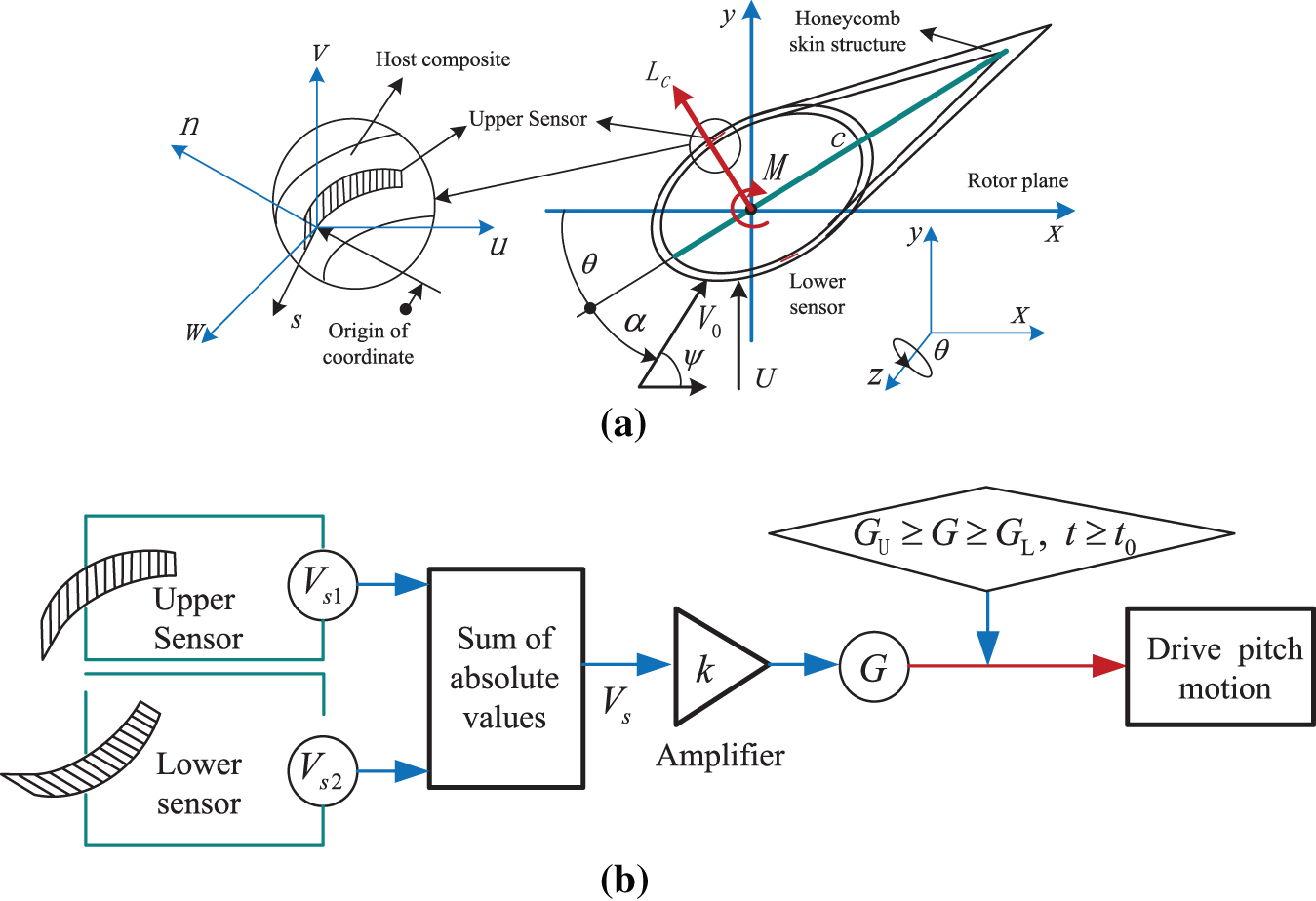
Figure 13: The small sized piezoelectric layup and control planning in composite material host. (a) Small sized piezoelectric layer patches; (b) Active control method
It should be noted that this HFMV phenomenon can also occur in the three-bladed system of small wind turbines when the wind speed is less than 6 m/s. However, regardless of the type of wind turbine blades, detecting small defects caused by HFMV based on commercial sensors is quite difficult. The adaptive positioning technology based on laser optical scanning can scan the point cloud data of the entire blade surface [167] to obtain the position of micro defects, or directly scan the surface to obtain the crack information of micro defects. However, both the operation process and the detection technology itself are very complex and difficult to implement in engineering applications. Therefore, it is very important to prevent the occurrence of HFMV in advance and take preventive measures. At the same time, it is essential to use miniature models and laser displacement sensors (DSs) to perfectly match real wind turbines and conduct in-depth research on HFMV phenomena. In order to overcome the problem of poor aerodynamic performance of micro-models caused by miniature effects, Yang et al. [168] proposed an innovative blade design method based on machine learning for miniature model testing. Wind tunnel tests have shown that this method achieves satisfactory similarity between thrust and power coefficients under various operating conditions of the miniature model and prototype and achieves perfect matching in the study of NREL-5MW wind turbines. The miniature models of this type of structure, when combined with laser DSs, will achieve ideal results in HFMV phenomenon research. Fig. 14 shows the miniature model of the structure and laser DSs layout from reference [168].
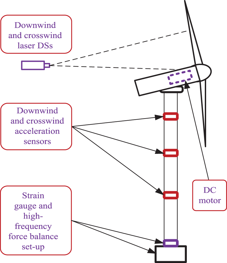
Figure 14: The miniature model of the structure and laser DSs layout
In the present study, a detailed review and discussion were conducted on the modeling and vibration control of aeroelastic systems of composite blades. At present, significant progress has been made in aeroelastic system modeling and vibration control technology of wind turbine blades, but there are still many problems that urgently need to be solved, as it not only involves issues of aeroelasticity and aerodynamics, but also involves the advanced fields of control and computer science. For example, the accuracy of modeling needs to be further improved, and vibration control methods need to be optimized for the flexible characteristics of large turbine blades to be combined with advanced control algorithms. Therefore, control accuracy and reliability are also important research topics to achieve better control effects. Therefore, further in-depth research is needed in the modeling and vibration control of wind turbine blades to promote the sustainable development of wind energy. The research themes can be outlined as follows:
(1) Refined dynamic models need to be established, coupling the dynamic model of the blade with wind, tower and other factors more reasonably in view of the influence of aerodynamic, structural, temperature, electromagnetic and other factors of the blade on its dynamic characteristics. Furthermore, the more refined dynamic models should be established to predict, more accurately, the dynamic responses of blades to improve performance and reliability.
(2) The new blade materials and structures need to be developed. It is advisable to design efficient, lightweight, and high-strength blade structures using multi-objective optimization, topology optimization, multi-scale optimization, and other methods based on different wind field conditions and requirements. By exploring the performance of rigid and ductile materials, efforts should be made to find better blade materials and structures, improve the toughness and stiffness of blades, and enhance wind energy utilization efficiency.
(3) The mechanisms of brittle fracture and fatigue failure of blades should be investigated, using sensor testing, signal processing, machine learning and other methods to detect the status and damage of blades in real time, detecting and predicting blade damage as early as possible, and predicting the health status and maintenance needs of blades to improve the service life of blades.
(4) Various intelligent control algorithms should be introduced to actively control the vibration of blades. With the development of high-performance intelligent algorithms, they can be applied to active vibration control planning of blades to generate more stable and efficient outputs for wind turbines. For example, the FP material mentioned in this article not only has flexibility, but its piezoelectric properties are not weaker than, or even surpass, conventional rigid piezoelectric ceramic material [162–164], so it has scientific value for further in-depth research. If there is an effective intelligent control algorithm for matching, active feedback control will demonstrate more outstanding results.
(5) At the same time, more efficient smart sandwich materials can be introduced and embedded into the composite material host to improve the performance of active control. For instance, due to the different vibration properties of SMA under high and low temperature transformation conditions [169], the Brinson model analysis based on high-order layering theory and SMA phase transition constitutive relationship is used to analyze the thermoelastic coupling nonlinear FE model of laminated composite beams with active SMA layers, which is often applied in composite material beam structures to achieve flutter suppression [170–172]. Therefore, we envision that we can apply the same planning to wing structures instead of beam structures, and use various intelligent control theories as assistance, which will open up more effective ways to achieve active control of composite blades.
(6) With the introduction of service-oriented architecture in manufacturing systems, the demand for cross platform data transmission and the issue of data security for large-scale data transmission are becoming increasingly critical. The OPC Data Access technology mentioned above seems somewhat powerless now. An Open Platform Communications Unified Architecture (OPC UA) technology [173–175] is capable of performing this job as it is a service-oriented communication protocol that enables interoperability between various hardware systems and devices. This is an unavoidable research field in the real-time control of wind power systems in the future.
(7) It should be noted that the deficiencies listed in this article do not specifically refer to the shortcomings of the cited literature, as they are common deficiencies in blade aeroelasticity and vibration control in the field of wind power generation. Therefore, the goal of this article is to identify and analyze these issues and explore the possible solutions. Sincere thanks to all the authors of the cited literature.
Acknowledgement: None.
Funding Statement: The authors disclosed receipt of the following financial support for the research, authorship, and/or publication of this article: This research is supported by the Natural Science Foundation of Shandong Provincial of China (Grant Number ZR2022ME093); the Natural Science Foundation of China (Grant Number 51675315).
Author Contributions: The authors confirm contribution to the paper as follows: study conception and design: Tingrui Liu, Qinghu Cui; analysis and interpretation of results: Dan Xu, Qinghu Cui; graphics and curves: Tingrui Liu, Dan Xu. All authors reviewed the results and approved the final version of the manuscript.
Availability of Data and Materials: All data are included in this published article.
Ethics Approval: Not applicable.
Conflicts of Interest: The authors declare no conflicts of interest to report regarding the present study.
References
1. Kaewniam P, Cao M, Alkayem NF. Recent advances in damage detection of wind turbine blades: a state-of-the-art review. Renew Sust Energ Rev. 2022;167:112723. doi:10.1016/j.rser.2022.112723. [Google Scholar] [CrossRef]
2. Yang XJ, Hu H, Tan T, Li J. China’s renewable energy goals by 2050. Environ Dev. 2016;20:83–90. doi:10.1016/j.envdev.2016.10.001. [Google Scholar] [CrossRef]
3. Verma AS, Yan J, Hu W, Jiang Z, Shi W, Teuwen JJ. A review of impact loads on composite wind turbine blades: impact threats and classification. Renew Sust Energ Rev. 2023;178:113261. doi:10.1016/j.rser.2023.113261. [Google Scholar] [CrossRef]
4. Hu W, Choi KK, Olesya Z, Buchholz-James HJ. Integrating variable wind load, aerodynamic, and structural analyses towards accurate fatigue life prediction in composite wind turbine blades. Struct Multidiscip Optim. 2016;53(3):375–94. [Google Scholar]
5. Alejandro A, Nadia R, Facundo B, Victor F. A metamodel-based optimization approach to reduce the weight of composite laminated wind turbine blades. Compos Struct. 2018;194:345–56. [Google Scholar]
6. Bossanyi E. GH Bladed theory manual. Bristol, UK: GH & Partners Ltd.; 2013. [Google Scholar]
7. Manolas DI, Riziotis VA, Voutsinas SG. Assessing the importance of geometric nonlinear effects in the prediction of wind turbine blade loads. J Comput Nonlinear Dynam. 2015;10(4):041008. doi:10.1115/1.4027684. [Google Scholar] [CrossRef]
8. Wang Q, Sprague MA, Jonkman J, Johnson N, Jonkman B. BeamDyn: a high-fidelity wind turbine blade solver in the FAST modular framework. Wind Energy. 2015;20(8):1439–62. doi:10.1002/we.2101. [Google Scholar] [CrossRef]
9. Mo WW, Li DY, Wang XN, Zhong CT. Aeroelastic coupling analysis of the flexible blade of a wind turbine. Energy. 2015;89:1001–9. doi:10.1016/j.energy.2015.06.046. [Google Scholar] [CrossRef]
10. Luo K, Zhang S, Gao Z, Wang J, Zhang L, Yuan R, et al. Large-eddy simulation and wind-tunnel measurement of aerodynamics and aeroacoustics of a horizontal-axis wind turbine. Renew Energ. 2015;77:351–62. doi:10.1016/j.renene.2014.12.024. [Google Scholar] [CrossRef]
11. Li Y, Yang S, Feng F, Tagawa K. A review on numerical simulation based on CFD technology of aerodynamic characteristics of straight-bladed vertical axis wind turbines. Energ Rep. 2023;9:4360–79. doi:10.1016/j.egyr.2023.03.082. [Google Scholar] [CrossRef]
12. Gao R, Yang J, Yang H, Wang X. Wind-tunnel experimental study on aeroelastic response of flexible wind turbine blades under different wind conditions. Renew Energ. 2023;219(2):119539. doi:10.1016/j.renene.2023.119539. [Google Scholar] [CrossRef]
13. Zhou JW, Qin Z, Zhai E, Liu Z, Wang S, Liu Y, et al. Bend-twist adaptive control for flexible wind turbine blades: principles and experimental validation. Mech Syst Signal Pr. 2025;224:111981. doi:10.1016/j.ymssp2024.111981. [Google Scholar] [CrossRef]
14. Shakya P, Sunny MR, Maiti DK. Nonlinear flutter analysis of a bend-twist coupled composite wind turbine blade in time domain. Compos Struct. 2022;284:115216. doi:10.1016/j.compstruct2022.115216. [Google Scholar] [CrossRef]
15. Lu MM, Ke ST, Wu HX, Gao ME, Tian WX, Wang H. A novel forecasting method of flutter critical wind speed for the 15 MW wind turbine blade based on aeroelastic wind tunnel test. J Wind Eng Ind Aerod. 2022;230:105195. doi:10.1016/j.jweia.2022.105195. [Google Scholar] [CrossRef]
16. Xu J, Zhang L, Li X, Li S, Yang K. A study of dynamic response of a wind turbine blade based on the multi-body dynamics method. Renew Energ. 2020;155:358–68. doi:10.1016/j.renene.2020.03.103. [Google Scholar] [CrossRef]
17. Lang Q, Zheng Y, Cui T, Shi C, Zhang H. Nonlinear Flap-wise vibration characteristics of wind turbine blades based on multi-scale analysis method. Energ Eng. 2024;121(2):483–98. doi:10.32604/ee.2023.042437. [Google Scholar] [CrossRef]
18. Shakya P, Thomas M, Seibi AC, Shekaramiz M, Masoum MS. Fluid-structure interaction and life prediction of small-scale damaged horizontal axis wind turbine blades. Result Eng. 2024;23:102388. doi:10.1016/j.rineng.2024.102388. [Google Scholar] [CrossRef]
19. Keflemariam YA, Lee S. Control and dynamic analysis of a 10 MW floating wind turbine on a TetraSpar multi-body platform. Renew Energ. 2023;217:119194. doi:10.1016/j.renene.2023.119194. [Google Scholar] [CrossRef]
20. Du Y, Zhou S, Jing X, Peng Y, Wu H, Kwok N. Damage detection techniques for wind turbine blades: a review. Mech Syst Signal Pr. 2020;141:106445. doi:10.1016/j.ymssp.2019.106445. [Google Scholar] [CrossRef]
21. Kong K, Dyer K, Payne C, Hamerton I, Weaver PM. Progress and trends in damage detection methods, aintenance, and data-driven monitoring of wind turbine blades—a review. Renew Energ Focus. 2023;44:390–412. doi:10.1016/j.ref.2022.08.005. [Google Scholar] [CrossRef]
22. Bauchau OA, Craig JI. Euler-Bernoulli beam theory. In: Bauchau OA, Craig JI, editors. Structural analysis. Holland, Dordrecht: Springer; 2009. vol. 163, p. 173–221. doi:10.1007/978-90-481-2516-6_5. [Google Scholar] [CrossRef]
23. Algolfat A, Wang W, Albarbar A. Comparison of beam theories for characterisation of a NREL wind turbine blade flap-wise vibration. P I Mech Eng A-J Pow. 2022;236(7):1350–69. doi:10.1177/09576509221089146. [Google Scholar] [CrossRef]
24. Zhang Y. Research on vibration and flutter characteristics of large wind turbine blade (Ph.D. Thesis). North China Electric Power University: China; 2022. [Google Scholar]
25. Hodges DH. Geometrically exact, intrinsic theory for dynamics of curved and twisted anisotropic beams. AIAA J. 2003;41(6):1131–7. doi:10.2514/2.2054. [Google Scholar] [CrossRef]
26. Wang Z, Lu Z, Yi W, Hao J, Chen Y. A study of nonlinear aeroelastic response of a long flexible blade for the horizontal axis wind turbine. Ocean Eng. 2023;279:113660. doi:10.1016/j.oceaneng.2023.113660. [Google Scholar] [CrossRef]
27. Zhao X, Jiang X, Zhu W, Li J. Semi-analytical solutions for steady-state bending-bending coupled forced vibrations of a rotating wind turbine blade by means of Green’s functions. J Sound Vib. 2024;596:118714. doi:10.1016/j.jsv.2024.118714. [Google Scholar] [CrossRef]
28. Guan H, Ni K, Ma H, Xiong Q, Wang W, Wang H. Dynamic modeling and verification of rotating compressor blade with crack based on beam element. Appl Math Model. 2024;133:367–93. doi:10.1016/j.apm.2024.05.019. [Google Scholar] [CrossRef]
29. Fudlailah P, Allen DH, Cordes R. Verification of Euler-Bernoulli beam theory model for wind blade structure analysis. Thin Wall Struct. 2024;202:111989. doi:10.1016/j.tws.2024.111989. [Google Scholar] [CrossRef]
30. Khabiri A, Asgari A, Taghipour R, Bozorgnasab M, Aftabi-Sani A, Jafari H. Analysis of fractional Euler-Bernoulli bending beams using Green’s function method. Alex Eng J. 2024;106:312–27. doi:10.1016/j.aej.2024.07.023. [Google Scholar] [CrossRef]
31. Krysko AV, Awrejcewicz J, Pavlov SP, Bodyagina KS, Zhigalov MV, Krysko VA. Non-linear dynamics of size-dependent Euler-Bernoulli beams with topologically optimized microstructure and subjected to temperature field. Int J Nonlin Mech. 2018;104:75–86. doi:10.1016/j.ijnonlinmec.2018.05.008. [Google Scholar] [CrossRef]
32. Malik S, Singh DK, Bansal G, Paliwal V, Manral AR. Finite element analysis of Euler’s Bernoulli cantilever composite beam under uniformly distributed load at elevated temperature. Mater Today: Proc. 2021;46(20):10725–31. doi:10.1016/j.matpr.2021.01.548. [Google Scholar] [CrossRef]
33. Hamdi H, Mrad C, Hamdi A, Nasri R. Dynamic response of a horizontal axis wind turbine blade under aerodynamic, gravity and gyroscopic effects. Appl Acoust. 2014;86:154–64. doi:10.1016/j.apacoust.2014.04.017. [Google Scholar] [CrossRef]
34. Horcas SG, Debrabandere F, Tartinville B, Hirsch C, Coussement G. Extension of the non-linear harmonic method for the study of the dynamic aeroelasticity of horizontal axis wind turbines. J Fluid Struct. 2017;73:100–24. doi:10.1016/j.jfluidstructs.2017.06.008. [Google Scholar] [CrossRef]
35. Rezaei MM, Zohoor H, Haddadpour H. Aeroelastic modeling and dynamic analysis of a wind turbine rotor by considering geometric nonlinearities. J Sound Vib. 2018;432:653–79. doi:10.1016/j.jsv.2018.06.063. [Google Scholar] [CrossRef]
36. Yang X, Shen Y, Li H. Finite element analysis on structural mechanical characteristics of the 5 MW wind turbine blade. Mech Res Appl. 2018;31(4):42–5 (In Chinese). [Google Scholar]
37. Wang H, Miao WP, Li C, Zhang L, Zhu H. Structural characteristic analysis of new type bend-twist coupling blades of large wind turbine. J Mech Strength. 2024;46(3):6685–74 (In Chinese). [Google Scholar]
38. Liu JW, Liu PF, Leng JX, Wang CZ. Finite element analysis of damage mechanisms of composite wind turbine blade by considering fluid/solid interaction. Part I: full-scale structure. Compos Struct. 2022;301:116212. doi:10.1016/j.compstruct.2022.116212. [Google Scholar] [CrossRef]
39. Liu PF, Liu JW, Wang CZ. Finite element analysis of damage mechanisms of composite wind turbine blade by considering fluid/solid interaction. Part II: t-shape adhesive structure. Compos Struct. 2022;301:116211. doi:10.1016/j.compstruct.2022.116211. [Google Scholar] [CrossRef]
40. Yan Z, Rahimizadeh A, Zhang Y, Zhou Y, Lessard L. A finite element model for 3D printed recycled parts from end-of-life wind turbine blades. Compos Struct. 2023;320:117177. doi:10.1016/j.compstruct.2023.117177. [Google Scholar] [CrossRef]
41. Dao MH, Le QT, Zhao X, Ooi CC, Duong LT, Raghavan N. Modelling of aero-mechanical response of wind turbine blade with damages by computational fluid dynamics, finite element analysis and Bayesian network. Renew Energ. 2024;227:120580. doi:10.1016/j.renene.2024.120580. [Google Scholar] [CrossRef]
42. Tavares RP, Bouwman V, Paepegem WV. Finite element analysis of wind turbine blades subjected to torsional loads: shell vs solid elements. Compos Struct. 2022;280:114905. doi:10.1016/j.compstruct.2021.114905. [Google Scholar] [CrossRef]
43. Peeters M, Santo G, Degroote J, Paepegem WV. High-fidelity finite element models of composite wind turbine blades with shell and solid elements. Compos Struct. 2018;200:521–31. doi:10.1016/j.compstruct.2018.05.091. [Google Scholar] [CrossRef]
44. Vaz J, Okulov VL, Wood DH. Finite blade functions and blade element optimization for diffuser-augmented wind turbines. Renew Energ. 2021;165(1):812–22. doi:10.1016/j.renene.2020.11.059. [Google Scholar] [CrossRef]
45. Dash AK, Prabhu J, Nagarajan V. Stochastic finite element analysis of composite cycloidal propeller blade during crash-stop ship maneuver. Compos Struct. 2022;286:115306. doi:10.1016/j.compstruct.2022.115306. [Google Scholar] [CrossRef]
46. Albanesi A, Fachinotti V, Peralta I, Storti B, Gebhardt C. Application of the inverse finite element method to design wind turbine blades. Compos Struct. 2017;161:160–72. doi:10.1016/j.compstruct.2016.11.039. [Google Scholar] [CrossRef]
47. Chakravarthy CHN, Kumar SS, Muthalagu R. Finite element modeling using carbon epoxy plates for propeller blades applications. Mater Today: Proc. 2021;44(6):3951–8. doi:10.1016/j.matpr.2020.09.639. [Google Scholar] [CrossRef]
48. Gebhardt CG, Roccia BA. Non-linear aeroelasticity: an approach to compute the response of three-blade large-scale horizontal-axis wind turbines. Renew Energ. 2014;66:495–514. doi:10.1016/j.renene.2013.12.040. [Google Scholar] [CrossRef]
49. Farsadi T, Rahmanian M, Kayran A. Geometrically nonlinear aeroelastic behavior of pretwisted composite wings modeled as thin walled beams. J Fluid Struct. 2018;83:259–92. doi:10.1016/j.jfluidstructs.2018.08.013. [Google Scholar] [CrossRef]
50. Wang X, Xia P, Masarati P. Active aeroelastic control of aircraft wings with piezo-composite. J Sound Vib. 2019;455:1–19. doi:10.1016/j.jsv.2019.04.035. [Google Scholar] [CrossRef]
51. Chandra R, Chopra I. Experimental-theoretical investigation of the vibration characteristics of rotating composite box beams. J Aircraft. 1992;29(4):657–64. doi:10.2514/3.46216. [Google Scholar] [CrossRef]
52. Glauert H. Aerodynamic theory. Aeronaut J. 1930;34(233):409–14. doi:10.1017/S0368393100114397. [Google Scholar] [CrossRef]
53. Shen WZ, Mikkelsen R, Sørensen JN, Bak C. Tip loss corrections for wind turbine computations. Wind Energ. 2005;8(4):457–75. doi:10.1002/(ISSN)1099-1824. [Google Scholar] [CrossRef]
54. Wood DH, Okulov VL, Bhattacharjee D. Direct calculation of wind turbine tip loss. Renew Energ. 2016;95:269–76. doi:10.1016/j.renene.2016.04.017. [Google Scholar] [CrossRef]
55. Koh WXM, Ng EYK. Effects of Reynolds number and different tip loss models on the accuracy of BEM applied to tidal turbines as compared to experiments. Ocean Eng. 2016;1(11):104–15. doi:10.1016/j.oceaneng.2015.10.042. [Google Scholar] [CrossRef]
56. Spall RE, Phillips WF, Pincock BB. Numerical analysis of multiple, thin-sail geometries based on Prandtl’s lifting-line theory. Comput Fluid. 2013;82:29–37. doi:10.1016/j.compfluid.2013.04.020. [Google Scholar] [CrossRef]
57. Ning A, Hayman G, Damiani R, Jonkman JM. Development and validation of a new blade element momentum skewed-wake model within aerodyn. In: 33rd Wind Energy Symposium, 2015 Jan 5–9; Kissimmee, FL, USA; p. 3–20. Available from: https://www.nrel.gov/docs/fy15osti/63217.pdf. [Google Scholar]
58. Wang Q, Xu Y, Xu JZ. A new stall delay model for HAWT based on Inviscid theory. In: Zhou Y, Liu Y, Huang L, Hodges D, editors. Fluid-structure-sound interactions and control. lecture notes in mechanical engineering. Berlin/Heidelberg, Germany: Springer; 2014. p. 363–8. doi:10.1007/978-3-642-40371-2_52. [Google Scholar] [CrossRef]
59. Dowler JL, Schmitz S. A solution-based stall delay model for horizontal-axis wind turbines. Wind Energ. 2015;18(10):1793–813. doi:10.1002/we.1791. [Google Scholar] [CrossRef]
60. Dumitrescu H, Frunzulică F, Cardoş V. Improved stall-delay model for horizontal-axis wind turbines. J Aircraft. 2013;50(1):315–9. doi:10.2514/1.C031873. [Google Scholar] [CrossRef]
61. Lanzafame R, Messina M. BEM theory: how to take into account the radial flow inside of a 1-D numerical code. Renew Energ. 2012;39(1):440–6. doi:10.1016/j.renene.2011.08.008. [Google Scholar] [CrossRef]
62. Laalej S, Bouatem A, AlMers A, Maani RE. Wind turbine performances prediction using BEM approach with Jonkman-Buhl brake state model coupled to CFD method. Mater Today: Proc. 2022;65(8):3829–38. doi:10.1016/j.matpr.2022.07.033. [Google Scholar] [CrossRef]
63. Mauro S, Lanzafame R, Messina M, Brusca S. On the importance of the root-to-hub adapter effects on HAWT performance: a CFD-BEM numerical investigation. Energy. 2023;275:127456. doi:10.1016/j.energy.2023.127456. [Google Scholar] [CrossRef]
64. Dai Y, Wang D, Liu X, Wu W. Optimized design of bio-inspired wind turbine blades. Fluid Dyn Mate Proc. 2024;20(7):1647–64. doi:10.32604/fdmp.2024.046158. [Google Scholar] [CrossRef]
65. Kolios A, Chahardehi A, Brennan F. Experimental determination of the overturning moment and net lateral force generated by a novel vertical axis wind turbine: experiment design under load uncertainty. Exp Tech. 2013;37(1):7–14. doi:10.1111/j.1747-1567.2011.00727.x. [Google Scholar] [CrossRef]
66. Yirtici O, Cengiz K, Ozgen S, Tuncer IH. Aerodynamic validation studies on the performance analysis of iced wind turbine blades. Comput Fluid. 2019;192:104271. doi:10.1016/j.compfluid.2019.104271. [Google Scholar] [CrossRef]
67. Boulamatsis AM, Barlas TK, Stapountzis H. Active control of wind turbines through varying blade tip sweep. Renew Energ. 2019;131:25–36. doi:10.1016/j.renene.2018.07.022. [Google Scholar] [CrossRef]
68. Wang L, Liu X, Renevier N, Stables M, Hall GM. Nonlinear aeroelastic modelling for wind turbine blades based on blade element momentum theory and geometrically exact beam theory. Energy. 2014;76:487–501. doi:10.1016/j.energy.2014.08.046. [Google Scholar] [CrossRef]
69. Özkan R, Genç MS. Aerodynamic design and optimization of a small-scale wind turbine blade using a novel artificial bee colony algorithm based on blade element momentum (ABC-BEM) theory. Energ Convers Manage. 2023;283:116937. doi:10.1016/j.enconman.2023.116937. [Google Scholar] [CrossRef]
70. Apsley DD, Stansby PK. Unsteady thrust on an oscillating wind turbine: comparison of blade-element momentum theory with actuator-line CFD. J Fluid Struct. 2020;98:103141. doi:10.1016/j.jfluidstructs.2020.103141. [Google Scholar] [CrossRef]
71. Sun C, Tian T, Zhu X, Hua O, Du Z. Investigation of the near wake of a horizontal-axis wind turbine model by dynamic mode decomposition. Energy. 2021;227:120418. doi:10.1016/j.energy.2021.120418. [Google Scholar] [CrossRef]
72. Pinto RN, Afzal A, D’Souza LV, Ansari Z, Mohammed Samee A. Computational fluid dynamics in turbomachinery: a review of state of the art. Arch Computat Methods Eng. 2017;24(3):467–79. doi:10.1007/s11831-016-9175-2. [Google Scholar] [CrossRef]
73. Yang H, Shen W, Xu H, Hong Z, Liu C. Prediction of the wind turbine performance by using BEM with airfoil data extracted from CFD. Renew Energ. 2014;70:107–15. doi:10.1016/j.renene.2014.05.002. [Google Scholar] [CrossRef]
74. Tummala A, Velamati RK, Sinha DK, Indraja V, Krishna VH. A review on small scale wind turbines. Renew Sust Energ Rev. 2016;56:1351–71. doi:10.1016/j.rser.2015.12.027. [Google Scholar] [CrossRef]
75. Liu Z, Wang X, Kang S. Stochastic performance evaluation of horizontal axis wind turbine blades using non-deterministic CFD simulations. Energy. 2014;73:126–36. doi:10.1016/j.energy.2014.05.107. [Google Scholar] [CrossRef]
76. Danao LA, Eboibi O, Howell R. An experimental investigation into the influence of unsteady wind on the performance of a vertical axis wind turbine. Appl Energ. 2013;107:403–11. doi:10.1016/j.apenergy.2013.02.012. [Google Scholar] [CrossRef]
77. Stevens RJAM, Meneveau C. Flow structure and turbulence in wind farms. Annu Rev Fluid Mech. 2017;49(1):311–39. doi:10.1146/annurev-fluid-010816-060206. [Google Scholar] [CrossRef]
78. Bai CJ, Wang WC. Review of computational and experimental approaches to analysis of aerodynamic performance in horizontal-axis wind turbines (HAWTs). Renew Sust Energ Rev. 2016;63:506–19. doi:10.1016/j.rser.2016.05.078. [Google Scholar] [CrossRef]
79. Hsiao FB, Bai CJ, Chong WT. The performance test of three different horizontal axis wind turbine (HAWT) blade shapes using experimental and numerical methods. Energies. 2013;6(6):2784–803. doi:10.3390/en6062784. [Google Scholar] [CrossRef]
80. Chen J, Yang H, Yang M, Xu H, Hu Z. A comprehensive review of the theoretical approaches for the airfoil design of lift-type vertical axis wind turbine. Renew Sust Energ Rev. 2015;51:1709–20. doi:10.1016/j.rser.2015.07.065. [Google Scholar] [CrossRef]
81. Lanzafame R, Mauro S, Messina M. Wind turbine CFD modeling using a correlation-based transitional model. Renew Energ. 2013;52:31–9. doi:10.1016/j.renene.2012.10.007. [Google Scholar] [CrossRef]
82. Giahi MH, Jafarian DA. Investigating the influence of dimensional scaling on aerodynamic characteristics of wind turbine using CFD simulation. Renew Energ. 2016;97:162–8. doi:10.1016/j.renene.2016.05.059. [Google Scholar] [CrossRef]
83. Bedon G, Betta SD, Benini E. Performance-optimized airfoil for Darrieus wind turbines. Renew Energ. 2016;94:328–40. doi:10.1016/j.renene.2016.03.071. [Google Scholar] [CrossRef]
84. Ribeiro AFP, Awruch AM, Gomes HM. An airfoil optimization technique for wind turbines. Appl Math Model. 2012;36(10):4898–907. doi:10.1016/j.apm.2011.12.026. [Google Scholar] [CrossRef]
85. Sayed M, Lutz T, Krämer E, Shayegan S, Wüchner R. Aeroelastic analysis of 10 MW wind turbine using CFD-CSD explicit FSI-Coupling approach. J Fluid Struct. 2019;87:354–77. doi:10.1016/j.jfluidstructs.2019.03.023. [Google Scholar] [CrossRef]
86. Barr SM, Jaworski JW. Optimization of tow-steered composite wind turbine blades for static aeroelastic performance. Renew Energ. 2019;139:859–72. doi:10.1016/j.renene.2019.02.125. [Google Scholar] [CrossRef]
87. Li D, Gong C, Da Ronch A, Chen G, Li Y. An efficient implementation of aeroelastic tailoring based on efficient computational fluid dynamics-based reduced order model. J Fluid Struct. 2019;84:182–98. doi:10.1016/j.jfluidstructs.2018.10.011. [Google Scholar] [CrossRef]
88. Yossri W, Ayed SB, Abdelkefi A. Airfoil type and blade size effects on the aerodynamic performance of small-scale wind turbines: computational fluid dynamics investigation. Energy. 2021;229:120739. doi:10.1016/j.energy.2021.120739. [Google Scholar] [CrossRef]
89. Dewan A, Tomar SS, Bishnoi AK, Singh TP. Computational fluid dynamics and turbulence modelling in various blades of Savonius turbines for wind and hydro energy: progress and perspectives. Ocean Eng. 2023;283:115168. doi:10.1016/j.oceaneng.2023.115168. [Google Scholar] [CrossRef]
90. Yoo Y, Lee S, Yoon J, Lee J. Modelica-based dynamic analysis and design of lift-generating disk-type wind blade using computational fluid dynamics and wind tunnel test data. Mechatronics. 2018;55:1–12. doi:10.1016/j.mechatronics.2018.08.003. [Google Scholar] [CrossRef]
91. Khedr A, Castellani F. Critical issues in the moving reference frame CFD simulation of small horizontal axis wind turbines. Energ Convers Manage. 2024;22:100551. doi:10.1016/j.ecmx.2024.100551. [Google Scholar] [CrossRef]
92. Hamlaoui MN, Bouhelal A, Smaili A, Khelladi S, Fellouah H. An inverse CFD actuator disk method for aerodynamic design and performance optimization of Horizontal Axis Wind Turbine blades. Energ Convers Manage. 2024;316:118818. doi:10.1016/j.enconman.2024.118818. [Google Scholar] [CrossRef]
93. Ibrahim GM, Pope K, Naterer GF. Extended scaling approach for droplet flow and glaze ice accretion on a rotating wind turbine blade. J Wind Eng Ind Aerod. 2023;233:105296. doi:10.1016/j.jweia.2022.105296. [Google Scholar] [CrossRef]
94. Cheng H, Du GS, Zhang M, Wang K, Bai WB. Determination of the circulation for a large-scale wind turbine blade using computational fluid dynamics. Fluid Dyn Mater Proc. 2020;16(4):685–98. doi:10.32604/fdmp.2020.09673. [Google Scholar] [CrossRef]
95. Frulla G, Gili P, Visone M, D’Oriano V, Lappa M. A practical engineering approach to the design and manufacturing of a mini KW bladewind turbine: definition, optimization and CFD analysis. Fluid Dyn Mater Proc. 2015;11(3):257–77. doi:10.3970/fdmp.2015.011.257. [Google Scholar] [CrossRef]
96. Silva PA, Tsoutsanis P, Vaz JR, Macias MM. A comprehensive CFD investigation of tip vortex trajectory in shrouded wind turbines using compressible RANS solver. Energy. 2024;294:130929. doi:10.1016/j.energy.2024.130929. [Google Scholar] [CrossRef]
97. Stäblein AR, Hansen MH, Pirrung G. Fundamental aeroelastic properties of a bend-twist coupled blade section. J Fluid Struct. 2017;68:72–89. doi:10.1016/j.jfluidstructs.2016.10.010. [Google Scholar] [CrossRef]
98. Boutet J, Dimitriadis G, Amandolese X. A modified Leishman-Beddoes model for airfoil sections undergoing dynamic stall at low Reynolds numbers. J Fluid Struct. 2020;93:102852. doi:10.1016/j.jfluidstructs.2019.102852. [Google Scholar] [CrossRef]
99. Tohid B, Li XM, Manolas DI, Riziotis VA. Modeling of material bend-twist coupling on wind turbine blades. Compos Struct. 2018;193:237–46. doi:10.1016/j.compstruct.2018.03.071. [Google Scholar] [CrossRef]
100. Gao Q, Cai X, Guo XW, Meng R. Parameter sensitivities analysis for classical flutter speed of a horizontal axis wind turbine blade. J Cent South Univ. 2018;25(7):1746–54. doi:10.1007/s11771-018-3865-x. [Google Scholar] [CrossRef]
101. Wang X, Jiang L, Amjad A, Yang H, Yang J. Experimental investigation on Aeroelastic response of long flexible blades in turbulent flow. Appl Energ. 2024;375:124109. doi:10.1016/j.apenergy.2024.124109. [Google Scholar] [CrossRef]
102. Liu T, Xu W. Flap/Lag stall flutter control of large-scale wind turbine blade based on robust H2 controller. Shock Vib. 2016;2016:e8378161. doi:10.1155/2016/8378161. [Google Scholar] [CrossRef]
103. Rodriguez SN, Jaworski JW. Strongly-coupled aeroelastic free-vortex wake framework for floating offshore wind turbine rotors. Part 1: numerical framework. Renew Energ. 2019;141:1127–45. doi:10.1016/j.renene.2019.04.019. [Google Scholar] [CrossRef]
104. Rodriguez SN, Jaworski JW. Strongly-coupled aeroelastic free-vortex wake framework for floating offshore wind turbine rotors. Part 2: application. Renew Energ. 2020;149:1018–31. doi:10.1016/j.renene.2019.10.094. [Google Scholar] [CrossRef]
105. Ma Z, Zeng P, Lei L. Analysis of the coupled aeroelastic wake behavior of wind turbine. J Fluid Struct. 2019;84:466–84. doi:10.1016/j.jfluidstructs.2018.09.001. [Google Scholar] [CrossRef]
106. Xi R, Wang P, Du X, Xu K, Xu C, Jia J. A semi-analytical model of aerodynamic damping for horizontal axis wind turbines and its applications. Ocean Eng. 2020;214:107861. doi:10.1016/j.oceaneng.2020.107861. [Google Scholar] [CrossRef]
107. Shi Z, Gao C, Dou Z, Zhang W. Dynamic stall modeling of wind turbine blade sections based on a data-knowledge fusion method. Energy. 2024;305:132234. doi:10.1016/j.energy.2024.132234. [Google Scholar] [CrossRef]
108. Leishman JG, Beddoes TS. A semi-empirical model for dynamic stall. J Am Helicopter Soc. 1989;34(3):3–17. doi:10.4050/JAHS.34.3.3. [Google Scholar] [CrossRef]
109. Ge M, Sun H, Meng H, Li X. An improved B-L model for dynamic stall prediction of rough-surface airfoils. Renew Energ. 2024;226:120371. doi:10.1016/j.renene.2024.120371. [Google Scholar] [CrossRef]
110. Melani PF, Aryan N, Greco L, Bianchini A. The Beddoes-Leishman dynamic stall model: critical aspects in implementation and calibration. Renew Sust Energ Rev. 2024;202:114677. doi:10.1016/j.rser.2024.114677. [Google Scholar] [CrossRef]
111. Santos LGP, Marques FD. Nonlinear aeroelastic analysis of airfoil section under stall flutter oscillations and gust loads. J Fluid Struct. 2021;102:103250. doi:10.1016/j.jfluidstructs.2021.103250. [Google Scholar] [CrossRef]
112. Santos LGP, Marques FD. Improvements on the Beddoes-Leishman dynamic stall model for low speed applications. J Fluid Struct. 2021;106:103375. doi:10.1016/j.jfluidstructs.2021.103375. [Google Scholar] [CrossRef]
113. Bethi RV, Gali SV, Venkatramani J. Response analysis of a pitch-plunge airfoil with structural and aerodynamic nonlinearities subjected to randomly fluctuating flows. J Fluid Struct. 2020;92:102820. doi:10.1016/j.jfluidstructs.2019.102820. [Google Scholar] [CrossRef]
114. Paillard B, Hauville F, Astolfi JA. Simulating variable pitch crossflow water turbines: a coupled unsteady ONERA-EDLIN model and streamtube model. Renew Energ. 2013;52:209–17. doi:10.1016/j.renene.2012.10.018. [Google Scholar] [CrossRef]
115. Majhi JR, Ganguli R. Helicopter blade flapping with and without small angle assumption in the presence of dynamic stall. Appl Math Model. 2010;34(12):3726–40. doi:10.1016/j.apm.2010.02.010. [Google Scholar] [CrossRef]
116. Petot D, Dat R. Unsteady aerodynamic loads on an oscillating airfoil with unstead stall. In: Proceedings of the 2nd Workshop on Dynamics and Aeroelasticity Stability Modeling of Rotorcraft Systems, 1987; Boca Raton, FL, USA: Florida Atlantic University; p. 11–23. [Google Scholar]
117. Dunn P, Dugundji J. Nonlinear stall flutter and divergence analysis of cantilevered graphite/epoxy wings. AIAA J. 1992;30:153–62. doi:10.2514/3.10895. [Google Scholar] [CrossRef]
118. Kim T, Dugundji J. Nonlinear large amplitude aeroelastic behavior of composite rotor blades. AIAA J. 1993;31:1489–97. doi:10.2514/6.1992-2257. [Google Scholar] [CrossRef]
119. Liu T, Sun C, Zhao K, Gong A. Amplitude control of stall-induced nonlinear aeroelastic system based on iterative learning control and unified pitch motion. Energies. 2022;15(3):787. doi:10.3390/en15030787. [Google Scholar] [CrossRef]
120. Hayat K, Ha SK. Flutter performance of large-scale wind turbine blade with shallow-angled skins. Compos Struct. 2015;132:575–83. doi:10.1016/j.compstruct.2015.05.073. [Google Scholar] [CrossRef]
121. Hayat K, De Lecea AGM, Moriones CD, Ha SK. Flutter performance of bend-twist coupled large-scale wind turbine blades. J Sound Vib. 2016;370:149–62. doi:10.1016/j.jsv.2016.01.032. [Google Scholar] [CrossRef]
122. Larwood S, Van Dam CP, Schow D. Design studies of swept wind turbine blades. Renew Energ. 2014;71:563–71. doi:10.1016/j.renene.2014.05.050. [Google Scholar] [CrossRef]
123. Li Z, Sun D, Guo J, Yan B. A damping blade for wind turbine and its flutter suppressing analysis. Recent Pat Mech Eng. 2015;8(2):132–9. doi:10.2174/2212797608666150619174547. [Google Scholar] [CrossRef]
124. Sun DG, Guo JJ, Song Y, Yan BJ, Li ZL, Zhang HN. Flutter stability analysis of a perforated damping blade for large wind turbines. J Sandw Struct Mater. 2019;21(3):973–89. doi:10.1177/1099636217705290. [Google Scholar] [CrossRef]
125. Kong R, Wang Y, Wei X, Song Z. The design of eliminating vibration and preventing flutter and the experimental analysis of the two-blade wind turbine blades. J Beijing Ins Aeronaut Astronaut. 1986;4:49–55 (In Chinese). [Google Scholar]
126. Qian X, Zhang B, Gao Z, Wang T, Zhang L, Li Y. Flutter limit optimization of offshore wind turbine blades considering different control and structural parameters. Ocean Eng. 2024;310:118558. doi:10.1016/j.oceaneng.2024.118558. [Google Scholar] [CrossRef]
127. Zhang H, Sun D, Guo J, Zhang Y. Suppressing flutter analysis on multi-layer constrained damping structure of wind turbine blade. J Taiyuan Univ Sci Technol. 2018;39(6):461–6. (In Chinese). [Google Scholar]
128. Sun W, Li Y, Shi Q, Ouyang T, Ma L. Passive aeroelastic study of large and flexible wind turbine blades for load reduction. Structures. 2023;58:105331. doi:10.1016/j.istruc.2023.105331. [Google Scholar] [CrossRef]
129. Fan Y, Hu Y, Wu W, Li L. Mechanism of interconnected synchronized switch damping for vibration control of blades. Chin J Aeronaut. 2023;36(8):207–28. doi:10.1016/j.cja.2023.04.030. [Google Scholar] [CrossRef]
130. Sajeer MM, Mitra A, Chakraborty A. Spinning finite element analysis of longitudinally stiffened horizontal axis wind turbine blade for fatigue life enhancement. Mech Syst Signal Pr. 2020;145:106924. doi:10.1016/j.ymssp.2020.106924. [Google Scholar] [CrossRef]
131. Jahangiri V, Sun C, Babaei H. Application of a new two dimensional nonlinear tuned mass damper in bi-directional vibration mitigation of wind turbine blades. Eng Struct. 2024;302:117371. doi:10.1016/j.engstruct.2023.117371. [Google Scholar] [CrossRef]
132. Macquart T, Maheri A. Integrated aeroelastic and control analysis of wind turbine blades equipped with microtabs. Renew Energ. 2015;75:102–14. doi:10.1016/j.renene.2014.09.032. [Google Scholar] [CrossRef]
133. Ballesteros-Coll A, Portal-Porras K, Fernandez-Gamiz U, Zulueta E, Lopez-Guede JM. Rotating microtab implementation on a DU91W250 airfoil based on the cell-set model. Sustainability. 2021;13:9114. doi:10.3390/su13169114. [Google Scholar] [CrossRef]
134. Li Y, Wang H, Wu Z. Aerodynamic characteristic of wind turbine with the leading edge slat and Microtab. Sust Energ Technol Assess. 2022;52:101957. doi:10.1016/j.seta.2022.101957. [Google Scholar] [CrossRef]
135. Ye J, Salem S, Wang J, Wang Y, Du Z, Wang W. Effects of Micro-Tab on the lift enhancement of airfoil s-809 with trailing-edge flap. Processes. 2021;9(3):547. doi:10.3390/pr9030547. [Google Scholar] [CrossRef]
136. Huang X, Moghadam SA, Meysonnat PS, Meinke M, Schröder W. Numerical analysis of the effect of flaps on the tip vortex of a wind turbine blade. Int J Heat Fluid Flow. 2019;77:336–51. doi:10.1016/j.ijheatfluidflow.2019.05.004. [Google Scholar] [CrossRef]
137. Thakur S, Abhinav KA, Saha N. Stochastic response reduction on offshore wind turbines due to flaps including soil effects. Soil Dyn Earthq Eng. 2018;114:174–85. doi:10.1016/j.soildyn.2018.07.004. [Google Scholar] [CrossRef]
138. Zhuang C, Yang G, Zhu Y, Hu D. Effect of morphed trailing-edge flap on aerodynamic load control for a wind turbine blade section. Renew Energ. 2020;148:964–74. doi:10.1016/j.renene.2019.10.082. [Google Scholar] [CrossRef]
139. Liu TR. Quadratic feedback-based equivalent sliding mode control of wind turbine blade section based on rigid trailing-edge flap. Meas Control. 2019;52(1–2):81–90. doi:10.1177/0020294018819548. [Google Scholar] [CrossRef]
140. Liu TR, Gong AL. Vibration control of cantilever blade based on trailing-edge flap by restricted control input. Meas Control. 2021;54(3–4):231–42. doi:10.1177/0020294020983377. [Google Scholar] [CrossRef]
141. Redonnet S, Bach A, Kunder S, Schmidt T, Rahman N. Computational and experimental exploration of a morphable blade concept for wind turbines. Energ Rep. 2024;12:277–93. doi:10.1016/j.egyr.2024.02.060. [Google Scholar] [CrossRef]
142. Vel EK, Pillai SN. Vibration control of the straight bladed vertical axis wind turbine structure using the leading-edge protuberanced blades. Eng Struct. 2024;319:118806. doi:10.1016/j.engstruct.2024.118806. [Google Scholar] [CrossRef]
143. Martín-Alcántara A, Motta V, Tarantino A, Giorgi AGD. Design of a passive flow control solution for the mitigation of vortex induced vibrations on wind turbines blade sections as a response to extreme weather events. Sust Energ Technol Assess. 2023;56:103053. doi:10.1016/j.seta.2023.103053. [Google Scholar] [CrossRef]
144. Yuan Y, Chen X, Tang J. Multivariable robust blade pitch control design to reject periodic loads on wind turbines. Renew Energ. 2020;146:329–41. doi:10.1016/j.renene.2019.06.136. [Google Scholar] [CrossRef]
145. Chen B, Zhang Z, Hua X, Nielsen SR, Basu B. Enhancement of flutter stability in wind turbines with a new type of passive damper of torsional rotation of blades. J Wind Eng Ind Aerod. 2018;173:171–9. doi:10.1016/j.jweia.2017.12.011. [Google Scholar] [CrossRef]
146. Zhou F, Yang J, Pang J, Wang B. Research on control methods and technology for reduction of large-scale wind turbine blade vibration. Energ Rep. 2023;9:912–23. doi:10.1016/j.egyr.2022.12.042. [Google Scholar] [CrossRef]
147. Zhang Z, Li J, Nielsen SRK, Basu B. Mitigation of edgewise vibrations in wind turbine blades by means of roller dampers. J Sound Vib. 2014;333(21):5283–98. doi:10.1016/j.jsv.2014.06.006. [Google Scholar] [CrossRef]
148. Zhang Z, Basu B, Nielsen SRK. Tuned liquid column dampers for mitigation of edgewise vibrations in rotating wind turbine blades. Struct Control Health. 2015;22(3):500–17. doi:10.1002/stc.1689. [Google Scholar] [CrossRef]
149. Basu B, Zhang Z, Nielsen S. Damping of edgewise vibration in wind turbine blades by means of circular liquid dampers. Wind Energ. 2016;19:213–26. doi:10.1002/we.1827. [Google Scholar] [CrossRef]
150. Fitzgerald B, Basu B. Cable connected active tuned mass dampers for control of in-plane vibrations of wind turbine blades. J Sound Vib. 2014;333(23):5980–6004. doi:10.1016/j.jsv.2014.05.031. [Google Scholar] [CrossRef]
151. Sonkusare VD, Bera KK. Control of edgewise vibration of a pre-twisted rotating beam with shunted piezoelectric tuned mass damper. Structures. 2024;65:106787. doi:10.1016/j.istruc.2024.106787. [Google Scholar] [CrossRef]
152. Chen J, Yuan C, Li J, Xu Q. Semi-active fuzzy control of edgewise vibrations in wind turbine blades under extreme wind. J Wind Eng Ind Aerod. 2015;147:251–61. doi:10.1016/j.jweia.2015.10.012. [Google Scholar] [CrossRef]
153. Dai Y, Zhong L, Li B, Deng Z, Wang J, Zhao C. An analysis of the effects of a fused blade tip construction on a wind turbine’s aerodynamic performance and wake flow characteristics was carried out. Ocean Eng. 2024;313(3):119464. doi:10.1016/j.oceaneng.2024.119464. [Google Scholar] [CrossRef]
154. Liu T, Cui Q, Zhao K, Gong A. Stall nonlinear aeroelastic effects and active control of thin-walled composite blade with piezoelectric patches embedded. P I Mech Eng G-J Aer. 2023;237(9):2054–73. doi:10.1177/09544100221144158. [Google Scholar] [CrossRef]
155. Safaeinejad A, Rahimi M, Zhou D, Blaabjerg T. A sensorless active control approach to mitigate fatigue loads arising from the torsional and blade edgewise vibrations in PMSG-based wind turbine system. Int J Elect Power Energ Syst. 2024;155:109525. doi:10.1016/j.ijepes.2023.109525. [Google Scholar] [CrossRef]
156. Corral R, Khemiri O, Martel C. Design of mistuning patterns to control the vibration amplitude of unstable rotor blades. Aeros Sci Technol. 2018;80:20–8. doi:10.1016/j.ast.2018.06.034. [Google Scholar] [CrossRef]
157. Kandil A, Ganaini WA. Investigation of the time delay effect on the control of rotating blade vibrations. Eur J Mech A/Solid. 2018;72:16–40. doi:10.1016/j.euromechsol.2018.03.007. [Google Scholar] [CrossRef]
158. Rafiee M, Nitzsche F. Labrosse M Dynamics, vibration and control of rotating composite beams and blades: a critical review. Thin Wall Struct. 2017;119:795–819. doi:10.1016/j.tws.2017.06.018. [Google Scholar] [CrossRef]
159. Jiang F, Thangavel G, Lee JP, Gupta A, Zhang Y, Yu J, et al. Self-healable and stretchable perovskite-elastomer gas-solid triboelectric nanogenerator for gesture recognition and gripper sensing. Sci Adv. 2024;10:eadq5778. doi:10.1126/sciadv.adq5778. [Google Scholar] [CrossRef]
160. Hu Y, Parida K, Zhang H, Wang X, Li Y, Zhou X, et al. Bond engineering of molecular ferroelectrics renders soft and high-performance piezoelectric energy harvesting materials. Nat Commun. 2022;13:5607. doi:10.1038/s41467-022-33325-6. [Google Scholar] [PubMed] [CrossRef]
161. Cimrová V, Guesmi M, Eom S, Kang Y, Vtfytfprachtický D. Formamidinium lead iodide perovskite thin films formed by two-step sequential method: solvent-morphology relationship. Materials. 2023;16(3):1049. doi:10.3390/ma16031049. [Google Scholar] [PubMed] [CrossRef]
162. Jiang F, Lee PS. Performance optimization strategies of halide perovskite-based mechanical energy harvesters. Nanoscale Horiz. 2022;7:1029–46. doi:10.1039/D2NH00229A. [Google Scholar] [PubMed] [CrossRef]
163. Zhang Y, Kim H, Wang Q, Jo W, Kingon AI, Kim SH. Progress in lead-free piezoelectric nanofiller materials and related composite nanogenerator devices. Nanoscale Adv. 2020;2:3131. doi:10.1039/c9na00809h. [Google Scholar] [PubMed] [CrossRef]
164. Choi D, Lee Y, Lin ZH, Cho S, Kim M, Ao CK, et al. Recent advances in triboelectric nanogenerators: from technological progress to commercial applications. ACS Nano. 2023;17(12):11087–219. doi:10.1021/acsnano.2c12458. [Google Scholar] [PubMed] [CrossRef]
165. Liu TR, Gong AL. Theoretical modeling and vibration control for pre-twisted composite blade based on LLI controller. Trans Inst Meas Control. 2020;42(7):1255–70. doi:10.1177/0142331219888415. [Google Scholar] [CrossRef]
166. Zhang D, Liu Z, Li W, Zhang J, Cheng L, Hu G. Fluid-structure interaction analysis of wind turbine aerodynamic loads and aeroelastic responses considering blade and tower flexibility. Eng Struct. 2024;301:117289. doi:10.1016/j.engstruct.2023.117289. [Google Scholar] [CrossRef]
167. Huang W, Mei X, Fan Z, Wang W, Jiang G, Zhang J, et al. Adaptive positioning technology of film cooling holes in hollow turbine blades. Aerosp Sci Technol. 2024;145:108878. doi:10.1016/j.ast.2024.108878. [Google Scholar] [CrossRef]
168. Yang S, Lin K, Zhou A. An ML-based wind turbine blade design method considering multi-objective aerodynamic similarity and its experimental validation. Renew Energ. 2024;220:119625. doi:10.1016/j.renene.2023.119625. [Google Scholar] [CrossRef]
169. Bayat Y, Toussi HE. A nonlinear study on structural damping of SMA hybrid composite beam. Thin Wall Struct. 2019;134:18–28. doi:10.1016/j.tws.2018.09.041. [Google Scholar] [CrossRef]
170. Jin F, Zhao C, Xu P, Xue J, Lin J. Nonlinear vibration of SMA hybrid composite beams actuated by embedded pre-stretched SMA wires with tension-bending coupling effect. J Sound Vib. 2024;568:117964. doi:10.1016/j.jsv.2023.117964. [Google Scholar] [CrossRef]
171. Li W, Chen Y. Coupled higher-order layerwise mechanics and finite element formulations for laminated composite beams with active SMA layers. Eur J Mech A-Solid. 2024;107:105380. doi:10.1016/j.euromechsol.2024.105380. [Google Scholar] [CrossRef]
172. Jin F, Zhao C, Xu P, Xue J, Xia F. Nonlinear eccentric bending and buckling of laminated cantilever beams actuated by embedded pre-stretched SMA wires. Compos Struct. 2022;284:115211. doi:10.1016/j.compstruct.2022.115211. [Google Scholar] [CrossRef]
173. Siemens AG. OPC UA—Siemens Global, OPC UA—structured data up to the cloud. 2023. Available from: http://www.siemens.com/global/en/products/automation/industrial-communication/opc-ua.html. [Accessed 2024]. [Google Scholar]
174. Siemens AG. OPC UA .NET Client for the SIMATIC S7-1500 OPC UA Server. 2023. Available from: https://cache.industry.siemens.com/dl/files/901/109737901/att_1116717/v2/109737901_OPC_UA_Client_S7-1500_DOKU_V1_5_en.pdf. [Accessed 2024]. [Google Scholar]
175. Busboom A. Automated generation of OPC UA information models—a review and outlook. J Ind Inf Integ. 2024;39:100602. doi:10.1016/j.jii.2024.100602. [Google Scholar] [CrossRef]
Cite This Article
 Copyright © 2025 The Author(s). Published by Tech Science Press.
This work is licensed under a Creative Commons Attribution 4.0 International License , which permits unrestricted use, distribution, and reproduction in any medium, provided the original work is properly cited.
 Downloads
 Citation Tools