
 Submit a Paper
 Propose a Special lssue
 Open Access
ARTICLE

Steam Methane Reforming (SMR) Combined with Ship Based Carbon Capture (SBCC) for an Efficient Blue Hydrogen Production on Board Liquefied Natural Gas (LNG) Carriers
1 Laboratoire des Sciences et Ingénierie Maritimes, Faculté de Génie Mécanique; Université des Sciences et de la Technologie d’Oran Mohammed Boudiaf, Oran, 31000, Algérie
2 Laboratoire LERMAB IUT Henri Poincaré de Longwy, Université de Lorraine, Cosnes et Romain, Longwy, 54400, France
* Corresponding Author: Ikram Belmehdi. Email:
(This article belongs to the Special Issue: Materials and Energy an Updated Image for 2023)
Fluid Dynamics & Materials Processing 2025, 21(1), 71-85. https://doi.org/10.32604/fdmp.2024.058510
Received 14 September 2024; Accepted 21 October 2024; Issue published 24 January 2025
 View Full Text
 Download PDF
Abstract
The objective of this study is to propose an optimal plant design for blue hydrogen production aboard a liquefied natural gas (LNG) carrier. This investigation focuses on integrating two distinct processes—steam methane reforming (SMR) and ship-based carbon capture (SBCC). The first refers to the common practice used to obtain hydrogen from methane (often derived from natural gas), where steam reacts with methane to produce hydrogen and carbon dioxide (CO2). The second refers to capturing the CO2 generated during the SMR process on board ships. By capturing and storing the carbon emissions, the process significantly reduces its environmental impact, making the hydrogen production “blue,” as opposed to “grey” (which involves CO2 emissions without capture). For the SMR process, the analysis reveals that increasing the reformer temperature enhances both the process performance and CO2 emissions. Conversely, a higher steam-to-carbon (s/c) ratio reduces hydrogen yield, thereby decreasing thermal efficiency. The study also shows that preheating the air and boil-off gas (BOG) before they enter the combustion chamber boosts overall efficiency and curtails CO2 emissions. In the SBCC process, pure monoethanolamine (MEA) is employed to capture the CO2 generated by the exhaust gases from the SMR process. The results indicate that with a 90% CO2 capture rate, the associated heat consumption amounts to 4.6 MJ per kilogram of CO2 captured. This combined approach offers a viable pathway to produce blue hydrogen on LNG carriers while significantly reducing the carbon footprint.Keywords
Nomenclature
| LHV | Lower heating value (KJ/kg) |
| ṁ | Masse flow (kg/s) |
| p | Pressure (atm) |
| T | Temperature (K) |
| W | Power (W) |
| Abbreviation | |
| BOG | Boil off Gas |
| CO2 | Carbon dioxide |
| CCS | Carbon capture and storage |
| CCU | Carbon capture and utilization |
| CDR | Carbon dioxide removal |
| EES | Engineering equation solver |
| EU ETS | European Union Emissions Trading System |
| G | Exhaust Gas |
| GCU | Gas combustion unit |
| GHG | Greenhouse gas |
| GGR | Greenhouse gas removal |
| HEX | Heat Exchanger |
| HTS | High temperature shift |
| IMO | International Maritime Organization |
| IRA | Inflation Reduction Act |
| L | Lean amin |
| LNG | Liquefied natural gas |
| LTS | Low temperature shift |
| MEA | Monoethanolamine |
| NETs | Negative emission technologies |
| SBCC | Ship-based carbon capture |
| (S/C) | Steam to carbon ratio |
| SMR | Steam methane reforming |
| Ref | Reforming |
| WGS | Water gas shift |
| e.g., | |
| η | Thermal Efficiency (%) |
Historically, oil-based fuels have met over 99% of the total energy demand for international shipping, making the maritime sector account for 80%–90% of world trade [1]. However, in 2022, international shipping was responsible for approximately 2% of global energy-related CO2 emissions, stating the necessity for the maritime sector to fully transition to alternative fuels such as bio-fuels, hydrogen, ammonia, and electricity to align with the Net Zero Scenario. While the International Maritime Organization (IMO) aligns with the Paris Agreement [2], the revised greenhouse gases (GHG) strategy still targets net zero emissions by 2050 [3]. Achieving such a milestone requires stringent measures to successfully maintain steady emissions until around 2025 moving towards a significant drop to meet the 2030 limitations demanding nearly 15% emission reduction. To achieve these legally binding outcomes, technological innovations, supportive policies, and cross-sector collaborations are essential. Notably, the European Union has made progress by integrating shipping into the EU Emissions Trading System (ETS) [4] and advancing the Fuel EU Maritime initiative. Similarly, the U.S. Inflation Reduction Act (IRA) supports port emissions reductions and green ammonia supply chains through clean hydrogen tax incentives. At COP27 in 2022 [5], Norway pledged to reduce shipping emissions by 50% by 2030, requiring significant numbers of low- and zero-emission ships.
At the year 2005, the European Union established the first and largest system to combat climate change by reducing greenhouse gas emissions. In the wake of the recent expansion of the European Union Emissions Trading System (EU ETS) on 05 June 2023, the shipping sector is expected to be included and implemented by 01 January 2024 [6] as an honest response against the excessive increase in carbon emissions rate 50%–250% [7,8] and around 3% of global greenhouse gas (GHG) emissions [9].
Marine emissions pose a serious threat, as they both jeopardize and negatively impact numerous aspects; where the environment takes the biggest blow as the most damaged part when intense and frequent extreme meteorological events namely: heat waves, droughts, snowstorms and torrential rains are occurred on a regular basis due to the continued rise in the average global temperature. In addition Human health and how in 2019, it was estimated that air pollution was responsible for causing 4.2 million premature deaths on a global scale [10]. Moreover, for the economy sector, the higher price of emissions leads to higher business costs, productivity and output fall, global investment declines with the average marginal efficiency of investment, and consumption follows the fall in real incomes. Therefore, in order to mitigate these disastrous consequences and to achieve long-term climate stability, replacing fossil energy sources with renewable alternatives emerged as an attractive solution [11] to proficiently reducing harmful greenhouse gas emissions from the atmosphere by eliminating CO2 emissions which are considered a major contributor accounting for around 80% of total greenhouse gas emissions [12]. The concept of greenhouse gas removal (GGR) or carbon dioxide removal (CDR) requires the extraction of the latter from the atmosphere, resulting in negative emissions wherein more CO2 is removed than emitted. These negative emission technologies (NETs) can be accomplished through various natural approaches or through the utilization of human-engineered technologies tailored to remove CO2 on a large scale. Three primary methods are considered for capturing CO2 [13], (1) pre-combustion capture, which involves capturing carbon dioxide (CO2) from synthesis gas subsequent to converting CO to CO2; (2) post-combustion capture, aimed at capturing CO2 from exhaust gases once combustion with air is completed; and (3) capture in oxy-combustion, which entails combustion in oxygen with the recycling of exhaust gases, predominantly composed of CO2 and water, followed by the purification of the carbon dioxide (CO2) stream to remove non-condensable gases. The maritime industry focuses regularly on adopting renewable energy sources to create a more environmentally friendly fleet capable of meeting the demands of a growing global population [14].
The marine industry considers Hydrogen as a promising alternative to fossil fuels [15,16] due to the clean combustion, high energy density and compatible storage capacity. Currently, steam methane reforming (SMR) is the most prevalent method for hydrogen production [17], however, the process is associated with significant CO2 emissions, ranging from 9 to 12 tons of CO2 per ton of hydrogen produced [18,19].
To address this issue, clean hydrogen technologies, including power-to-X systems combined with carbon capture and storage (CCS) and carbon capture and utilization (CCU), are critical for achieving net-zero emissions in the marine sector. Previous studies have explored various carbon capture technologies in the context of blue hydrogen production. For instance, Katebah et al. [20] analyzed CO2 capture integration into the SMR process, demonstrating up to 90% emission reduction with a modest increase in production costs. Pruvost et al. [21] found that advanced thermal systems could reduce production costs by approximately 6%. Feenstra et al. [22] indicated that carbon capture is particularly effective on large LNG ships, while Einbu et al. [23] showed that achieving a 90% capture rate necessitates additional fuel demands. Lee et al. [24] highlighted that ship-based carbon capture technology could significantly improve the Energy Efficiency Existing Ship Index (EEDI), and Jasper et al. [25] noted that ship-based carbon capture technology is a viable solution with a cost ranging from €119 to €133 per ton of CO2.
Despite these advancements, the integration of the steam methane reforming (SMR) with ship-based carbon capture (SBCC) technology onboard LNG carriers has not been extensively studied. Therefore, this paper aims to evaluate the feasibility of integrating the SMR process with ship-based carbon capture (SBCC) technology onboard an Algerian LNG carrier. The study focuses on producing blue hydrogen for propulsion, optimizing process conditions, and assessing the impact of various parameters. The thermodynamic simulations for the SMR process were conducted using Engineering Equation Solver (EES) software, utilizing excess boil-off gas (BOG) generated in LNG tanks. For the SBCC process, simulations were performed using the Aspen HYSYS commercial simulator [26].
1.1 Characteristics of the Studied LNG Ship Model
The case study involves a 169,288 m3 Algerian LNG carrier equipped with four DFDE 4S engines (2 sets of 12V50DF and 2 sets of 8L50DF), providing a propulsion power of 2 × 13,890 kW. During a steady-state load voyage, the boil-off gas (BOG) generation rate ranges from 0.10% to 0.12%, while for a ballast voyage, it varies from 0.6% to 0.10%.
The boil off gas generation rate depends primary on heat ingress. During navigation various parameters are taken into consideration when comes to bog level variation namely: temperature fluctuations, cargo tank content, sea water temperature and sea conditions. The typical range for natural evaporation rates is 0.135% to 0.15% per day of the tanker’s liquid capacity [27]. The natural mass flow rate of BOG (kg/s) is consequently calculated using the following equation [28]:
2.1 Modeling and Simulation of the Steam Methane Reforming (SMR) Process for the Hydrogen Production
Hydrogen generation plan has proven achievable through different approaches, including renewable sources such as electrolysis, solar energy and hydrocarbons. Currently, the SMR process is considered as the primary method. The process is divided into three main stages, reforming, catalyst, and purification as illustrated in Fig. 1 [29].
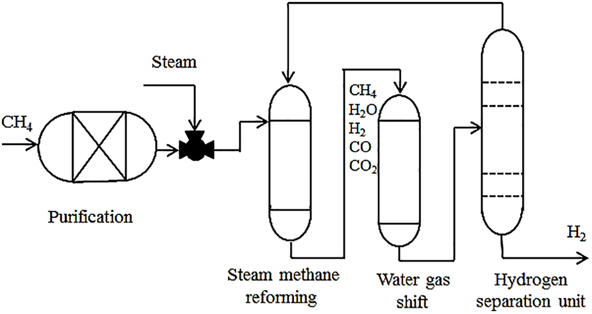
Figure 1: Traditional schematic of the hydrogen production process via steam methane reforming
The chemical reaction of natural gas is characterized by an endothermic reaction. In the reforming process, a dedicated heat source is essential and typically provided by external sources such as boilers, furnaces, or hot waste gas flows. These external heat sources facilitate the conversion of raw materials into hydrogen. As a byproduct, the process generates carbon dioxide, carbon monoxide and non-combustible hydrocarbons. The steam methane reforming (SMR) reaction can be presented as follows:
This reaction involves methane (CH4) reacting with water (H2O) to produce carbon monoxide (CO) and hydrogen gas (H2), which is a key step in the production of hydrogen with the aid of heat and a catalyst. These reactions take place at temperatures between 1073.15 and 1273.15 K and at pressures ranging from 5 to 20 atm. The nickel-based catalysts are widely used for the steam methane reforming (SMR) process due to their high catalytic activity and low cost [30,31].
The conversion of CO to CO2 and H2 occurs through the water (H2O) present in the reforming gases facilitated by a catalyst as described in the following reaction:
The reaction employs two reactors: the high-temperature shift reactor (HTS), operating between 473 and 673 K, and the low-temperature shift reactor (LTS), functioning between 400 and 450 K [32,33]. In the final stage, the reforming stream undergoes purification in the pressure swing absorption (PSA) system, which separates hydrogen from other chemicals by condensing water vapor [34,35]. It’s worth noting that the membrane separation of hydrogen proposed in this study can achieve a high end-of-stream H2 purity, reaching up to 99% [36].
The boil-off gas (BOG) extracted from the tanks is divided into two parts, one for fueling the engines while the other is used for the hydrogen production process, utilizing the complete composition of BOG [37]. Before entering the process, the BOG undergoes heating from 133 to 298 K by the exhaust gases stream (HEX-1). This heated quantity is further split into two portions. The first portion (19) will be directed to the combustion chamber to fulfill the heat requirements for the reforming reaction when needed. The second part undergoes compression (2–3) before entering the reforming process as illustrated in Fig. 2. Before the methane and water are mixed within the reformer, the water is pumped to reach the reforming pressure (4–5) and is heated utilizing the heat generated by the water gas shift reactor (WGS) (5–6). This process involves the employment of the hydrogen produced (HEX-6) (6–7), the reforming gases (HEX-4) (7–8), and the exhaust gases (HEX-3) (8–9).
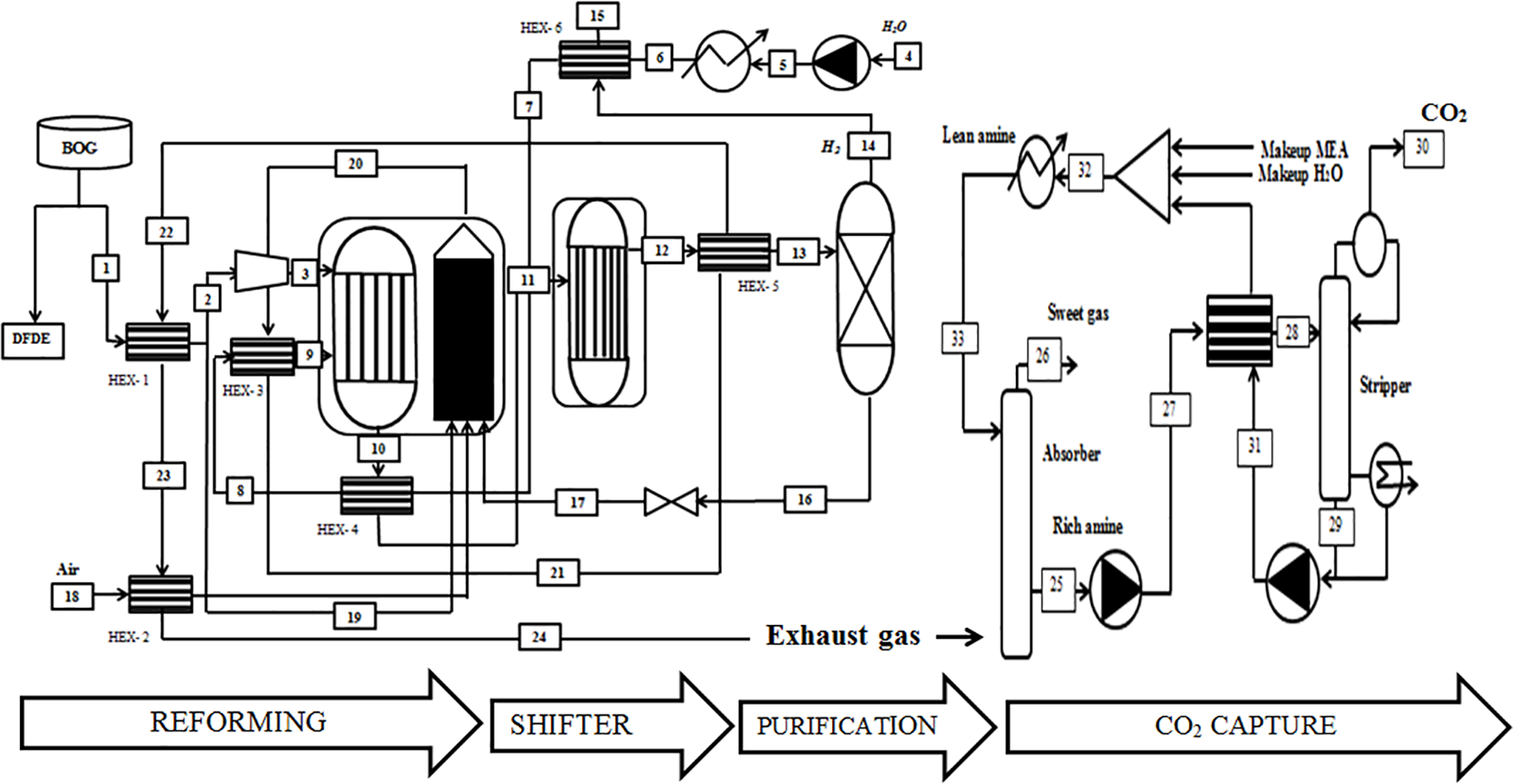
Figure 2: Schematic of the combination of the Steam Methane Reforming (SMR) and the Ship-Based Carbon Capture (SBCC)
The reformer gases experience a temperature decrease to 573 K (the temperature for the water gas shift (WGS) reaction). Upon exiting the WGS, they are reheated by the exhaust gases (HEX-4). Subsequently, the reformer gases undergo expansion to atmospheric pressure (15–16) before being directed to the combustion chamber. The hydrogen’s temperature is then lowered to 346 K after passing through the heat exchanger (HEX-6). Simultaneously, the exhaust gases pass through (HEX-2) to heat the air before entering the combustion chamber. Afterward, they are routed to the absorber (24) to capture CO2 emissions. This integrated process showcases the efficient utilization of heat from various stages in order to optimize the overall system performance.
2.2 Modeling and Simulation of Ship-Based Carbon Capture (SBCC) Process
The extraction of CO2 from exhaust gas streams through aqueous MEA scrubbing stands out as one of the most promising and successful technologies [38]. The MEA solvent boasts favorable characteristics in terms of Health, Safety, and Environment (HSE), including biodegradability, eco-toxicity, and human toxicity. Additionally, the technology is well-established and mature, featuring an easy-to-use solvent with relatively fast kinetics. The solvent’s volatility is generally low, posing no significant issues for onshore carbon capture. Despite these advantages, the MEA solvent does have drawbacks, including a relatively high energy requirement, a low maximum desorption pressure, and susceptibility to high oxidative solvent degradation. However, the elevated energy demand of MEA is not necessarily a liability for Ship-Based Carbon Capture (SBCC). In vessels with ample waste heat from exhaust gases, high capture rates can be achieved, and using a solvent with lower regeneration energy may not offer substantial additional benefits [39].
When the exhaust gas from the SMR process enters the absorber, it undergoes cooling to approximately 313.15 K, as shown in Fig. 2. Within the absorber, the incoming CO2-containing gases interact with a counter-currently flowing amine solvent, initiating a chemical reaction between the absorbent and CO. The amine-rich solvent, now containing absorbed CO2, is then heated to around 377.15 K via the lean/rich cross heat exchanger (HEX-7) and directed to the top of the stripper (28). Within the stripper, the amine solvent undergoes regeneration with the heat supplied to the reboiler using steam. Following condensation, the produced CO2 gas exits the stripper’s overhead with a purity of 98% mole, achieving a capture rate of 90% (30). The lean amine solvent from the stripper is cooled and recycled back to the absorber (33).
The captured CO2 is subsequently compressed and transported for various uses or injected into deep underground rock formations for permanent storage. To resist movement, the absorber and stripper columns in this study were designed with limitations on height and diameter, opting for a low-pressure drop. Packed columns, particularly those with Mellapak 250X structured packing, were chosen as they are more suitable than tray columns for this study [40,41].
Table 1 serves as an accumulator for the data necessary in the present simulation throughout all stages to provide a better understanding of the process.
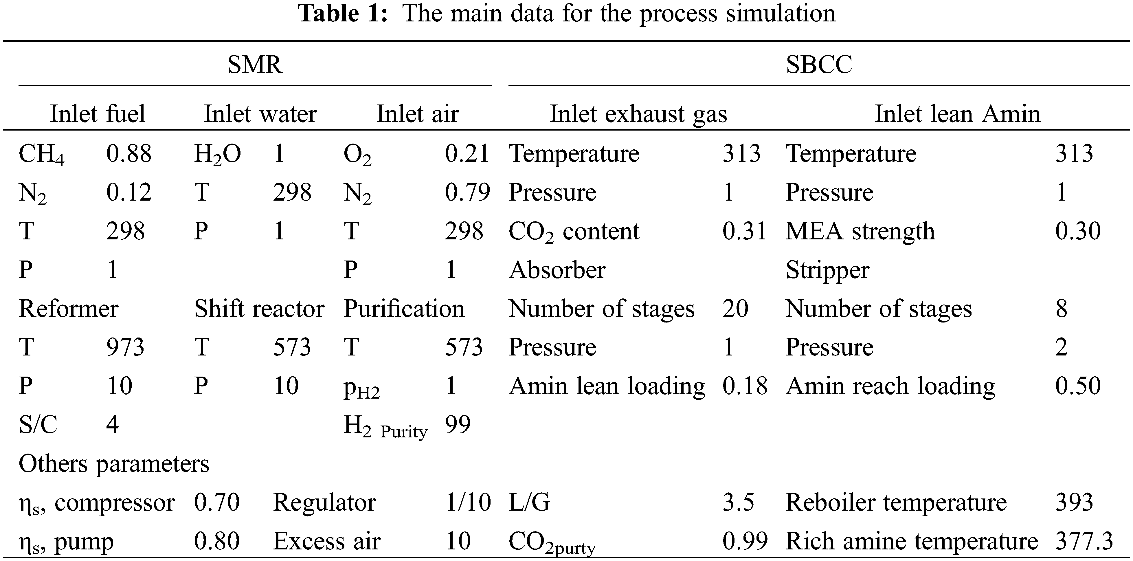
The aforementioned steam methane reforming (SMR) process undergoes modeling through a thermodynamic approach. The program was developed using EES software, permitting various modifications regarding plant parameters such as reforming temperature, air and boil-off gas (BOG) temperature at the combustion chamber inlet, and steam/carbon ratio (S/C). These modifications were made to assess their impact on the plant’s overall performance. The primary goal of this study is to minimize regeneration energy consumption while upholding a high CO2 recovery rate. Several critical design parameters, including CO2 lean loading (the moles of CO2 per mole of MEA in the solvent), temperature profile, and the height along the absorption column, are identified as significant contributors for energy regeneration. Therefore, a sensitivity analysis is conducted to evaluate how CO2 removal and thermal energy consumption are influenced by various key design parameters, encompassing CO2 lean loading and factors affecting temperatures in the absorber.
The reformer’s and the CO2 removal operating parameters are based on the DOE’s demonstration SMR plant in Las Vegas, NV, USA [42,43], along with the previous works [44].
The thermal efficiency and H2 generation are acknowledged as the main parameters of the present process. The ratio of power output to heat input representing the thermal efficiency is viewed as a critical metric regarding the performance overall evaluation [30]. Thermal efficiency is calculated as follows:
The hydrogen yield is defined as the hydrogen-produced moles from the reaction for each mole of methane [45]. Mathematically, it can be represented as follows:
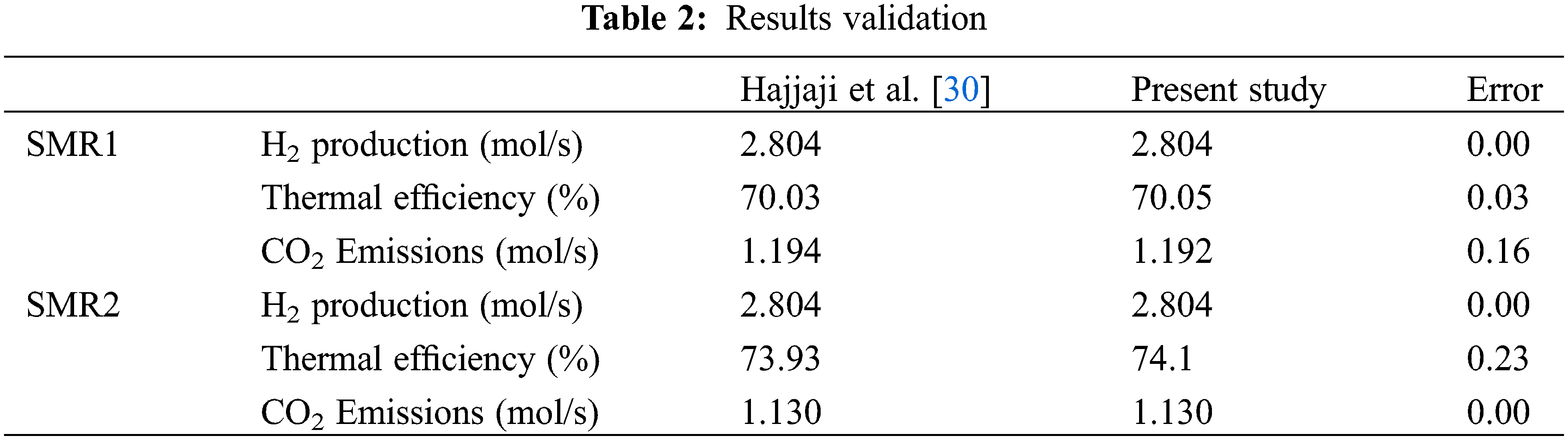
A comparison between the present work’s result and the work published by Hajjaji et al. [30] is presented in Table 2. The slight deviation between the two results is attributed to the difference in the fluid package properties used by both parties.
3.2.1 Effect of Reforming Temperature and (S/C) Ratio Variation
Fig. 3 explains the influence of the reforming temperature on the plant and why as per Chatelier’s principal [46] boosting the latter would implement radical changes concerning both hydrogen production and thermal efficiency.
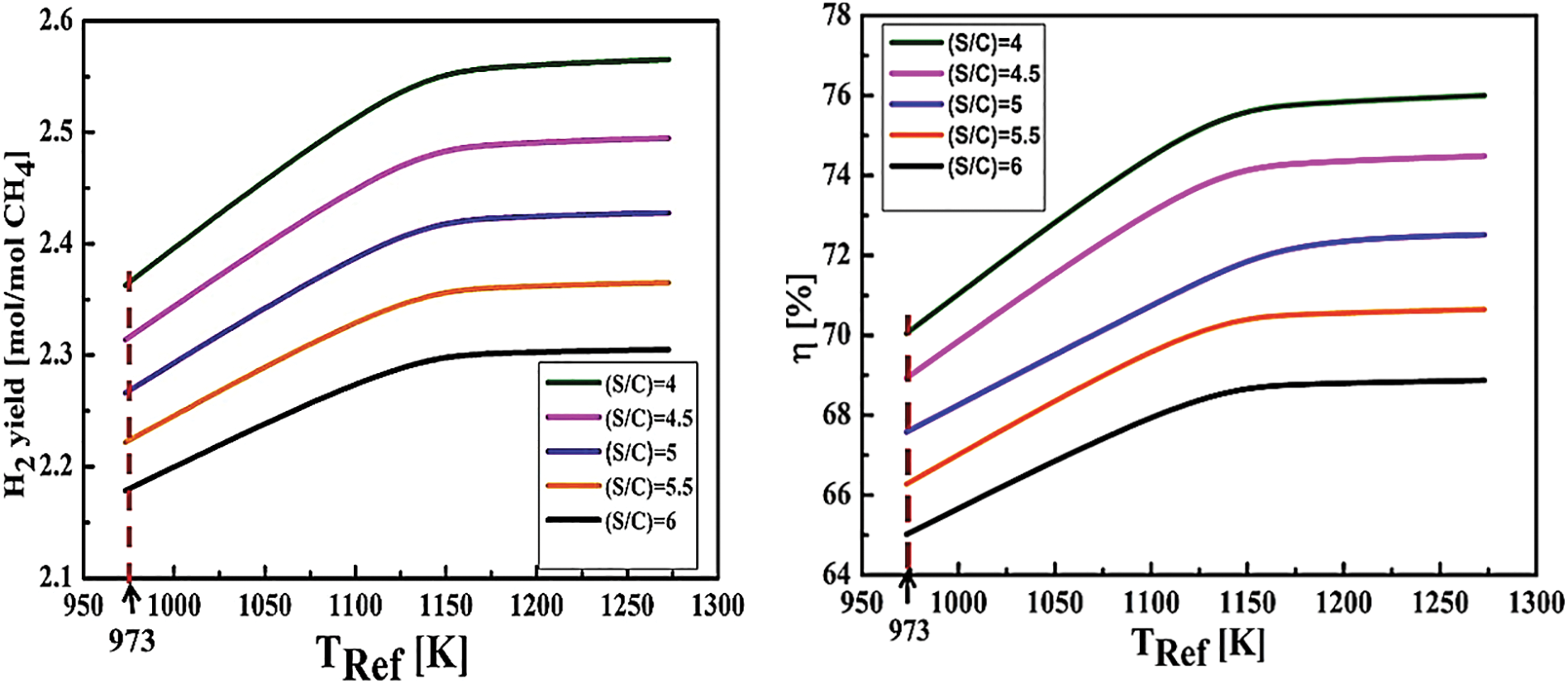
Figure 3: The influence of the reforming temperature and (S/C) ratio on both hydrogen yield and thermal efficiency (TShift = 573 K, Tpurification = 723 K, pref = 10 atm)
After monitoring the reformer’s temperature variations from 950 to 1300 K, the first half (before the inflection point) favors the reformer’s temperature rise to a certain level, creating a proportional increase in hydrogen production. In addition as an effect of the increased heat demand of the reformer, the s/c ratio elevates from 4 to 6, leaving the hydrogen production chain to experience a notable reduction, hence a thermal efficiency drop. Moreover, as the second half shows, after the inflection points which mark the optimal temperatures of the process, the curves are displaying a slower hydrogen production rate, indicating that the yield has become less sensitive to temperature changes. This behavior is related to the kinetics of the chemical reactions within the reformer. At lower temperatures, reforming and shift reactions occur more rapidly, boosting hydrogen production. However, at higher temperatures, secondary reactions or thermal losses can limit efficiency, resulting in a reduced sensitivity to temperature increases.
3.2.2 Effect of Air Temperature Variation
Fig. 4 illustrates the behavior of the required BOG for the combustion process and the thermal efficiency as a function of combustion air’s temperature. As combustion air temperature increases from 300 to 600 K fuel mass decreases and thermal efficiency increases by around 70%–75%, resulting in lower carbon dioxide emissions since the latter is inversely proportional to the fuel mass flow rate, as suggested by Eq. (5).
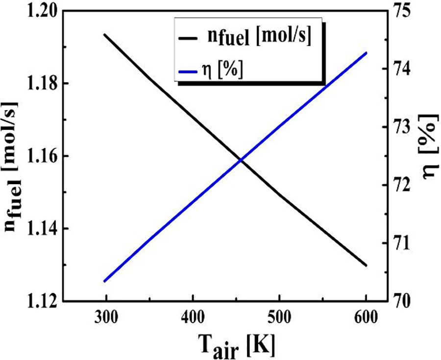
Figure 4: The influence of the air temperature on fuel consumption and thermal efficiency (TShift = 573 K, Tpurification = 723 K, (S/C) ratio = 4, pref = 10 am)
3.2.3 Effect of BOG Temperature Variation
Fig. 5 reflects the sensitivity of thermal efficiency and BOG performance while varying the fuel temperature from 298 to 600 K. Thermal efficiency curve shows a negligible behavior, ranging between 70% and 70.5%, while the required quantity of BOG decreased steadily when increasing fuel temperature.
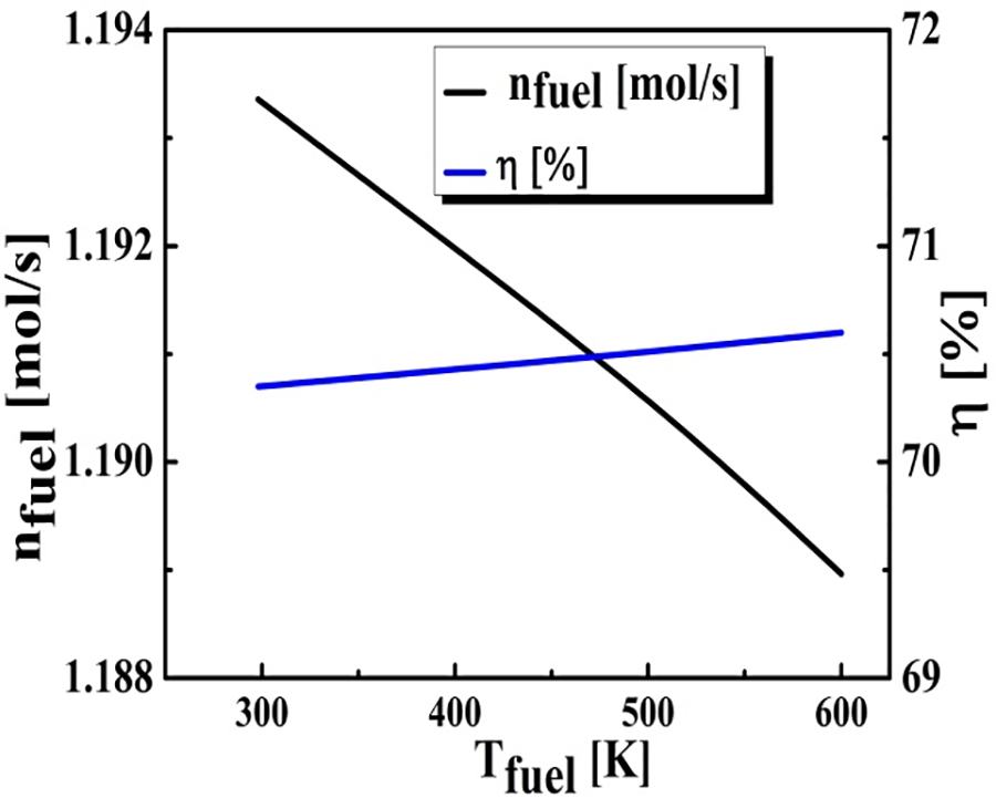
Figure 5: The influence of the BOG temperature on fuel consumption and thermal efficiency (TShift = 573 K, Tpurification = 723 K, (S/C) ratio = 4, pref = 10 am)
3.2.4 Effect of CO2 Lean Loading
Fig. 6 depicts the progression of heat consumption and CO2 removal concerning variations in CO2 lean loading. The data outlines that both CO2 removal and heat consumption values reach their highest at a CO2 lean loading of 0.16 (mol CO2/mol MEA). The curvature’s change in the heat consumption curve reflects variations in the thermal efficiency of the reforming process at different temperatures. Initially, as the reformer temperature increases, heat consumption rises in a near-linear fashion. However, beyond a certain point, the heat consumption increases at an accelerated rate due to the need for additional energy to maintain effective reactions at higher temperatures. This phenomenon is attributed to reactor dynamics, where higher temperatures require more complex heat management to compensate for thermal losses as well as enhance the reaction. Practically, this indicates that excessively high temperatures may not be economically or practically viable due to the increased energy. Moreover, the higher CO2 lean loading goes, the lower heat consumption and CO2 removal curves go, emphasizing the importance of selecting a top-notch CO2 lean loading to aid in maintaining the desirable CO2 removal efficiency levels while minimizing the heat consumption to help refine the overall performance.
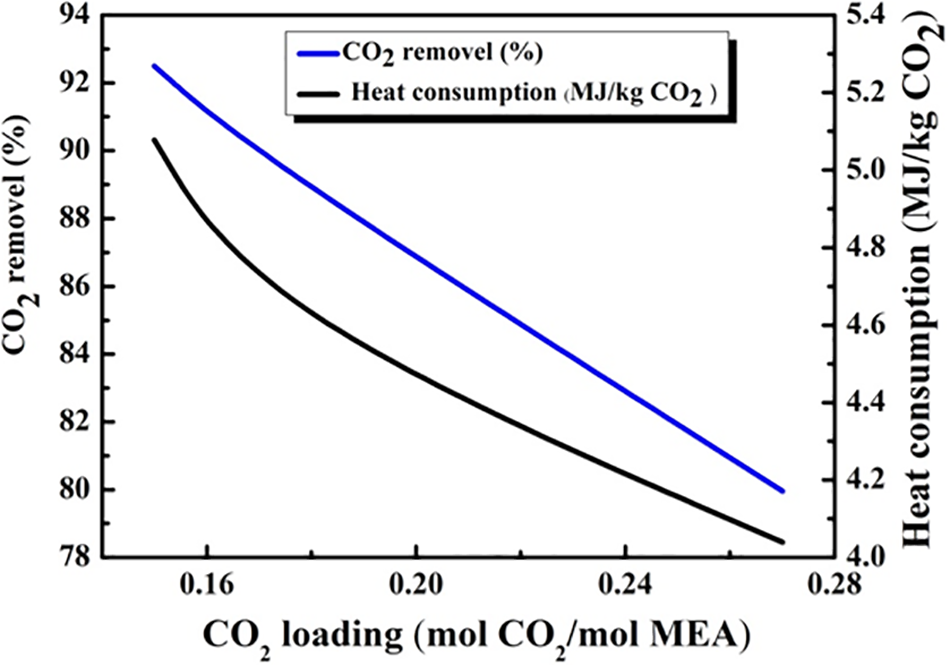
Figure 6: The influence of the CO2 loading (mol CO2/mol MEA)
3.2.5 Effect of the Absorption Temperature
Fig. 7 offers insights into the impact of absorption temperature variations on heat consumption and CO2 removal. When increasing the temperature from 300 to 325 K both curves experience a significant change, increasing the heat consumption while decreasing CO2 removal. The shared interconnection nature between hydrogen production and heat consumption allows the interpretation of the inflection points symmetry in both curves where the trade-offs between hydrogen production and heat consumption are most significant. Higher temperatures are not highly favored as they lead to major energy consumption and reduction in CO2 removal efficiency, which prioritizes the need to properly manage and optimize the absorption temperature in order to maintain a well-balanced energy efficiency and effective CO2 capture relationship.
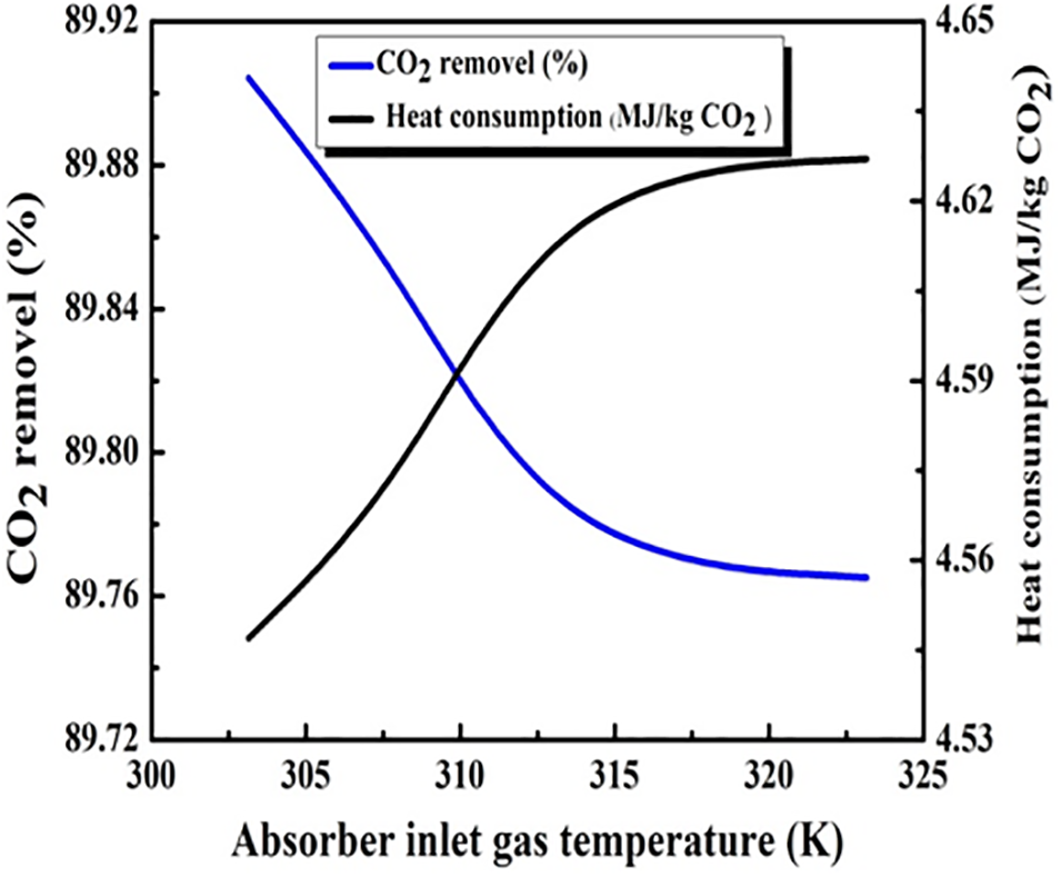
Figure 7: The influence of the absorber inlet gas temperature (K)
3.2.6 Effect of the Number of Absorption Stages
Fig. 8 illustrates the influence of the number of stages on both heat consumption and CO2 capture. Increasing the column stage number from 10 to 20 contributes in a 10% rise in CO2 removal efficiency reaching 90%. In addition, the heat consumption decreases from 9 to 4 MJ/kg CO2. This relationship underscores the positive correlation between the number of stages and the enhancement of CO2 removal efficiency coupled with energy consumption reduction. This process highlights the importance of optimizing the number of stages in order to achieve a desirable balance between CO2 captures effectiveness and the system energy efficiency.
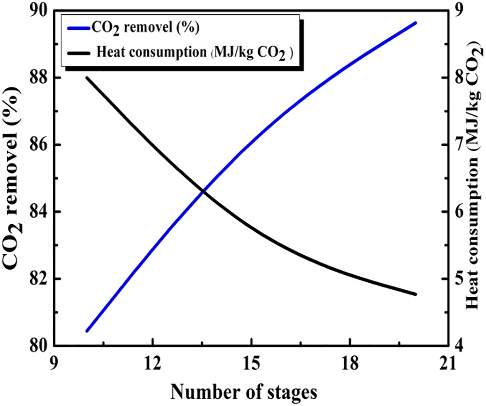
Figure 8: The influence of the number of stages
The present work proposes a thermodynamic model for a hydrogen production plant with the integration of a carbon capture process (SBCC) on board Algerian liquefied natural gas (LNG) carrier. Hydrogen is produced via the methane reforming process (SMR), where the feedstock is provided by the excess flue gas (BOG) generated in the liquefied natural gas tanks, preventing the disposal of the latter in the gas combustion unit (GCU) with no further use. This technology is viewed as an attractive proposition, both technical and economically wise, for the maritime sector to reach zero net emissions and limit global warming at 1.5°C. The key findings from this study can be summarized as follows:
In order to improve the plant performance, variations of the reforming, combustion air and BOG temperature, as well as the steam/carbon ratio (S/C), are assessed for the steam methane reforming (SMR). In addition, for the ship-based carbon capture (SBCC), the absorption column height and temperature and lean CO2 loading have been studied.
• In the case of the steam methane reforming process, increasing the temperature of the reformer enhances hydrogen productivity, which improves the plant’s thermal efficiency. In contrast, increasing the steam-to-carbon (S/C) ratio reduces hydrogen productivity and, consequently, the thermal efficiency. Additionally, preheating air before entering the combustion chamber boosts plant efficiency from 70% to 74%. Furthermore, slightly preheating the BOG increases plant efficiency from 70% to 70.6%.
• For the ship-based carbon capture (SBCC) process, research indicates that achieving a CO2 capture rate of 90% necessitates maintaining the absorption column at a temperature of 313 K and column height of 20. Under these conditions, the estimated energy consumption is approximately 4.3 MW per kilogram of CO2 captured.
Acknowledgement: The authors would like to to express profound gratitude towards “PHC TASSILI Project” for their huge support.
Funding Statement: The authors received no specific funding for this study.
Author Contributions: The authors confirm contribution to the paper as follows: study conception and design: Ikram Belmehdi, Boumedian Beladjin; data collection: Mouhamed Djarmouni; analysis and interpretation of results: Ikram Belmehdi, Amina Sabeur, Mohammed El Ganaoui; draft manuscript preparation: Ikram Belmehdi, Amina Sabeur. All authors reviewed the results and approved the final version of the manuscript.
Availability of Data and Materials: The datasets generated during the current study are not publicly available due to information protection policy denying access to unauthorized parties, but are available from the corresponding author on reasonable request.
Ethics Approval: Not applicable.
Conflicts of Interest: The authors declare no conflicts of interest to report regarding the present study.
References
1. United States Environmental Protection Agency. Sources of greenhouse gas emissions: overview; 2021. Available from: https://www.epa.gov/ghgemissions/sources-greenhouse-gas-emissions/U.S.EnvironmentalProtectionAgency. [Accessed 2024]. [Google Scholar]
2. The-Paris-Agreement. The Paris Agreement 2021 study; 2021. Available from: https://unfccc.int/process-and-meetings/the-paris-agreement. [Accessed 2024]. [Google Scholar]
3. Smith T, Jalkanen J, Anderson B, Corbett J, Faber J, Hanayama S, et al. Third IMO GHG study. 2014. London, UK. Available from: https://wwwcdn.imo.org/localresources/en/OurWork/Environment/Documents/Third%20Greenhouse%20Gas%20Study/GHG3%20Executive%20Summary.pdf. [Accessed 2024]. [Google Scholar]
4. European Commission. Regulation of the European parliament and of the council on the use of renewable and low-carbon fuels in maritime transport and amending directive 2009/16/EC (COM (2021) 562 final 2021/0210 (COD) proposal). Brussels; 2021. Available from: https://www.actuenvironnement.com/media/pdf/news-37896-Proposition-Commission-carburants-maritimes. [Accessed 2024]. [Google Scholar]
5. Department for Transport. COP26: clydebank declaration for green shipping corridors; 2021. Available from: https://climate.ec.europa.eu/eu-action/eu-emissions-trading-system-eu-ets_en. [Accessed 2023]. [Google Scholar]
6. The EU Emissions Trading System (EU ETS). July 2015. Available from: https://climate.ec.europa.eu/document/download/5dee0b48-a38f-4d10-bf1a-14d0c1d6febd_en?filename=factsheet_ets_en.pdf. [Accessed 2023]. [Google Scholar]
7. Buhaug Ø, Corbett J, Endresen Ø, Eyring V, Faber J, Hanayama S, et al. Second IMO GHG study 2009 report. In: International Maritime Organization (IMO), 2009; London, UK. Available from: https://wwwcdn.imo.or. [Accessed 2024]. [Google Scholar]
8. Capros P, De Vita A, Tasios N, Papadopoulos D, Siskos P, Zampara M, et al. EU energy, transport and GHG emissions: trends to 2050, reference scenario 2013; 2013. Available from: https://op.europa.eu. [Google Scholar]
9. Long NVD, Lee DY, Kwag CY, Lee YM, Lee SM, Hessel V, et al. Improvement of marine carbon capture onboard diesel fueled ships. Chem Eng Process-Process Intensif. 2021;168:108535. doi:10.1016/j.cep.2021.108535. [Google Scholar] [CrossRef]
10. World Health Organization. Health, environment and climate change: ambient (outdoor) airpollution; 2022. Available from: https://who.int/news-room/fact-sheets/detail/ambient-(outdoor)-air-quality-and-health. [Accessed 2024]. [Google Scholar]
11. Smolinski A, Howaniec N, Ga sior R, Polanski J, Magdziarczyk M. Hydrogen rich gas production through co-gasification of low rank coal, flotation concentrates and municipal refuse derived fuel. Energy. 2021;235:121348. doi:10.1016/j.energy.2021.121348. [Google Scholar] [CrossRef]
12. Heidari M, Tahmasebpoor M, Antzaras A, Lemonidou A. CO2 capture and fluidity performance of CaO-based sorbents: effect of Zr, Al and Ce additives in tri-, bi- and mono-metallic configurations. Process Saf Environ Prot. 2020;144:349–65. doi:10.1016/j.psep.2020.07.041. [Google Scholar] [CrossRef]
13. Gizem SM, Turan HA. Advancements and current technologies on hydrogen fuel cell applications for marine vehicles. Int J Hydrogen Energy. 2022;47(45):19865–75. doi:10.1016/j.ijhydene.2021.12.251. [Google Scholar] [CrossRef]
14. Jianga DB, Longb Y, Fub P, Guob C, Tangb Y, Huang H. A novel multi-stack fuel cell hybrid system energy management strategy for improving the fuel cell durability of the hydrogen electric multiple units. Int J Green Energy. 2023;21:1766–75. doi:10.1080/15435075.2023.2266724. [Google Scholar] [CrossRef]
15. Gu G. Mathematical modeling of membrane CO2 capture for blue hydrogen production. In: International Federation of Automatic Control Conference, 2022; Gwangju, Republic of Korea; p. 304–9. [Google Scholar]
16. Bianco E, Blanco H. Green hydrogen: a guide to policy making. Abu Dhabi: The International Renewable Energy Agency (IRENA); 2020. Available from: https://www.irena.org/publications. [Accessed 2024]. [Google Scholar]
17. Younas M, Sumeer S, Ainy H, Javed F, Fahad R. An overview of hydrogen production: current status, potential, and challenges. Fuel. 2022;316:123317. doi:10.1016/j.fuel.2022.123317. [Google Scholar] [CrossRef]
18. Collodi G. Hydrogen production via steam reforming with CO2 capture. In: 4th International Conference on Safety & Environment in Process Industry, 2010; Milan, Italy; p. 37–42. doi:10.3303/CET1019007. [Google Scholar] [CrossRef]
19. Cho HH, Strezov V, Evans TJ. Environmental impact assessment of hydrogen production via steam methane reforming based on emissions data. Energy Rep. 2022;8:13585–95. doi:10.1016/j.egyr.2022.10.053. [Google Scholar] [CrossRef]
20. Katebah M, Al-Rawashdeh M, Linke P. Analysis of hydrogen production costs in steam-methane reforming considering integration with electrolysis and CO2 capture. Cleaner Eng Technol. 2022;10:100552. doi:10.1016/j.clet.2022.100552. [Google Scholar] [CrossRef]
21. Pruvost F, Cloete S, Pozo CZD, Zaabout A. Blue, green, and turquoise pathways for minimizing hydrogen production costs from steam methane reforming with CO2 capture. Energy Convers Manage. 2022;274:11645820. doi:10.1016/j.enconman.2022.116458. [Google Scholar] [CrossRef]
22. Feenstra M, Monteiro JGMS, Akker JT, Abu-Zahra MR, Goetheer E. Ship-based carbon capture onboard of diesel or LNG-fuelled ships. Int J Greenhouse Gas Control. 2019;85:1–10. doi:10.1016/j.ijggc.2019.03.008. [Google Scholar] [CrossRef]
23. Einbu A, Pettersen T, Morud J, Tobiesen A, Jayarathna C, Skagestad R, et al. Onboard CO2 capture from ship engines. In: 15th International Conference on Greenhouse Gas Control Technologies, 2021. doi: 10.2139/ssrn.3821141. [Google Scholar] [CrossRef]
24. Lee S, Yoo S, Park H, Ahn J, Chang D. Novel methodology for EEDI calculation considering onboard carbon capture and storage system. Int J Greenhouse Gas Control. 2020;105:103241. doi:10.1016/j.ijggc.2020.103241. [Google Scholar] [CrossRef]
25. Jasper AR, Eirini S, Vincent D, Joan T, Van DA, Linders MJG, et al. Advancements in ship-based carbon capture technology on board of LNG-fuelled ship. Int J Greenhouse Gas Control. 2022;114:103575. doi:10.1016/j.ijggc.2021.103575. [Google Scholar] [CrossRef]
26. Aspen hysys physical property methods and models, software version. Safir: Societe Algerienne d’Ingenierie et de Realisation; 2019. Available from: https://www.pagesjaunes-dz.com/Companies/detail/80991b18f5852058f23762701b0d62fc/safir-societe-algerienne-d-ingenierie-de-realisation. [Accessed 2024]. [Google Scholar]
27. Dobrota Đ, Lalić B, Komar I. Problem of Boil-off in LNG supply chain. Trans Marit Sci. 2013;2(2):91–100. doi:10.7225/toms.v02.n02.001. [Google Scholar] [CrossRef]
28. Romero Gómez J, Romero Gómez M, Bernal JL, Baaliña Insua JA. Analysis and efficiency enhancement of a boil-off gas reliquefaction system with cascade cycle on board LNG carriers. Energy Convers Manage. 2015;94:261–74. doi:10.1016/j.enconman.2015.01.074. [Google Scholar] [CrossRef]
29. Ghasem N. A review of the CFD modeling of hydrogen production in catalytic steam reforming reactors. Int J Mol Sci. 2022;23:16064. doi:10.3390/ijms232416064. [Google Scholar] [PubMed] [CrossRef]
30. Hajjaji N, Pons MN, Ammar H, Renaudin V. Exergy analysis: an efficient tool for understanding and improving hydrogen production via the steam methane reforming process. Energy Policy. 2012;42:392–9. doi:10.1016/j.enpol.2011.12.003. [Google Scholar] [CrossRef]
31. Minkkinen A, Giroudiere F, Colin J. Gas to hydrogen power process. In: 16th World Hydrogen Energy Conference, 2006; WHEC; Lyon, France. [Google Scholar]
32. Warmuziński K, Tańczyk M. Multicomponent pressure swing adsorption. Part I modeling of a large-scale PSA installation. Chem Eng Process Process Intensif. 1997;36(2):89–99. doi:10.1016/S0255-2701(96)04164-5. [Google Scholar] [CrossRef]
33. Voss C. Applications of pressure swing adsorption technology. Adsorption. 2005;11(1):527–9. doi:10.1007/s10450-005-5979-3. [Google Scholar] [CrossRef]
34. Ribeiro AM, Grande CA, Lopas LFG, Loureiro JM, Rodrigues AE. A parametric study of layered bed PSA for hydrogen purification. Chem Eng Sci. 2008;63(21):5258–73. doi:10.1016/j.ces.2008.07.017. [Google Scholar] [CrossRef]
35. Majlan EH, Daud WRW, Iyuke SE, Abu Bakar M, Kadhum AAH, Takriff MS, et al. Hydrogen purification using compact pressure swing adsorption system for fuel cell. Int J Hydrogen Energy. 2008;63(21):5258–73. doi:10.1016/j.ijhydene.2008.12.093. [Google Scholar] [CrossRef]
36. Adhika S, Fernando S. Hydrogen membrane separation techniques. Ind Eng Chem Res. 2006;45(3):875–81. doi:10.1021/ie050644l. [Google Scholar] [CrossRef]
37. Querol E, Gonzalez-Regueral B, García-Torrent J, García-Martínez MJ. Boil off gas (BOG) management in Spanish liquid natural gas (LNG) terminals. Appl Energy. 2010;87(11):3384–92. doi:10.1016/j.apenergy.2010.04.021. [Google Scholar] [CrossRef]
38. Moser P, Schmidt S, Sieder G, Garcia H, Stoffregen T. Performance of MEA in a long-term test at the post-combustion capture pilot plant in Niederaussem. Int J Greenhouse Gas Control. 2011;5(4):620–7. doi:10.1016/j.ijggc.2011.05.011. [Google Scholar] [CrossRef]
39. Idem R, Supap T, Shi H, Gelowitz D, Ball M. Practical experience in post-combustion CO2 capture using reactive solvents in large pilot and demonstration plants. Int J Greenhouse Gas Control. 2015;40:6–25. doi:10.1016/j.ijggc.2015.06.005. [Google Scholar] [CrossRef]
40. Lee S, Van Duc Long N, Lee M. Design and optimization of natural gas liquefaction and recovery processes for offshore floating liquefied natural gas plants. Ind Eng Chem Res. 2012;51(30):10021–30. doi:10.1021/ie2029283. [Google Scholar] [CrossRef]
41. Long NVD, Lee M. Advances in distillation retroft. 1st edNew York: Springer; 2017. [Google Scholar]
42. Lutz AE. IV.C.2 power parks system simulation. DOE Hydrogen Program. Progress Report; 2004. Available from: https://www.hydrogen.energy.gov/library/annualprogress/annual_progress04. [Accessed 2024]. [Google Scholar]
43. Simpson AP, Lutz AE. Exergy analysis of hydrogen production via steam methane reforming. Int J Hydrogen Energy. 2007;32(18):4811–20. doi:10.1016/j.ijhydene.2007.08.025. [Google Scholar] [CrossRef]
44. Øi LE. Aspen HYSYS simulation of CO2 removal by amine absorption from a gas based power plant. In: SIMS2007 Conference, Oct 30–31, 2007; Gøteborg, Sweden; p. 73–81. Available from: www.researchgate.net/publication/228402007_Aspen_HYSYS_simulation_of_CO2_removalby_amine_absorption_from_a_gas_based_power_plant. [Accessed 2024]. [Google Scholar]
45. Chen WH, Lin MR, Lu JJ, Chao Y, Leu TS. Thermodynamic analysis of hydrogen production from methane via autothermal reforming and partial oxidation followed by water gas shift reaction. Int J Hydrogen Energy. 2010;35:11787–97. doi:10.1016/j.ijhydene. [Google Scholar] [CrossRef]
46. Miguel P. Understanding Le Châtelier’s principle fundamentals: five key questions. Chem Teacher Int. 2021;4(3):203–5. doi:10.1515/cti-2020-0030. [Google Scholar] [CrossRef]
Cite This Article
 Copyright © 2025 The Author(s). Published by Tech Science Press.
This work is licensed under a Creative Commons Attribution 4.0 International License , which permits unrestricted use, distribution, and reproduction in any medium, provided the original work is properly cited.
 Downloads
 Citation Tools