
 Submit a Paper
 Propose a Special lssue
 Open Access
ARTICLE

Influence of Nozzle Geometry and Operating Parameters on High-Pressure Water Jets
1 School of Thermal Engineering, Shandong Jianzhu University, Jinan, 250101, China
2 Shanxi Fusheng Aluminium Co., Ltd., Yuncheng, 044399, China
3 Zhejiang JingLiFang Digital Technology Group Co., Ltd, Hangzhou, 310013, China
* Corresponding Authors: Chao Zhang. Email: ; Yongxing Song. Email:
Fluid Dynamics & Materials Processing 2025, 21(11), 2761-2777. https://doi.org/10.32604/fdmp.2025.072236
Received 22 August 2025; Accepted 06 November 2025; Issue published 01 December 2025
 View Full Text
 Download PDF
Abstract
High-pressure water jet technology has emerged as a highly effective method for removing industrial-scale deposits from pipelines, offering a clean, efficient, and environmentally sustainable alternative to conventional mechanical or chemical cleaning techniques. Among the many parameters influencing its performance, the geometry of the nozzle plays a decisive role in governing jet coherence, impact pressure distribution, and overall cleaning efficiency. In this study, a comprehensive numerical and experimental investigation is conducted to elucidate the influence of nozzle geometry on the behavior of high-pressure water jets. Using Computational Fluid Dynamics (CFD) simulations based on the Volume of Fluid (VOF) approach, the jet dynamics and impingement characteristics of three representative nozzle configurations—flat, conical, and tapered—are systematically analyzed. Particular attention is devoted to the tapered nozzle, where variations in the outlet diameter are explored to determine their effect on flow structure, jet stability, and impact performance. The numerical predictions are rigorously validated against experimental measurements, demonstrating excellent quantitative agreement and confirming the robustness of the computational model. Results show that the tapered nozzle, characterized by its elongated conical transition section, promotes a more stable jet core and superior efflux performance compared to flat and conical geometries. Furthermore, the exit diameter is found to exert a profound influence on jet development. At an inlet pressure of 130 MPa, increasing the tapered nozzle’s outlet diameter from 0.8 mm to 1.2 mm enlarges the coherent core region, enhances jet stability, and improves hydraulic energy utilization. Under these conditions, the total impact pressure on the target surface increases by 33.14%, while the overall cleaning efficiency improves by 40.44%.Keywords
Prolonged operation of the alumina digestion line in the Bayer Process results in tenacious scale formation on the pipe walls [1]. This scaling, which occurs under high-temperature and high-pressure conditions, can reduce heat transfer efficiency by 20–50%, which in turn increases energy consumption and maintenance costs, while also posing serious safety risks [2]. Localized overheating due to fouling can produce thermal stress cracks, increasing the risk of pipeline rupture and media leakage. The scale layers can cause localized overheating, potentially leading to thermal stress cracking and subsequent tube rupture with media leakage [3,4]. Furthermore, scale accumulation increases the system operating pressure, creating the risk of equipment overpressure incidents. Conventional chemical cleaning methods present additional environmental concerns due to the generation of toxic wastewater, while traditional physical cleaning often fails to meet the required efficiency standards.
High-pressure water jet cleaning technology is an advanced solution to these challenges, offering superior cleaning efficiency, operational safety, and environmental compatibility. To investigate the influence of different nozzle structures on material removal performance, two kinds of electro-optic-liquid coupling nozzles were studied. Single-jet and multi-jet focusing structures are proposed through simulation and experimentation [5]. The structural characteristics of nozzles critically determine the fluid dynamic behavior, which directly governs both cleaning performance and operational safety [6]. This study aims to improve cleaning performance while mitigating the environmental and operational safety limitations characteristic of both chemical and physical cleaning.
The effects of nozzle distance and impact angle variations on the impact pressure of water jets acting on the tank surface were investigated using multiphase flow dynamics simulations. It was concluded that higher nozzle inlet pressures were required to clean the tank wall when the nozzle distance and impact angle were increased [7]. Furthermore, three-dimensional particle tracking of nozzle jet processes was performed to investigate how turbulent attenuation varies with jet velocity, nozzle size, and nozzle spacing [8].
Advances in erosion and nozzle research have leveraged simulations to examine inlet pressure effects on gas-solid nozzles, revealing key characteristics of the flow field, impact velocity, and jet behavior [9]. The distribution and propagation of pressure waves within the jet were studied. Generate shock waves that alter the geometry, trajectory, and conditions of the jet, introducing additional instabilities and complexities. The JEBEA experimental facility was utilized, over-expanded and under-expanded discharges were conducted through nozzles with inner diameters ranging from 2 to 6 mm. High-speed camera direct observation and image processing were employed to analyze jet dynamics [10].
The study of nozzle wear also provides valuable insights for improving nozzle efficiency and extending service life. Nozzle wear was studied using a CFD-DEM coupled simulation, which showed that the particle kinetic energy exhibited minimal dependence on particle count or inlet velocity [11]. Additionally, hydrodynamic analysis identified an optimal nozzle-to-target distance and impact angle, maximizing the wall shear stress and enhancing practical performance [12].
The influence of jet parameters on coal fragmentation was investigated through combined experiments and simulations, with a quantitative analysis of the water jet, offering valuable insights for long-range nozzle design optimization [13]. Moreover, CFD was used to examine the turbulent two-phase flow distribution in different nozzle types, elucidating the relationships between nozzle geometry, flow phenomena, and wall shear stress [14].
Significant advancements have been made in the development of non-contact cleaning systems, particularly those that employ high-pressure nozzles. CFD with ANSYS software (2023R1) enabled the optimization of jet parameters (velocity and coverage) in a developed system, increasing the cleaning efficiency [15]. A novel flow mapping technique was introduced to characterize the nozzle jet and validated against planar laser-induced fluorescence data with good agreement [16]. Additionally, the slender jet equation was derived using a physics-based approach and validated against predictions from a full three-dimensional axisymmetric (3DA) algorithm [17]. In a different approach, gas and water jets were combined to assist laser slotting while examining the effects of variations in the nozzle exit diameter on the jet characteristics [18]. Furthermore, nozzle parameter optimization was performed using both ALE simulations and experimental tests, with a particular focus on the effects of the cone angle, diameter, and length on soil impact characteristics [19].
In the low-pressure section, much of the research relies on numerical simulations and bench testing. In contrast, studies in the high-pressure section predominantly employ numerical simulation methods, with actual tests or field applications being relatively scarce [20,21,22]. This study verifies the jet characteristics of different nozzle types through numerical simulations and experiments. The aim of this study is to propose a nozzle selection method for actual industrial cleaning scenarios, with a focus on improving process safety and environmental sustainability in industrial cleaning applications. An efficient nozzle structure not only improves cleaning efficiency but also reduces the operational risks associated with high-pressure water jet systems, such as energy overconsumption and equipment fatigue. The simulation results are consistent with the experimental results, effectively ensuring the safety and economy of the cleaning process. This study provides practical guidance for actual cleaning operations.
Through the literature study and inverse analysis of the physical structure, the core geometric characteristic parameters of the nozzle are determined. Three different nozzle models are proposed in this study: flat, conical and tapered, as shown in Fig. 1. The structural parameters of the nozzles are shown in Fig. 2 and include key dimensions such as the inlet diameter (D), taper angle (α), length of the tapered section (L), length of the flat section (l), and outlet diameter (d) [23]. The primary target for high-pressure water jet cleaning is the heat exchanger used in the alumina steamer tube. According to the high-pressure water jet cleaning unit flow rate of 150 L/min and working pressure of 130 MPa, the internal structure of the nozzle parameters is slightly adjusted. The nozzle parameters are summarized in Table 1.
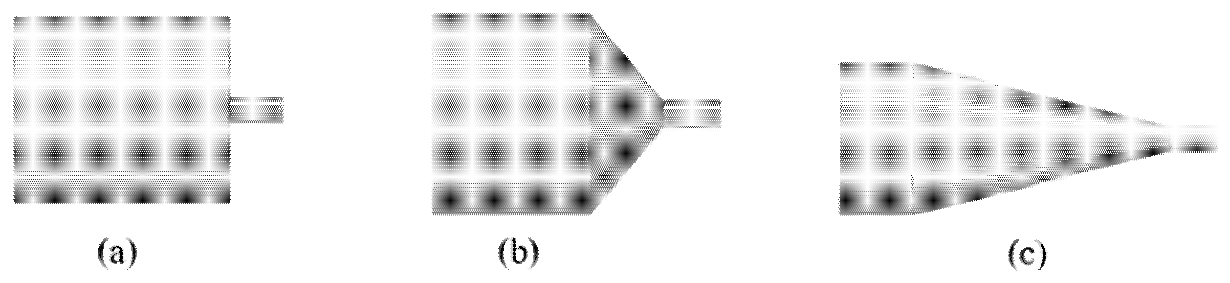
Figure 1: High-pressure nozzle model. (a) Flat type; (b) Conical straight type; (c) Tapered type.
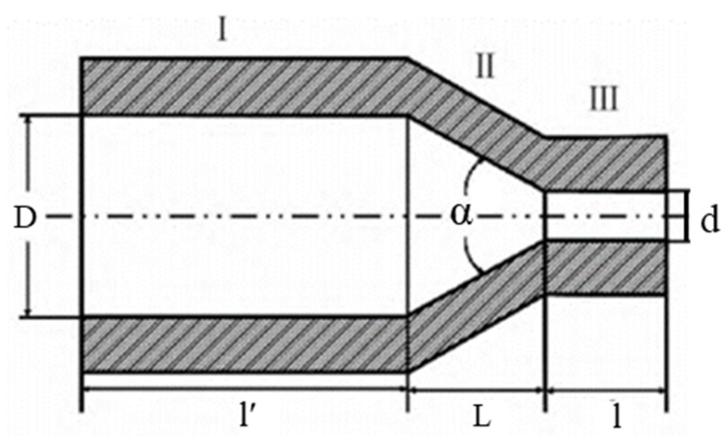
Figure 2: Nozzle structure parameter diagram.
Table 1: Nozzle model parameter size table.
| Nozzle Type | Inlet Diameter D (mm) | Tapering Angle α (°) | Tapered Section Length L (mm) | Length of Flat Section l (mm) | Outlet Diameter d (mm) |
|---|---|---|---|---|---|
| Flat type | 7 | 0 | 0 | 2 | 1 |
| Conical straight type | 7 | 100 | 2.5 | 2 | 1 |
| Tapered type | 7 | 28 | 10.5 | 2 | 1 |
As shown in Fig. 3, the structure of the nozzle water jet is divided into three sections: the initial, basic and dissipation sections [24]. In the initial region of the jet, high energy concentration and high flow velocity are exhibited. In the basic region, the water jet maintains its structural integrity, generating strong impact and cutting forces that enable effective surface cleaning. Although the energy in this region is lower than that in the initial region, it is maintained at a level that avoids potential damage to the cleaned surface. In the dissipative region, the adhesive force, kinetic pressure, turbulent kinetic energy, and axial velocity of water jet gradually decrease, leading to a reduction in cleaning effectiveness. Therefore, to achieve the best cleaning results, it is crucial to locate the target surface within the basic cross-section where the jet can exert the most effective cleaning force.
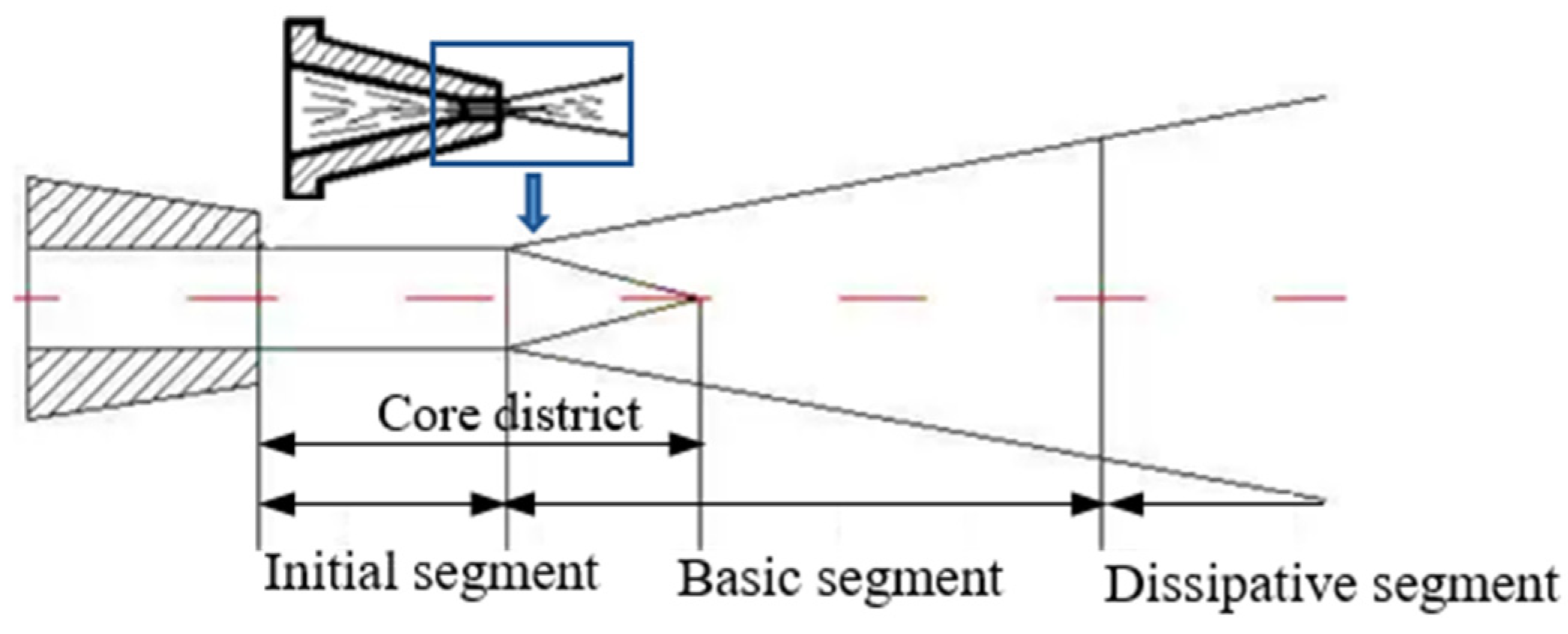
Figure 3: Nozzle water jet structure.
To reduce the dispersion of the jet in the propagation process, the plant cleaning conditions and unit cleaning parameters are adjusted. The cleaning target distance is set to 15 mm. For the selection of the impact angle, a reasonable angle increases the contact area between the water jet and the target surface while minimizing damage to the pipe wall, thereby enhancing the cleaning effectiveness. After multiple cleaning trials, the impact angle is preliminarily set to 75°. (The subsequent impact angle should be adjusted based on the actual conditions. Multiple factors influence the angle, including: unit parameters, raw material conditions, and pipeline grade). The corresponding fluid domain model is illustrated in Fig. 4.
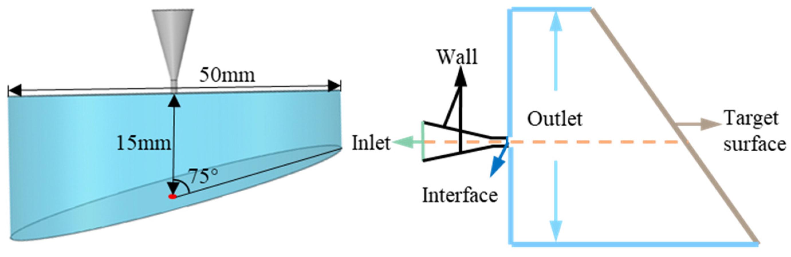
Figure 4: Boundary conditions and dimensions of the fluid domain.
The interaction of the jet with the surrounding air results in inherently complex properties of the nozzle jet flow field. Water jets entering the air are a typical example of multiphase flow. Three numerical models are commonly used to simulate multiphase flows: the VOF model, the Mixture model, and the Eulerian model, which can accurately describe the interphase interactions and is suitable for simulating complex flow phenomena, such as the movement of bubble columns and the uplift of particles [25,26]. Based on the flow characteristics of this study, the VOF model, which has a strong ability to capture interfaces, is chosen for the calculation and analysis after a comprehensive comparison. The mathematical control equations are as follows.
- (1)Volume Fraction Transport Equation
- (2)Continuity Equation
The fluid is incompressible and there is no mass exchange between air and water.
- (3)Momentum Equation
To better characterize the multiphase flow behavior of ultra-high pressure jet, a transient simulation based on the PISO algorithm is implemented. Owing to the presence of high pressure gradients and strong body forces, the PRESTO scheme is employed for the spatial discretization of the pressure term. Unlike standard schemes, which assume a linear variation of pressure across cells, it enables more accurate calculation of the pressure field under ultra-high pressure conditions. To balance computational stability and accuracy, the turbulent kinetic energy and turbulent dissipation rate are discretized with a first-order upwind scheme, whereas a second-order upwind scheme is applied to the momentum equations for higher resolution [27]. The specific simulation parameters are listed in Table 2.
Table 2: Basic parameter Settings.
| Analog Parameters | Plan |
|---|---|
| Multiphase flow model | Volume of Fluid |
| Turbulence model | Standard κ-ε model |
| Pressure inlet (MPa) | 130 |
| Gauge Pressure outlet (Pa) | 0 |
| Wall | No-Slip-Condition |
| Principal phase | Air |
| Secondary phase | Water-liquid |
| Inlet secondary phase volume fraction (%) | 1 |
| Outlet secondary phase reflux volume fraction (%) | 0 |
Tapered and straight cross-section nozzles with small dimensions and significant changes in velocity gradients are subjected to local mesh refinement in these two regions to ensure the accuracy of the calculation results [19,28]. Hexahedral meshes are used in the simulations, as shown in Fig. 5a, which provide flexibility in dealing with complex geometries while maintaining computational efficiency.
Figure 5: Grid model and Grid independence verification (a) Grid division; (b) Grid independence verification.
A grid independence study is conducted to ensure the robustness and accuracy of the numerical results. The grid density is systematically varied to determine the effect of grid refinement on the simulation results [5]. As shown in Fig. 5b, the total pressure value at the monitoring point at the center of the tracked target surface is tracked with a gradual increase in the grid density. A comparison of the results at different grid densities reveals that the physical quantities at the monitoring point gradually stabilize as the grid resolution increases, indicating that the effect of further refinement on the results is not significant. A mesh volume of 2.21 million is selected for the simulation, and the minimum mesh size is 0.08 mm.
3 Simulation Results and Analysis
3.1 Effect of Nozzle Structure on Jet Characteristics
Jet velocity is crucial for evaluating jet system performance, as it affects the momentum transfer, impact force, and flow characteristics. Fig. 6a–c illustrates the velocity distributions of the three nozzles. The velocity gradient is most pronounced in the converging and straight sections of the nozzle, which are characterized by a sharp increase in velocity and an enhanced dynamic response of the jet. The X-axis is defined along the direction of the jet in the nozzle. The velocity variation trends of various nozzle types along the jet direction are analyzed, and Fig. 7 is obtained. The peak velocity at the exit of the three nozzles is approximately 511.81 m/s. However, distinct decay patterns emerge downstream owing to differences in the internal geometry and resulting flow mechanisms.
Figure 6: Velocity distribution clouds in the fluid domain of different nozzle types. (a) Flat type; (b) Conical straight type; (c) Tapered type.
Figure 7: The variation curves of jet velocity along the air domain axis of different types of nozzles.
The conical straight nozzle exhibits a short-range velocity increase immediately after ejection, which is attributable to flow redevelopment and internal pressure recovery [7]. Subsequently, the jet undergoes rapid expansion, leading to substantial momentum dissipation through turbulent mixing with the ambient fluid, eventually stabilizing at approximately 470.13 m/s. In contrast, the flat nozzle exhibits a rapid velocity decay, which is attributed to significant flow separation and viscous dissipation along its protruding internal contour. These energy losses lead to early turbulence transition and jet dispersion, causing the velocity to decrease rapidly and stabilize near 455.33 m/s. The tapered nozzle demonstrates superior performance, with the lowest velocity decay rate, maintaining a stable outflow around 497.39 m/s. This behavior stems from its long and gradual convergent geometry, which promotes streamlined flow acceleration, suppresses flow separation, and minimizes shear-induced turbulence. The resulting jet exhibits high coherence, limited entrainment, and extended stability, making it particularly suitable for applications requiring precision and efficient momentum delivery [29,30].
With an inlet pressure of 130 MPa, the tapered nozzle achieves a maximum total pressure of 127.59 MPa on the target surface, exceeding the flat and cone-straight nozzles by 41.17% and 18.99%, respectively. This significant improvement in pressure retention is attributed to the internal geometry of the tapered nozzle, which reduces turbulent dissipation. As shown in the cloud image on the target surface in Fig. 8, the tapered nozzle exhibits the most extensive high-pressure region, which is depicted in deep colors, indicating superior energy concentration and transmission efficiency. This is followed by the cone-straight nozzle, while the flat nozzle shows the smallest high-pressure zone, consistent with its pronounced energy loss characteristics. Immediately downstream of the nozzle exit, the water jet maintains a coherent core region with a nearly constant centerline velocity. With increasing standoff distance, ambient air entrainment leads to jet expansion and the formation of an atomization zone at the periphery, where the impact force diminishes owing to momentum diffusion and droplet formation. Consequently, the cleaning effectiveness is low in this region, underscoring the importance of minimizing the atomized flow proportion to preserve impact intensity [31,32].
Figure 8: Total pressure distribution clouds on the target surface of different nozzle types. (a) Flat type; (b) Conical straight type; (c) Tapered type.
Quantitative analysis of the impingement pressure zones (Fig. 9) reveals that although all nozzles produce a roughly star-shaped divergent impact region, the spatial distribution and attenuation of pressure vary markedly with the nozzle geometry. Radially, the total pressure peaks at the stagnation point and decays outward, with the rate of decay and the extent of each pressure zone being strongly influenced by the nozzle structure.
Figure 9: Striking area of each pressure section of the target surface.
The flat nozzle, which suffers from rapid flow separation and energy dissipation, exhibits the smallest effective impact area among the three, with no region sustaining a pressure above 105 MPa. In contrast, the tapered nozzle achieves the largest impact area across all pressure intervals, including a 3.57 mm2 zone above 70 MPa and a high-value region of 0.44 mm2 exceeding 120 MPa, reflecting its ability to maintain flow coherence and reduce energy loss. The cone-straight nozzle performs intermediately, with no zones reaching 120 MPa, further highlighting the role of an excellent nozzle structure in governing jet stability and energy propagation.
3.2 Effect of Nozzle Outlet Diameter on Jet Characteristics
In the aforementioned simulation studies, the tapered nozzles exhibit good jet characteristics. To investigate the effect of the nozzle outlet diameter on the jet performance, research is conducted on tapered nozzles with outlet diameters of 0.8, 1.0, and 1.2 mm, as shown in Fig. 10 and Fig. 11 shows the cloud image of the dynamic pressure distribution in the fluid domain. As the fluid accelerates through the convergent section of the nozzle, the flow velocity increases substantially, leading to the formation of a stable core region upon exit. Correspondingly, the dynamic pressure rises sharply within the contraction segment owing to flow acceleration and energy conversion from static to dynamic pressure, remaining nearly uniform within the subsequent isokinetic core zone, where viscous effects are minimal. Beyond the core region, the jet begins to interact strongly with the ambient fluid, resulting in the rapid dissipation of dynamic pressure with a high spatial gradient. This decay is primarily caused by turbulent mixing and momentum diffusion at the jet boundaries. The dynamic pressure contours further reveal a clear dependence of the near-field flow structure on the outlet diameter: a larger outlet diameter promotes a more expansive main flow core, enhances jet stability by reducing shear-induced instability, and attenuates the dynamic pressure decay rate owing to decreased velocity gradients and reduced entrainment of the surrounding fluid.
Figure 10: Tapered nozzles with different outlet diameters. (a) d = 0.8 mm; (b) d = 1.0 mm; (c) d = 1.2 mm.
Figure 11: Dynamic pressure distribution clouds in the fluid domain of different outlet diameters (a) d = 0.8 mm; (b) d = 1.0 mm; (c) d = 1.2 mm.
The velocity variation trends of tapered type nozzles with different outlet diameters along the jet direction are analyzed, as shown in Fig. 12. The exit velocity is 511.81 m/s for both the 1.0 mm and 1.2 mm nozzles, slightly higher than the 509.41 m/s for the 0.8 mm nozzle. Downstream of the nozzle exit, distinct decay patterns emerge owing to turbulent mixing with the ambient fluid. The velocities eventually stabilize at 493.97 m/s (0.8 mm), 497.39 m/s (1.0 mm), and 500.43 m/s (1.2 mm). The small diameter of the nozzle outlet prevents the unit flow rate from being fully released. The smaller the nozzle outlet diameter, the smaller the initial momentum flux of the jet, and the larger the contact area between the jet and the surrounding stationary fluid. This results in more efficient entrainment of the surrounding fluid into the jet, causing the jet velocity to decay more rapidly [33].
Figure 12: The variation curves of jet velocity along the air domain axis of nozzles with different outlet diameters.
The distribution characteristics of the total jet pressure on the target surface differ significantly, as shown in Fig. 13. The red areas represent high-pressure regions. When the nozzle outlet diameter is 0.8 mm, there is almost no red area, and the highest impact pressure on the target surface reaches 97.73 MPa. As the nozzle outlet diameter increases, the area of the red region gradually expands. With a nozzle outlet diameter of 1.2 mm, the maximum impact pressure on the target surface reaches 130.12 MPa, reflecting a 33.14% increase in the total pressure. It should be noted that during the jet process, a large number of bubbles are drawn. The collapse of these cavitation bubbles generates micro-jet streams, causing a sudden increase in local pressure and resulting in local total pressure values exceeding the nozzle inlet pressure.
Figure 13: Total pressure distribution clouds on the target surface of. different outlet diameters. (a) d = 0.8 mm; (b) d = 1.0 mm; (c) d = 1.2 mm.
The detection pressure on the target surface is divided into four areas: greater than 75 MPa, greater than 90 MPa, greater than 105 MPa, and greater than 120 MPa. The area occupied by the jet on the target surface at each pressure segment is calculated for nozzles with different outlet diameters, as shown in Fig. 14. When the nozzle outlet diameter is 0.8 mm, the cross-sectional areas are 1.12, 0.63, 0.38, and 0 mm2. As the nozzle outlet diameter increases, the total pressure impact area for each section continuously increases. For a nozzle with an outlet diameter of 1.2 mm, the areas for each pressure segment are 5.69, 3.92, 2.54, and 1.33 mm2. When the nozzle outlet diameter increases from 0.8 to 1.2 mm, the area of the impact region on the target surface with a pressure greater than 120 MPa increases by 4.57 mm2.
Figure 14: The striking area of each pressure section on the target surface of nozzles with different outlet diameters.
4 High-Pressure Water Jet Cleaning Test
A high-pressure water jet cleaning unit is primarily composed of a water tank, filter, high-pressure plunger pump, motor, and other key components. The power system drives the high-pressure pump, which draws water from the tank. The pump pressurizes the water, which is then delivered through a high-pressure hose into a specially shaped high-pressure nozzle. The device transforms high-pressure, low-flow-rate water into a low-pressure, high-flow-rate jet, thereby generating a powerful stream for surface cleaning. Fig. 15 shows the test flowchart, with the cleaning unit capable of reaching a maximum pressure of 140 MPa.
Figure 15: High-pressure water jet system.
The high-pressure water jet cleaning test apparatus comprised of a high-pressure water jet cleaning unit, heat exchanger test tube, pipeline endoscope, and high-pressure nozzle. The cleaning unit is equipped with various nozzles, each suitable for different types and sizes of heat exchanger tubes, enabling effective cleaning of hard-to-reach areas. The object of cleaning in this test is an aluminum oxide stripping tube heat exchanger with an inner diameter of 148 mm and a scarring thickness of 2–3 mm, as shown in Fig. 16. The scab on the tube segment is characterized by hardness, density and complex composition. The cleaning effectiveness is observed by endoscope after cleaning.
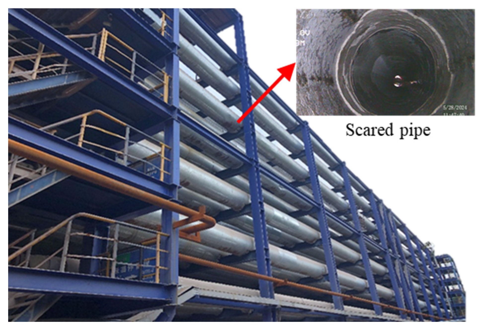
Figure 16: Test cleaning object.
4.2 High-Pressure Water Jet Cleaning Test
The numerical simulation results show that the tapered nozzle has an extended taper section, which results in a jet with minimal divergence, enhanced stability, and highly concentrated flow. These attributes contribute to a jet performance that outperforms both flat and conical nozzles in terms of cleaning efficiency. Following the simulation analysis, a model of the reduced nozzle is fabricated, and a series of cleaning effect tests are conducted on tapered nozzles with varying outlet diameters. The experimental conditions and parameters are summarized in Table 3.
Table 3: High-pressure water jet cleaning test table.
| Working Condition | Outlet Diameter (mm) | Target Range (mm) | Impact Angle (°) | Cleaning Pressure (MPa) | Cleaning Time (min) |
|---|---|---|---|---|---|
| 1 | 0.8 | 15 | 75 | 130 | 40 |
| 2 | 1.0 | 15 | 75 | 130 | 40 |
| 3 | 1.2 | 15 | 75 | 130 | 40 |
The test results presented in Fig. 17 reveal a clear correlation between the nozzle outlet diameter and cleaning effectiveness. When the nozzle outlet diameter is 0.8 mm, the relatively small outlet diameter results in a concentrated jet stream, causing the jet cluster to be highly focused. This concentration of energy leads to cleaning traces that are narrow and sparse, ultimately resulting in suboptimal cleaning performance. Increasing the nozzle outlet diameter to 1.0 mm yields a slight improvement in the cleaning effect, as evidenced by the broader cleaning traces, although a small area of the tube wall remains dark, indicating incomplete cleaning. In contrast, when the nozzle outlet diameter is further increased to 1.2 mm, the flow rate is fully utilized, leading to the most effective cleaning outcome. At this diameter, the cleaning marks are significantly wider, and the pipe wall color is more uniformly exposed, indicating a more thorough and efficient cleaning process.
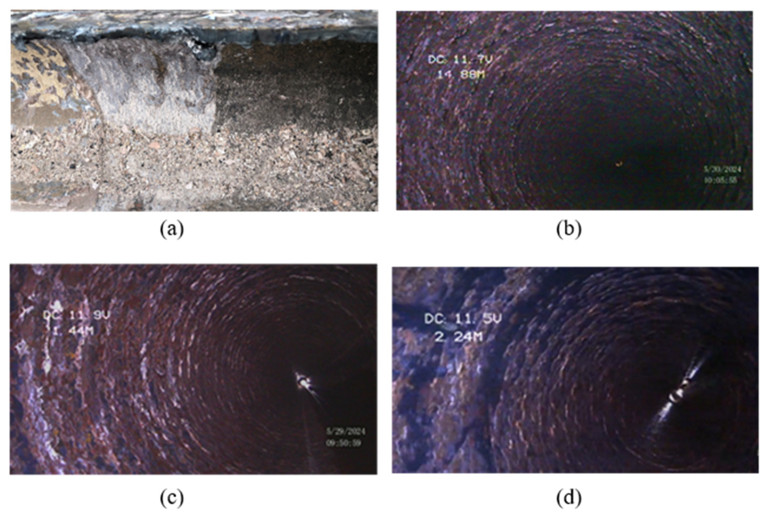
Figure 17: Test result. (a) Before cleaning; (b) d = 0.8 mm; (c) d = 1.0 mm; (d) d = 1.2 mm.
Test images are captured using an endoscope with an integrated LED light source. The resulting RGB images are converted to grayscale images, and the corresponding grayscale histograms are generated to quantify the test results. Fig. 18 shows the grayscale processed images and corresponding grayscale histograms after cleaning the actual pipeline with nozzle exit diameters of 0.8, 1.0, and 1.2 mm. In these images, each pixel has a grayscale value from 0 (black) to 255 (white), with intermediate values representing shades of gray. The histogram’s horizontal axis denotes the gray level, and its vertical axis represents the frequency of each level within the image. In industrial cleaning, the pipe wall is typically dark, whereas scale deposits are lighter. Effective cleaning process is quantitatively demonstrated by a significant increase in the relative surface area coverage of the darker pipe wall region post-treatment, indicating effective scale removal. Based on actual cleaning requirements and test results, 40 is defined as the threshold.
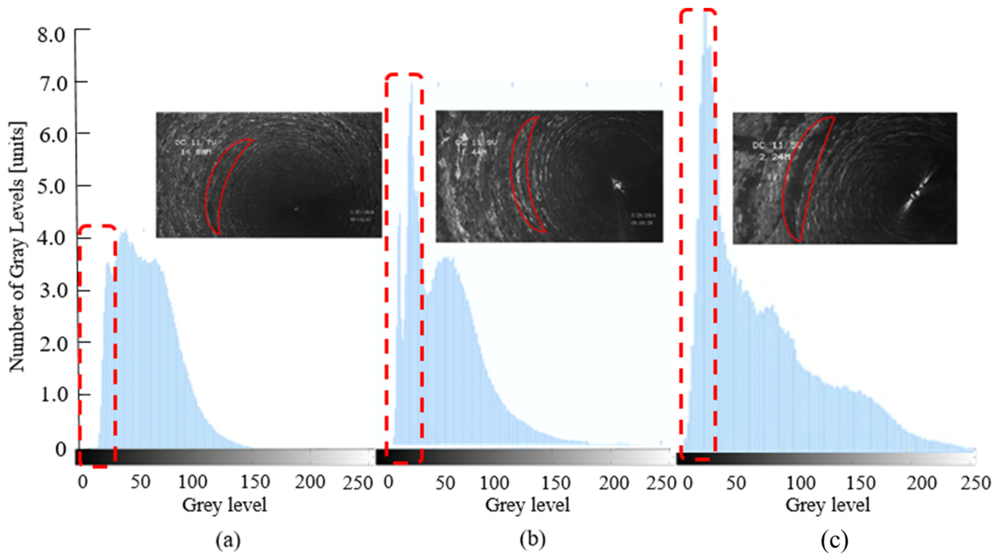
Figure 18: Gray image and gray histogram. (a) d = 0.8 mm; (b) d = 1.0 mm; (c) d = 1.2 mm.
Effective effect is considered to be achieved when the gray value is less than or equal to 40. For the nozzle with a 0.8 mm outlet diameter, the number of pixels with a gray level greater than or equal to 40 is 80.77 × 10⁴. For the 1.0 and 1.2 mm nozzle, these values are 89.06 × 10⁴ and 125.08 × 10⁴, respectively. The gray levels for the 0.8 and 1.0 mm nozzles are primarily concentrated within the range of 41–80, while for the 1.2 mm nozzle, the gray levels are predominantly concentrated in the range of 0–40. When the nozzle outlet diameter is increased from 0.8 to 1.2 mm, the cleaning effect improves by 40.44%, as the data in Fig. 19 demonstrate.
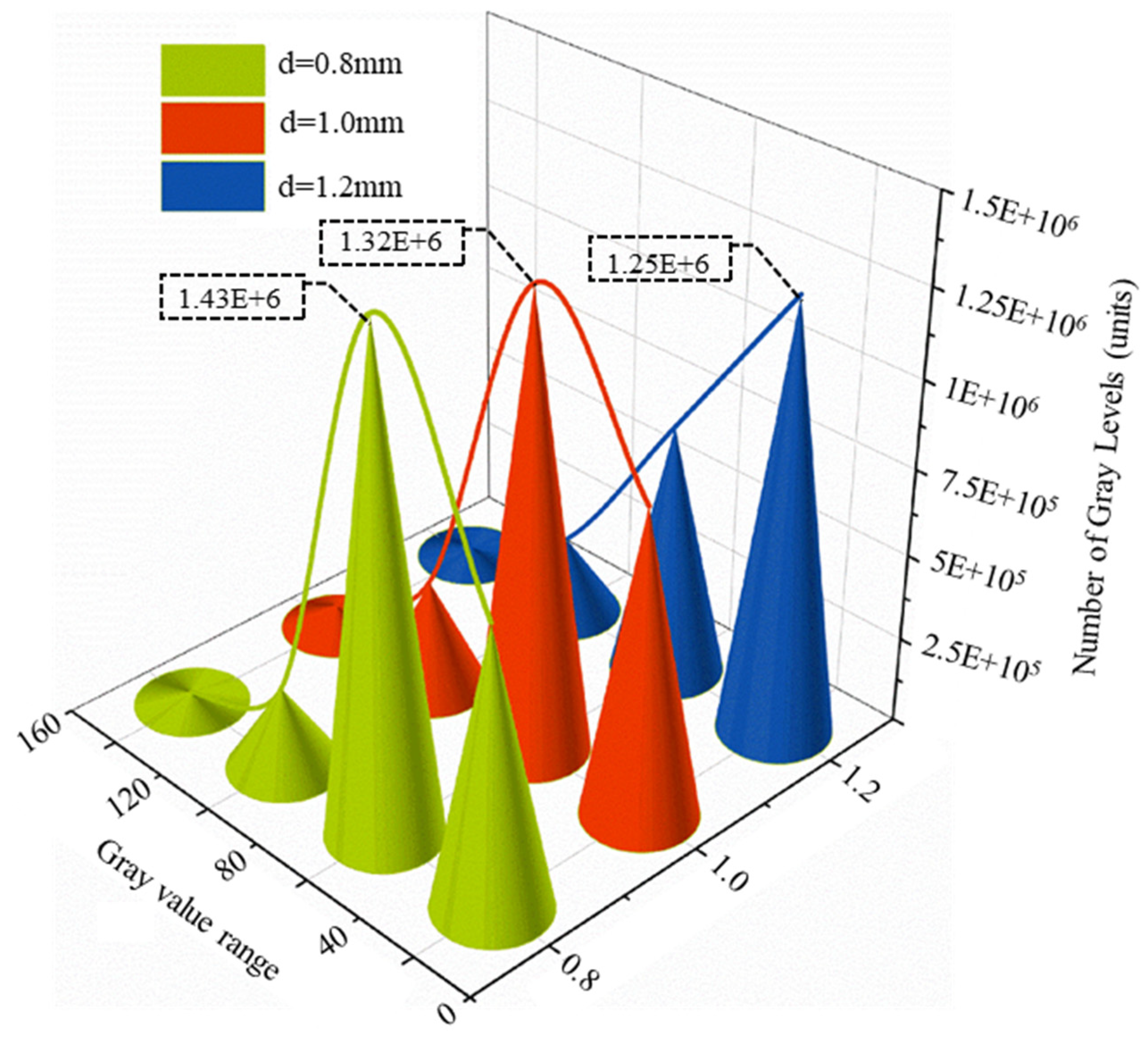
Figure 19: The number of gray values in each gray level.
A comparison is made between the numerical simulation results, represented by the area of the target surface with a total pressure value exceeding 120 MPa, and the experimental results, derived from grayscale values. It is found that the two trends are highly consistent for the three nozzle exit diameters as shown in Fig. 20. The nozzle with the maximum outlet diameter exhibits the highest values in both numerical simulations and tests, including the maximum total pressure on the target surface and the maximum gray value. The correlation coefficient between the numerical simulation results and the experimental results, r = 0.98, indicates that there is an extremely strong linear relationship between them. In addition, the t-test shows a p-value of 0.867 (>0.05), indicating that the numerical simulation results are not significantly different from the experimental results. The numerical simulation results are highly consistent with the experimental data, verifying the accuracy of the numerical modeling. Despite the large relative error in the second data point, the overall trend shows that the numerical simulation results are highly consistent with the experimental data, validating the accuracy of the numerical model. Future research could further analyze the causes of local deviations to optimize model performance (Table 4).
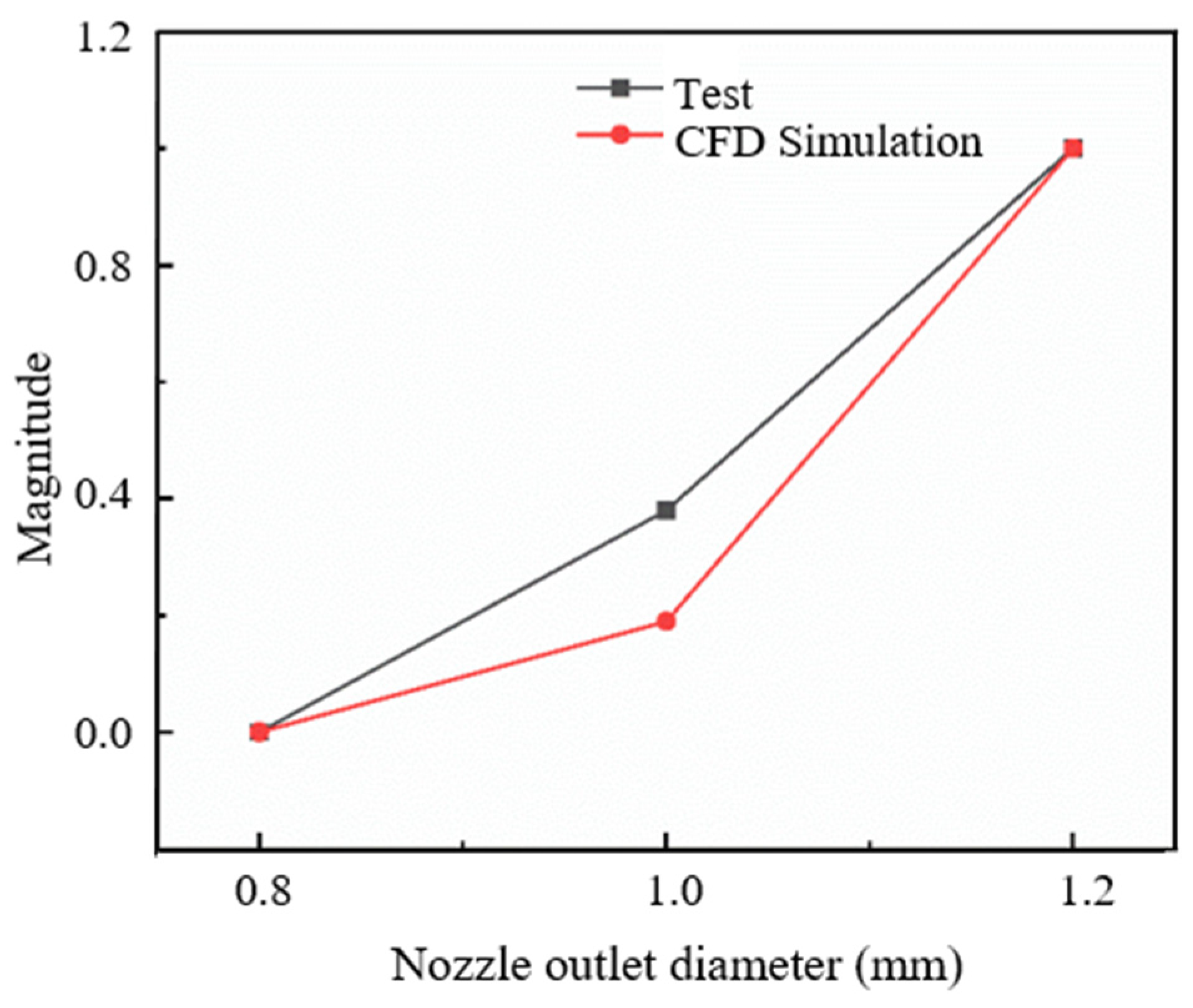
Figure 20: Comparison of test results and simulation results.
Table 4: Comparison of test results and simulation results data.
| Outlet Diameter (mm) | Area (mm2) | Number of Gray Levels (×104) | Normalize | |
|---|---|---|---|---|
| 0.8 | 0 | 80.77 | 0 | 0 |
| 1.0 | 0.51 | 89.06 | 0.38 | 0.19 |
| 1.2 | 1.33 | 125.08 | 1 | 1 |
This study evaluates the jet behavior of high-pressure nozzles through a combined numerical-experimental approach. The high correlation between simulated and measured data provides a basis for developing a nozzle selection framework that enhances cleaning efficiency. The research findings are as follows:
- (1)The fluid velocity gradient varies most significantly in the nozzle’s converging and straight sections. Taper-type nozzles have a long tapered section that helps stabilize the jet. Consequently, the jet has a small divergence angle, high stability and a concentrated beam.
- (2)An increase in the nozzle outlet diameter enlarges the core area of the jet’s main flow, leading to greater jet stability and a reduction in the range of dynamic pressure decay. When the nozzle outlet diameter is increased from 0.8 to 1.2 mm, the dynamic pressure at the nozzle outlet increases by 1.24% and the total pressure at the target surface increases by 33.14%.
- (3)Cleaning tests indicate that a nozzle with 1.2 mm outlet diameter allows the unit flow rate to be fully realized. This results in a wider cleaning mark and exposes the darker pipe wall beneath. The 1.2 mm nozzles outperform 1.0 and 0.8 mm nozzles, demonstrating a 40.44% improvement in cleaning performance.
Acknowledgement:
Funding Statement: This research was funded by the Natural Science Foundation of Shandong Province, China (No. ZR2021QE157).
Author Contributions: The authors confirm contribution to the paper as follows: study conception and design: Yuxin Wang, Youjiang Wang, Jieping Wang, Yongxing Song. Analysis of results: Chao Zhang, Fanguang Meng, Linhua Zhang. All authors reviewed the results and approved the final version of the manuscript.
Availability of Data and Materials: The data that support the findings of this study are available from the Corresponding Author, upon reasonable request.
Ethics Approval: Not applicable.
Conflicts of Interest: The authors declare no conflicts of interest to report regarding the present study.
References
1. Askarian M , Ben Dhieb F , Fadaei H , Safizadeh F , Alizadeh E , Latifi M . Improved α-alumina production by seed-assisted aluminum chloride hexahydrate crystallization approach. Ceram Int. 2025; 51( 28 Pt A): 56783– 91. doi:10.1016/j.ceramint.2025.09.392. [Google Scholar] [CrossRef]
2. Wang P , Liu Q , Xu D , Peng W , Liu F , Hou J , et al. Investigation of fouling development and kinetics in titanium alloy seawater heat exchanger tubes. Int J Heat Fluid Flow. 2026; 117: 110107. doi:10.1016/j.ijheatfluidflow.2025.110107. [Google Scholar] [CrossRef]
3. Alsadaie SM , Mujtaba IM . Dynamic modelling of Heat Exchanger fouling in multistage flash (MSF) desalination. Desalination. 2017; 409: 47– 65. doi:10.1016/j.desal.2017.01.020. [Google Scholar] [CrossRef]
4. Kapustenko P , Klemeš JJ , Arsenyeva O . Plate heat exchangers fouling mitigation effects in heating of water solutions: A review. Renew Sustain Energy Rev. 2023; 179: 113283. doi:10.1016/j.rser.2023.113283. [Google Scholar] [CrossRef]
5. Song X , Liu J , Fei L , Zhang W . Performance of an electro-optic-liquid coupling nozzle with a multi-jet focusing structure. Fluid Dyn Mater Process. 2025; 21: 1379– 96. doi:10.32604/fdmp.2025.061222. [Google Scholar] [CrossRef]
6. Ghahfarokhi PS , Podgornovs A , Cardoso AJM , Rasilo P . Assessment of nozzle performance in high-viscosity oil spray system for rectangular copper conductors. Int J Therm Sci. 2024; 204: 109244. doi:10.1016/j.ijthermalsci.2024.109244. [Google Scholar] [CrossRef]
7. Hong TD , Pham MQ , Huynh TP , Vu TV , Tran LQ . Removal of the iron oxide layer from a fuel tank wall: effect of nozzle distance and impact angle on water jet pressure. Results Phys. 2025; 73: 108278. doi:10.1016/j.rinp.2025.108278. [Google Scholar] [CrossRef]
8. Tan S , Xu X , Qi Y , Ni R . Scalings and decay of homogeneous, nearly isotropic turbulence behind a jet array. Phys Rev Fluids. 2023; 8: 024603. doi:10.1103/PhysRevFluids.8.024603. [Google Scholar] [CrossRef]
9. Deng K , Zhou N , Lin Y , Cheng J , Bing L , Jing Z . Experimental and numerical study on the high-speed gas-solid nozzle erosion of choke manifold material in high pressure and high production gas well. Powder Technol. 2024; 438: 119628. [Google Scholar]
10. Blanco D , Muñoz-Cobo JL , Berna C . Experimental analysis of jet expansion geometry and the influence of pressure waves on the behavior of air discharge processes in subcooled stagnant water. Nucl Eng Technol. 2025; 57: 103768. doi:10.1016/j.net.2025.103768. [Google Scholar] [CrossRef]
11. Zou X , Fu L , Wu L . Multiphase flow and nozzle wear with CFD-DEM in high-pressure abrasive water jet. Powder Technol. 2024; 444: 120019. doi:10.1016/j.powtec.2024.120019. [Google Scholar] [CrossRef]
12. Huang L , Chen Z . Effect of technological parameters on hydrodynamic performance of ultra-high-pressure water-jet nozzle. Appl Ocean Res. 2022; 129: 103410. [Google Scholar]
13. Jiang M , Sun B , Niu Y , Liu Y , Long Z , Bu X . Insights and simulation models for long-distance water jet mining: evolution of breaking depth and mass. Process Saf Environ Prot. 2025; 195: 106761. doi:10.1016/j.psep.2025.01.015. [Google Scholar] [CrossRef]
14. Fang Z , Qiao W , Mo C , Li J , Yang L , Fu Q . Experimental study of cryogenic jet injection using centrifugal nozzles at supercritical pressure. Acta Astronaut. 2024; 221: 240– 54. doi:10.1016/j.actaastro.2024.05.025. [Google Scholar] [CrossRef]
15. Bukane SV , Shaikh VA . Nanocoated solar panel cleaning system using high pressure water jet nozzle. AIP Conf Proc. 2024:3122; 100022. doi:10.1063/5.0216242. [Google Scholar] [CrossRef]
16. Ferrer R , Verlinde M , Verstraelen E , Claessens A , Huyse M , Kraemer S , et al. Hypersonic nozzle for laser-spectroscopy studies at 17 K characterized by resonance-ionization-spectroscopy-based flow mapping. Phys Rev Res. 2021; 3: 043041. doi:10.1103/PhysRevResearch.3.043041. [Google Scholar] [CrossRef]
17. Wee H , Kumar AH , Dhanwani NK , Basaran OA . Slender-jet equations with surface rheological effects and the Newtonian limit. Phys Rev Fluids. 2024; 9: 113602. doi:10.1103/PhysRevFluids.9.113602. [Google Scholar] [CrossRef]
18. Ma Y , Zhao W , Zhang H , Ma L , Fan C , Zhang X , et al. A new method for laser grooving titanium alloy with the assist of a hybrid of gas jet waterjet. J Mater Process Technol. 2023; 315: 117906. doi:10.1016/j.jmatprotec.2023.117906. [Google Scholar] [CrossRef]
19. Qiu Y , Lan X , Liu J , Wang G , Huang Z . Optimization design of nozzle parameters under the condition of submerged water jet breaking soil based on response surface method. Appl Ocean Res. 2025; 154: 104369. doi:10.1016/j.apor.2024.104369. [Google Scholar] [CrossRef]
20. Longobardo G , Paolillo G , Cardone G , Astarita T , Greco CS . Effects of the nozzle-to-plate distance and nozzle exit section shape on the heat transfer behaviour of impinging synthetic jets. Int J Heat Mass Transf. 2026; 254: 127661. doi:10.1016/j.ijheatmasstransfer.2025.127661. [Google Scholar] [CrossRef]
21. Zhong W , Chen J , Li C , Huang Y , Pachiannan T , Jiang Z , et al. Visualization study on flash boiling spray characteristics of high-pressure liquid ammonia with different nozzle diameters. Fuel. 2024; 367: 131525. doi:10.1016/j.fuel.2024.131525. [Google Scholar] [CrossRef]
22. Wang P , Zhou X , Li X , Chen Z , Hu Q , Wang X , et al. Numerical experimental investigation of close-coupled twin-nozzle gas atomization towards fine high-entropy alloy powder production. J Mater Process Technol. 2024; 324: 118238. doi:10.1016/j.jmatprotec.2023.118238. [Google Scholar] [CrossRef]
23. Bhavsar H , Mistry C . Numerical study on impact of circular pivot sizes on part clearance flow structure and loss mechanism within variable area low pressure turbine nozzle vanes. Aerosp Sci Technol. 2025; 165: 110497. doi:10.1016/j.ast.2025.110497. [Google Scholar] [CrossRef]
24. Liu Y , Wei J . On the formation mechanism and characteristics of high-pressure percussion pulsed water jets. Fluid Dyn Mater Process. 2015; 11: 221– 40. doi:10.3970/fdmp.2015.011.221. [Google Scholar] [CrossRef]
25. Alhaddad S , Snyder A , Bult SV , Keetels G . Experimental investigation of cohesive soil erosion caused by translating submerged inclined water jets. Appl Ocean Res. 2025; 157: 104486. doi:10.1016/j.apor.2025.104486. [Google Scholar] [CrossRef]
26. Yin P , Yang S , Li X , Xu M . Numerical simulation of in-nozzle flow characteristics under flash boiling conditions. Int J Multiph Flow. 2020; 127: 103275. doi:10.1016/j.ijmultiphaseflow.2020.103275. [Google Scholar] [CrossRef]
27. Garoosi F , Hooman K . Numerical simulation of multiphase flows using an enhanced Volume-of-Fluid (VOF) method. Int J Mech Sci. 2022; 215: 106956. doi:10.1016/j.ijmecsci.2021.106956. [Google Scholar] [CrossRef]
28. Yuan J , Liu L , Bao R , Li D , Tian X , Luo H , et al. Numerical simulation of jet boiling characteristics of high-pressure water injected into high-temperature liquid lead–bismuth in a confined space. Appl Therm Eng. 2024; 250: 123432. doi:10.1016/j.applthermaleng.2024.123432. [Google Scholar] [CrossRef]
29. Cao Z , Wang M , Yan S , Zhao C , Liu H . Surface integrity material removal mechanism in fluid jet polishing of optical glass. J Mater Process Technol. 2023; 311: 117798. doi:10.1016/j.jmatprotec.2022.117798. [Google Scholar] [CrossRef]
30. Fard MG , Nag A , Petrů J , Hloch S . Towards sustainable precision: a review of water jet meso and micromachining. Results Eng. 2025; 27: 106447. doi:10.1016/j.rineng.2025.106447. [Google Scholar] [CrossRef]
31. Zhang S , Tao X , Lu J , Wang X , Zeng Z . Design optimization and CFD simulation of a nozzle for industrial cleaning processes based on high-pressure water jets. Fluid Dyn Mater Process. 2015; 11: 143– 55. doi:10.3970/fdmp.2015.011.143. [Google Scholar] [CrossRef]
32. Vasudevan B , Nagarajan L , Siddiqui MIH , Nachippan NM , Palani S , Natarajan Y . Investigating abrasive water jet drilling of YSZ-Coated inconel 718: a surface topography and morphology study. Mater Chem Phys. 2025; 341: 130926. doi:10.1016/j.matchemphys.2025.130926. [Google Scholar] [CrossRef]
33. Shiraishi R , Kuwaki Y , Hatayama T , Sakamoto S , Yamasaki C , Hayamizu Y , et al. Improvement in ammonia production efficiency via collision of fine water droplets with a nitrogen plasma jet. Int J Hydrogen Energy. 2025; 184: 151825. doi:10.1016/j.ijhydene.2025.151825. [Google Scholar] [CrossRef]
Cite This Article
 Copyright © 2025 The Author(s). Published by Tech Science Press.
This work is licensed under a Creative Commons Attribution 4.0 International License , which permits unrestricted use, distribution, and reproduction in any medium, provided the original work is properly cited.
 Downloads
 Citation Tools