
 Submit a Paper
 Propose a Special lssue
 Open Access
ARTICLE

Inertial Modes in a Rotating Horizontal Annulus with Boundaries of Different Temperatures and Their Effect on the Averaged Convection
Laboratory of Vibrational Hydromechanics, Perm State Humanitarian Pedagogical University, Perm, 614990, Russia
* Corresponding Author: Alexey Vjatkin. Email:
(This article belongs to the Special Issue: Non-Equilibrium Processes in Continuous Media)
Fluid Dynamics & Materials Processing 2025, 21(4), 783-798. https://doi.org/10.32604/fdmp.2025.062535
Received 20 December 2024; Accepted 13 February 2025; Issue published 06 May 2025
 View Full Text
 Download PDF
Abstract
Time-averaged thermal convection in a rotating horizontal annulus with a higher temperature at its inner boundary is studied. The centrifugal force plays a stabilizing role, while thermal convection is determined by the “thermovibrational mechanism”. Convective flow is excited due to oscillations of a non-isothermal rotating fluid. Thermal vibrational convection manifests in the form of two-dimensional vortices elongated along the axis of rotation, which develop in a threshold manner with an increase in the amplitude of fluid oscillations. The objective of the present study is to clarify the nature of another phenomenon, i.e., three-dimensional convective vortices observed in the experiments both before the excitation of the convection described above and in the supercritical region. The experimental study of the oscillatory and the time-averaged flow fields by particle image velocimetry is accompanied by the theoretical research of inertial waves. It is found that three-dimensional fluid flows owe their origin to inertial waves. This is confirmed by a high degree of agreement between the experimental and theoretical results. Experiments with cavities of different lengths indicate that the vortices are clearly seen in cavities that meet the conditions of resonant excitation of inertial modes. Furthermore, the length of the cavity has no effect on heat transfer, which is explained by the comparatively low intensity of the wave-induced flows. The main contribution to heat transfer is due to vortices elongated along the axis of rotation. The novel results are of significant practical importance in various fields.Keywords
The phenomenon of thermal convection in rotating systems is a subject of great interest to many researchers [1–4]. This is due to the widespread presence of this phenomenon in nature (liquid cores and atmospheres of planets) and technology [5–7]. The diversity and complexity of thermal convection problems during rotation are determined by the action of the centrifugal force of inertia and the Coriolis force [8]. In this context, the oscillations of rotating fluids play a significant role, manifesting specific features and giving rise to a range of time-averaged (steady) flows [9,10].
Interest in studying the influence of vibrations and rotation on thermal convection is determined by the development of effective tools for vibration control over heat and mass transfer. These tools are of significant importance in the production of functional materials, as evidenced by their application in the process of crystal growth from a melt [11]. Due to the action of the Coriolis force and the centrifugal force of inertia Rotation significantly expands the spectrum of natural frequencies of a non-isothermal hydrodynamic system [12], which allows for a calibrated influence on crystallization processes by controlling mechanical and chemical equilibrium, the structure of convective flows, phase boundaries, etc.
One example of the time-averaged flows in a non-isothermal fluid is “thermal vibrational convection” which refers to the convection of a non-isothermal fluid excited by a force oscillating in the cavity reference frame. The term vibrational is used in reference to an oscillatory force field that may be of an inertial nature, i.e., induced by the cavity vibrations. This phenomenon has been studied theoretically and experimentally in the absence of rotation [13]. The generation mechanism of the averaged lift force in a non-isothermal liquid in an oscillating force field is as follows: a liquid with a non-uniform temperature (and therefore density) oscillates in an oscillating force field, which in turn leads to a harmonic change in the temperature field (density field) of the liquid. The frequency of liquid oscillations coincides with the frequency of the inertial field oscillations; the process is accompanied by the generation of the time-averaged lift force. The non-linear term also makes its contribution to the period-averaged mass force. This phenomenon is described in the theoretical and experimental works of the Perm Hydrodynamic School in the limit of high-frequency translational oscillations [13]. The high frequency limit indicates that the oscillating viscous and temperature boundary layers are of negligible size in comparison to the characteristic dimension of the problem. This implies that the fluid oscillations can be considered inviscid. In the case of high-frequency translational vibrations of the cavity with an amplitude
Here,
Thermal vibrational convection in rotating systems has been studied experimentally and theoretically [21–23]. In the case of cavities rotating around a horizontal axis in a gravity field, “vibrational” convection is excited in the absence of any vibrations. A feature of rotating systems is that the Coriolis force has a stabilizing effect on the three-dimensional flow [20]. Therefore, the generation of 2D convective flows in the form of vortices elongated along the axis of rotation is observed in experiments with rapidly rotating containers. Note that the time-averaged convection can be excited even in a fluid that is stably stratified in a centrifugal field, for example, in a cylindrical layer with a hot internal boundary rotating around a horizontal axis [24]. The focus of the listed experiments and theoretical calculations is primarily on the consideration of two-dimensional convective flows in rotating cavities, where the effect of the Coriolis force on the time-averaged flows does not manifest itself. In the case of three-dimensional convective flows, the Coriolis force has a significant stabilizing effect on the convective vortices [25,26]. It is important to note that the Coriolis force also significantly affects the oscillations of the non-isothermal fluid, changing the mechanism of thermal vibrational convection. One of the effects associated with the Coriolis force is the excitation of inertial waves [8], which modify the convective flows in rotating flat layers [25,26] and in axisymmetric cavities. For example, in a rotating cylinder with internal heat release [21], the excitation of toroidal vortices is observed before the excitation of two-dimensional convective patterns. Similar three-dimensional convective flows, presumably associated with the action of inertial waves, are observed in rotating annuli [22,24].
Thermal convection in a rotating annulus allows us to clarify the effect of rotation on thermal convection. Theoretical and experimental studies of convection are known in the case of classical centrifugal convection when the outer boundary has a higher temperature [27,28]. The aim of this study is to investigate inertial wave oscillations and thermal convection excited against their background. The novelty of the study is that the inner boundary has a higher temperature, the centrifugal force has a stabilizing effect on the non-isothermal fluid, and the thermal convection is excited by the gravitational force rotating in the cavity reference frame. The work is a continuation of the research [22], in which toroidal vortices, periodically located along the axis of rotation, were discovered. The study was conducted in the same statement, where the vibrational thermal convection (2) and the centrifugal convection, characterized by the centrifugal Rayleigh number.
are observed. Here,
2 Experimental Setup and Techniques
The present study examines the phenomenon of thermal convection in a rotating horizontal annulus with boundaries of different temperatures in relation to the length of the cavity. The cavity consists of aluminum cylinder 1 and transparent Plexiglas pipes 2 and 3 (Fig. 1). The annulus is a space between the aluminum heat exchanger 1 and the pipe 2. The inner and outer radii of the annulus are
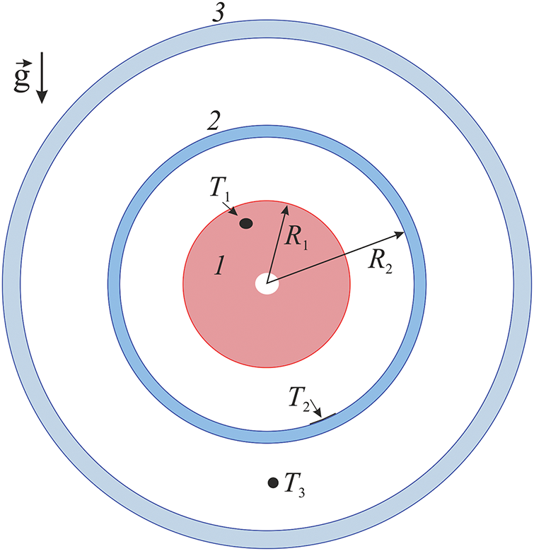
Figure 1: Formulation of the problem
The working fluid in the experiments is water. The temperature
The experimental procedure is as follows. Once the electric heater has been activated and the cooling water in the jacket has reached a specified temperature (typically 20°С), the experiment is initiated at a relatively high angular velocity
The working fluid is distilled water. The equilibrium temperature distribution and the temperature difference
The velocity flow field is examined using particle image velocimetry. For this purpose, a DPSS laser KLM-532/h-1000 and a high-speed camera CamRecord CL600x2 are employed (Fig. 2), with subsequent image processing carried out using the PIVlab software [32]. The camera is positioned along the axis of rotation. The light sheet is used to illuminate the annulus in cross-section at a given distance from the cavity end wall. Spherical polyamide particles with a diameter of 20 µm and a density of 1.04 g/cm3 are added to the fluid. The frame rate is a multiple of the annulus rotation rate and ranges from 20 to 64 fps at a resolution of 800 × 800 pixels. The image sequence is rotated against the direction of rotation by an angle dependent on the frame rate to study the fluid flow in the cavity reference frame. To illustrate, at a rotation rate of
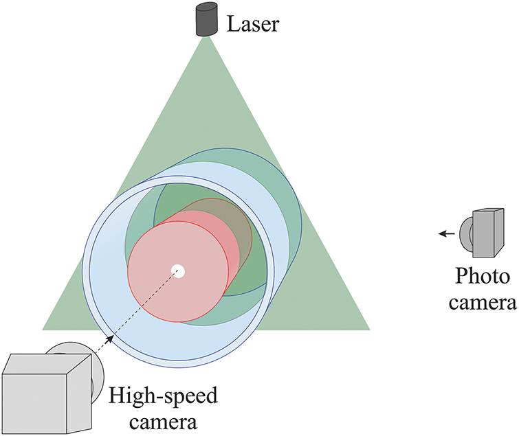
Figure 2: Scheme of the experimental setup
The visualization of convective flows is enabled by the addition of aluminum powder to the fluid. Additionally, a minimal amount of surfactant is added to the fluid to prevent the powder particles from adhering to the cavity walls. The powder has a greater density than the fluid so the particles accumulate near the outer boundary of the annulus under the action of the centrifugal force of inertia. The heterogeneity of the powder concentration near the outer boundary enables an investigation of the flow pattern [24].
3.1 Heat Transfer and Temperature Distribution
Fig. 3 demonstrates the results of the temperature difference measurements taken at various power levels P at a gradual reduction of the rotation rate. At rapid rotation,
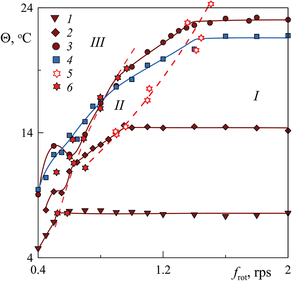
Figure 3: Dependence of the temperature difference
Here, regions II and III correspond to different regimes of the vibrational convection. A detailed description of the regimes in these regions can be found in [24], where a cavity of a length
Photo recording is carried out using aluminum powder added to a liquid. The powder particles are distributed near the external boundary of the annulus under the influence of centrifugal force. The photos in Fig. 4 illustrate the distribution of the powder particles in cavities of different lengths (the front annulus boundary undergoes an upward motion from the perspective of the observer). Here, the heat exchanger coated with a black film is distinctly visible in the center of the images.
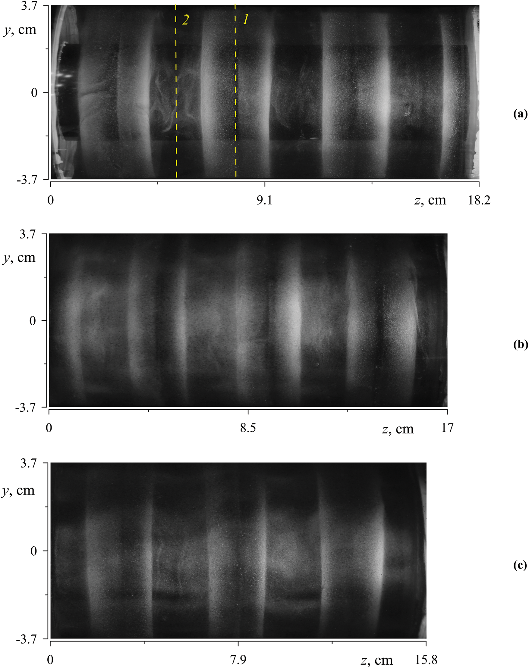
Figure 4: Photos of annuli of different lengths obtained under conditions of the region II: (a–c)
One can find that the particles display a tendency to accumulate in band-like patterns (white stripes in Fig. 5a) which are located at equal distances along the cavity axis. There is a distinct absence of aluminum powder in the center of each band, resulting in the formation of a black stripe. Additionally, the contours of the bands appear to be indistinct. The bands of aluminum powder indicate a series of vortices within the annulus. It is important to note that the toroidal vortices are present in all regimes (areas I, II, and III) and have a weak effect on the temperature difference (heat transfer) in area I.
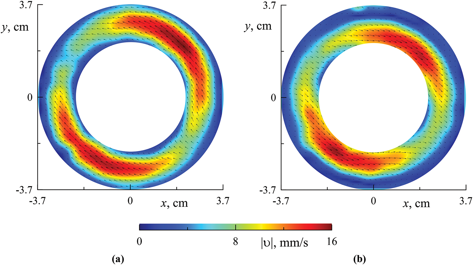
Figure 5: The velocity flow field at different axial positions: (a) cross-Section 1 (dashed line in 1 in Fig. 4a); (b) cross-Section 2 (dashed line 2 in Fig. 4a); (a, b)
The photographs in Fig. 4 illustrate the spatially periodic distribution of powder concentration in the form of light (high concentration) and dark (low concentration) bands that mark the geometry of the toroidal vortices carrying the powder particles. The center of a light or dark band is located at the end wall of the cavity. As will be shown below, the powder particles accumulate due to the excitation of a standing (along the axis of rotation) inertial wave, also called an inertial mode. Additionally, the axial velocity nodes of a given standing wave are located at the cavity end walls. It is clearly seen that the spatial period (the distance between the centers of the light bands) changes weakly with the length of the cavity: The number of bands decreases with decreasing cavity length. It is noteworthy that in the long cavity, the center of the light band is located near one end wall, while the center of the dark band is near the other end wall (Fig. 4a). The centers of the dark bands in the short annulus (Fig. 4c) are close to the end walls. It can be assumed that the short and long cavities meet the condition of spatial resonance. In the mid-length annulus (Fig. 4b), the bands appear to be blurred. Let us now consider the velocity flow field at different cross-sections along the cell length.
Fig. 5 shows the velocity flow fields obtained by the PIV technique in the annulus reference frame at different axial positions indicated in Fig. 4a. In the cavity reference frame, the flow velocity results from the superposition of two components: first, the oscillating component associated with the inertial oscillations and second, the time-averaged component, which is attributed to the time-averaged thermal vibrational flow. Since the time-averaged flow is considerably weaker than the oscillatory one, we see the inertial wave-induced instantaneous velocity fields. The fluid flow is prograde near the rising cavity wall (the left wall in Fig. 5a) while the flow is retrograde near the descending wall (the right wall in Fig. 5a) in cross-Section 1. It can be concluded that the azimuthal wavenumber of the inertial wave is equal to one, and the fluid oscillates in anti-phase at the opposite positions of the annulus relative to the rotation axis. It is important to note that the flow field remains constant over time in the laboratory reference frame. This indicates that the azimuthal velocity of the wave is equal to the rotation rate of the annulus, yet it rotates in a direction opposite to that of the annulus. It can be stated that the wave-induced oscillations occur with a relative frequency of
A comparison of the instantaneous velocity fields of the wave-induced fluid motion in Sections 1 and 2 provides crucial insight into the structure of the inertial wave (Fig. 5a and b). It can be observed that the fluid in these sections moves in opposite directions, indicating that the fluid oscillates in anti-phase. As shown below, the selected cross-sections are located at the nodes of the axial velocity of the inertial mode (the inertial wave standing along the rotation axis). This condition is also met by the end walls of the cavity, on which one of two cross-sections is located: the center of the light band (1) or the center of the dark band (2). It should be noted that the nodes of the axial velocity correlate with the pressure antinodes. Consequently, the fluid oscillates in antiphase at the neighboring nodes of the standing wave, and thus the wavelength of the standing inertial wave is twice the distance between the pressure or axial velocity nodes.
Interesting information is provided by photos of convective flows in the supercritical region (region III in Fig. 3). As demonstrated in [22], thermal vibrational convection takes the form of a series of two-dimensional vortices elongated along the annulus axis. The vortices undergo a slow retrograde azimuthal drift relative to the rotating cavity. The use of neutrally buoyant tracer particles allows for the visualization of vortices in quasi-stationary shear flows. In the presence of a weak inertial wave, suspended tracer particles indicate two-dimensional vortices that are elongated along the rotation axis. However, under conditions of intense inertial oscillations, the wave manifests itself in a retrograde azimuthal fluid drift in cross-Section 1 near the descending wall of the annulus (right-hand side in Fig. 5a). Also, the prograde fluid motion in the vicinity of the descending wall is observed in the cross-Section 2 (right-hand side in Fig. 5b). The combined effect of the prograde and retrograde motions results in the bending of the two-dimensional convective vortices, as illustrated in Fig. 6. In cross-Section 1, the velocity of the azimuthal oscillatory flow in the annulus reference frame is positive, resulting in a bending of the convective vortex in the direction of rotation. Also, the oscillation velocity in cross-Section 1 in the vicinity of the descending wall is identified to have a negative value. The direction of fluid motion in cross-Section 2 is opposite to that observed in cross-Section 1. The combined effect of these flows gives rise to a wave-like bending of the vortices, which depends on the azimuthal angle of annulus rotation. The findings of these observations are in accordance with the results of measurements of the velocity field in the cross-section of the rotating annulus (Fig. 5).
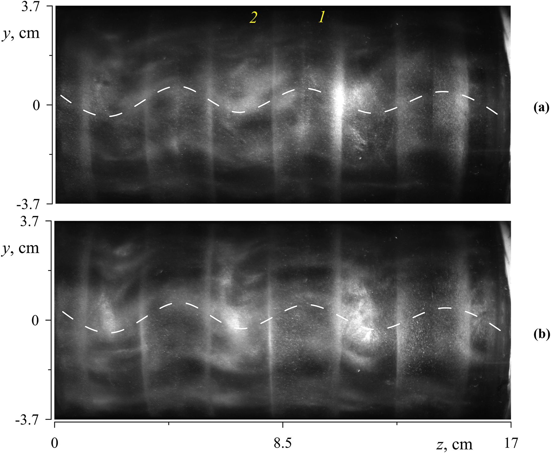
Figure 6: Side view of the convective vortices in the region III: (a) rising wall; (b) descending wall; (a, b)
The experimental study leads to the conclusion that in a rotating annulus with boundaries of different temperatures, an inertial standing wave is excited. The wave propagates in the azimuthal direction at the same rate as the cavity rotates but in the opposite direction. As will be demonstrated below, the wave-induced pressure perturbation can be represented as follows
3.3 Effect of Inertial Waves on the Onset of Thermal Convection and Heat Transfer in the Supercritical Region
As illustrated in Fig. 3, the conditions governing the transition from one convection regime to another remain independent of the cavity length. The vibrational parameter
It is also important to note that the cavity length, and therefore the conditions for the inertial waves’ excitation, has no effect on the heat transfer. Fig. 7 demonstrates that the Nusselt number is independent of the annulus length. The measurement results obtained in annuli of different lengths are consistent with one another in different convection regimes. Here, regions I, II, and III correspond to those illustrated in Fig. 3.
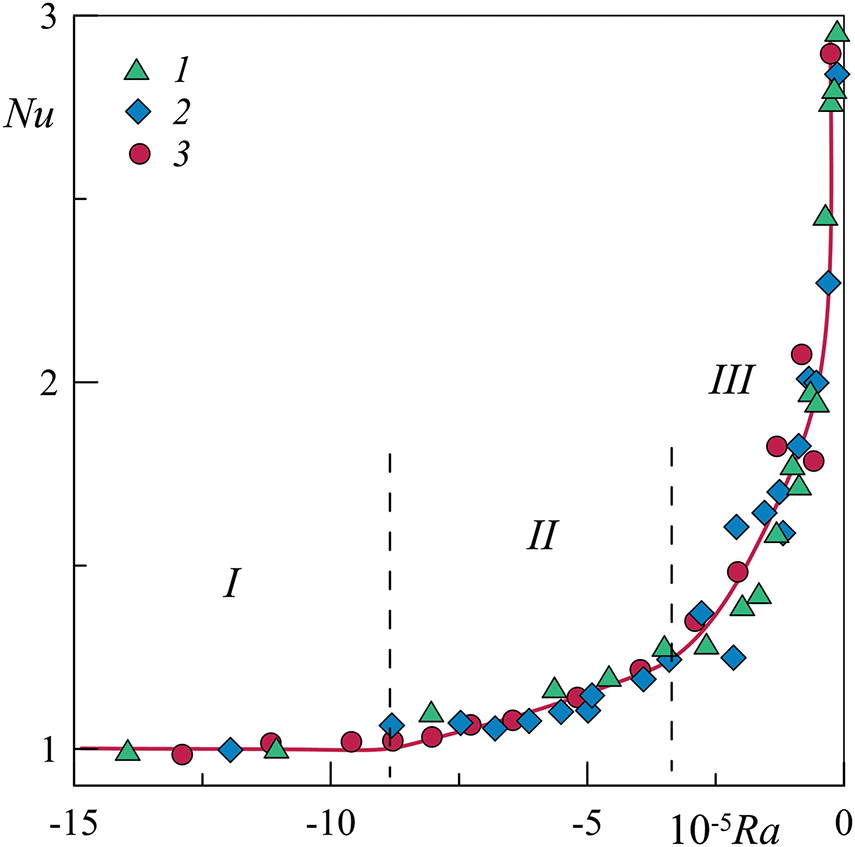
Figure 7: Dependence of the Nusselt number Nu on the centrifugal Rayleigh number Ra in annuli of different lengths: (1)
As will be demonstrated below, the longest and shortest annuli satisfy the spatial resonance condition. A comparison of the results obtained in different annuli demonstrates that the impact of inertial waves on the stability threshold and heat transfer is independent of the annuli length. On the one hand, this can be explained by a comparatively small contribution of inertial wave flows to heat transfer in the subthreshold region (Fig. 7); and in the supercritical region thermovibrational cellular convection plays the dominant role. On the other hand, the conditions of the resonant length of the cavity may not be determining. This can be expected if a wave of a certain length is generated by periodic temperature disturbances along the cavity axis created by the wave itself (due to the averaged flows excited by the wave). To clarify this issue, experiments are planned in cavities with a large relative cavity length. Note that the Prandtl number may play an important role in this case.
According to the theory, the generator of averaged thermal convection (averaged over the lift force period) is the oscillations of the liquid, causing the oscillations of the temperature field, and the interaction of these fields. The oscillations of the force field and the oscillations of the liquid can have different natures; in particular, the oscillations of the liquid may have an isothermal character, as in the case of non-translational cavity oscillations [33,13].
Since the time-averaged vibroconvective effect is determined by the amplitude of the fluid oscillations, it is enhanced if the oscillations are resonant. In this case, classical theoretical models constructed in the linear approximation, when small-amplitude oscillations of a non-isothermal liquid in oscillating force fields are considered (with translational vibrations [13], in rotating cavities [20]), become inapplicable. At the same time, the mechanism of averaged convective flows generation is preserved. In the case under consideration, the oscillations of a non-isothermal liquid are determined by the superposition of the forced two-dimensional oscillations excited by the gravity field (accounted for by the parameter
Let us dwell on the inertial-wave oscillations of a liquid in a rotating cylindrical layer with a given aspect ratio
where
Defining
Here,
In the case under consideration, the wave in the rotating system is excited by a gravity field oriented perpendicular to the rotation axis, rotating in the cavity reference frame with the rotation velocity of the cavity itself (in the opposite direction) and acting on a fluid of non-uniform density. Thus, the wave frequency is strictly determined by the rotation frequency,
Let us describe natural (resonant) inertial-wave oscillations in a rotating annulus: at the end boundaries of the cavity, there are pressure antinodes (nodes of the axial velocity) while n–1 nodes of the axial velocity are located along the length of the cavity. Between two adjacent node planes, the fluid undergoes oscillations in the form of a toroidal vortex. The neighboring vortices rotate in a coordinated manner. The longitudinal size (along the rotation axis) of a vortex that meets the resonance condition is
With a monotonic change in the relative length of the cavity with a given value
Regarding the mechanism of generation of the time-averaged flows by inertial waves, it can be assumed that they are generated in the Stokes boundary layers near the side walls of the cavity, i.e., they are related to the classical “steady streaming” [38,39]. A detailed study of the wave-induced time-averaged flows is planned. The unchanged heat transfer in cavities of different lengths indicates that the inertial wave is generated primarily by azimuthal oscillations of the non-isothermal fluid along the entire length of the cavity, rather than by the end walls. It is expected that in a long annulus, the wave should excite along its entire length equally, regardless of the conditions at the end walls. In this case, the wave intensity will be determined by the amplitude of the oscillatory flow velocity associated with the action of the gravity force on the non-isothermal fluid.
The theoretical model for the inertial waves’ description has several limitations or assumptions. First, the liquid is considered inviscid. It means that the Stokes boundary layers are negligibly thin compared to the cavity size (
The time-averaged thermal convection in a rotating horizontal annulus with a higher temperature at its inner boundary is studied. In this formulation, thermal convection is determined by the “thermo-vibrational mechanism”: convection is excited by oscillations of a non-isothermal fluid in a rotating system caused by the gravity force. Thermal vibrational convection has the form of two-dimensional vortices elongated along the axis of rotation. In the experiments, along with two-dimensional convective vortices, which are consistent with the results of calculations using the time-averaged convection equations, toroidal vortices are observed. These studies have shown that inertial waves are responsible for the excitation of toroidal vortices, which become regular at certain aspect ratios of the cavity. This is confirmed by the fact that the wavelength of the observed convective flows agrees well with the wavelength predicted by the theory for the inertial modes. Experiments with cavities of different lengths indicate that toroidal vortices are clearly visible in the cavities that meet the conditions of resonant excitation of inertial modes. At the same time, the length of the cavity has no effect on heat transfer. This can be explained by the relatively low intensity of the wave-induced flows. It can be concluded that the main contribution to heat transfer is made by vibroconvective vortices elongated along the axis of rotation.
The work has proven for the first time that averaged toroidal vortex structures are explained by the excitation of standing inertial waves (inertial modes). However, the mechanism of the generation of these flows requires further study. Two different scenarios can be assumed. One of them is the generation of an average volumetric lifting force in a non-isothermal liquid as a result of inertial-wave oscillations of the liquid. It refers to the classical mechanism of thermo-vibrational convection [13,20]. Its theoretical description is complicated by the fact that the oscillations have a resonant nature. The second mechanism is the generation of steady streaming in Stokes boundary layers near the layer boundaries [38]. Both mechanisms are likely to operate simultaneously; their role and contribution require further systematic study.
The new results obtained develop the theory of averaged thermal convection in rotating cavities and have important practical implications, including the development of effective vibration methods for controlling convective flows. This can be of decisive importance in the production of single crystals of a given quality obtained by crystallization from melts.
Acknowledgement: The authors thank A. S. Selyanin for his help in the design of the experimental setup.
Funding Statement: This research was funded by the Ministry of Education of the Russian Federation within the framework of a state assignment, number 1023032300071-6-2.3.1.
Author Contributions: The authors confirm contribution to the paper as follows: study conception and design: Alexey Vjatkin and Victor Kozlov; data collection: Alexey Vjatkin and Svyatoslav Petukhov; analysis and interpretation of results: Victor Kozlov and Alexey Vjatkin; draft manuscript preparation: Victor Kozlov, Alexey Vjatkin and Svyatoslav Petukhov. All authors reviewed the results and approved the final version of the manuscript.
Availability of Data and Materials: The data that support the findings of this study are available from the corresponding author.
Ethics Approval: Not applicable.
Conflicts of Interest: The authors declare no conflicts of interest to report regarding the present study.
Nomenclature
| Amplitude of translational vibrations, m | |
| Inner radius of the annulus, m | |
| Outer radius of the annulus, m | |
| Gravity acceleration, m s−2 | |
| Thickness of the layer, m | |
| Length of the layer, m | |
| Heat release capacity, W | |
| Average radius of the annulus, m | |
| Temperature of the inner boundary of the annulus, °C | |
| Temperature of the outer boundary of the annulus, °C | |
| Temperature in the water jacket, °C | |
| Thermal expansion coefficient, K−1 | |
| Thermal diffusivity, m2 s−1 | |
| Kinematical viscosity, m2 s−1 | |
| Temperature difference at the annulus boundaries in the absence of convection, °C | |
| Temperature difference at the annulus boundaries, °C | |
| Angular velocity of rotation, rad s−1 | |
| Radian frequency of vibrations, rad s−1 | |
| Rotation frequency, rps | |
| Azimuthal wave number | |
| Radial wave number | |
| Axial wave number | |
| Nusselt number | |
| Prandtl number | |
| Centrifugal Rayleigh number | |
| Vibrational parameter | |
| Dimensionless frequency |
References
1. Lappa M. Thermal convection: patterns, evolution and stability. Nashville, TN, USA: John Wiley & Sons; 2009. [Google Scholar]
2. Lappa M. Rotating thermal flows in natural and industrial processes. Nashville, TN, USA: John Wiley & Sons; 2012. [Google Scholar]
3. der Wiesche S. Heat transfer in rotating flows. In: Handbook of thermal science and engineering. Cham: Springer International Publishing; 2018. p. 647–90. [Google Scholar]
4. Vadasz P. Natural convection in rotating flows. In: Handbook of thermal science and engineering. Cham: Springer International Publishing; 2018. p. 691–758. [Google Scholar]
5. Adriani A, Bracco A, Grassi D, Moriconi ML, Mura A, Orton G et al. Two-year observations of the Jupiter polar regions by JIRAM on board Juno. J Geophys Res Planets. 2020;125(6):e2019JE006098. doi:10.1029/2019JE006098. [Google Scholar] [CrossRef]
6. Gizon L, Cameron RH, Bekki Y, Birch AC, Bogart RS, Sacha Brun A et al. Solar inertial modes: observations, identification, and diagnostic promise. Astron Astrophy. 2021;652:L6. doi:10.1051/0004-6361/202141462. [Google Scholar] [CrossRef]
7. Le Bars M, Barik A, Burmann F, Lathrop DP, Noir J, Schaeffer N, et al. Fluid dynamics experiments for planetary interiors. Surv Geophys. 2022;43(1):229–61. doi:10.1007/s10712-021-09681-1. [Google Scholar] [PubMed] [CrossRef]
8. Greenspan HP. The theory of rotating fluids. Cambridge: University Press; 1968. [Google Scholar]
9. Le Bars M, Cébron D, Le Gal P. Flows driven by libration, precession, and tides. Annu Rev Fluid Mech. 2015;47(1):163–93. doi:10.1146/annurev-fluid-010814-014556. [Google Scholar] [CrossRef]
10. Kozlov N. Theory of the vibrational hydrodynamic top. Acta Astronaut. 2015;114(1):123–9. doi:10.1016/j.actaastro.2015.04.010. [Google Scholar] [CrossRef]
11. Nefedov O, Dovnarovich A, Kostikov V, Levonovich B, Avetissov I. Axial vibration control technique for crystal growth from the melt: analysis of vibrational flows’ behavior. Crystals. 2024 Jan 26;14(2):126. doi:10.3390/cryst14020126. [Google Scholar] [CrossRef]
12. Vjatkin AA, Kozlov VG, Sabirov RR. Convection of a heat-generating fluid in a rotating cylindrical cavity subject to transverse vibrations. Int J Therm Sci. 2019 Mar;137:560–70. doi:10.1016/j.ijthermalsci.2018.12.008. [Google Scholar] [CrossRef]
13. Gershuni GZ, Lyubimov AV. Thermal vibrational convection. Chichester, UK: John Wiley & Sons; 1998. [Google Scholar]
14. Shevtsova V, Ryzhkov II, Melnikov DE, Gaponenko YA, Mialdun A. Experimental and theoretical study of vibration-induced thermal convection in low gravity. J Fluid Mech. 2010;648:53–82. doi:10.1017/S0022112009993442. [Google Scholar] [CrossRef]
15. Bouarab S, Mokhtari F, Kaddeche S, Henry D, Botton V, Medelfef A. Theoretical and numerical study on high frequency vibrational convection: influence of the vibration direction on the flow structure. Phys Fluids. 2019;31(4):043605. doi:10.1063/1.5090264. [Google Scholar] [CrossRef]
16. Vorobev A, Lyubimova T. Vibrational convection in a heterogeneous binary mixture. Part 1. Time-averaged equations. J Fluid Mech. 2019;870:543–62. doi:10.1017/jfm.2019.282. [Google Scholar] [CrossRef]
17. Crewdson G, Lappa M. The zoo of modes of convection in liquids vibrated along the direction of the temperature gradient. Fluids. 2021;6(1):30. doi:10.3390/fluids6010030. [Google Scholar] [CrossRef]
18. Crewdson G, Lappa M. An investigation into the behavior of non-isodense particles in chaotic thermovibrational flow. Fluid Dyn Mater Process. 2022;18(3):497–510. doi:10.32604/fdmp.2022.020248. [Google Scholar] [CrossRef]
19. Kozlov VG. Vibrational convection in a cavity undergoing spatial pendulum oscillations. Heat Transfer Sov Res. 1991;23(7):999–1008. [Google Scholar]
20. Kozlov VG. Thermal vibrational convection in rotating cavities. Fluid Dyn. 2004;39(1):3–11. doi:10.1023/B:FLUI.0000024806.35710.e7. [Google Scholar] [CrossRef]
21. Kozlov V, Vjatkin A, Sabirov R. Convection of liquid with internal heat release in a rotating container. Acta Astronaut. 2013;89(1):99–106. doi:10.1016/j.actaastro.2013.04.001. [Google Scholar] [CrossRef]
22. Vjatkin A, Siraev R, Kozlov V. Theoretical and experimental study of thermal convection in rotating horizontal annulus. Microgravity Sci Technol. 2020;32(6):1133–45. doi:10.1007/s12217-020-09827-7. [Google Scholar] [CrossRef]
23. Rysin KY. Libration-generated average convection in a rotating flat layer with horizontal axis. Fluid Dyn Mater Process. 2024;20(10):2235–49. doi:10.32604/fdmp.2024.052324. [Google Scholar] [CrossRef]
24. Vjatkin A, Petukhov S, Kozlov V. Experimental study of thermal convection and heat transfer in rotating horizontal annulus. Fluid Dyn Mater Process. 2024;20(11):2475–88. doi:10.32604/fdmp.2024.052377. [Google Scholar] [CrossRef]
25. Kozlov VG, Ivanova AA, Rylova VV. Thermal convection in a plane layer rotating about a horizontal axis. Fluid Dyn. 2003;38(1):9–17. doi:10.1023/A:1023374625749. [Google Scholar] [CrossRef]
26. Vjatkin AA, Ivanova AA, Kozlov VG, Rysin KY. Effect of the tangential component of a force field on convection in a rotating plane layer. Izv Atmos Ocean Phys. 2017;53(2):187–94. doi:10.1134/S000143381702013X. [Google Scholar] [CrossRef]
27. Rodda C, Harlander U. Transition from geostrophic flows to inertia-gravity waves in the spectrum of a differentially heated rotating annulus experiment. J Atmos Sci. 2020;77(8):2793–806. doi:10.1175/JAS-D-20-0033.1. [Google Scholar] [CrossRef]
28. Rodda C, Hien S, Achatz U, Harlander U. A new atmospheric-like differentially heated rotating annulus configuration to study gravity wave emission from jets and fronts. Exp Fluids. 2020;61(1):2. doi:10.1007/s00348-019-2825-z. [Google Scholar] [CrossRef]
29. Smorodin BL, Myznikova BI, Keller IO. Asymptotic laws of thermovibrational convection in a horizontal fluid layer. Microgravity Sci Technol. 2017;29(1-2):19–28. doi:10.1007/s12217-016-9522-9. [Google Scholar] [CrossRef]
30. Porter J, Sánchez PS, Shevtsova V, Yasnou V. A review of fluid instabilities and control strategies with applications in microgravity. Math Model Nat Phenom. 2021;16(207):24. doi:10.1051/mmnp/2021020. [Google Scholar] [CrossRef]
31. Kozlov VG, Vjatkin AA, Sabirov RR, Myznikov VM. Methods of experimental study of thermal convection in cavity subject to rotation and vibration. MethodsX. 2019;6(2):2420–8. doi:10.1016/j.mex.2019.10.005. [Google Scholar] [PubMed] [CrossRef]
32. Thielicke W, Sonntag R. Particle image velocimetry for MATLAB: accuracy and enhanced algorithms in PIVlab. J Open Res Software. 2021;9(1):12. doi:10.5334/jors.334. [Google Scholar] [CrossRef]
33. Kozlov VG. Vibrational thermal convection in a cavity executing high-frequency rocking motions. Fluid Dyn. 1988;23(3):437–42. doi:10.1007/BF01054754. [Google Scholar] [CrossRef]
34. Borcia ID, Harlander U. Inertial waves in a rotating annulus with inclined inner cylinder: comparing the spectrum of wave attractor frequency bands and the eigenspectrum in the limit of zero inclination. Theor Comput Fluid Dyn. 2013;27(3–4):397–413. doi:10.1007/s00162-012-0278-6. [Google Scholar] [CrossRef]
35. Xu W, Uwe Harlander U. Inertial mode interactions in a rotating tilted cylindrical annulus with free surface. Phys Rev Fluids. 2020;5(9):094801. doi:10.1103/PhysRevFluids.5.094801. [Google Scholar] [CrossRef]
36. Subbotin S, Dyakova V. Inertial waves and steady flows in a liquid filled librating cylinder. Microgravity Sci Technol. 2018;30(4):383–92. doi:10.1007/s12217-018-9621-x. [Google Scholar] [CrossRef]
37. Subbotin S, Shiryaeva M. Inertial wave beam path in a non-uniformly rotating cylinder with sloping ends. Microgravity Sci Technol. 2023;35(3):32. doi:10.1007/s12217-023-10054-z. [Google Scholar] [CrossRef]
38. Schlichting H. Boundary layer theory. New York: McGraw-Hill; 1979. [Google Scholar]
39. Riley N. Steady streaming. Annu Rev Fluid Mech. 2001;33(1):43–65. doi:10.1146/annurev.fluid.33.1.43. [Google Scholar] [CrossRef]
Cite This Article
 Copyright © 2025 The Author(s). Published by Tech Science Press.
This work is licensed under a Creative Commons Attribution 4.0 International License , which permits unrestricted use, distribution, and reproduction in any medium, provided the original work is properly cited.
 Downloads
 Citation Tools