
 Submit a Paper
 Propose a Special lssue
 Open Access
ARTICLE

Experimental Analysis and Modeling of Ethanol-Biodiesel-Diesel Blends Injection Behavior
China Coast Guard Academy Mechanical Electrical Management Department, Ningbo, 315801, China
* Corresponding Author: Hailong Chen. Email:
Fluid Dynamics & Materials Processing 2025, 21(7), 1753-1770. https://doi.org/10.32604/fdmp.2025.066494
Received 09 April 2025; Accepted 08 May 2025; Issue published 31 July 2025
 View Full Text
 Download PDF
Abstract
Fuel injection properties, including the injection rate (temporal aspects) and spray behavior (spatial aspects), play a crucial role in the combustion efficiency and emissions of diesel engines. This study investigates the effects of different ethanol-biodiesel-diesel (EBD) blends on the injection performance in diesel engines. Experimental tests are conducted to examine key injection parameters, such as spray penetration distance, spray cone angle, and droplet size, alongside an analysis of coupling leakage. The main findings are as follows: (1) The injection behavior of ethanol and diesel differs significantly. The addition of ethanol reduces the density, viscosity, and modulus of elasticity of the fuel mixture. While the injection advance angle, penetration distance, and Sauter mean diameter show minimal changes, the spray cone angle and coupling leakage increase notably. These alterations may disrupt the “fuel-air-chamber” matching characteristics of the original engine, potentially affecting performance. (2) In contrast, the injection performance of biodiesel is more similar to that of diesel. As biodiesel content increases, the density, viscosity, and modulus of elasticity of the blended fuel also grow. Though changes in injection timing, penetration distance, and spray cone angle remain minimal, the Sauter mean diameter experiences a slight increase. The “air-fuel chamber” compatibility of the original engine is largely unaffected, though fuel atomization slightly deteriorates. Blending up to 20% biodiesel and 30% ethanol with diesel effectively compensates for the shortcomings of using single fuels, maintaining favorable injection dynamics while enhancing lubrication and sealing performance of engine components.Keywords
The global energy supply and demand structure are undergoing profound adjustments, and the transition to a low-carbon energy structure is accelerating. Reducing the consumption of petroleum-based fuels and vigorously developing renewable energy sources have become key measures in the global energy transition, contributing to achieving “Carbon peak, carbon neutral.”
Owing to the increasing costs and decreasing availability of fossil fuels, renewable energy sources are being explored as reliable alternatives that can address environmental concerns. One promising alternative to fossil fuels is biodiesel, which has been widely used in recent years [1,2].
Biodiesel, which is biodegradable and renewable, has been proved to be a promising alternative fuel to fossil diesel, with a wide range of sources, including fresh or used vegetable oils, animal fats, and algae, among others [3]. Biodiesel contains 12.1% oxygen (see Table 1) and has a low sulfur content, allowing for more complete combustion and significantly reducing Sulfur Oxide (SOX) and Hydrocarbon Compounds (HC) emissions [4]. However, when diesel is blended with biodiesel, the quality of fuel atomization deteriorates [5,6], and NOx emissions increase significantly [7–10]. Additionally, biodiesel generally has a high cetane number, typically above 50, which exceeds the international minimum requirement of 45.
Ethanol has also proven to be a viable alternative for lowering greenhouse gas emissions and dependence on fossil fuels [11–13]. When used as a fuel, it can achieve a low carbon footprint [14]. Ethanol contains 34.7% oxygen and has a low carbon content. When utilized in diesel engine combustion, it requires a relatively less theoretical air volume and has a broad range of ignition limits for the fuel–air mixtures [15]. Its high latent heat of vaporization helps reduce the maximum combustion temperature in the cylinder when it vaporizes, thereby reducing NOx emissions. Additionally, it can reduce pressure in the cylinder, increase intake air volume and volumetric efficiency, and improve the dynamic performance of diesel engines [16]. However, because of its low cetane number and viscosity (Table 2), its physical and chemical properties differ significantly from those of diesel, making it difficult to ignite by compression. Moreover, the miscibility between ethanol and diesel is poor, and the mixture has unstable properties; therefore, a co-solvent is required. Biodiesel, which dissolves well with both ethanol and diesel, serves as an excellent cosolvent for ethanol and diesel [17], enhancing the stability of the blended fuel. It is discovered that biodiesel and ethanol both have the capacity to alter the characteristics of particulate matter, with ethanol having a greater effect than biodiesel [18].
Therefore, simultaneously blending biodiesel and ethanol with diesel can compensate for the shortcomings of mixing single fuels, which is why biodiesel and ethanol have received increasing attention as renewable biofuels to replace petroleum. However, owing to the differences in physical and chemical properties between ethanol, biodiesel, and diesel—especially the higher density, viscosity, and surface tension of biodiesel—mixing it with diesel often worsens the spray process and emission characteristics. Additionally, the lower density, viscosity, and surface tension of ethanol, often result in a shorter penetration distance, larger spray cone angle, and poorer matching of the “air-fuel chamber” when mixed with diesel. Adding a large proportion of ethanol at room temperature will cause ethanol and diesel to stratify, significantly reducing the viscosityofthe blended fuel, exacerbating wear on the fuel injection system components, and affecting the reliability of diesel engine operation. Based on this, the present study restricts the ethanol addition to 30% and the biodiesel addition to 20%.
Silitonga et al. [19] conducted tests on the combustion characteristics of EBD blended fuel in a single-cylinder diesel engine. The results indicated that the EBD blended fuel had lower brake-specific fuel consumption and higher brake thermal efficiency.
Currently, research mainly focuses on the influence of the EBD ratio on diesel engine combustion and emission characteristics; however, few studies have examined the influence of the EBD ratio on diesel engine injection characteristics. This study conducted simulation and experimental research on the injection characteristics of EBD. The findings are of great significance for calibrating diesel engine injection parameters, optimizing diesel engine combustion and emission characteristics in the full operating range and further studying the influence mechanism of the mixed fuel ratio on diesel engine combustion emission characteristics.
2 Experimental Study on the Variation of Injection Rate of Blended Fuels
This study conducted tests on fuel injection rates. The schematic diagram of the test bench setup is shown in Fig. 1, and the actual test bench is shown in Fig. 2.
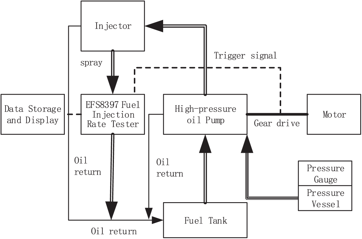
Figure 1: Spray test bench
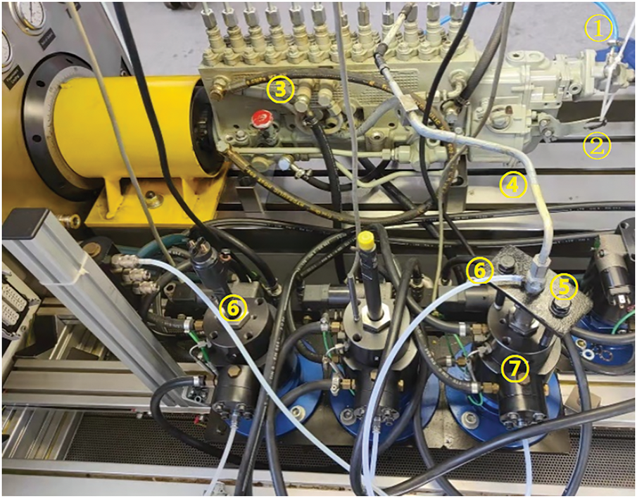
Figure 2: EFS8397 fuel injection pattern testing bench. ① Compressed air; ② Accelerator; ③ High-pressure oil pump of MTU183 diesel engine; ④ High-pressure oil pipe; ⑤ Injector; ⑥ Oil return pipe; ⑦ EFS8397 Fuel injection rate test
It is worth noting that the Compressed air tube connected in the test bench is not a simulation of the actual engine injection environment back pressure, but the actual engine intake pressure (boost pressure). Its function is to compensate the power of the governor rack movement when the engine runs at high speed.
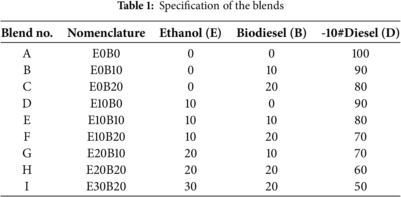
Based on the lubrication requirements of the diesel engine fuel system for blended fuels and the limited miscibility of ethanol and diesel at room temperature, this paper excludes the formulation with a high proportion of ethanol without adding biodiesel and determines nine blending ratios (by volume) of EBD fuels. Table 1 provides the detailed specification of the blends.
Based on the established test bench, injection characteristic tests of pure diesel were conducted at various speeds to analyze the impact of speed on fuel injection characteristics. On this basis, injection tests of EBD fuels with various blending ratios were carried out at the rated speed. Using pure diesel as the baseline, the effects of ethanol addition (with the proportion of biodiesel remaining constant) and biodiesel addition (with the proportion of ethanol remaining constant) on parameters such as the fuel injection quantity and injection rate of the blended fuels were analyzed.
2.3 Effect of Blended Fuel Ratios on Injection Quantity
Under different fuel-blend ratios, there are inevitable differences in the injection characteristics of the system. Even if the injection characteristics are consistent, variations in fuel density under different ratios can lead to changes in the injection quantity. Therefore, this study examined the impact of different fuel blend ratios on injection quantity at the same rotational speed (Compressed air pressure of 1 bar at 400 rpm, 1.3 bar at 600 rpm, 1.3 bar at 800 rpm, and 1.3 bar at 1025 rpm). This process provides a basis for calibrating the fuel supply during subsequent combustion tests. The injection quantities for the different fuel blend ratios are shown in Fig. 3.
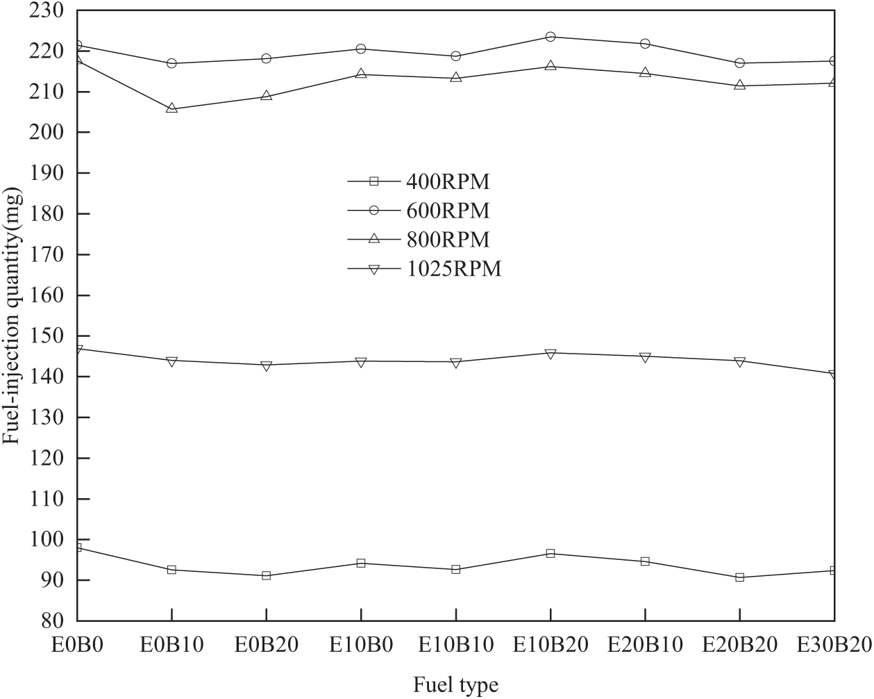
Figure 3: Comparison of fuel injection quantities for different fuel ratios at different speeds
Fig. 3 shows that the injection quantity of pure diesel at 1025 rpm of the high-pressure oil pump (air pressure of 1.3 bar) was 146.9 mg per injection (147 mg per injection according to the diesel engine manual). This indicates that the equipment used in this test (high-pressure oil pump and injector) are in good condition and the test results are reliable.
Additionally, the trend of injection quantity changes with fuel blend ratios was generally consistent at all rotational speeds, as depicted in Fig. 3. Pure diesel exhibited the highest injection quantity at all speeds, whereas the injection quantity of other blends decreased to varying degrees, which is due to the comprehensive influence of the physical properties of the three fuels, such as their density and viscosity. Under the same speed and ethanol blend ratio, the injection quantity first decreased and then increased with the addition of biodiesel. Under the same speed and biodiesel blend ratio, with the addition of ethanol, the injection quantity decreased when the biodiesel ratio was 0, remained relatively stable when the biodiesel ratio was 10%, and initially decreased and then increased when the biodiesel ratio was 20%. The effect of adding the same proportion of ethanol on the total injection quantity was greater than that of adding the same proportion of biodiesel.
With an increase in speed, the injection quantity first increased rapidly, then remained stable, and finally decreased significantly. This is because, at low speeds, the oil suction capacity of the pump is weak, and the component leakage time is longer. As the speed increases, the oil suction capacity of the pump strengthens rapidly, the component leakage time shortens, and the plunger volumetric efficiency increases significantly. When the speed increases further, the oil suction time of the pump decreases. After the pressure in the plunger chamber increases further, the leakage amount increases, causing the injection quantity to decrease.
It can be anticipated that with the addition of ethanol, the injection quantity decreases, requiring an increase in the effective oil supply stroke of the pump to increase the injection quantity. Additionally, because the calorific value of ethanol is low, a large proportion of ethanol may reduce the maximum power output of diesel engines. With the addition of biodiesel, the injection quantity increases slightly. Considering that the calorific value of biodiesel is lower than that of diesel in practical applications, it is necessary to increase the effective oil-supply stroke of the pump to increase the injection quantity.
2.4 Effect of Rotational Speed on Injection Rate
This study analyzed the effect of rotational speed on the injection rate, using pure diesel as an example. For convenience, the injection rates at different speeds were analyzed based on the falling edge of the missing tooth signal from the missing tooth disc provided by the fuel injection pump test bench (not the top dead center signal of the diesel engine cam). The details are shown in Fig. 4. In the figure, the vertical axis represents the injection rate in units of 1 kg/s, and the horizontal axis represents the crankshaft angle.
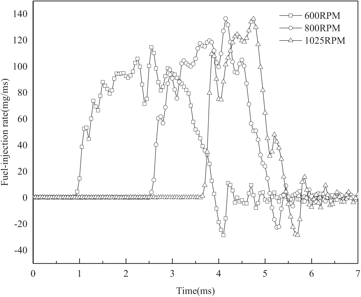
Figure 4: Effect of rotational speed on fuel injection rate
Fig. 4 illustrates the injection duration of 3.00 ms at 600 rpm, 2.60 ms at 800 rpm, and 1.90 ms at 1025 rpm. The injection duration first increased and then decreased with increasing speed. This is because, at lower speeds, as the speed increases, the volumetric efficiency of the high-pressure oil pump gradually increases, extending the oil supply time. At higher speeds, volumetric efficiency decreases owing to factors such as shorter intake time and increased leakage, resulting in a shorter oil supply time.
From 400 to 1025 rpm, the injection rate significantly increased with increasing speed, and the peak injection rate also increased with increasing speed. However, this increasing trend became less significant after 800 rpm.
Combining the injection duration and injection rate, from 400 to 1025 rpm, the injection quantity was the highest at 600 rpm, followed by 800 rpm, 1025 rpm, and the lowest at 400 rpm. This trend is consistent with the observations described in Section 3.
As the speed increased from 600 to 800 and 1025 rpm, the injection timing advance moved increasingly backward (by approximately 1–2°). This shortened the combustion preparation time, leading to an increase in post-combustion. However, the tested diesel engine was equipped with an automatic injection timing adjuster, which automatically increased the injection timing advance with increasing speed (with a maximum adjustment range of 10°) to ensure optimal injection timing and optimize in-cylinder combustion.
2.5 Effect of Ethanol Addition on Injection Rate
The variation in the injection rate with the ethanol addition ratio, while keeping the biodiesel addition ratio constant, is shown in Figs. 5–7.
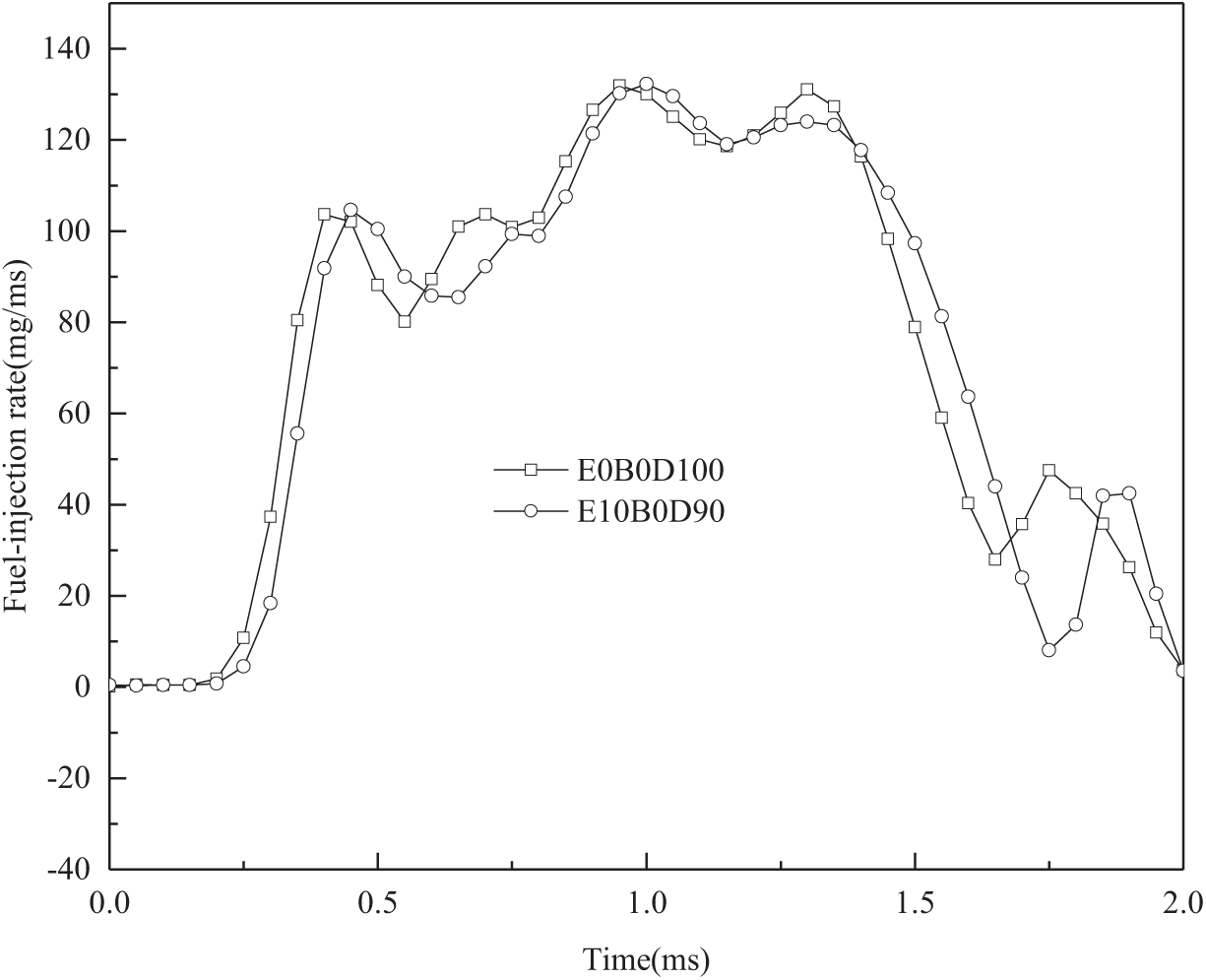
Figure 5: Injection rates of mixed fuels at different ethanol ratios with 0% biodiesel
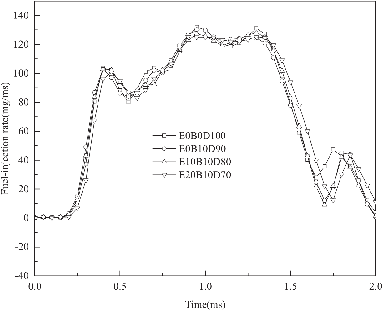
Figure 6: Injection rates of mixed fuels at different ethanol ratios with 10% biodiesel
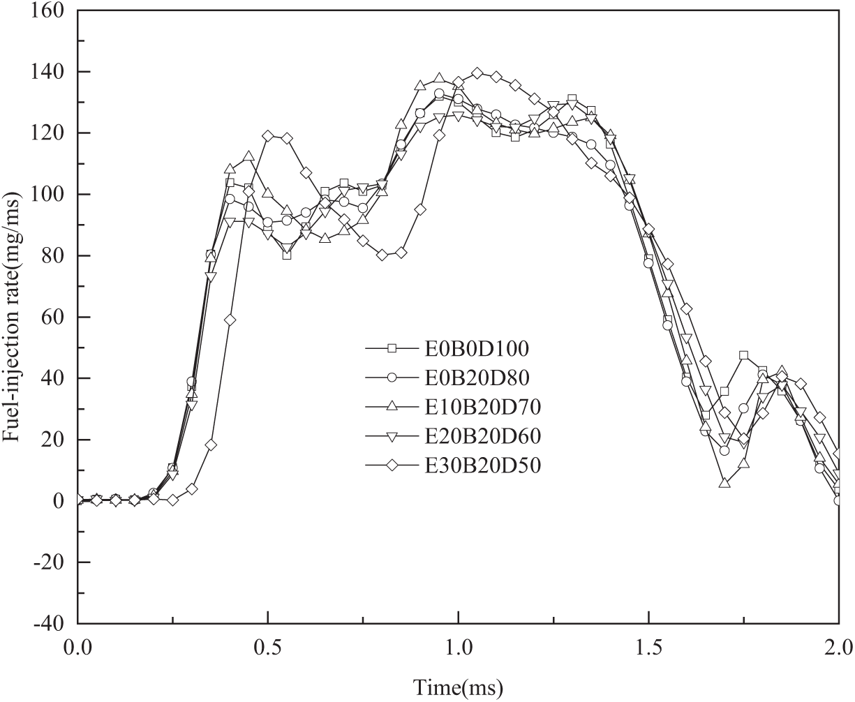
Figure 7: Injection rates of mixed fuels at different ethanol ratios with 20% biodiesel
After adding ethanol at the same rotational speed and other conditions (e.g., air pressure), the injection timing advance decreased. This is primarily because ethanol has a lower viscosity and higher leakage volume (Fig. 16), which causes a decrease in the volumetric efficiency of the pump and a rapid pressure drop at the nozzle end, further reducing the injection rate of ethanol. Additionally, the bulk modulus of elasticity of ethanol (922 N/mm2 at 20°C) is much smaller than that of diesel (1445 N/mm2 at 20°C) and biodiesel (1580 N/mm2 at 20°C), causing a delay in the injection timing advance and a lower injection rate after the addition of ethanol.
After adding 10% biodiesel, the injection rates of the various ethanol blend fuels at the same rotational speed and other conditions (e.g., air pressure) generally aligned well with that of pure diesel. However, significant deviations were observed in the peaks (including minor peaks and valleys). Additionally, the injection timing advances of all the blended fuels were slightly smaller than those of pure diesel, primarily because of the lower viscosity and higher leakage volume of ethanol, along with its lower modulus of elasticity and slower pressure build-up. In contrast, the effect of biodiesel at the same proportion on the injection timing advance was less than that of ethanol.
As shown in Fig. 7, after adding 20% biodiesel, the injection rates of the various fuel blends differed significantly, with the E30B20 fuel blend showing the most significant difference from the other fuels. This suggests that when the proportion of ethanol or the total proportion of ethanol and biodiesel is relatively high, it has a particularly significant impact on the injection rate. Therefore, when a diesel engine requires a high proportion of blended fuels containing ethanol or ethanol–biodiesel, the combustion characteristics of the engine may change considerably.
Overall, as illustrated in Figs. 5–7, when the total addition ratio of ethanol and biodiesel was relatively low, the injection rate of the blended fuel was similar to that of pure diesel. However, as the ethanol ratio increased, the differences in the injection rate curves of the blended fuel became more pronounced, particularly in the early and late stages of injection. Additionally, the influence of biodiesel on the injection rate and timing advance of the blended fuel was weaker than that of ethanol at the same ratio.
2.6 Effect of Biodiesel Addition on Injection Rate
The variation in the injection rate with the addition of biodiesel, while keeping the ethanol addition ratio constant, is shown in Figs. 8–10.
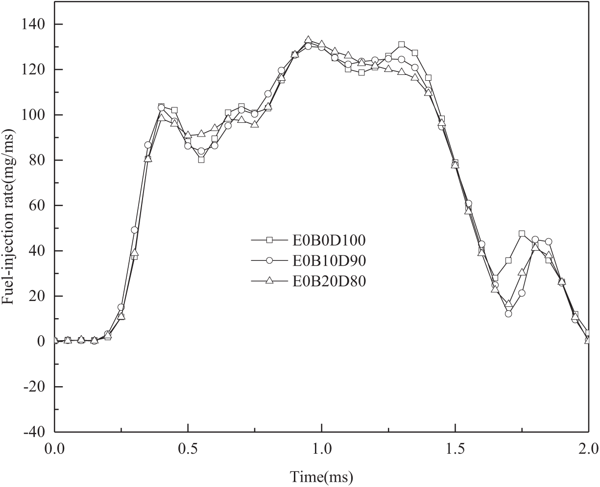
Figure 8: Injection rates of biodiesel at different ratios with 0% ethanol
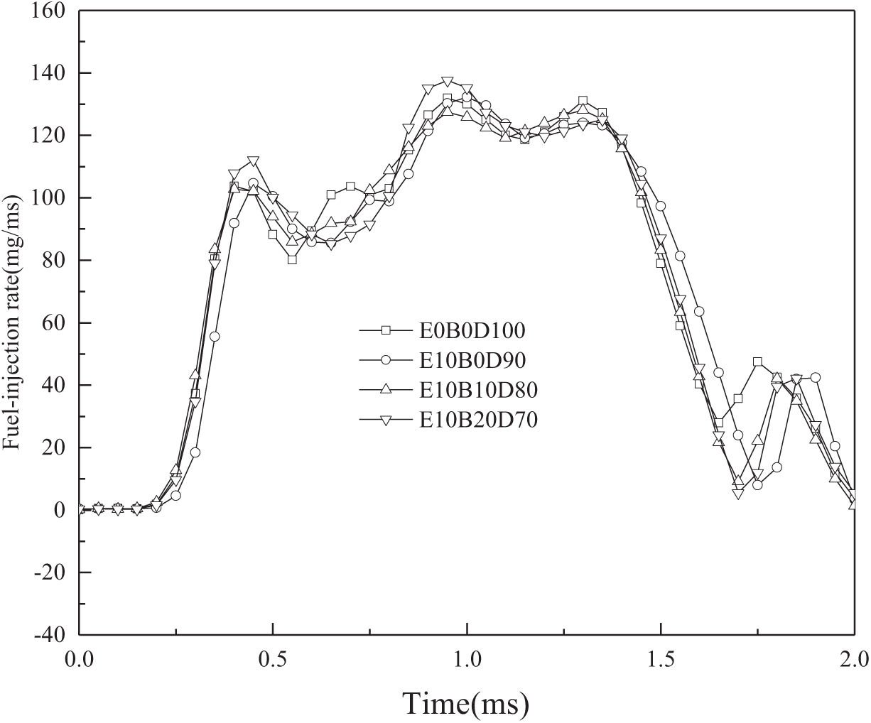
Figure 9: Injection rates of biodiesel at different ratios with 10% ethanol
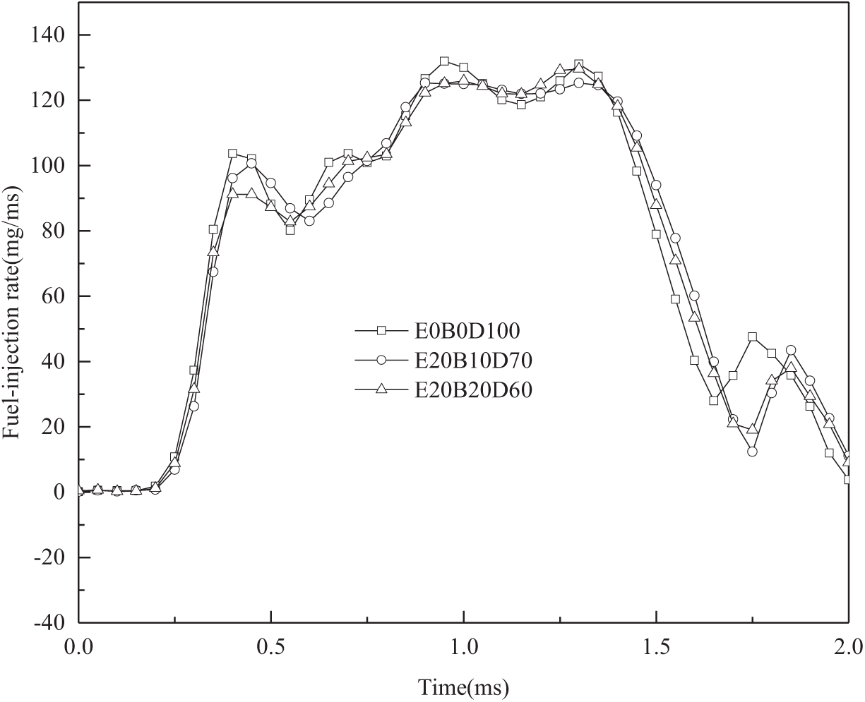
Figure 10: Injection rates of biodiesel at different ratios with 20% ethanol
Fig. 8 demonstrates that after adding biodiesel at the same rotational speed and under the same conditions (e.g., air pressure), the injection timing advance of the diesel engine decreased, and the injection duration shortened. After adding biodiesel at the same rotational speed and under the same conditions (e.g., air pressure), the peak injection rates decreased, and noticeable differences appeared in the later stages of injection (the descending part of the injection rate curve).
Overall, with the addition of 20% biodiesel, the injection rate curve of the blended fuel aligned well with that of pure diesel. Therefore, from the perspective of injection characteristics alone, adding a small to moderate amount of biodiesel (≤20%) is unlikely to significantly affect diesel engine combustion. However, considering that an excessively high total addition ratio may cause a large discrepancy between the injection rates of the blended fuel and diesel, it is advisable to maintain the biodiesel ratio within 20%.
From Fig. 9, it can be observed that after the addition of 10% ethanol, the injection rates of the various biodiesel blend fuels generally aligned well with the injection rates of pure diesel. However, noticeable differences were observed at the peaks (including minor peaks and valleys). Besides, after adding 10% ethanol, the injection timing advances of all the blended fuels were slightly smaller than those of pure diesel, mainly because ethanol has a lower viscosity and higher leakage volume, along with a lower modulus of elasticity and slower pressure build-up. In contrast, the effect of biodiesel at the same proportion on the injection timing advance was less significant than that of ethanol.
From Fig. 10, it can be observed that when the ethanol addition ratio increased to 20%, the consistency between the injection rate curves of the various blended fuels and pure diesel decreased compared with the case of a lower ethanol ratio. As shown in Figs. 9 and 10, when the ethanol addition ratios were 10% and 20%, respectively, the injection rate curves of several blended fuels significantly differed from those of pure diesel at the peaks and valleys. The injection timing advance of the 20% ethanol blend was generally smaller than that of the 10% ethanol blend. This indicates that biodiesel had a weaker effect on the injection rate and timing advance of the blended fuel than ethanol at the same proportion. These conclusions are consistent with the trends indicated by the simulation calculations.
In summary, the injection rate of a diesel engine changes significantly with the addition of ethanol or biodiesel. In particular, when a high proportion of ethanol or a high total addition ratio of ethanol and biodiesel is added, the injection rate shows considerable changes in terms of timing advance, duration, peak rate, and even the shape of the injection rate curve. Changes in injection characteristics inevitably lead to alterations in in-cylinder combustion, providing the possibility of optimizing diesel engine combustion and emissions.
3 Simulation Study on Injection Characteristics of Blended Fuels
3.1 Simulation Model Establishment
A simulation model was established based on the principles of the fuel injection system of a certain type of high-power marine diesel engine and the structural components of the high-pressure oil pump (including the cam, plunger, spring, inlet, and outlet oil ports) and injector (needle valve, spring, and nozzle), following reasonable physical abstraction. The simulation model is illustrated in Fig. 11.
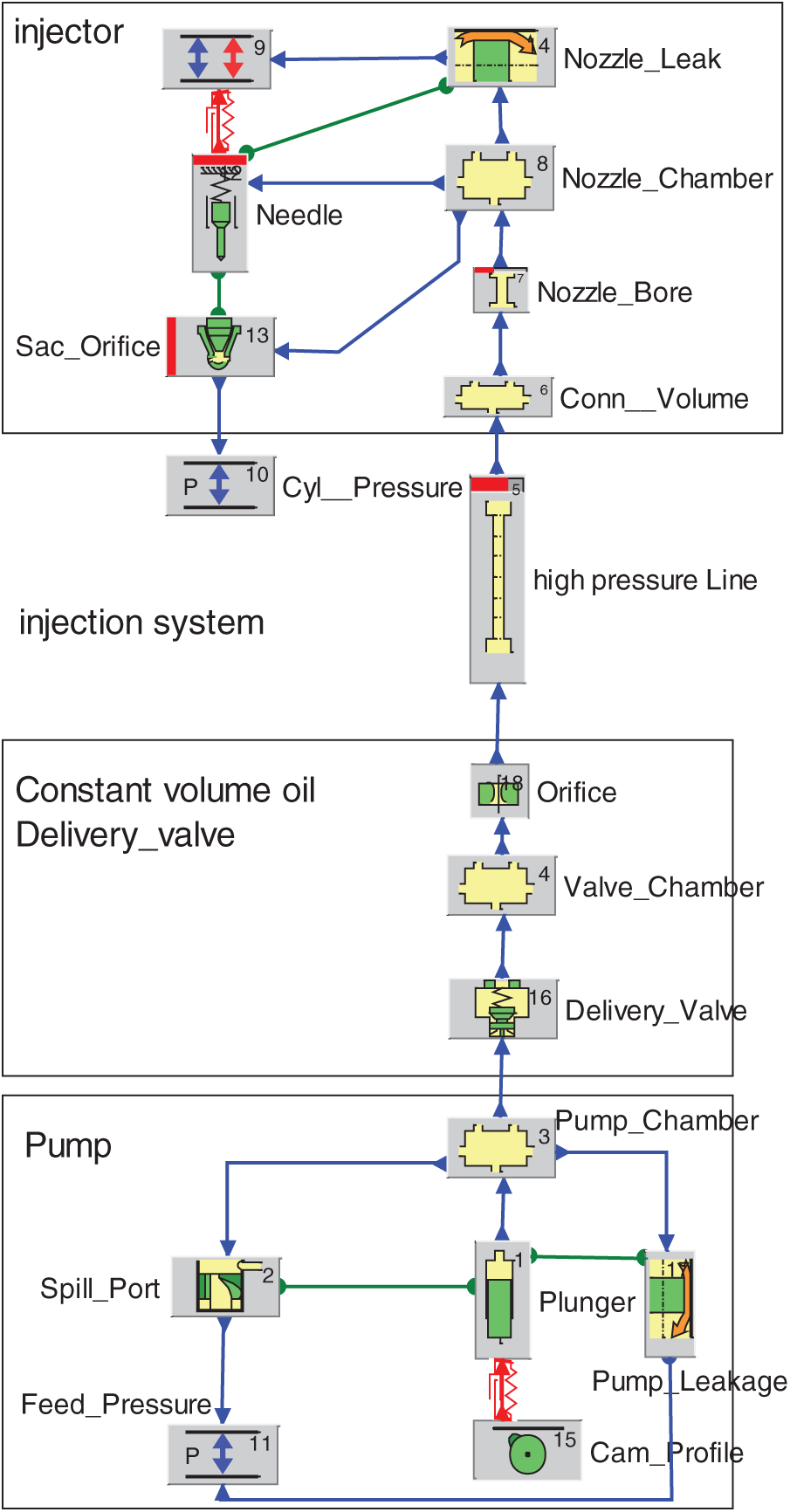
Figure 11: Fuel system simulation model
The parameter inputs for the unsteady state flow calculation model of the injection system were based on the actual system parameter values to ensure that the simulated results closely reflected the real pressure field within the injection system.
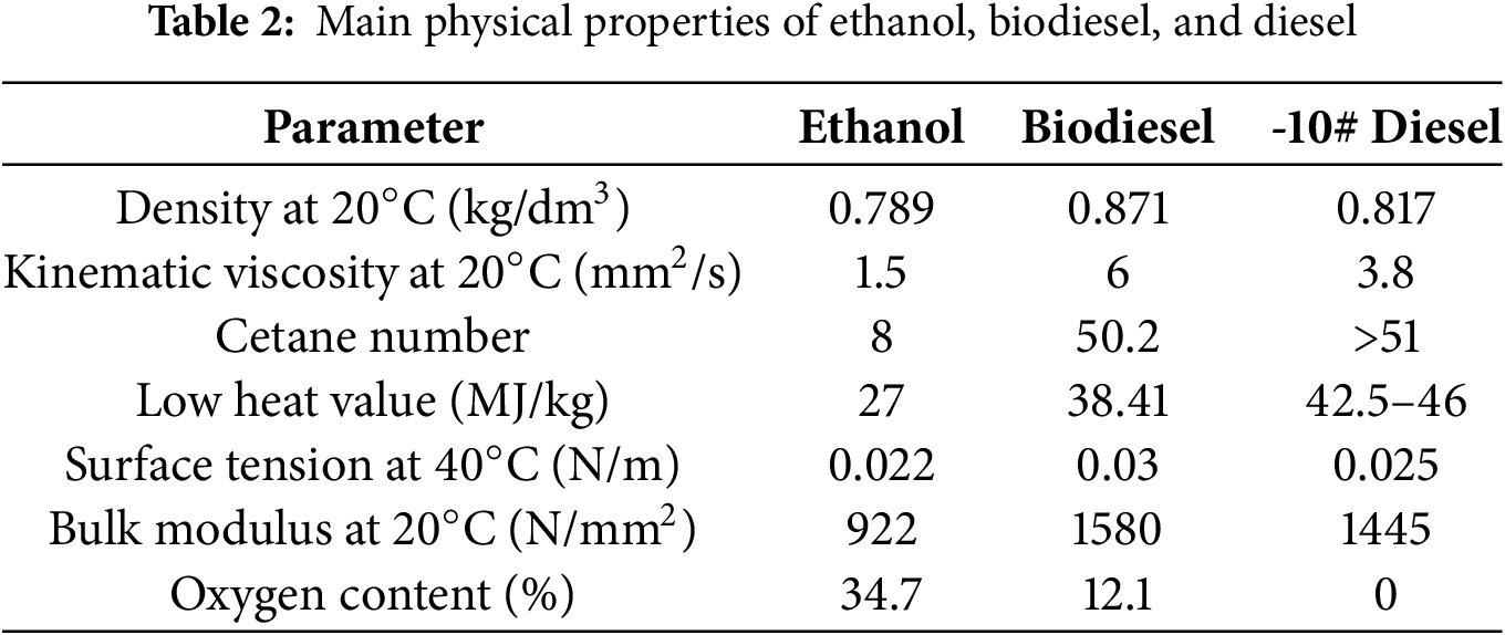
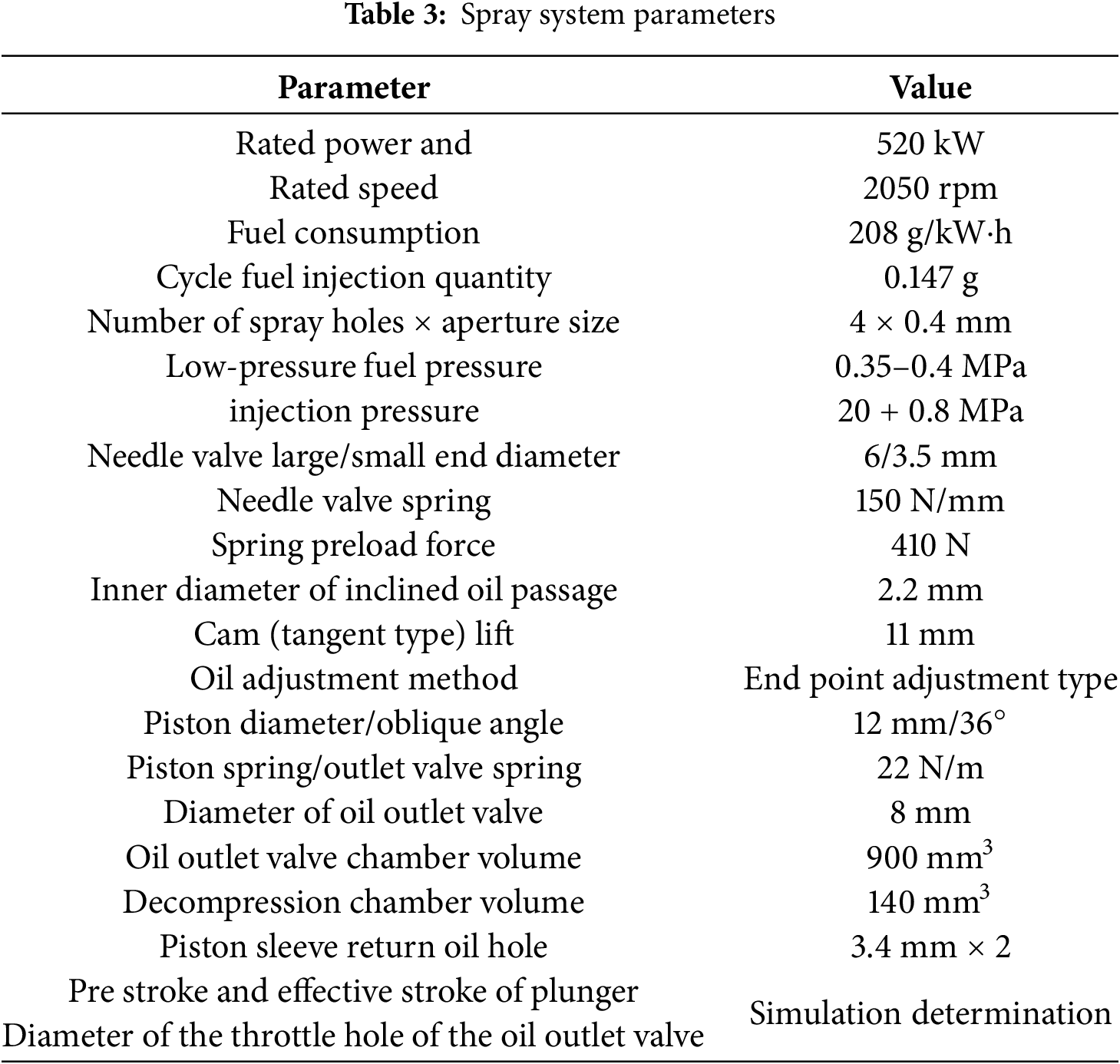
Table 2 lists the main physical and chemical properties of -10# diesel, ethanol, and biodiesel, and Table 3 lists the parameters of the diesel engine injection system.
3.2 Validation of the Simulation Model
Fuel injection rate tests were performed to verify the accuracy of the simulation model. A schematic of the test bench setup is shown in Fig. 4.
3.2.1 Validation of Injection Quantity
In the simulation, the fuel was set to standard diesel, and the diesel engine speed was set to 2050 rpm. The pre-stroke of the plunger was set to 7.5 mm and the effective stroke to 2.42 mm. The throttle-orifice diameter of the outlet valve was set to 0.8 mm (with the flow cross-sectional area of the throttle orifice equal to the total flow cross-sectional area of the injector nozzles). The cycle injection quantity was 147 mg under these conditions. In the experiment, -10# diesel was used, with the motor speed set to 1025 rpm. The high-pressure oil pump throttle position was maintained at the maximum, and the high-pressure pump was connected to an external air pressure of 1.3 bar (simulating the intake pipe pressure after the diesel engine intercooler). The measured injection quantity under these conditions was 146.9 mg.
3.2.2 Validation of Injection Rate
The simulated and measured injection rate curves are shown in Fig. 12.
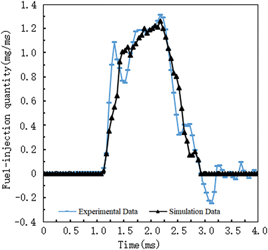
Figure 12: Comparison of the simulation and experimental fuel injection rates
As shown in Fig. 12, the shapes of the simulated and measured injection rate curves showed good agreement. For the same injection quantity, the simulated and measured injection durations were completely consistent. Both the simulated and measured injection rates exhibited an apparent decrease in the initial phase. However, the initial rise and fall amplitudes of the simulated injection rate were smaller. In the later phase of the injection, both the simulated and measured injection rates exhibited an increasing trend; however, the measured injection rate exhibited a sharper decline.
The high accuracy of the simulation model was confirmed through validation tests, making it suitable for simulating the injection characteristics of this type of diesel engine.
3.3 Effects of Fuel Properties on Injection Parameters
By maintaining the simulation parameters constant, the effects of different fuels (diesel, biodiesel, and ethanol) on the diesel engine injection parameters were analyzed. Comparisons of the Sauter mean diameter, spray cone angles, and penetration distances are shown in Figs. 13–15, respectively.
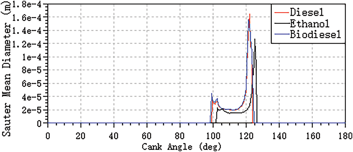
Figure 13: Comparison of the average Sauter mean diameter
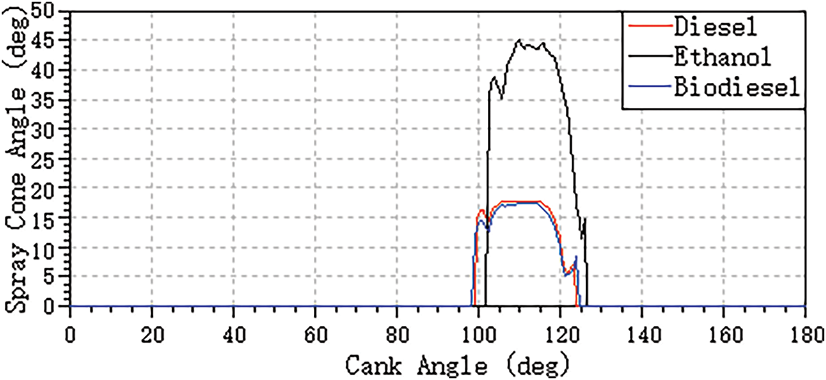
Figure 14: Comparison of spray cone angles
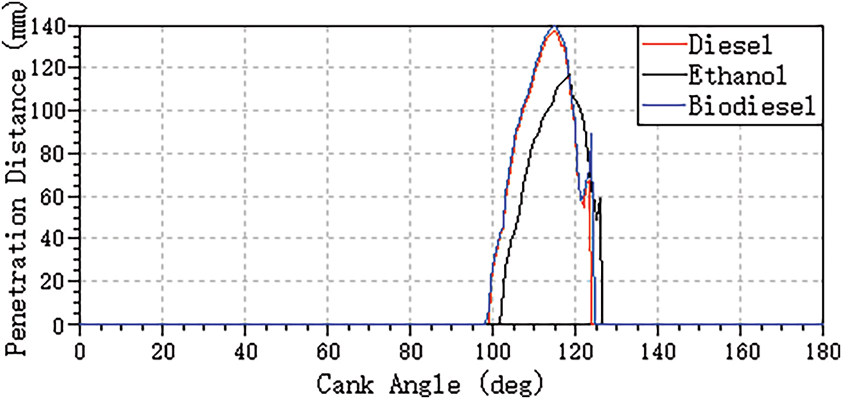
Figure 15: Comparison of penetration distances
As shown in Fig. 13, the Sauter mean diameter of biodiesel was slightly smaller than that of diesel, whereas the Sauter mean diameter of ethanol was significantly smaller than those of the other two fuels. This is mainly because ethanol has a lower kinematic viscosity (1.15 mm2/s at 20°C) and surface tension compared to biodiesel (5 mm2/s at 20°C) and diesel (3.8 mm2/s at 20°C). The weaker intermolecular forces in ethanol render the particles more prone to breaking and evaporation, leading to a reduction in the Sauter mean diameter. Thus, adding ethanol is beneficial for improving spray atomization.
As shown in Fig. 14, the spray cone angle of biodiesel was slightly smaller than that of diesel, whereas the spray cone angle of ethanol was significantly larger than those of the other two fuels. This is mainly due to the lower viscosity and density of ethanol.
From Fig. 15, it can be observed that the spray penetration distance of biodiesel was slightly greater than that of diesel in the early stage of injection because of the higher injection rate; however, they overlapped later as their injection rates converged. The spray penetration distance of ethanol was significantly shorter than that of the other two. This is primarily because compared with biodiesel and diesel, ethanol has a lower density and flow resistance coefficient combined with a much lower injection quantity and injection rate.
Overall, as shown in Figs. 13–15, the effect of adding the same proportion of ethanol on the injection parameters of the diesel engine was greater than that of adding the same proportion of biodiesel.
3.4 Effects of Fuel Properties on Component Leakage
Viscosity is the property of a fluid that manifests as internal frictional resistance to the relative motion between fluid molecules during flow. At the same working pressure, excessively high viscosity increases the motion resistance of various components, accelerates temperature increase, reduces the self-priming ability of the pump, and increases pressure drop in the pipelines and power loss. Conversely, an excessively low viscosity increases the volumetric loss of the pump and reduces the supporting force of the oil film, potentially causing dry friction between the friction pairs. Therefore, under the given operating conditions, the blended fuels must have an appropriate viscosity range for the fuel-injection system. Typically, the leakage volume and shear stress on the clearance components can be calculated using the following equations [20]:
where the first term in Eq. (1) represents the value generated due to the pressure difference, and the second term represents the value generated due to relative motion between the components; Q is the leakage volume; Lgap is the sealing length of the component; Rp and Rb are the radii of the plunger and the pump body, respectively; Pin and Pout are the fuel pressures in the chamber and the return chamber; Vb is the pump body motion speed (0 m/s); Vp is the plunger motion speed; μ is the dynamic viscosity of the fluid; Fshear_p is the viscous shear stress on the plunger.
Eqs. (1) and (2) show that the leakage volume in the clearance is negatively correlated with the fuel viscosity, whereas the shear stress on the components is positively correlated with the fuel viscosity.
By maintaining the simulation parameters constant, changing the fuel type (altering the physical properties of the fuel) alters the component clearance leakage volume, as shown in Fig. 16.
As shown in Fig. 16, the leakage volume increased as fuel viscosity decreased. For instance, the component leakage volume when using ethanol was approximately 2.5 times higher than when using diesel, while the component leakage volume when using biodiesel was similar to that using diesel. In other words, the volumetric efficiency of the high-pressure oil pump decreased with decreasing fuel viscosity.

Figure 16: Comparison of fuel leakages during plunger coupling
It can be observed from Fig. 17 that the shear force on the plunger decreased as fuel viscosity decreased. The shear force on the plunger when using ethanol was approximately one-third of that with diesel, while the shear force when using biodiesel was nearly the same as with diesel. To prevent adhesive wear, abrasive wear, and other performance degradation under the high-speed operating conditions of the high-pressure oil pump, it is essential to ensure proper lubrication by maintaining an appropriate fuel viscosity. Therefore, the ethanol mixing ratio in blended fuels should not be too high.
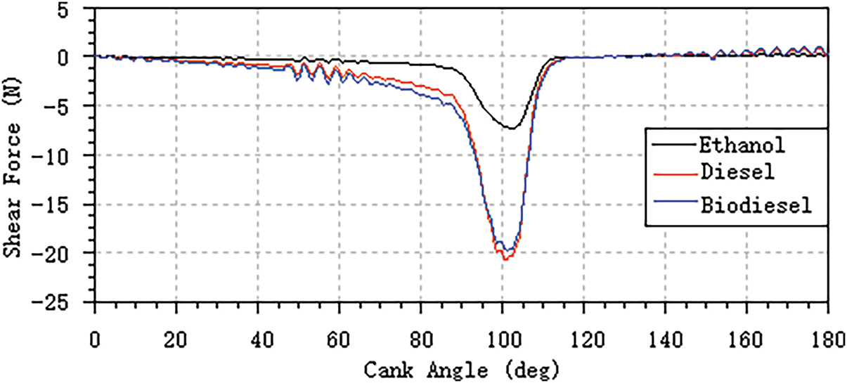
Figure 17: Comparison of shear forces on the piston
This study investigated the effects of ethanol-biodiesel-diesel blend ratios on the fuel injection quantity and injection rate in diesel engines through experimental research. Additionally, simulations were conducted to study the effects of these blend ratios on diesel engine spray characteristics. The findings are summarized as follows:
(1) The blending of biodiesel and ethanol affected all injection characteristic parameters, with ethanol having a stronger impact on the injection characteristics of the blended fuel than biodiesel.
(2) With the addition of ethanol, the viscosity of the blended fuel decreased. While the changes in the penetration distance and Sauter mean diameter were minimal, the spray cone angle increased significantly. This may deteriorate the matching characteristics of the “fuel-air-chamber” in the original engine. Considering the cetane number and other comprehensive parameters of ethanol, the ethanol blending ratio should not exceed 30%.
(3) As the biodiesel content increased, the viscosity of the blended fuel increased. The changes in the penetration distance and spray cone angle were insignificant, whereas the Sauter mean diameter increased slightly. The matching characteristics of the “fuel-air-chamber” of the diesel engine did not change significantly, but the fuel atomization quality deteriorated slightly.
(4) As the ethanol blending ratio increased, the leakage volume of the fuel system components increased significantly. To ensure proper lubrication of the fuel system components, the ethanol blending ratio in the mixed fuel should not be excessively high.
In summary, a high proportion of ethanol is not recommended when blended fuels are used in diesel engines. Furthermore, it is necessary to add an appropriate amount of biodiesel to ensure good miscibility between ethanol and diesel and to ensure that the viscosity and other physical properties of the blended fuel are roughly equivalent to those of diesel. The biodiesel addition ratio should not exceed 20% or that of ethanol. The addition of an appropriate amount of biodiesel helps maintain good spray characteristics and lubrication properties comparable to diesel, ensuring good atomization and “fuel-air-chamber” matching.
Acknowledgement: None.
Funding Statement: This work is supported by Innovation Research Project for the training of high-level scientific and technological talents (Technical expert talents) of the Armed Police Force ZZKY20222415, “13th Five-Year Plan” military key colleges and key disciplines-Equipment Engineering (Power)-17.
Author Contributions: The authors confirm contribution to the paper as follows: study conception and design: Hailong Chen, Yu Zhang; data collection: Hailong Chen, Yu Zhang; analysis and interpretation of results: Hailong Chen, Mingyu Zhang, Xin Luan; draft manuscript preparation: Hailong Chen, Yu Zhang, Guanzhen Tao. All authors reviewed the results and approved the final version of the manuscript.
Availability of Data and Materials: The datasets generated and/or analyzed during the current study are available from the corresponding author on reasonable request.
Ethics Approval: Not applicable.
Conflicts of Interest: The authors declare no conflicts of interest to report regarding the present study.
References
1. Rao YH, Voleti RS, Hariharan VS, Raju AS, Redd PN. Use of Jatropha oil ME and its blends as an alternative fuel in diesel engine. J Braz Soc Mech Sci Eng. 2009;31(3):253–60. doi:10.1590/S1678-58782009000300011. [Google Scholar] [CrossRef]
2. Raman R, Narayanan G, Manoharan N, Sendilvelan S. Experimentation on emission analysis of a compression ignition engine run with biodiesel. Rasayan J Chem. 2017;10:944–51. doi:10.7324/RJC.2017.1031664. [Google Scholar] [CrossRef]
3. Chen Y, Aa A, Abed AM, Nasajpour-Esfahani N, Smaisim GF, Hadrawi SK, et al. The combustion process of methyl ester-biodiesel in the presence of different nanoparticles: a molecular dynamics approach. J Mol Liq. 2023;373(9):121232. doi:10.1016/j.molliq.2023.121232. [Google Scholar] [CrossRef]
4. Yin Z, Zhu L, Li S, Hu T, Chu R, Mo F, et al. A comprehensive review on cultivation and harvesting of microalgae for biodiesel production: environmental pollution control and future directions. Bioresour Technol. 2020;301(6):122804. doi:10.1016/J.BIORTECH.2020.122804. [Google Scholar] [PubMed] [CrossRef]
5. Gaur A, Dwivedi G, Baredar P, Jain S. Influence of blending additives in biodiesel on physiochemical properties, engine performance, and emission characteristics. Fuel. 2022;321(1):124072. doi:10.1016/j.fuel.2022.124072. [Google Scholar] [CrossRef]
6. Shanker Yadav P, Said Z, Gautam R, Caliskan H, Wu H. Impact of hydrogen induction on atomization combustion performance and emissions in diesel engines fueled with heated biodiesel blends. Energy. 2024;313(14):134026. doi:10.1016/j.energy.2024.134026. [Google Scholar] [CrossRef]
7. Hazar H, Sevinc H, Sap S. Performance and emission properties of preheated and blended fennel vegetable oil in a coated diesel engine. Fuel. 2019;254(2):115677. doi:10.1016/j.fuel.2019.115677. [Google Scholar] [CrossRef]
8. Abed KA, Gad MS, El Morsi AK, Sayed MM, Elyazeed SA. Effect of biodiesel fuels on diesel engine emissions. Egypt J Pet. 2019;28(2):183–8. doi:10.1016/j.ejpe.2019.03.001. [Google Scholar] [CrossRef]
9. Estevez R, López-Tenllado FJ, Montes V, Romero AA, Bautista FM, Luna D. Characterization of several 2-ethylhexyl nitrates with vegetable oil (Castor or Sunflower Oil) blends in triple blends with diesel, working as advanced biofuels in C.I. Diesel Engines. Appl Sci. 2024;14(24):11968. doi:10.3390/app142411968. [Google Scholar] [CrossRef]
10. Bitire SO, Jen T-C. The role of a novel green synthesized nanoparticles added parsley biodiesel blend on the performance-emission characteristics of a diesel engine. S Afr J Chem Eng. 2022;41(6):161–75. doi:10.1016/j.sajce.2022.06.007. [Google Scholar] [CrossRef]
11. Wai P, Kanokkhanarat P, Oh BS, Wongpattharaworakul V, Depaiwa N, Po-ngaen W, et al. Experimental investigation of the influence of ethanol and biodiesel on common rail direct injection diesel Engine’s combustion and emission characteristics. Case Stud Therm Eng. 2022;39:102430. doi:10.1016/J.CSITE.2022.102430. [Google Scholar] [CrossRef]
12. Shirneshan A, Bagherzadeh SA, Najafi G, Mamat R, Mazlan M. Optimization and investigation the effects of using biodiesel-ethanol blends on the performance and emission characteristics of a diesel engine by genetic algorithm. Fuel. 2021;289(1):119753. doi:10.1016/j.fuel.2020.119753. [Google Scholar] [CrossRef]
13. Bhurat SS, Pasupuleti SR, Kunwer R, Gugulothu SK, Joshi SK. Effect of ethanol-diesel blend on compression ignition engine: a mini review. Mater Today Proc. 2022;69(1):459–62. doi:10.1016/j.matpr.2022.09.139. [Google Scholar] [CrossRef]
14. Santos NDSA, Roso VR, Malaquias ACT, Baeta JGC. Internal combustion engines and biofuels: examining why this robust combination should not be ignored for future sustainable transportation. Renew Sustain Energy Rev. 2021;148:111292. doi:10.1016/j.rser.2021.111292. [Google Scholar] [CrossRef]
15. El-Nagar AA, El-Sheekh MM, Elkelawy M, Bastawissi HAE. Enhancing diesel engine performance and emissions with innovative Ethanol-Surfactant blends in Biodiesel: unveiling insights through fractional factorial design. Sustain Energy Technol Assess. 2025;73:104169. doi:10.1016/j.seta.2024.104169. [Google Scholar] [CrossRef]
16. Kannan D, Pachamuthu S, Md Nurun N, Hustad JE, Løvås T. Theoretical and experimental investigation of diesel engine performance, combustion and emissions analysis fuelled with the blends of ethanol, diesel and jatropha methyl ester. Energy Convers Manag. 2012;53(1):322–31. doi:10.1016/j.enconman.2011.09.010. [Google Scholar] [CrossRef]
17. Shahir SA, Masjuki HH, Kalam MA, Imran A, Fattah IMR, Sanjid A. Feasibility of diesel-biodiesel–ethanol/bioethanol blend as existing CI engine fuel: an assessment of properties, material compatibility, safety and combustion. Renew Sustain Energy Rev. 2014;32:379–95. doi:10.1016/j.rser.2014.01.029. [Google Scholar] [CrossRef]
18. Sathish T, Mohanavel V, Arunkumar M, Rajan K, Soudagar MEM, Mujtaba MA, et al. Utilization of Azadirachta indica biodiesel, ethanol and diesel blends for diesel engine applications with engine emission profile. Fuel. 2022;319(2):123798. doi:10.1016/j.fuel.2022.123798. [Google Scholar] [CrossRef]
19. Silitonga AS, Masjuki HH, Ong HC, Sebayang AH, Dharma S, Kusumo F, et al. Evaluation of the engine performance and exhaust emissions of biodiesel-bioethanol-diesel blends using kernel-based extreme learning machine. Energy. 2018;159(10):1075–87. doi:10.1016/j.energy.2018.06.202. [Google Scholar] [CrossRef]
20. AVL List GmbH. AVL-Hydsim Users Guider [Internet]. [cited 2025 Apr 9]. Available from: http://www.avl.com. [Google Scholar]
Cite This Article
 Copyright © 2025 The Author(s). Published by Tech Science Press.
This work is licensed under a Creative Commons Attribution 4.0 International License , which permits unrestricted use, distribution, and reproduction in any medium, provided the original work is properly cited.
 Downloads
 Citation Tools