
 Submit a Paper
 Propose a Special lssue
 Open Access
ARTICLE

CFD-Based Optimization of Aerodynamic Noise in High-Speed Hair Dryer Flow Channels
1 College of Mechanical Electronical and Engineering, Zhuhai City Polytechnic, Zhuhai, 519000, China
2 Technology Department, Kretech Tech (Dongguan) Co., Ltd., Dongguan, 523000, China
3 Design Department, Guangdong Vastron Technology Co., Ltd., Foshan, 528225, China
* Corresponding Authors: Ya Li. Email: ,
(This article belongs to the Special Issue: Fluid Mechanics & Thermodynamics in Renewable Energy and HVAC Systems)
Fluid Dynamics & Materials Processing 2025, 21(7), 1611-1622. https://doi.org/10.32604/fdmp.2025.067497
Received 05 May 2025; Accepted 03 July 2025; Issue published 31 July 2025
 View Full Text
 Download PDF
Abstract
The noise generated by high-speed hair dryers significantly affects user experience, with aerodynamic design playing a crucial role in controlling sound emissions. This study investigates the aerodynamic noise characteristics of a commercial high-speed hair dryer through Computational Fluid Dynamics (CFD) analysis. The velocity field, streamline patterns, and vector distribution within the primary flow path and internal cavity were systematically examined. Results indicate that strong interactions between the wake flow generated by the guide vanes and the straight baffle in the rear flow path induce vortex structures near the outlet, which are primarily responsible for high-frequency noise. To address this, the guide vanes and rear flow path geometry were redesigned and optimized for improved acoustic and aerodynamic performance. Underrated operating conditions (28 V, 20,000 rpm), the optimized configuration achieves a noise reduction of more than 2.2 dB while increasing outlet wind speed by over 9%. Moreover, the noise suppression effect becomes more pronounced at lower rotational speeds.Keywords
With the continuous improvement of the quality of life, consumers have put forward higher requirements for the noise performance of household appliances. As a small household appliance that is used frequently, the noise level of hair dryer directly affects the user experience. Studies have shown that the noise of hair dryers is mainly composed of motor vibration and aerodynamic noise, of which aerodynamic noise accounts for more than 60% [1]. When high-velocity airflow flows through complex flow channels, broadband noise caused by flow separation, vortex shedding, and turbulent pulsation is particularly significant [2]. In recent years, some progress has been made in the optimization of aerodynamic noise in the fields of centrifugal fans and axial fans. For example, the bionic airfoil blade design reduces centrifugal fan noise by 3–5 dB [3], and the spiral volute structure effectively suppresses eddy vortex noise [4]. However, there is still a lack of research on aerodynamic noise in small high-speed runner systems such as hair dryers, especially the coupling mechanism between flow field and noise is still unclear [5]. Noise prediction is one of the main research directions in the field of aerodynamic noise research, and with the development of research methods, the research of noise prediction methods has entered a new field.
Traditional noise reduction methods rely on experimental testing and empirical judgment, but they are limited by the cost and resolution of the test, and it is difficult to capture the microscopic characteristics of the flow field [6]. The development of Computational Fluid Dynamics (CFD) technology provides a new way for the refined analysis of flow fields. The results show that the k-ε model combined with Large Eddy Simulation (LES) can effectively predict the spectral characteristics of turbulent noise, while the Ffowcs Williams-Hawkings (FW-H) acoustic analogy method can quantify the contribution of dipole and quadrupole sound sources in the flow field [7,8]. In terms of experimental research, the hemi-anechoic chamber and sound pressure array technology provide a high-precision means for the location of noise sources. However, most of the existing studies focus on large-scale fan systems, and there is a lack of systematic discussion on the optimization of flow channels for small equipment such as hair dryers [9,10]. The design of the guide impeller and rear runner is the key to aerodynamic noise optimization. Studies have shown that the optimization of the leading edge inclination angle of the guide impeller can reduce the flow separation loss, and the optimization of the curvature of the rear flow channel can reduce the turbulent intensity by up to 15% [11,12]. In addition, the Aerodynamic Approach shows potential in the co-design of impeller geometry [13–15]. However, the compactness and high speed of the hair dryer flow channel lead to a significant difference in flow characteristics from that of large equipment. For example, the flow velocity at the outlet of the hair dryer often exceeds 20 m/s, and the Reynolds number in the flow channel is as high as 105, which is easy to induce high-frequency eddy current noise. The existing studies have not yet formed a unified theoretical model for the noise generation mechanism of this kind of high Reynolds number flow. At present, the main methods of noise prediction: 1. A purely theoretical approach; 2. Computational Fluid Dynamics (CFD) and Computational Aeroacoustics (CAA) methods; 3. Semi-empirical approach; 4. Purely numerical methods [16,17]. Computational Aeroacoustics (CAA) is a numerical simulation method that combines Computational Fluid Dynamics (CFD) and acoustic theory to predict and analyze the generation and propagation of flow noise. In hair dryer design, the CAA model is widely used to optimize the air duct structure, impeller design, and airflow organization to reduce aerodynamic noise and improve user experience [18,19]. Compared with traditional experimental testing, CAA technology can predict noise characteristics in the early stage of product development, greatly shortening the development cycle and reducing costs [20].
In this study, we systematically explored the mechanism of aerodynamic noise in the flow channel of a household appliance blowing air by combining CFD simulation and experimental tests. By constructing a three-dimensional runner model, the steady-state results of the k-ε turbulence model are used to calculate the internal flow characteristics and the Large-Eddy Simulation (LES) model combined with the transient slip grid technology to simulate the internal flow characteristics, and the influence of the interference between the wake of the guide impeller and the rear runner on the noise spectrum is revealed. On this basis, a runner optimization scheme based on NACA airfoil combined with spiral deflector was proposed, and its noise reduction effect was verified by experiments. The purpose of this study is to provide theoretical support for the low-noise design of hair dryers in the home appliance industry and to fill the gap in the research on aerodynamic noise of small high-speed runner systems.
The noise test experiment is based on GB/T4214.6 and GB/T4214.1 Chapter 7 test sample upgrade level test. The test is carried out by adjusting the voltage, and the voltage gear is set to 16, 20, 22, 24, 26, 28, and 30 V, respectively. The whole test process is carried out in a silent box, using the hemispherical test method, and the test device is shown in Fig. 1. The wind speed test experiment is to measure the wind speed by placing the anemometer 10 cm in front of the hair dryer outlet, and Fig. 1d is the C-MER AS856 anemometer.
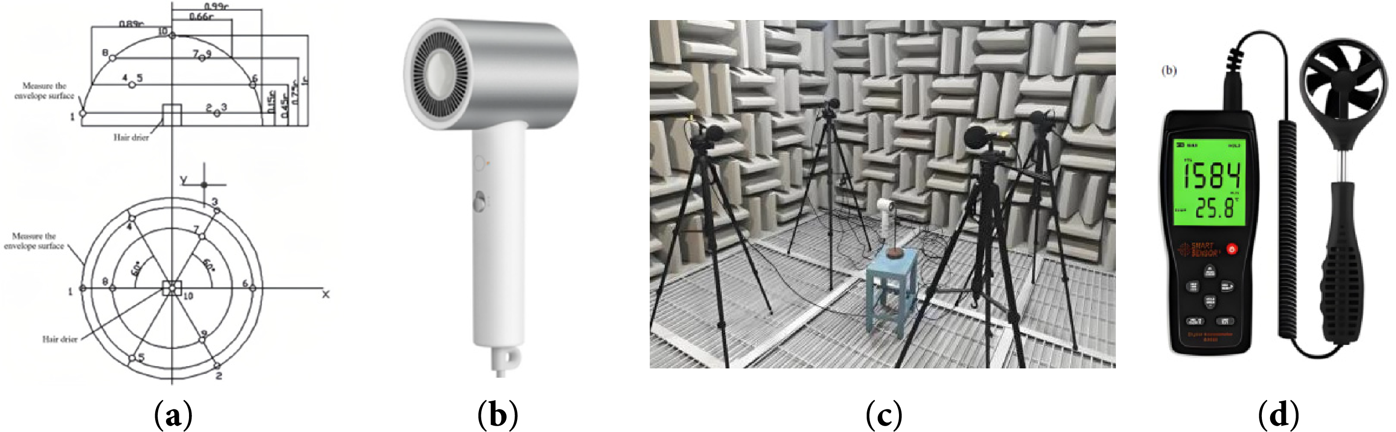
Figure 1: Hair dryer test. (a) Test location diagram; (b) Hair dryer; (c) Experimental test; (d) Anemometer
Test environment: ambient temperature: 20°C~23°C, ambient humidity: 48% RH.
Test conditions:
(1) Hot air II gear, the machine reaches a stable state after 2 min of operation;
(2) Noise test layout: R = 1 m hemispherical arrangement of multiple radio devices;
(3) Wind speed test layout: Place an anemometer 10 cm in front of the air outlet.
According to the general standards of the industry, the original hair dryer was tested in detail, focusing on its wind speed and noise level. According to the current industry standard, the noise level of the hair dryer should be controlled below 75 dB to ensure that it will not have a significant negative impact on the user’s hearing health and user experience during normal use. As shown in Table 1, the noise and wind speed increase as the voltage (rotational speed) increases. Experimental test results showed that the noise level of the original hair dryer reached 79.8 dB, which significantly exceeded the industry standard limit of 75 dB. This indicates that the current noise control situation of hair dryers has not yet met the requirements of industry standards, and its design still needs to be further optimized to reduce noise levels and improve the overall performance and user experience of the product.
The FW-H equation of Fluent software is used to integrate far-field sound propagation and sound radiation. The turbulence model of Reynolds averaged method adopts standard
The gas flow of a hair dryer belongs to: steady-state three-dimensional non-compressible flow, so the equation for the conservation of mass can be simplified as:
Since air is a Newtonian fluid, the equation for the conservation of momentum can be simplified as:
Since the influence of the impeller on the fluid flow is not considered at the beginning of the hair dryer simulation, there is no strong swirl in the whole flow process, and the standard
In the standard
In LES model, large eddies are resolved directly, while small eddies are modeled. Filtering the time-dependent Navier-Stokes equations in either wave-number space or physical space can get the governing equations employed for LES [22,23].
The unsteady filtered mass continuity equation is:
The filtered incompressible unsteady three-dimensional Navier-Stokes equations are:
where
In the Smagorinsky-Lilly model, the eddy-viscosity is modeled by:
where
The Ffowcs-Williams and Hawkings (FW-H) equation is essentially an inhomogeneous wave equation that can be derived by manipulating the continuity equation and the Navier-Stokes equations. This formulation has been successfully used for helicopter rotor and propeller noise predictions [24].
In the formula:
3.2 Mesh Models and Boundary Conditions
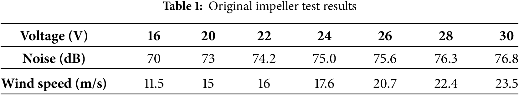
This model has conducted a detailed physical modeling for a certain hair dryer, and its flow channel module is shown in Fig. 2. In order to improve the efficiency of aerodynamic noise calculation and ensure the pertinence of the research, this study simplified the model by removing non critical components such as the housing and handle, and only retaining the core structure of the flow channel system, including the impeller, guide impeller, and rear flow channel.
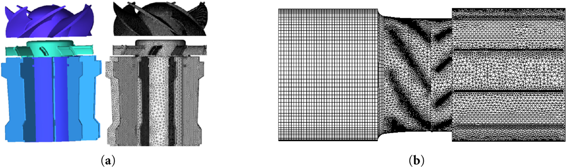
Figure 2: Hair dryer. (a) Impeller and guide grid; (b) Flow channel grid; (c) Overall regional grid; (d) Wall plus (Y+) distribution
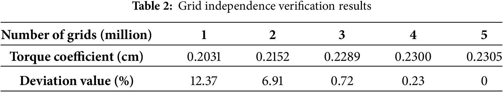
In CFD simulations, grid independence is usually confirmed by monitoring changes in certain key parameters, and the torque coefficient Cm is one of the commonly used characterization indicators for rotating machinery. This simulation conducted simulations with 5 sets of grid quantities, including 1 million, 2 million, 3 million, 4 million, 10 million, and 5 million. The specific results are shown in Table 2. When the number of grids is 1 million and 2 million, the torque coefficients Cm calculated are 0.2031 and 0.2152, respectively, with deviations of 12.37% and 6.91%. When the number of grids reaches 3 million, the value of torque coefficient Cm is 0.2289, with a deviation value of 0.72%. And when the number of grids continues to increase to 4 million and 5 million, the change in Cm value is very small, with a deviation value of 0.23% for 4 million grids. It can be concluded that the grid independence has been verified, and configuring 3 million grids is appropriate. The mesh model of the hair dryer calculation area is shown in Fig. 2a–c.
In addition, in CFD, the Y+ value is a dimensionless numerical value that describes the resolution of the boundary layer mesh and is typically used to evaluate the degree of mesh refinement near the wall. The selection of Y+ value is crucial for the accuracy of the results based on the characteristics, flow state, and simulation requirements of the fluid. To ensure accuracy under dynamic loads and complex flow conditions, especially at high speeds where fluid velocities are high and the boundary layer develops rapidly. When conducting grid convergence research and boundary layer resolution analysis this time, the boundary layer thickness was 0.001 mm, and the impeller Y+ < 2, ensuring that the Y+ value between 1 and 5 is a suitable choice, as shown in Fig. 2d. This can effectively capture the characteristics of the boundary layer and improve the accuracy of the calculation results.
In this study, Computational Fluid Dynamics (CFD) was used to numerically simulate its internal flow characteristics. The mesh file of the simplified physical model of the hair dryer generated by ICEM was imported into the fluid simulation software FLUENT with the following boundary conditions:
(1) Rotation domain processing: The slip mesh model is adopted, and the impeller area is set to the rotation domain, and the rotation speed is 20,000 revolutions per minute.
(2) Boundary conditions:
–Inlet: Pressure Inlet, total pressure set to atmospheric pressure (101,325 Pa);
– Outlet: Pressure Outlet, static pressure is the ambient pressure;
– Fluid domain: The impeller area, volute area and air duct area are all defined as the fluid zone, with an air density of 1.225 kg/m3 and a dynamic viscosity of 1.789 × 10⁻⁵ Pa·s;
– Time step size: The blade rotation angle method is usually used to define the time step, and it is recommended to rotate the blade by 1 degree at each time step. The blade rotation period is 0.003 s, so a calculation time step of 1 × 10⁻⁵ s is sufficient.
(3)Solver and discrete format: The standard interpolation scheme was used to compute the face value of the pressure for a controlled volume. The SIMPLEC algorithm was used to adjust the velocity fields by correcting the pressure fields in pressure-velocity coupling in the segregated solver. The spatial discretization adopts the Second Order Upwind style, and the temporal discretization is the Second-order implicit format. The criterion for convergence was that the residual value of all the variables had to be less than 1 × 10⁻⁴.
(4)Based on its aerodynamic parameters, the Acoustic module in FLUENT is used for acoustic field calculation. This article calculates the aerodynamic noise in the wake flow field caused by a rotating wind turbine, so the surface of the rotating wind turbine is selected as the integration surface to activate the FW-H equation. Then, the aerodynamic parameters of the unsteady flow field are integrated and calculated. Finally, the time-domain spectrum is processed using FFT to calculate the sound pressure signal under different operating conditions.
3.3 Analysis of Numerical Simulation Results
By using the CFD software FLUENT to simulate the flow channel of the main body of the hair dryer, the velocity field streamline diagram and vector distribution contour diagram of the cavity of the main flow channel of the hair dryer are obtained, as shown in Fig. 3.
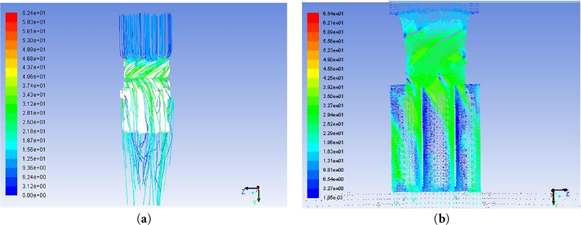
Figure 3: Air blower. (a) Velocity streamline diagram; (b) Velocity vector contour
As can be seen in Fig. 3a, the gas flows backwards along the guide impeller under the influence of inertia after passing through the fan, enters the rear flow channel, and finally flows into the air. However, there is a certain blank area at the outlet, which leads to the generation of eddy currents.
Fig. 3b clearly shows that the size of the vector arrow represents the magnitude of the velocity, and the direction of the arrow represents the direction of the velocity. This indicates that the wind velocity, after being exported through the fan, acts directly on the guide impeller and enters the rear flow channel through the guide impeller. The rear flow channel is mainly composed of straight plates, which has a certain obstruction effect on the flow direction, so that a large vortex is formed in the flow channel. These eddy currents not only have an impact on the formation of noise, but also cause energy losses and affect the outlet flow velocity.
Hair dryer noise can be divided into rotational noise and eddy current noise. Rotating noise, also known as discrete noise, is a discrete peak on a spectrogram. Eddy current noise is known as broadband noise, which is a relatively flat and broad part of the spectrum. The noise spectrum of the hair dryer obtained by numerical simulation in this paper is shown in Fig. 4.
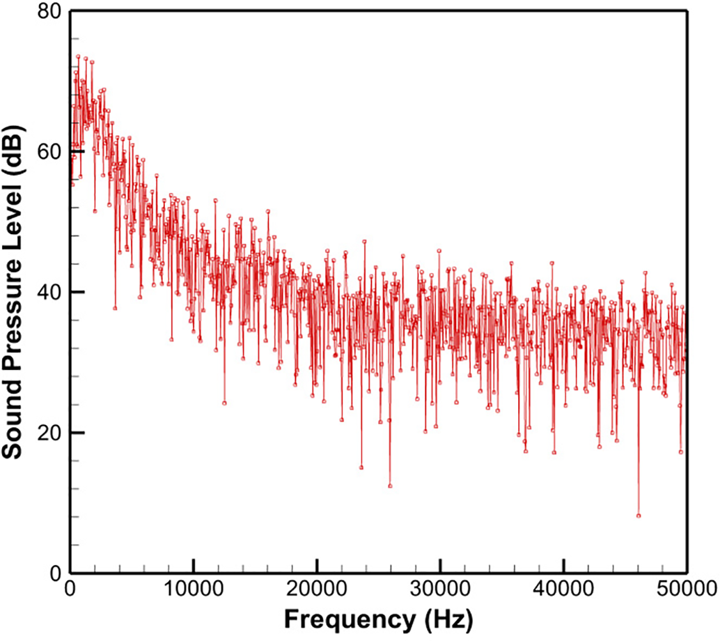
Figure 4: Spectrogram of the sound pressure level of the original impeller
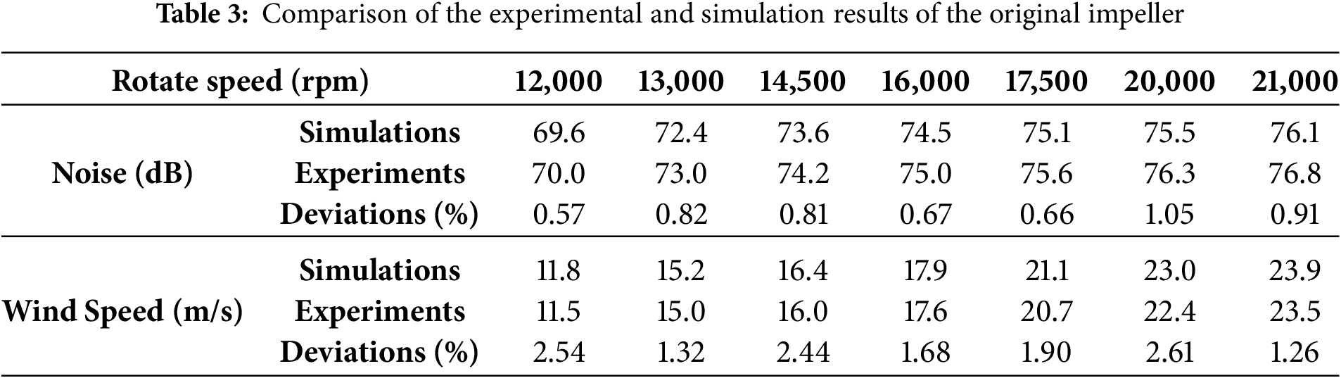
From the spectrum above, it can be seen that the maximum noise values are all located at the fundamental frequency of the rotational noise at the corresponding speed. And as the rotational speed increases, the proportion of rotational noise in the overall aerodynamic noise continues to expand. However, overall, aerodynamic noise is still mainly composed of eddy current noise. The turbulent flow and random pulsation of the fluid on the blade surface and in the flow channel are large, which easily leads to boundary layer separation, vortex mixing, and shedding. Therefore, vortex noise contributes the most to the entire aerodynamic noise at this time. When the fan speed increases and the flow rate increases, the load on the fan blades is relatively small, and the eddy current noise will decrease accordingly, while the rotational noise will increase accordingly. According to the flow field simulation data, the wind speed at the outlet of the hair dryer under standard working conditions (28 V, 20,000 rpm) is 23 m/s, the deviation value between the original impeller experimental test result of 22.4 m/s is 2.61%, the simulated noise result is 75.5 dB, and the deviation value between the original impeller experimental test result of 76.3 is 1.05%.
The comparison of noise and wind speed data proves that the simulation model is basically in line with the actual situation, as shown in Table 3. The design of the guide impeller and runner of the hair dryer is flawed, which has a significant impact on the aerodynamic noise, which in turn affects the overall performance of the hair dryer. In order to effectively reduce the aerodynamic noise, the following optimization scheme is proposed in this study, which improves the uniformity of the flow field and reduces the eddy current phenomenon by optimizing the number, shape and angle of the guide impeller and the rear runner baffle, so as to achieve the purpose of reducing noise.
4 Optimization Design and Experimental Results
After multiple design optimizations of the number, shape, and angle of the guide blades and the rear flow passage baffles, we found that the leading edge of the guide blades is the area directly in contact with the fan’s wake, and optimizing its airfoil design can effectively reduce drag. Furthermore, using a straight baffle design for the rear flow passage may lead to poor flow through the air duct, while a spiral flow passage design helps stabilize the flow and reduce aerodynamic noise. Based on these findings, a relatively optimal design model has been evaluated, as shown in Fig. 5. In this model, five rotors are used for the guide vanes, and the airfoil is selected as NACA2412, forming a specific angle of approximately 30° with the vertical direction, which is consistent with the incoming flow angle. The NACA 2412 airfoil performs well under low-speed flight conditions mainly due to its design features, aerodynamic performance, and ease of manufacturing. The lift-to-drag ratio of the NACA 2412 airfoil varies at different angles of attack, typically resulting in relatively high lift-to-drag ratios at smaller angles of attack (0° to 12°). In an ideal scenario, the lift-to-drag ratio of the NACA 2412 airfoil can reach approximately 10 to 15. At the same time, the structure of the rear flow passage is designed as a spiral guide plate, which works in conjunction with the drain plate corresponding to the tail of the guide blades, significantly improving the guiding effect.
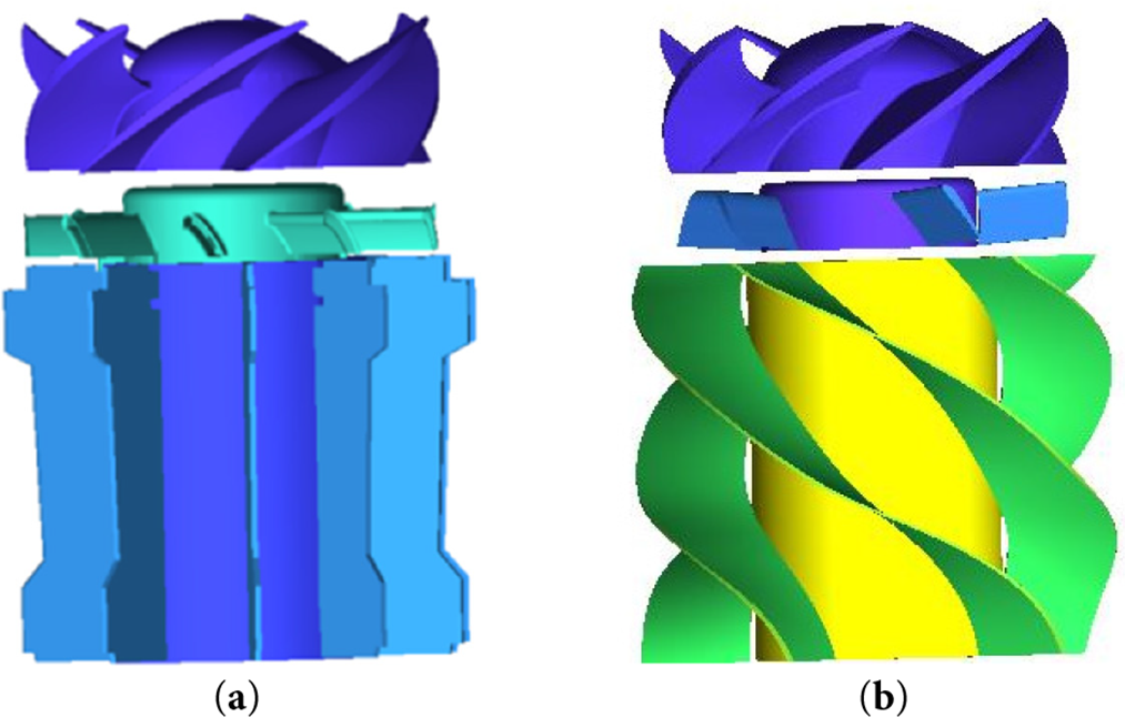
Figure 5: Hair dryer model. (a) Original model; (b) Optimized model
The flow channel of the main body of the hair dryer was simulated in detail, and the velocity field streamline and its vector distribution in the cavity of the runner equipment were successfully reproduced. Through the cross-sectional analysis of the simulation results, a representative plane was selected for detailed observation, as shown in Fig. 6. It is clear from the vector diagram that the fluid flows smoothly in the rear flow channel without any significant eddy currents, and the wind speed under standard operating conditions indicates that the optimized flow channel design has achieved remarkable results in reducing energy loss and aerodynamic noise.
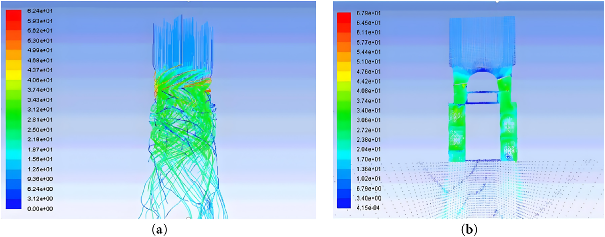
Figure 6: Optimized hair dryer flow channel. (a) Velocity streamline; (b) Velocity vector contour
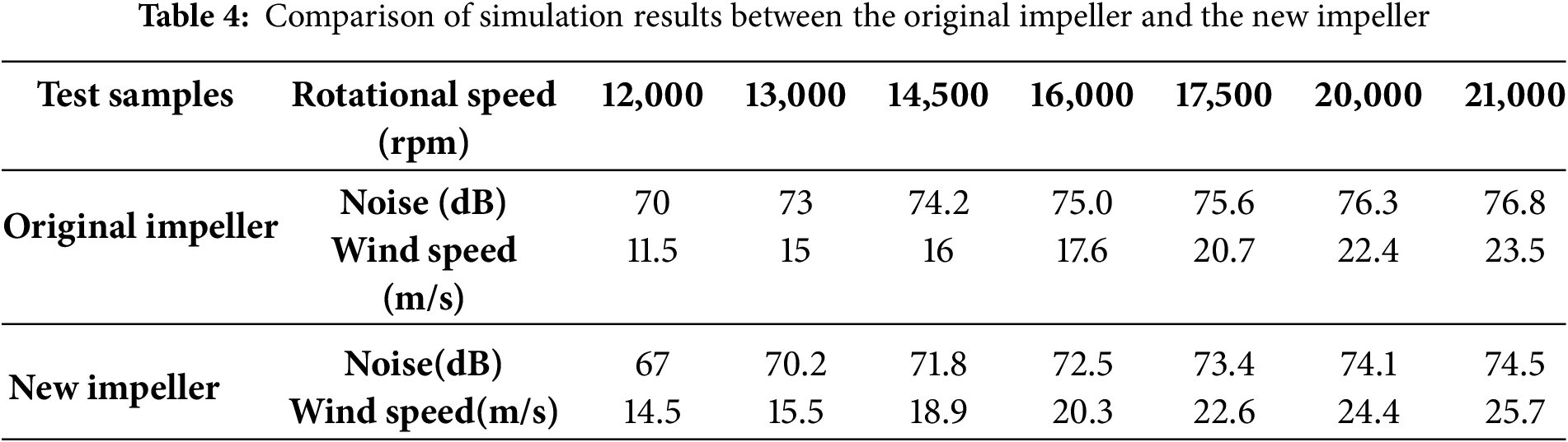
As can be seen from the sound pressure level spectrogram in Fig. 7 and Table 4, the original impeller noise is 76.3 dB and the wind speed is 22.4 m/s at the rated operating condition of 20,000 rpm. The noise of the new impeller is 74.1 dB and the wind speed is 24.4 m/s. At the rated 17,500 rpm, the original impeller noise is 75.6 dB and the wind speed is 20.7 m/s. The noise of the new impeller is 73.4 dB and the wind speed is 22.6 m/s. Under the same speed, the new design impeller is significantly better than the original impeller in terms of noise control and wind speed increase, and the new design impeller has lower noise and higher wind speed than the original impeller.
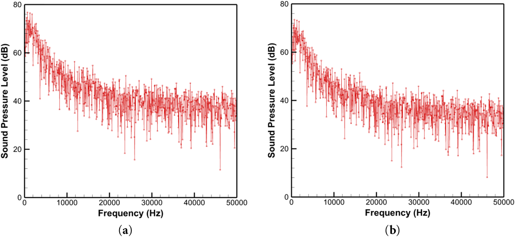
Figure 7: Spectrogram of sound pressure level under rated operating condition (20,000 rpm). (a) Original impeller; (b) New impeller
This study focuses on the aerodynamic noise problem in the flow channel of high-speed hair dryers. By combining CFD simulation with experimental verification, the structure of the guide impeller and rear flow channel was optimized, revealing the key influence of flow channel geometry on the flow field. This provides sufficient theoretical basis for the development of low-noise hair dryer products, and the following results were obtained:
1. The use of a straight baffle in the original channel design resulted in significant eddy currents in the channel area, increasing turbulence noise.
2. By optimizing the spiral guide plate design of the flow channel, the uniformity of the flow field is significantly improved, and the outlet vortex is basically eliminated.
3. Underrated conditions, the optimized impeller reduces noise from 76.3 to 74.1 dB and increases wind speed from 22.4 to 24.4 m/s, achieving a dual effect of noise reduction and performance improvement.
Acknowledgement: Not applicable.
Funding Statement: This research was supported by Research Project of Zhuhai City Polytechnic (Grant No. 2024KYBS06) and Education Research Project of Zhuhai City Polytechnic (Grant No. JY20250404).
Author Contributions: The authors confirm contribution to the paper as follows: study conception and design: Ya Li; data collection: Yu Lu, Yucong Lin; analysis and interpretation of results: Min Deng; draft manuscript preparation: Shanyi Hao. All authors reviewed the results and approved the final version of the manuscript.
Availability of Data and Materials: The data that support the findings of this study are available on request from the corresponding author.
Ethics Approval: Not applicable.
Conflicts of Interest: The authors declare no conflicts of interest to report regarding the present study.
References
1. Akhmetov B, Gupta S, Ahuja KK. Noise source ranking of a hairdryer. In: Proceedings of the 20th AIAA/CEAS Aeroacoustics Conference; 2014 Jun 16–20; Atlanta, GA, USA. doi:10.2514/6.2014-3184. [Google Scholar] [CrossRef]
2. Dolder CN, Fletcher MD, Jones SL, Lineton B, Dennison SR, Symmonds M, et al. Measurements of ultrasonic deterrents and an acoustically branded hairdryer: ambiguities in guideline compliance. Acoust Soc Am. 2018;144(4):2565–74. doi:10.1121/1.5064279. [Google Scholar] [PubMed] [CrossRef]
3. Deshmukh SH, Gogte CL. Effect of bionic blade surface on performance improvement of paddy field impeller. J Braz Soc Mech Sci. 2025;47(1):673. doi:10.1007/s40430-024-05320-z. [Google Scholar] [CrossRef]
4. Zhang AT, Zhou BS, Mao CZ, He DJ, Fang EX. A design method of volute profile of multi-blade centrifugal fan based on DRBF model. Phys Fluids. 2023;35(12):17. doi:10.1063/5.0180530. [Google Scholar] [CrossRef]
5. Paramasivam K, Rajoo S, Romagnoli A, Yahya WJ. Tonal noise prediction in a small high speed centrifugal fan and experimental validation. Appl Acoust. 2017;125:59–70. doi:10.1016/j.apacoust.2017.04.009. [Google Scholar] [CrossRef]
6. Hasan MZ, Ahammed R. Noise reduction of ceiling fans in mass production applying DMAIC-six sigma approach. J Nondestruct Eval Diagn Progn Eng Syst. 2021;4(3):1–13. doi:10.1115/1.4050264. [Google Scholar] [CrossRef]
7. Costa FP, Andersson N, Takachi JT, Bringhenti C. Coupled unsteady RANS and FW-H methodology for aeroacoustics prediction of high-speed propellers. In: Proceedings of the 28th AIAA/CEAS Aeroacoustics 2022 Conference; 2022 Jun 14–17; Southampton, UK. doi:10.2514/6.2022-3089. [Google Scholar] [CrossRef]
8. Marcondes Orselli R, Souza Carmo B, Lauterjung Queiroz R. Noise predictions of the advanced noise control fan model using lattice Boltzmann method and Ffowcs Williams-Hawkings analogy. J Braz Soc Mech Sci. 2018;40(1):1–23. doi:10.1007/s40430-018-0982-2. [Google Scholar] [CrossRef]
9. Sadeghimalekabadi M, Davari A, Fadaei M. Noise reduction in small wind turbines with optimized serrated blades. Phys Fluids. 2024;36(5):057135. doi:10.1063/5.0202934. [Google Scholar] [CrossRef]
10. Hashim HM, Dogruoz MB, Arik M. Acoustic analysis of an Axial fan. In: 2017 16th IEEE Intersociety Conference on Thermal and Thermomechanical Phenomena in Electronic Systems (ITherm); 2017 May 30–Jun 2; Orlando, FL, USA. p. 645–51. doi:10.1109/ITHERM.2017.7992548. [Google Scholar] [CrossRef]
11. Chernenko VV, Chernenko DV. Flow model in the impeller of a centrifugal pump. IOP Conf Ser Mater Sci Eng. 2021;1155(1):012065. doi:10.1088/1757-899X/1155/1/012065. [Google Scholar] [CrossRef]
12. Nasyrova N, Glovatsky O, Ergashev R, Rashidov J, Kholbutaev B. Design aspects of operation of water supply facilities of pumping stations. E3S Web Conf. 2021;274(1):3008. doi:10.1051/E3SCONF/202127403008. [Google Scholar] [CrossRef]
13. Frese F, Einzinger J, Will J. Design optimisation of an impeller with CFD and Meta-Model of optimal Prognosis (MoP). In: Proceedings of the 10th International Conference on Turbochargers and Turbocharging; 2012 May 16–17; London, UK. p. 121–34. doi:10.1533/9780857096135.3a.121. [Google Scholar] [CrossRef]
14. Chandrasekaran M, Santhanam V, Venkateshwaran N. Impeller design and CFD analysis of fluid flow in rotodynamic pumps. Mater Today Proc. 2021;37:2153–7. doi:10.1016/j.matpr.2020.07.637. [Google Scholar] [CrossRef]
15. Bandarkar AW, Sozer Y, Abreu-Garcia JAD. CFD based design of an impeller for a novel integrated motor-compressor system. In: Proceedings of the 2019 IEEE Energy Conversion Congress and Exposition (ECCE); 2019 Sep 29–Oct 3; Baltimore, MD, USA. p. 3820–4. doi:10.1109/ecce.2019.8912680. [Google Scholar] [CrossRef]
16. Menter F. Two-equation eddy-viscosity turbulence models for engineering applications. AIAA J. 1994;32(8):1598–605. doi:10.2514/3.12149. [Google Scholar] [CrossRef]
17. Spalart P, Allmaras S. A one-equation turbulence model for aerodynamic flows. In: 30th Aerospace Sciences Meeting and Exhibit; 1992 Jan 6–9; Reno, NV, USA. doi:10.2514/6.1992-439. [Google Scholar] [CrossRef]
18. ISO 3744. Acoustics—determination of sound power levels and sound energy levels of noise sources using sound pressure. Geneva, Switzerland: International Organization for Standardization; 2010. [Google Scholar]
19. Sugimoto R, James A, Mcalpine A, Astley RJ. CFD/CAA coupling for the prediction of fan tone noise propagation and radiation through a drooped intake. In: Proceedings of the 28th AIAA/CEAS Aeroacoustics 2022 Conference; 2022 Jun 14–17; Southampton, UK. doi:10.2514/6.2022-3100. [Google Scholar] [CrossRef]
20. Jeong BK, Lee H, Won C. Study on the improvement of flow velocity by modifying the shape of the hair dryer impeller based on computational analysis. J Korean Soc Manuf Technol Eng. 2022;31(3):191–6. doi:10.7735/ksmte.2022.31.3.191. [Google Scholar] [CrossRef]
21. Zhang J, Guo Z, Han S, Krajnovi’C S, Sheridan J, Gao G. An IDDES study of the near-wake flow topology of a simplified heavy vehicle. Transp Safety Environ. 2022;4(2):18. doi:10.1093/tse/tdac015. [Google Scholar] [CrossRef]
22. Zhu WJ, Shen WZ, Barlas E, Bertagnolio F, Srensen JN. Wind turbine noise generation and propagation modeling at DTU Wind Energy: a review. Renew Sust Energ Rev. 2018;88(10):133–50. doi:10.1016/j.rser.2018.02.029. [Google Scholar] [CrossRef]
23. Thé J, Yu H. A critical review on the simulations of wind turbine aerodynamics focusing on hybrid RANS-LES methods. Energy. 2017;138(Part 1):257–89. doi:10.1016/j.energy.2017.07.028. [Google Scholar] [CrossRef]
24. Li J, Liu R, Yuan P, Pei Y, Cao R, Wang G. Numerical simulation and application of noise for high-power wind turbines with double blades based on large eddy simulation model. Renew Energ. 2020;146(1):1682–90. doi:10.1016/j.renene.2019.07.164. [Google Scholar] [CrossRef]
Cite This Article
 Copyright © 2025 The Author(s). Published by Tech Science Press.
This work is licensed under a Creative Commons Attribution 4.0 International License , which permits unrestricted use, distribution, and reproduction in any medium, provided the original work is properly cited.
 Downloads
 Citation Tools