
 Submit a Paper
 Propose a Special lssue
 Open Access
ARTICLE

Experimental Investigation of Fracture Propagation Induced by Supercritical CO2 in Deep Shale Reservoirs
1 Wuqi Oil Production Plant, Shaanxi Yanchang Petroleum, Xi’an, 716000, China
2 State Key Laboratory of Oil and Gas Reservoir Geology and Exploitation, Southwest Petroleum University, Chengdu, 610500, China
* Corresponding Author: Dan Zhang. Email:
Fluid Dynamics & Materials Processing 2025, 21(8), 1917-1934. https://doi.org/10.32604/fdmp.2025.067114
Received 25 April 2025; Accepted 17 July 2025; Issue published 12 September 2025
 View Full Text
 Download PDF
Abstract
Deep shale reservoirs are often associated with extreme geological conditions, including high temperatures, substantial horizontal stress differences, elevated closure stresses, and high breakdown pressures. These factors pose significant challenges to conventional hydraulic fracturing with water-based fluids, which may induce formation damage and fail to generate complex fracture networks. Supercritical carbon dioxide (SC-CO2), with its low viscosity, high diffusivity, low surface tension, and minimal water sensitivity, has attracted growing attention as an alternative fracturing fluid for deep shale stimulation. This study presents a series of true triaxial large-scale physical experiments using shale samples from the Longmaxi Formation in the southern Sichuan Basin to investigate fracture initiation and propagation behavior under different fracturing fluids. The results show that, under identical experimental conditions, SC-CO2 fracturing results in a significantly lower breakdown pressure compared to slick water and promotes the formation of more complex fracture geometries. These advantages are attributed to both the favorable flow characteristics of SC-CO2 and its potential chemical interactions with shale minerals. The findings not only confirm the effectiveness of SC-CO2 as a fracturing fluid in deep shale environments but also provide new insights into its fracture propagation mechanisms.Keywords
With the continuous and rapid advancement of shale gas exploration and development, an annual production capacity of 20 billion cubic meters has been established in marine shale formations at burial depths shallower than 3500 m. Shale gas is gradually becoming the main driver of domestic natural gas production growth. Deep shale formations with burial depths exceeding 3500 m are expected to be the primary contributors to future production increases [1,2]. In particular, in certain deep shale regions, deep shale resources buried between 3500–4000 m account for approximately 80% of the total shale gas resources at depths shallower than 4500 m. However, these deep shale formations pose significantly greater challenges and require higher development costs due to their greater depths, more complex geological conditions, and well-developed fault systems [3,4].
Traditional water-based fracturing fluids have played a critical role in unconventional reservoir stimulation. Large-scale hydraulic fracturing is commonly employed in shale gas extraction, which typically consumes massive amounts of water and proppant, described as “thousands of cubic meters of proppant and tens of thousands of cubic meters of water”. This practice leads to concerns such as reservoir damage, groundwater contamination, and substantial water consumption [5]. Moreover, shale reservoirs often contain high clay mineral content, and water-based fracturing fluids can cause clay swelling upon hydration, resulting in formation damage and reduced stimulation effectiveness [6,7]. SC-CO2 fracturing has emerged as a promising technology for unconventional oil and gas reservoirs, offering minimal water usage and enhanced fracture generation capacity. Replacing conventional water-based fluids with SC-CO2 is currently a focus of intense research for efficient shale gas development [8–11]. Moreover, recent field pilot studies and numerical simulations have provided further evidence of SC-CO2 effectiveness in deep shale reservoirs, underscoring the importance of this work. Supercritical CO2 (SC-CO2) fracturing has attracted increasing interest in recent years due to its unique physical and chemical properties, such as low viscosity, high diffusivity, and the ability to reduce reservoir damage and enhance gas desorption. These characteristics make SC-CO2 fracturing particularly promising for unconventional reservoirs like deep shale formations. However, field-scale application of SC-CO2 fracturing still faces several limitations: (1) Transporting and storing large volumes of liquid or supercritical CO2 in remote field locations requires specialized high-pressure equipment and infrastructure, which can significantly complicate operations and increase logistical burdens. (2) Safety Concerns: CO2 is a colorless, odorless, and asphyxiating gas at high concentrations. Any leakage during compression, transportation, or fracturing operations may pose serious safety hazards to personnel and equipment, necessitating stringent monitoring and control measures. (3) Economic Cost: The cost of producing, compressing, transporting, and maintaining supercritical CO2 conditions in the field is considerably higher than that of traditional water-based fracturing fluids. Without economies of scale or integration with carbon capture, utilization, and storage (CCUS) strategies, its widespread adoption remains economically challenging. (4) Operational Limitations: SC-CO2’s low viscosity limits its sand-carrying capacity, which may affect proppant transport and placement, especially in long horizontal wells. Additional techniques or additives may be required to enhance its effectiveness in practical operations. Despite these limitations, the environmental benefits and enhanced recovery potential of SC-CO2 fracturing justify further research and pilot-scale field trials. Integrating SC-CO2 fracturing with CO2 sequestration strategies may provide dual benefits of energy production and carbon management in the future [12–14].
Since the development of CO2 fracturing technology, scholars have continuously improved true triaxial laboratory testing devices and methods to investigate the fracture initiation mechanisms and propagation patterns of SC-CO2 fracturing. Comparative studies involving water-based, oil-based, and other fracturing fluids have revealed that SC-CO2 generally exhibits lower breakdown pressures and promotes the formation of more complex and branched fracture networks [15,16]. Verdon et al. [17] conducted simultaneous fracturing experiments using CO2 and water-based fluids, demonstrating that CO2 can achieve comparable fracturing performance. Ishida et al. [18] performed true triaxial fracturing experiments on granite and observed that the low viscosity of SC-CO2 facilitates the development of complex fractures at lower breakdown pressures. Li et al. [19] explored the effects of different fracturing fluids on fracture morphology in shale and found that, under the same conditions, the breakdown pressures followed the order CO2 > N2 > water, and that fracture roughness and local damage were greatest with CO2. However, CO2 was not in a supercritical state in that study, and thus its unique fracturing characteristics were not fully represented. Zhang et al. [20] compared SC-CO2 and water-based fracturing in shale and found that SC-CO2 reduced breakdown pressure by more than 50%. It also more effectively induced secondary fractures and connected natural fractures and bedding planes to form complex fracture networks. Wang et al. [21] observed in Niobrara shale that SC-CO2 injection caused instantaneous fracturing accompanied by a notable temperature drop, although the presence of pre-existing fractures may have influenced the results. Hu et al. [22] conducted SC-CO2 and water-based fracturing experiments on shale and synthetic sandstone, revealing that SC-CO2 required lower breakdown pressures and generated acoustic emission energy one to two orders of magnitude higher than hydraulic fracturing. Avanthi Isaka et al. [23] performed a series of SC-CO2 fracturing experiments on Harcourt granite under varying confining pressures and temperatures, confirming that SC-CO2 exhibits lower breakdown pressures than water-based fluids and more easily produces narrow, branched fractures under high temperatures. He et al. [24] conducted uniaxial fracturing tests and SEM analyses, showing that bedding planes influence fracture morphology and initiation pressure, and that SC-CO2 promotes micro-shear slip, leading to complex fracture networks. Al Shafloot et al. [25] reported higher breakdown pressure for SC-CO2 than for water in Green River shale, attributing the difference to fluid-rock interactions, a finding inconsistent with most other studies. Hu et al. [26] compared fracturing effects of water, liquid CO2, and SC-CO2 on tight sandstone, and found that SC-CO2 significantly increased post-fracturing porosity and permeability. While water-based fracturing produced smooth, planar fractures, liquid CO2 created short main fractures with some microcracks, and SC-CO2 generated localized fracture networks with the lowest breakdown pressure. Li et al. [27] further investigated the dominant factors controlling SC-CO2 fracture propagation via physical experiments. Although most experimental studies have shown that SC-CO2 fracturing results in a lower breakdown pressure compared to water fracturing [12,22], some studies have reported that SC-CO2 may exhibit a higher breakdown pressure [25], leading to key controversies regarding its fracture initiation mechanism. Researchers suggest that such discrepancies may be closely related to factors such as injection rate, experimental temperature and pressure conditions, rock type, and structural characteristics. In particular, chemical interactions between SC-CO2 and rock-such as carbonate dissolution or the weakening of clay mineral structures-may play an important role in reducing rock strength and promoting fracture propagation [16,28]. Therefore, a deeper understanding of fluid–rock coupling effects during SC-CO2 fracturing and their influence on breakdown behavior remains a crucial direction for future research.
Currently, laboratory SC-CO2 fracturing experiments have reached maximum test temperatures of 300°C [23], confining pressures of up to 52.5 MPa [29], and horizontal stress differences of up to 10 MPa [30]. However, these conditions still fall short of replicating the true in-situ environment of deep marine shale formations, which typically exhibit temperatures of 110°C–145°C, closure stresses of 80–95 MPa, horizontal stress differences of 15–25 MPa, and pore pressures of 60–80 MPa. As a result, the fracture propagation behavior of SC-CO2 under actual deep shale conditions remains unclear. Furthermore, most existing physical experiments have focused on describing experimental phenomena, with limited analysis of the underlying mechanisms. Based on a review of prior experimental conditions and findings, a series of laboratory experiments is designed and conducted using different fracturing fluids on deep shale samples from the Luzhou block in southern Sichuan, with the aim of investigating the fracture propagation mechanisms of SC-CO2 fracturing under deep shale reservoir conditions.
2.1 Shale Specimen Preparation and Fracturing Test Apparatus
The shale specimens used in this study were obtained from a representative deep shale formation characterized by well-developed bedding planes and complex structural features. The in-situ three-dimensional stress state of the deep shale in the selected region was previously determined based on wellbore data. The results indicate that the maximum horizontal principal stress exceeds the vertical stress, which in turn is greater than the minimum horizontal stress. Specifically, the maximum horizontal stress ranges from 98.15 to 116.93 MPa, with an average of 105.24 MPa; the minimum horizontal stress ranges from 84.28 to 104.28 MPa, with an average of 92.06 MPa; and the vertical stress varies from 89.75 to 112.08 MPa, averaging 99.11 MPa. The horizontal stress difference ranges between 11.49 and 18.61 MPa, with a mean value of 13.81 MPa.
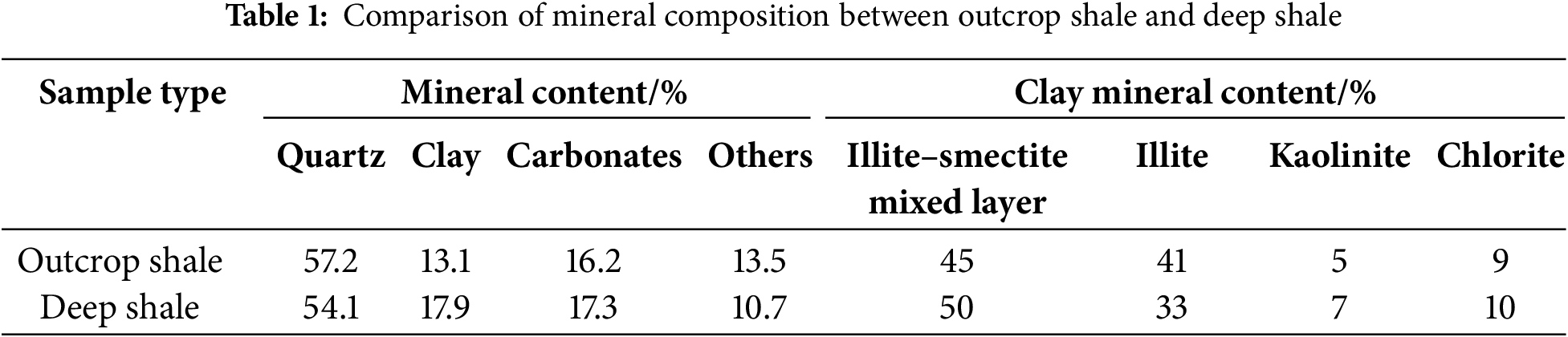
For the rock mechanics testing, core samples were obtained from typical deep burial depths ranging from approximately 3800 to 4200 m. Uniaxial compression tests were conducted to determine mechanical properties. The Young’s modulus of the shale ranged from 21.31 to 69,060 MPa, with an average of 38,700 MPa. The Poisson’s ratio ranged from 0.188 to 0.393, with an average of 0.259. The tensile strength of shale samples from the Luzhou block was found to be in the ranged of 4.61–21.06 MPa, with an average of 11.40 MPa. Outcrop samples of the Longmaxi Formation shale from the Luzhou block were selected and precision-cut into four cubic specimens measuring 300 mm × 300 mm × 300 mm using a wire-cutting machine. The porosity and pore size distribution of the standard cores were measured using Nuclear Magnetic Resonance (NMR) analysis. the measured porosity is 6.79%, indicating a medium porosity level. The pore structure is dominated by mesopores and micropores. The presence of microfractures and bedding planes may contribute to the relatively high porosity. The gas permeability was measured at 0.095 mD, classifying the shale as a low-permeability rock with poor fluid mobility. The outcrop samples exhibited a Young’s modulus of 30,330 MPa, a Poisson’s ratio of 0.27, and a tensile strength of 8.59 MPa. By comparing the mineral compositions of outcrop shale and deep shale, it is found that there is no significant difference between the two, and both exhibit a high content of brittle minerals (Table 1).
The experimental apparatus used in this study is a self-developed physical simulation system for hydraulic fracturing of shale outcrops. The system mainly consists of a true triaxial fracturing chamber, safety valves, check valves, tubing and valve assemblies, lifting equipment, a triaxial hydraulic loading system, borehole drilling equipment, sealing sleeves, acoustic monitoring system, pressure transducers, digital control panels, a constant-rate and constant-pressure fracturing pump, curing agent containers, piston vessels, rubber sleeves, an electrical control cabinet, and a data acquisition and processing system. A photograph of the experimental setup is shown in Fig. 1, and the layout of the acoustic emission sensors is illustrated in Fig. 2. The schematic diagrams of the experimental system are shown in Fig. 3. The stress loading unit consists of a high-pressure gas cylinder connected to a gas-liquid transition cylinder, which is further connected to a triaxial hydraulic system. A pressure transmitter is installed on the triaxial hydraulic system to control the intake and release of hydraulic fluid. In addition, three pressure sensors are mounted on the triaxial hydraulic system to monitor stress loading in the X, Y, and Z directions. Each sensor has a measurement range of 0–70 MPa with an accuracy of 0.1% full scale (FS). Before using the stress loading apparatus, the rock core should be securely clamped. Then, the vent valve on the gas-liquid transition cylinder is closed, and the pressure transmitter is switched on. The nitrogen cylinder is slightly opened to allow gas flow. A pressure gauge installed on the gas-liquid transition cylinder (range: 0–10 MPa) is used for monitoring. Once the pressure reaches 4–6 MPa, the rear valve of the pressure transmitter is closed. The triaxial servo-hydraulic system is then activated to pump high-pressure fluid into the X, Y, and Z direction bearing plates, thereby applying the required confining pressure.
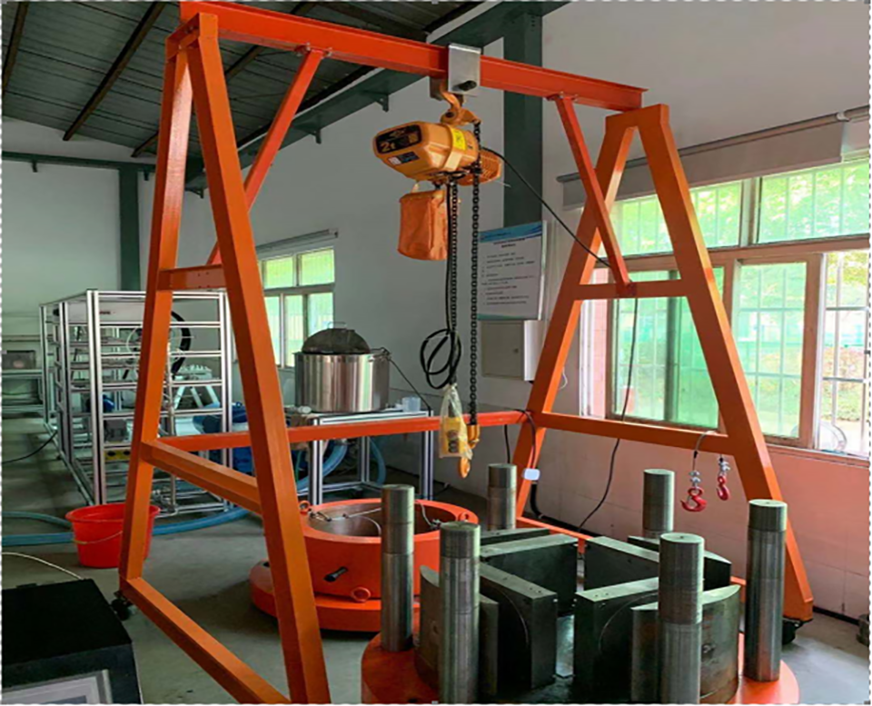
Figure 1: Photograph of the experimental setup
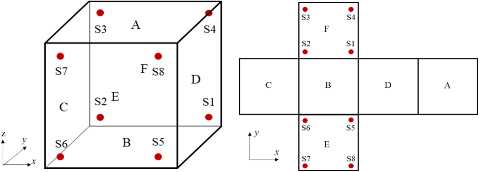
Figure 2: Schematic diagram of the acoustic emission sensor layout and orientation
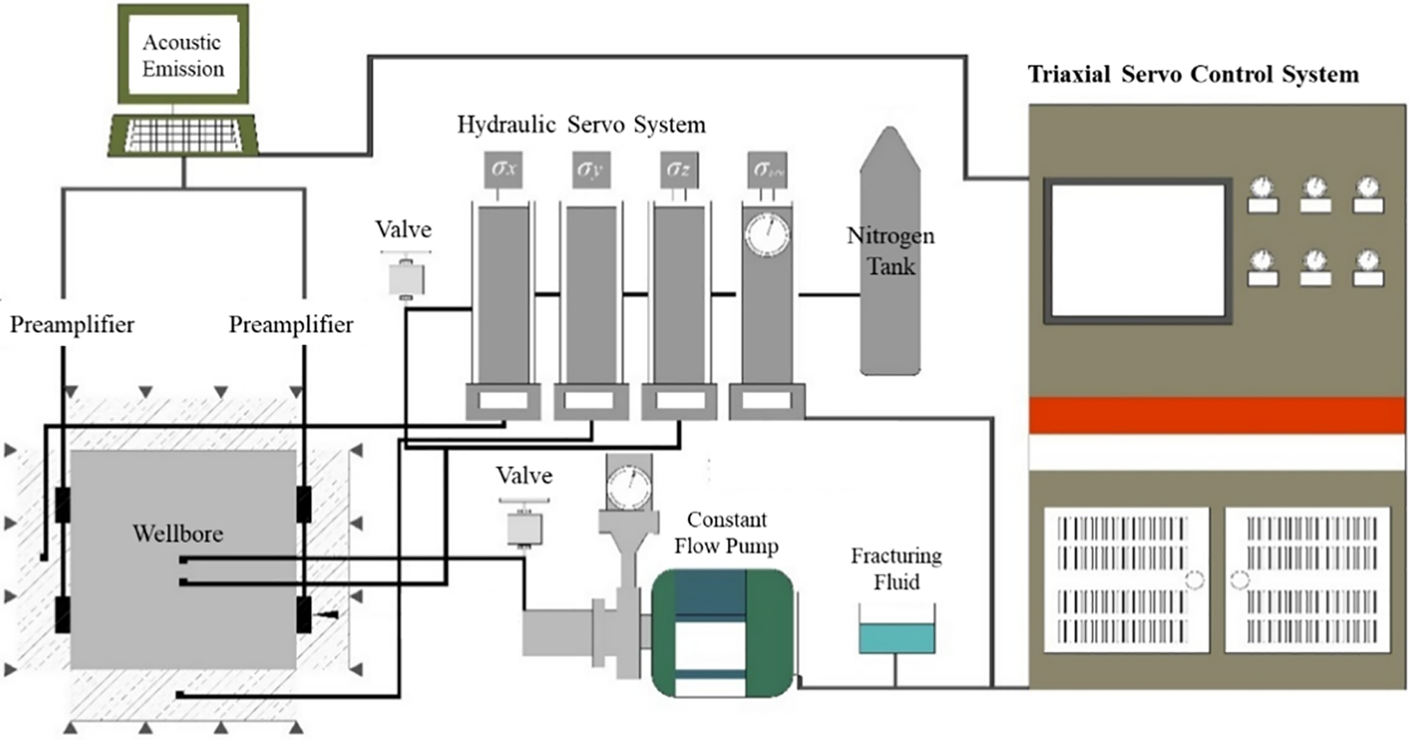
Figure 3: Schematic diagram of the experimental system
In hydraulic fracturing physical experiments, similarity theory is commonly employed to establish similarity criteria, ensuring that the physical and mechanical behavior of the laboratory model accurately represents field-scale conditions. This approach enhances the applicability and generalization of experimental results. A set of similarity criteria for true triaxial hydraulic fracturing physical simulation was first proposed based on the dimensionless form of the three-dimensional fracture propagation control equation. These criteria include similarity indices for injection volume, injection rate, and bottomhole pressure [31].
Building upon this foundation, Hou et al. [32,33] further calculated the correspondence between laboratory injection parameters and field-scale construction parameters under specific burial depths and triaxial in-situ stress conditions in shale formations. Guo et al. [34], based on the second similarity theorem, derived similarity criteria for perforated well hydraulic fracturing experiments by non-dimensionalizing both the fracture initiation and propagation equations. They also established the scaling ratios for relevant physical quantities. The similarity method is a scientific approach for generalizing the results obtained from a specific model (the laboratory scale) to its corresponding prototype (the field scale). When the single-valued boundary conditions of similar physical phenomena are alike, and the corresponding similarity criteria (composed of relevant physical quantities) are equal, the two phenomena can be considered physically similar.
According to the second similarity theorem, if a physical problem involves n independent variables that can be expressed in terms of k fundamental dimensions (e.g., length, mass, time), then the problem can be fully described by n − k dimensionless groups, known as π-numbers, which characterize the essential physics of the system. The general form of any physical equation can be written as:
According to the Buckingham π theorem in dimensional analysis, the following relationship can be established:
If the model and the prototype are similar, then at corresponding points and corresponding times, the similarity criteria must take the same values and follow the same functional relationships. That is, for the prototype:
Based on the similarity theory described above, the physical simulation of fracture propagation in true triaxial hydraulic fracturing experiments and the actual field-scale prototype share the same governing equations. The governing model adopted in this study is based on the relationship between fracture width and internal fracture pressure, derived under the assumptions of linear elasticity, isotropic rock behavior, and dislocation theory.
(1) Stress Equilibrium Equation
where
The effective elastic modulus can be expressed as:
where G is the shear modulus, and ν is the Poisson’s ratio.
(2) Continuity Equation for Fluid Flow
where
The directional fluid mobility can be expressed as follows:
where ki is the permeability in the x, y, or z direction, and μl is the fluid viscosity.
Based on the work of Williams et al. [35], the initial instantaneous leak-off velocity can be expressed as:
where cK is the fluid leak-off volume per unit area, and τi is the time when the fracture surface first comes into contact with the fracturing fluid.
The fracture initiation pressure for a perforated well can be calculated using the following equation:
where σH is the maximum horizontal in-situ stress, σh is the minimum horizontal in-situ stress, σv is the vertical in-situ stress, and σt is the tensile strength of the rock.
Based on the governing equations and single-valued boundary conditions described above, the required experimental parameters for constructing the physical model can be derived using similarity theory. By denoting prototype quantities with an asterisk “*” and model quantities without a symbol, the physical quantities involved in the similarity relationships in the above equation have the following units:
By substituting the prototype physical quantities with the product of the corresponding model quantities and their similarity constants, and then comparing with Eqs. (4)–(10), the following relationships can be obtained:
By rearranging the expressions, the similarity indices of each parameter form the following dimensionless relationships:
The above equations represent the similarity criteria for perforated well fracturing simulation experiments, derived based on the second similarity theorem. The experimental parameters were determined by converting field-scale values according to these criteria.
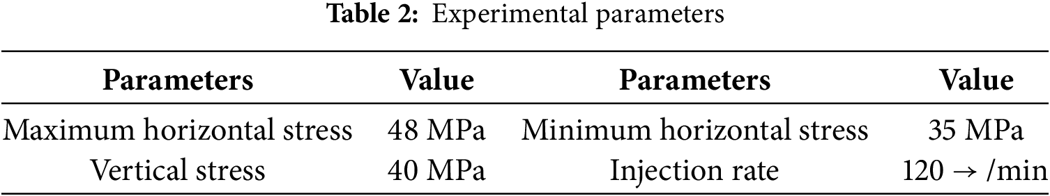
The maximum horizontal stress is set to 105 MPa, the minimum horizontal stress to 92 MPa, and the vertical stress to 100 MPa. The fracturing fluid injection rate is set to 10 m3/min, and the experimental temperature is set at 120°C. According to the established similarity criteria, the corresponding experimental parameters are converted as follows (Table 2):
The detailed experimental steps are as follows:
(1) Pre-experiment sonic velocity calibration was conducted using probe self-check and lead-break tests.
(2) Sensor positioning and assembly: Grooves were machined at the designated sensor locations to fit the acoustic emission (AE) sensors. The AE system was installed, and the true triaxial experimental apparatus was assembled. A vertical borehole was drilled into the center of a pre-cut 300 mm × 300 mm × 300 mm shale outcrop cube to place an artificial wellbore, with a 15 mm open-hole section reserved. The wellbore was sealed with adhesive to complete the preparation of the test specimen. Sonic velocity testing was then performed on the sample. The AE acquisition software was launched, and waveform data acquisition parameters were configured. The specimen was lifted and positioned between the X and Y loading plates. Eight AE sensors were installed by first applying coupling gel (to enhance signal transmission) to each probe and mounting them on the Y-direction loading plate. The opposite ends of the sensors were connected to signal receivers. Finally, the Z-direction loading plate was lifted and placed on top of the specimen.
(3) Enclosure and heating setup: The sealing sleeve was lowered over the specimen into the triaxial fracturing chamber. Pumping pipelines and pressure sensors were connected to the artificial wellbore. The sample endcap was installed, and the pre-tightening nuts were fastened. The heating system was activated, and the target temperature was set.
(4) Loading and pressurization: After reaching the target temperature, the vent valve on the gas-liquid transition cylinder was closed to prevent leakage. The pressure transducer was activated, and the nitrogen cylinder was slightly opened. When the gas pressure gauge on the transition cylinder reached 4–6 MPa, the rear valve of the pressure transducer was closed. The triaxial servo-hydraulic system was then started to inject high-pressure fluid into the X, Y, and Z directions loading plates to apply confining pressure in all three directions.
(5) Fracturing fluid injection: The fluid discharge system was closed. The fracturing fluid was prepared, and the desired injection rate was set. The injection system was activated.
(6) Real-time monitoring and fracturing: The AE system continuously monitored the specimen in real time. Under the action of pump pressure, the specimen fractured, and the AE system detected and recorded signals corresponding to fracture initiation. Once confirmed, the fluid injection system was shut down, marking the end of the experiment.
(7) Specimen retrieval: The pre-tightening nuts were removed. The sealing sleeve, Z-direction loading plate, and the specimen were sequentially extracted using the lifting device.
(8) Post-experiment analysis: Photographs of the fractured specimen were taken. AE data and injection pressure curves were processed and exported for analysis.
The experiment is conducted indoors and simulates a vertical wellbore under specific boundary conditions. The geological setting is simplified to represent a localized point within the formation, allowing for in-depth investigation of the fracture initiation time, breakdown pressure, and near-tip fracture propagation characteristics of the rock specimen under controlled conditions. During the experiment, the rock specimen gradually accumulates stress under the action of internal fluid pressure until it reaches a critical rupture point. At this moment, fracture initiation and propagation occur almost simultaneously, revealing the stress–strain behavior and nonlinear mechanical response of deep shale. Specifically, as the external load increases, internal stresses within the rock concentrate in a localized region. Once the local stress exceeds the rock’s strength limit, microcracks rapidly expand and coalesce into macroscopic fractures.
2.3.1 Results of Hydraulic Fracturing Experiment
The outcrop shale samples from the Longmaxi Formation in the Luzhou block, southern Sichuan Basin, exhibit well-developed bedding planes. A vertical borehole is drilled perpendicular to the bedding direction, and an artificial wellbore is sealed in place. In Specimen 1, a single through-going fracture appears on the lower side of the sample, located relatively far from the base of the artificial wellbore. In Specimen 2, two prominent through-going bonded fractures are observed-one is close to the bottom of the artificial wellbore, while the other is farther away, as shown in Fig. 4.
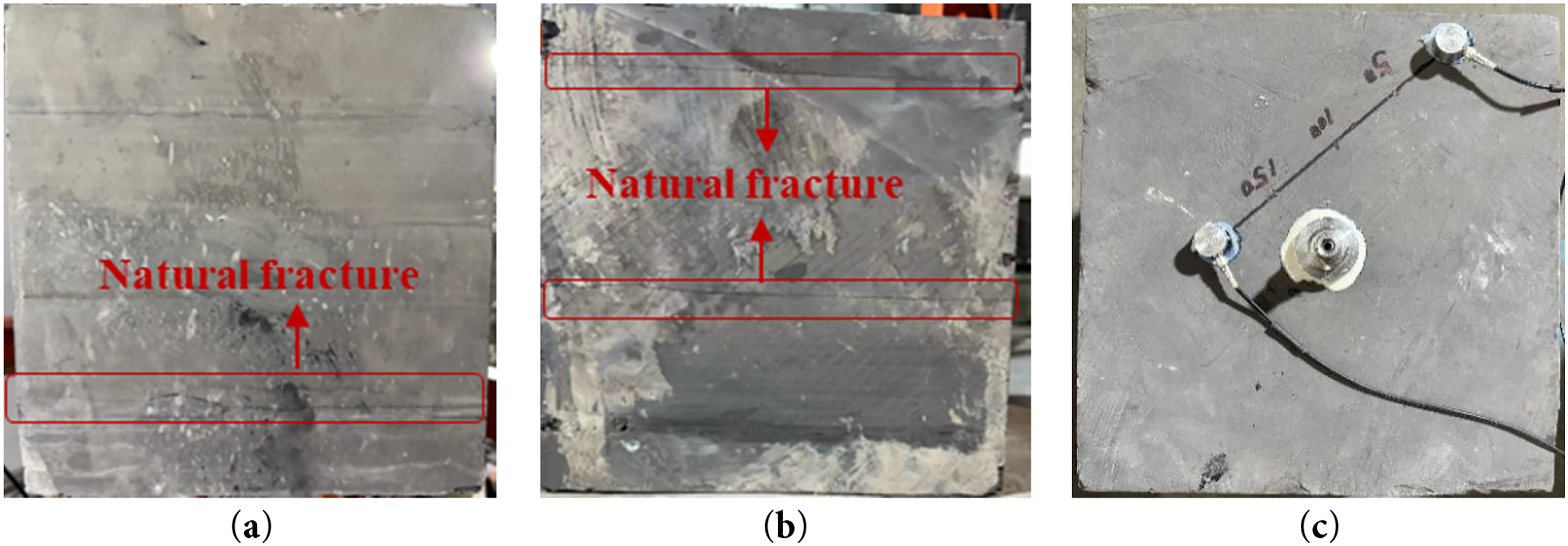
Figure 4: Shale specimen used in the low-viscosity slickwater fracturing experiment. (a) Specimen 1; (b) Specimen 2; (c) Sonic Velocity Test
Two sets of hydraulic fracturing experiments using low-viscosity slickwater are conducted to ensure experimental repeatability.
Following the experimental procedure described earlier, hydraulic fracturing tests are conducted using low-viscosity slickwater with a viscosity of 5 mPa·s. Figs. 5 and 6 show the post-fracturing conditions of Specimen 1 and Specimen 2, respectively. The experimental results indicate that although both tests are conducted under the stress regime where the maximum horizontal principal stress is greater than the vertical stress, which in turn is greater than the minimum horizontal stress, the presence of natural fractures and horizontal bedding planes leads to the formation of horizontal fractures rather than vertical ones. In Specimen 2, in particular, the natural fracture located closer to the bottom of the artificial wellbore is also activated and opened during the fracturing process.
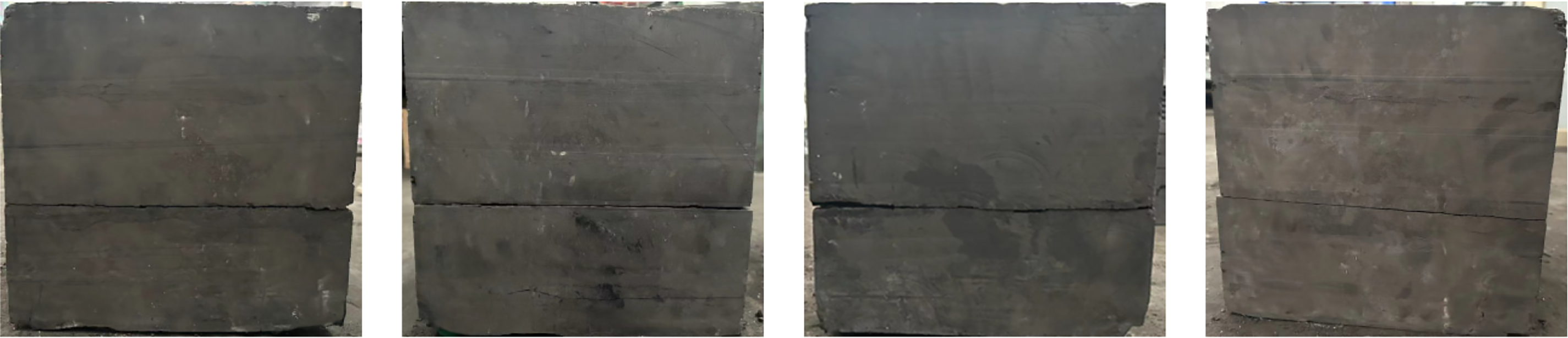
Figure 5: Post-fracturing condition of Specimen 1 after low-viscosity slickwater fracturing
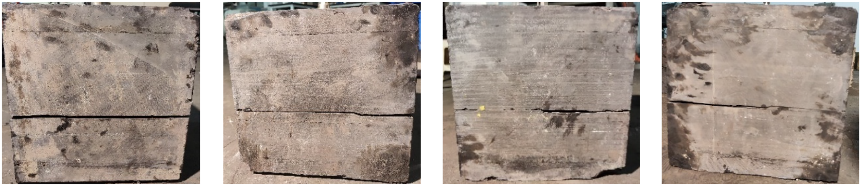
Figure 6: Post-fracturing condition of Specimen 2 after low-viscosity slickwater fracturing
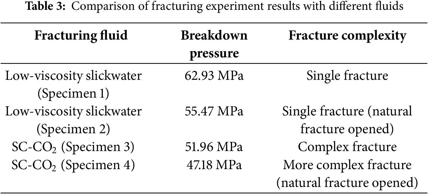
Fig. 7 shows the pump pressure vs. time curves for the two shale specimens under constant injection rate. As slickwater is continuously injected, the pump pressure gradually increases. Specimen 1 reaches its peak strength at 411 s during the fracturing test, with a fracture initiation pressure of 62.93 MPa. Specimen 2 reaches its peak strength at 562 s, with a fracture initiation pressure of 55.47 MPa. Once the fracturing fluid enters the newly formed fractures, the peak pressure drops rapidly as more fluid is injected. The initiation pressure of Specimen 1 is 13.45% higher than that of Specimen 2, indicating that the presence of natural fractures near the open-hole section in Specimen 2 helps reduce the fracture initiation pressure.
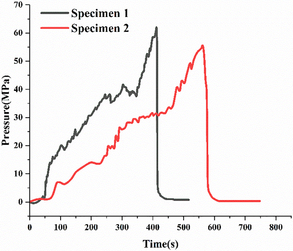
Figure 7: Pump pressure vs. time curves for Specimen 1 and Specimen 2 during low-viscosity slickwater fracturing
Figs. 8 and 9 show the acoustic emission (AE) test results for Specimen 1 and Specimen 2, respectively. The AE event localization accounts for the anisotropy of P-wave velocity [36], with an expected spatial accuracy of a few millimeters. Only AE events that meet the following criteria are considered [37]: (1) the P-wave onset is detected by more than five sensors; (2) both the standard deviation and the maximum difference between observed and calculated arrival times are within 3 microseconds.
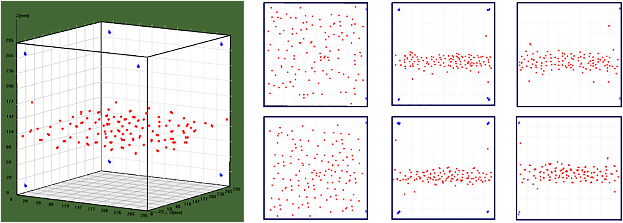
Figure 8: Acoustic emission test results of Specimen 1
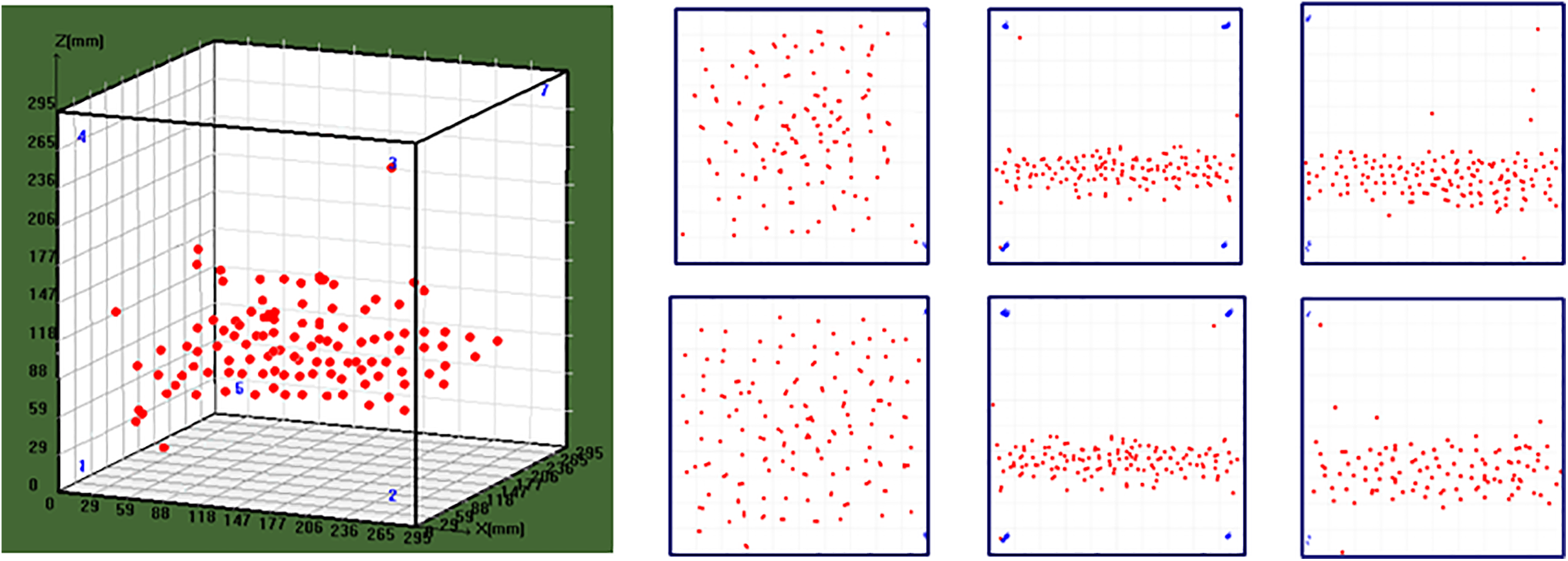
Figure 9: Acoustic emission test results of Specimen 2
In both experiments, the localized AE sources are concentrated on a single plane, indicating that low-viscosity slickwater fracturing generates a single dominant fracture. The AE localization results are consistent with the observed macroscopic fracture patterns in the rock specimens. Signal analysis further reveals that shear failure dominates the fracturing process, primarily due to the presence of natural fractures and weak bedding planes that are prone to shear slip. Tensile failure is also observed but occurs less frequently.
2.3.2 Supercritical CO2 Fracturing Experimental Results
The shale outcrop exhibits well-developed bedding planes. A vertical borehole is drilled perpendicular to the bedding direction, and an artificial wellbore is sealed in place according to the experimental procedure described earlier. Specimen 3 appears relatively intact, with no visible natural fractures. In contrast, Specimen 4 has a prominent through-going bonded fracture located near the bottom of the artificial wellbore on the lower side.
Two sets of hydraulic fracturing experiments are carried out using SC-CO2 on Specimens 3 and 4 (Fig. 10) to ensure the repeatability of the results.
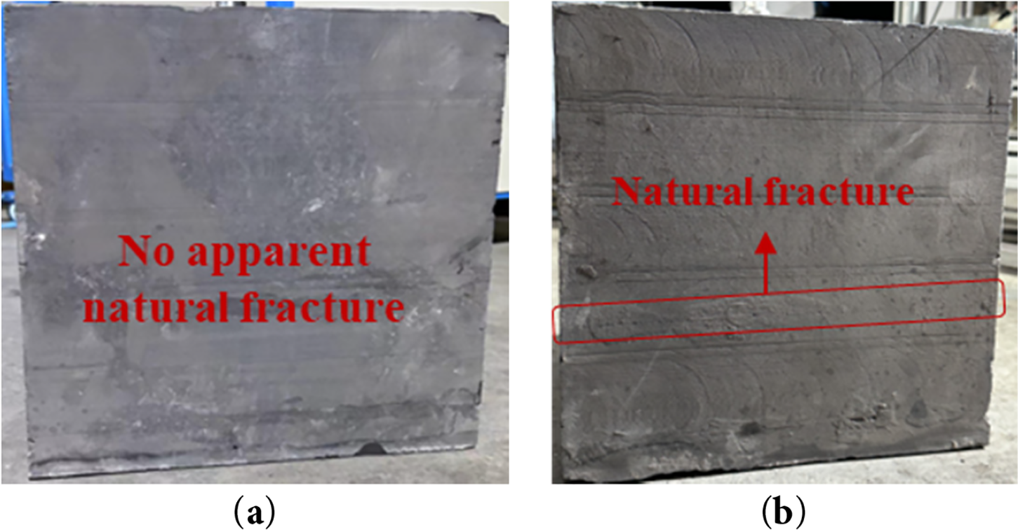
Figure 10: Shale specimens used in the supercritical CO2 fracturing experiments. (a) Specimens 3; (b) Specimens 4
Before the experiment, CO2 is pressurized to 10 MPa using a booster pump. The heating system is set to 50°C, and once both pressure and temperature stabilize, supercritical CO2 injection begins.
Figs. 11 and 12 show the post-fracturing conditions of Specimen 3 and Specimen 4, respectively. The experimental results indicate that under the same confining pressure and injection rate conditions as the low-viscosity slickwater tests, SC-CO2 first opens the bedding planes to form horizontal fractures. It then gradually redirects propagation in the vertical direction and activates additional bedding planes, ultimately forming a complex fracture network within the specimen. Here, complex fracture network’ refers to multiple intersecting fracture branches and non-planar fracture surfaces, rather than a single planar crack.
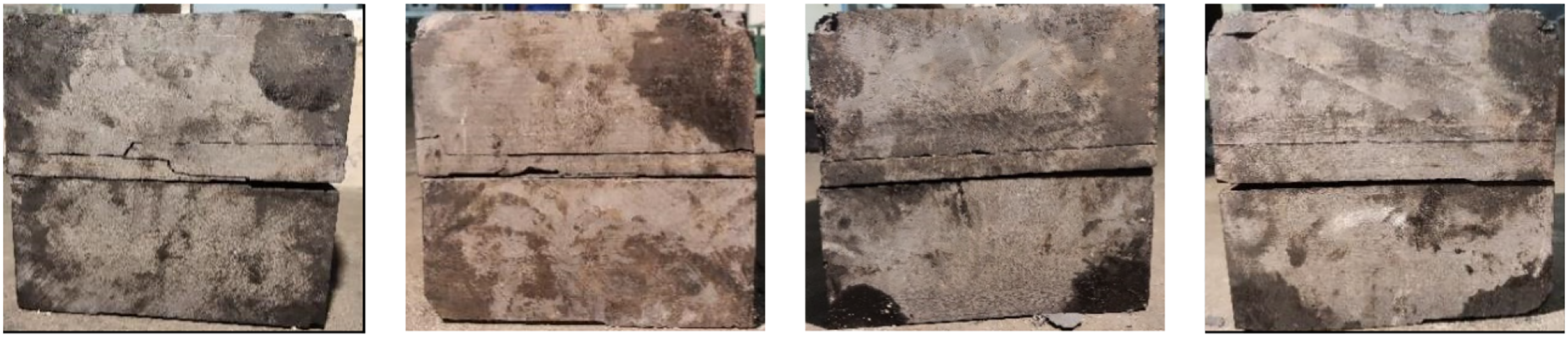
Figure 11: Post-fracturing condition of Specimen 3 after supercritical CO2 fracturing
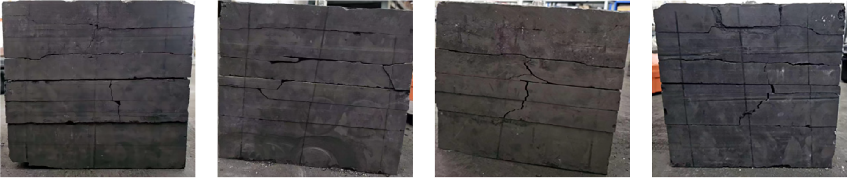
Figure 12: Post-fracturing condition of Specimen 4 after supercritical CO2 fracturing
Fig. 13 presents the pump pressure vs. time curves for Specimens 3 and 4 under a constant injection rate using supercritical CO2. As the injection continues, the pump pressure gradually increases. During the pressurization phase, the rate of pressure increase is relatively low, which is significantly different from that observed in hydraulic fracturing with water. This phenomenon is primarily attributed to the much higher compressibility of supercritical CO2 compared to water, resulting in a lower pressure build-up rate. For Specimen 3, which contains no visible natural fractures, the rock reaches its peak strength at 511 s, with an initial fracture initiation pressure of 51.96 MPa. The pressure rises again around 528 s, and at 633 s, additional bedding planes are activated, with a secondary initiation pressure of 40.68 MPa, leading to the formation of a more complex fracture network. For Specimen 4, which contains a natural fracture, the rock reaches its peak strength at 462 s, with an initial fracture initiation pressure of 47.18 MPa. The pressure increases again around 481 s, and at 563 s, the natural fracture and additional bedding planes are activated, with a secondary initiation pressure of 36.15 MPa. Subsequently, three more fracturing events occur, opening other bedding planes and forming an even more complex fracture network. The initial fracture initiation pressure of Specimen 3 is 10.13% higher than that of Specimen 4, and the secondary initiation pressure is 12.53% higher, indicating that the presence of natural fractures contributes to lowering the initiation pressure and facilitates the development of a more complex fracture network.
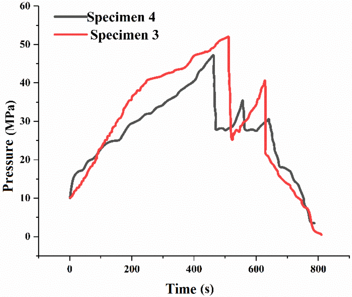
Figure 13: Pump pressure vs. time curves for Specimen 3 and Specimen 4 during SC-CO2 fracturing
Figs. 14 and 15 show the acoustic emission (AE) test results for Specimens 3 and 4, respectively. In the experiment on Specimen 3, the localized AE events are concentrated on three distinct planes, one of which intersects with the other two. For Specimen 4, AE events are distributed across multiple intersecting planes, indicating that supercritical CO2 fracturing leads to the formation of both horizontal and vertical fractures. The AE localization results are consistent with the observed macroscopic fracture patterns in the specimens. Similar to hydraulic fracturing with water, the SC-CO2 fracturing experiments also exhibit a large number of shear failure events, along with the occurrence of tensile failure. Table 3 further compares the experimental results of hydraulic fracturing using low-viscosity slickwater and supercritical carbon dioxide.
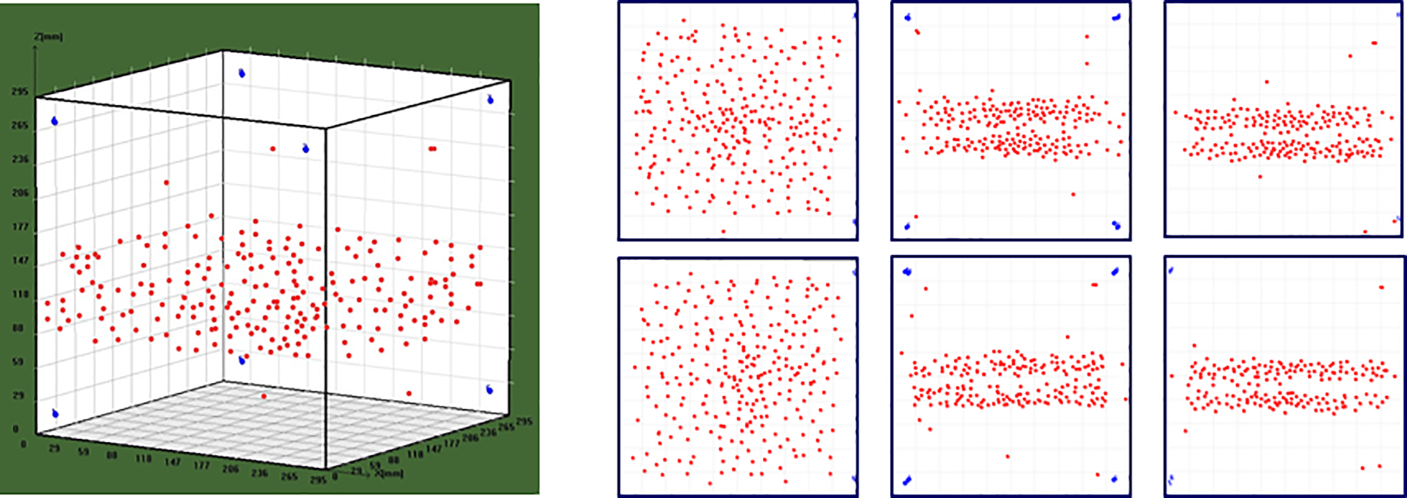
Figure 14: Acoustic emission test results of Specimen 3
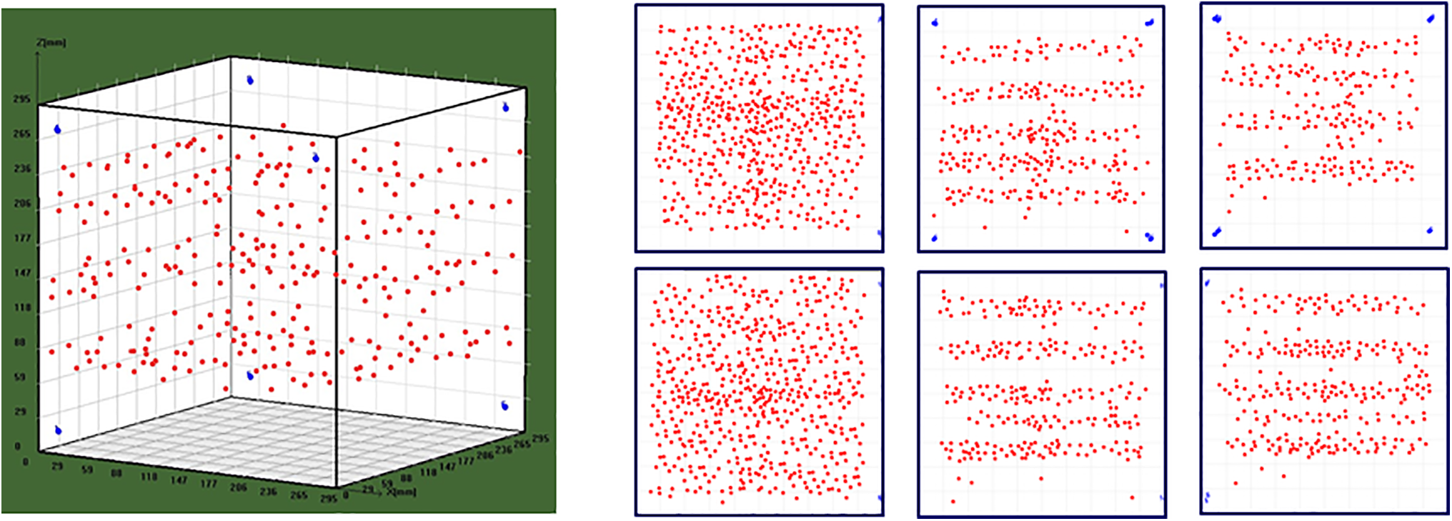
Figure 15: Acoustic emission test results of Specimen 4
(1) True triaxial physical simulation experiments are conducted on outcrop shale samples from the target area under different fracturing fluid conditions. Under identical experimental conditions, supercritical CO2 fracturing shows a significantly lower fracture initiation pressure compared to water-based hydraulic fracturing. This outcome is primarily attributed to the following factors: (1) Supercritical CO2, formed under specific temperature and pressure conditions, exists in a state between gas and liquid. It possesses low viscosity and high diffusivity, allowing it to flow more easily through fractures and exhibit lower wettability than water. These characteristics reduce the pressure required to drive fluid into fractures. (2) The small molecular size and high diffusivity of CO2 enhance its ability to penetrate micropores and microcracks, enabling more efficient fracture propagation at lower pressures. (3) Chemical interactions between CO2 and rock minerals may alter local mechanical properties, weakening the rock structure and promoting fracture initiation and growth under reduced external stress [38]. (4) Elevated injection temperatures and pressures associated with SC-CO2 introduce thermal stress, which further reduces rock strength and facilitates fracture propagation.
(2) In addition to lower initiation pressure, fractures generated by SC-CO2 tend to be more complex than those formed during water-based fracturing. This can be explained by the following: (1) Extremely low viscosity allows SC-CO2 to infiltrate fine fractures and rapidly diffuse throughout the formation, contributing to the development of intricate fracture networks. (2) Chemical reactions between CO2 and mineral surfaces can weaken specific regions, making them more susceptible to fracturing. (3) Low surface wettability reduces fluid retention, promoting more continuous and extensive fracture propagation. (4) Altered local stress distribution, particularly the reduction in effective stress, lowers the rock’s shear strength and facilitates crack growth. (5) Thermal effects during CO2 injection induce stress changes that further aid in crack initiation and propagation.
Acknowledgement: Not applicable.
Funding Statement: The authors received no specific funding for this study.
Author Contributions: The authors confirm contribution to the paper as follows: Conceptualization, Gang Chen; methodology, Taizhi Shen; writing—original draft preparation, Dan Zhang; writing—review and editing, Jiang Bai. All authors reviewed the results and approved the final version of the manuscript.
Availability of Data and Materials: Data available on request from the authors.
Ethics Approval: Not applicable.
Conflicts of Interest: The authors declare no conflicts of interest to report regarding the present study.
References
1. Clarkson CR, Jensen JL, Chipperfield S. Unconventional gas reservoir evaluation: what do we have to consider? J Nat Gas Sci Eng. 2012;8(2):9–33. doi:10.1016/j.jngse.2012.01.001. [Google Scholar] [CrossRef]
2. Zhang DX, Yang TY. Environmental impacts of hydraulic fracturing in shale gas development in the United States. Pet Explor Dev. 2015;42(6):801–7. (In Chinese). doi:10.1016/s1876-3804(15)30085-9. [Google Scholar] [CrossRef]
3. Wu P, Wang Y, Fu L, Chen Y, Wang Y, Zhang Z, et al. Exploration and practice of one trip technology for deep shale gas horizontal wells. Pet Mach. 2023;51(8):26–33. (In Chinese). [Google Scholar]
4. Goodman A, Sanguinito S, Kutchko B, Natesakhawat S, Cvetic P, Allen AJ. Shale pore alteration: potential implications for hydrocarbon extraction and CO2 storage. Fuel. 2020;265:116930. doi:10.1016/j.fuel.2019.116930. [Google Scholar] [PubMed] [CrossRef]
5. Vengosh A, Jackson RB, Warner N, Darrah TH, Kondash A. A critical review of the risks to water resources from unconventional shale gas development and hydraulic fracturing in the United States. Environ Sci Technol. 2014;48(15):8334–48. doi:10.1021/es405118y. [Google Scholar] [PubMed] [CrossRef]
6. Galkin S, Savitckii I, Shustov D, Kukhtinskii A, Osovetsky B, Votinov A. Modeling of crack development associated with proppant hydraulic fracturing in a clay-carbonate oil deposit. Fluid Dyn Mater Process. 2023;19(2):273–84. doi:10.32604/fdmp.2022.021697. [Google Scholar] [CrossRef]
7. Muhammed NS, Olayiwola T, Elkatatny S. A review on clay chemistry, characterization and shale inhibitors for water-based drilling fluids. J Pet Sci Eng. 2021;206:109043. doi:10.1016/j.petrol.2021.109043. [Google Scholar] [CrossRef]
8. Ahmed S, Sri Hanamertani A, Rehan Hashmet M. CO2 foam as an improved fracturing fluid system for unconventional reservoir. In: Exploitation of unconventional oil and gas resources-hydraulic fracturing and other recovery and assessment techniques. London, UK: IntechOpen; 2019. doi:10.5772/intechopen.84564. [Google Scholar] [CrossRef]
9. Memon S, Feng R, Ali M, Bhatti MA, Giwelli A, Keshavarz A, et al. Supercritical CO2-Shale interaction induced natural fracture closure: implications for SC-CO2 hydraulic fracturing in shales. Fuel. 2022;313(4):122682. doi:10.1016/j.fuel.2021.122682. [Google Scholar] [CrossRef]
10. Han L, Shi X, Ni H, Zhang W, Gao Q. Review of CO2 fracturing and carbon storage in shale reservoirs. Energy Fuels. 2024;38(17):15913–34. doi:10.1021/acs.energyfuels.4c01887. [Google Scholar] [CrossRef]
11. Yang Y, Luo Y, Peng B, Cheng J, Ye S. Analysis of fluid-structure interaction during fracturing with supercritical CO2. Fluid Dyn Mater Process. 2024;20(12):2887–906. doi:10.32604/fdmp.2024.057056. [Google Scholar] [CrossRef]
12. Zhang X, Song X, Li X, Liu S, Wang J, Wei J, et al. Supercritical CO2 injection-induced fracturing in Longmaxi shales: a laboratory study. Energies. 2025;18(4):855. doi:10.3390/en18040855. [Google Scholar] [CrossRef]
13. Hazarika S, Boruah A. Supercritical CO2 (SCO2) as alternative to water for shale reservoir fracturing. Mater Today Proc. 2022;50(20):1754–7. doi:10.1016/j.matpr.2021.09.187. [Google Scholar] [CrossRef]
14. Andersen PØ, Brattekås B, Zhou Y, Nadeau P, Nermoen A, Yu Z, et al. Carbon capture utilization and storage (CCUS) in tight gas and oil reservoirs. J Nat Gas Sci Eng. 2020;81(6):103458. doi:10.1016/j.jngse.2020.103458. [Google Scholar] [CrossRef]
15. Kalam S, Afagwu C, Al Jaberi J, Siddig OM, Tariq Z, Mahmoud M, et al. A review on non-aqueous fracturing techniques in unconventional reservoirs. J Nat Gas Sci Eng. 2021;95:104223. doi:10.1016/j.jngse.2021.104223. [Google Scholar] [CrossRef]
16. Zhou D, Zhang G, Prasad M, Wang P. The effects of temperature on supercritical CO2 induced fracture: an experimental study. Fuel. 2019;247(3):126–34. doi:10.1016/j.fuel.2019.02.099. [Google Scholar] [CrossRef]
17. Verdon JP, Kendall JM, Maxwell SC. A comparison of passive seismic monitoring of fracture stimulation from water and CO2 injection. Geophysics. 2010;75(3):MA1–7. doi:10.1190/1.3377789. [Google Scholar] [CrossRef]
18. Ishida T, Nagaya Y, Inui S, Aoyagi K, Nara Y, Chen Y, et al. AE monitoring of hydraulic fracturing experiments conducted using CO2 and water. In: Rock mechanics for resources, energy and environment. Boca Raton, FL, USA: CRC Press; 2013. p. 957–62. doi:10.1201/b15683-165. [Google Scholar] [CrossRef]
19. Li X, Feng Z, Han G, Elsworth D, Marone C, Saffer D, et al. Breakdown pressure and fracture surface morphology of hydraulic fracturing in shale with H2O, CO2 and N2. Geomech Geophys Geo Energy Geo Resour. 2016;2(2):63–76. doi:10.1007/s40948-016-0022-6. [Google Scholar] [CrossRef]
20. Zhang X, Lu Y, Tang J, Zhou Z, Liao Y. Experimental study on fracture initiation and propagation in shale using supercritical carbon dioxide fracturing. Fuel. 2017;190:370–8. doi:10.1016/j.fuel.2016.10.120. [Google Scholar] [CrossRef]
21. Wang L, Yao B, Xie H, Winterfeld PH, Kneafsey TJ, Yin X, et al. CO2 injection-induced fracturing in naturally fractured shale rocks. Energy. 2017;139(1):1094–110. doi:10.1016/j.energy.2017.08.031. [Google Scholar] [CrossRef]
22. Hu Y, Liu F, Hu Y, Kang Y, Chen H, Liu J. Propagation characteristics of supercritical carbon dioxide induced fractures under true tri-axial stresses. Energies. 2019;12(22):4229. doi:10.3390/en12224229. [Google Scholar] [CrossRef]
23. Isaka BLA, Ranjith PG, Rathnaweera TD, Wanniarachchi WAM, Kumari WGP, Haque A. Testing the frackability of granite using supercritical carbon dioxide: insights into geothermal energy systems. J CO2 Util. 2019;34(1):180–97. doi:10.1016/j.jcou.2019.06.009. [Google Scholar] [CrossRef]
24. He J, Zhang Y, Li X, Wan X. Experimental investigation on the fractures induced by hydraulic fracturing using freshwater and supercritical CO2 in shale under uniaxial stress. Rock Mech Rock Eng. 2019;52(10):3585–96. doi:10.1007/s00603-019-01820-w. [Google Scholar] [CrossRef]
25. Al Shafloot T, Kim TW, Kovscek AR. Investigating fracture propagation characteristics in shale using SC-CO2 and water with the aid of X-ray computed tomography. J Nat Gas Sci Eng. 2021;92(B6):103736. doi:10.1016/j.jngse.2020.103736. [Google Scholar] [CrossRef]
26. Hu H, Wang B, Wang X, Zhang Q, Chen Y, Liang Q, et al. Comparative analysis of the fracturing effect of H2O, liquid CO2, and supercritical CO2 on tight sandstone reservoir. In: Proceedings of the 16th Greenhouse Gas Control Technologies Conference (GHGT-16); 2022 Oct 23–27; Lyon, France. doi:10.2139/ssrn.4273068. [Google Scholar] [CrossRef]
27. Li SH, Xing HL, Jin GD, Zhang SC, Zou YS. Experimental study on fracture propagation during supercritical CO2 fracturing in layered tight sandstone reservoirs. In: 57th U.S. Rock Mechanics/Geomechanics Symposium; 2023 Jun 25–28; Atlanta, GA, USA. doi:10.56952/arma-2023-0692. [Google Scholar] [CrossRef]
28. Feng Y, Firoozabadi A. Phase-field simulation of hydraulic fracturing by CO2 and water with consideration of thermoporoelasticity. Rock Mech Rock Eng. 2023;56(10):7333–55. doi:10.1007/s00603-023-03355-7. [Google Scholar] [CrossRef]
29. Jiang Y, Qin C, Kang Z, Zhou J, Li Y, Liu H, et al. Experimental study of supercritical CO2 fracturing on initiation pressure and fracture propagation in shale under different triaxial stress conditions. J Nat Gas Sci Eng. 2018;55(S2):382–94. doi:10.1016/j.jngse.2018.04.022. [Google Scholar] [CrossRef]
30. Zou Y, Li N, Ma X, Zhang S, Li S. Experimental study on the growth behavior of supercritical CO2-induced fractures in a layered tight sandstone formation. J Nat Gas Sci Eng. 2018;49(3):145–56. doi:10.1016/j.jngse.2017.11.005. [Google Scholar] [CrossRef]
31. Thiercelin MJ, Ben-Naceur K, Lemanczyk ZR. Simulation of three-dimensional propagation of a vertical hydraulic fracture. In: SPE Rocky Mountain Petroleum Technology Conference/Low-Permeability Reservoirs Symposium; 1985 May 19–22; Denver, CO, USA. doi:10.2118/13861-ms. [Google Scholar] [CrossRef]
32. Hou B, Chen M, Li ZM, Wang YH, Diao C. Propagation area evaluation of hydraulic fracture networks in shale gas reservoirs. Pet Explor Dev. 2014;41(6):763–8. (In Chinese). doi:10.1016/s1876-3804(14)60101-4. [Google Scholar] [CrossRef]
33. Clifton RJ, Abou-Sayed AS. On the computation of the three-dimensional geometry of hydraulic fractures. In: SPE Ro In: SPE Rocky Mountain Petroleum Technology Conference/Low-Permeability Reservoirs Symposium; 1979 May 20–22;Denver, CO, USA. doi:10.2118/7943-ms. [Google Scholar] [CrossRef]
34. Guo T, Zhang S, Qu Z, Zhou T, Xiao Y, Gao J. Experimental study of hydraulic fracturing for shale by stimulated reservoir volume. Fuel. 2014;128(10):373–80. doi:10.1016/j.fuel.2014.03.029. [Google Scholar] [CrossRef]
35. Williams M. Radial filtration of drilling muds. Trans AIME. 1940;136(1):57–70. [Google Scholar]
36. Rothman RL, Greenfield RJ, Hardy HR Jr. Errors in hypocenter location due to velocity anisotropy. Bull Seismol Soc Am. 1974;64(6):1993–6. doi:10.1785/bssa0640061993. [Google Scholar] [CrossRef]
37. Ishida T, Sasaki S. Numerical simulation to examine accuracy of AE source location and its applications to in situ rock monitoring. J Acoust Emiss. 2011;29:260–72. [Google Scholar]
38. Yu Q. Effect of CO2 immersion on mechanical properties of shale rock [dissertation]. Chengdu, China: Southwest Petroleum University; 2022. (In Chinese). [Google Scholar]
Cite This Article
 Copyright © 2025 The Author(s). Published by Tech Science Press.
This work is licensed under a Creative Commons Attribution 4.0 International License , which permits unrestricted use, distribution, and reproduction in any medium, provided the original work is properly cited.
 Downloads
 Citation Tools