
 Submit a Paper
 Propose a Special lssue
 Open Access
ARTICLE

Optimized Foil-Based Impeller Design for Enhanced Power Recovery in Pump-as-Turbine Applications
1 Department of Aerospace, University Putra Malaysia (UPM), Serdang, 43400, Selangor, Malaysia
2 Department of Mechanical and Manufacturing Engineering, University Putra Malaysia (UPM), Serdang, 43400, Selangor, Malaysia
* Corresponding Author: Ali Abdulshaheed. Email:
Fluid Dynamics & Materials Processing 2025, 21(9), 2289-2304. https://doi.org/10.32604/fdmp.2025.066983
Received 22 April 2025; Accepted 07 August 2025; Issue published 30 September 2025
 View Full Text
 Download PDF
Abstract
A pump operating as a turbine (PAT) is a type of hydraulic machine capable of functioning both as a pump and as a turbine by reversing the flow direction. The pump-as-turbine (PAT) approach presents an effective method of hydropower generation, particularly suitable for addressing the increasing global energy demands in rural and remote areas. In addition to its adaptability, PAT-based micro-hydropower systems typically incur lower operating costs than conventional hydrodynamic turbines, despite requiring higher initial investment. Recent research has focused on integrating PATs into pipe distribution systems to harness untapped hydraulic energy. This study presents the development and performance evaluation of a novel pump operating as a turbine (PAT) impeller, designed to enhance hydropower recovery in water distribution systems. A three-dimensional (3D) impeller model was created using Catia software, integrating airfoil (hydrofoil) geometries into the blade profile to improve the efficiency of power extraction during turbine operation. Unlike conventional designs, the new impeller configuration generates additional force components aligned with the rotor’s direction of rotation, thereby increasing the moment about the axis and enhancing angular velocity. Computational fluid dynamics (CFD) simulations performed in ANSYS Fluent confirmed that the redesigned PAT significantly improves both performance and efficiency, demonstrating superior power recovery compared to the original design. The results highlight the potential of integrating PAT systems with optimized blade geometries into water distribution networks, offering a viable solution for energy recovery and head reduction during periods of low demand.Keywords
In the present context of rising energy demands and escalating environmental pollution caused by fossil fuel consumption, a transition to hydropower energy is increasingly recognized as a viable and sustainable solution [1,2]. Pump-as-turbine (PAT) systems are considered compact and environmentally friendly hydropower generators. A key advantage of PAT systems lies in their low installation and maintenance costs. Furthermore, these small-scale, eco-friendly hydropower pumps can mitigate energy shortages in off-grid regions and support emergency operations during flood events. A cost analysis conducted in a specific case study highlighted the growing interest in designing pumps for turbine mode operation [3,4]. The growing demand for water necessitates effective methods for detecting leaks in underground distribution systems. One key strategy for minimizing leakage risk is the reduction of pressure within the pipes [5,6]. The broad applicability of cpump-as-turbine (PAT) systems, along with their ability to function under downstream residual pressure, makes them particularly well-suited for in-pipe energy recovery in existing water infrastructure networks [7,8]. Recent research efforts have concentrated on enhancing the mechanical power output of PAT. Emphasis has been placed on optimizing PAT performance by modifying geometric parameters to maximize energy extraction. For example, [9,10] found that increasing the blade thickness could improve power extraction by 1–3%, owing to a reduced fluid flow rate and an increased inlet head value. Additionally, turbine efficiency is influenced by PAT diameter, with a direct correlation observed between impeller diameter and overall PAT efficiency [1,11]. Studies by [12,13] further revealed that the optimal blade wrap angle of PAT impellers tends to decrease with increasing specific speed. In other advanced approaches, some researchers employed a non-uniform B-spline curve to parameterize the blade profile using a combination of backpropagation neural networks and genetic algorithms [14,15]. In [16], a PAT configuration with four distinct impeller outlet angles was examined, with results indicating that optimal performance was achieved at an outlet angle of 45°. Multi-objective optimization techniques have also been applied to PAT impeller geometry, including the adjustment of twisting, bowing, and sweeping characteristics. A focus on the high-pressure side of the blade yielded performance improvements of 1.17% in pump mode and 0.46% in turbine mode [17]. Additionally, two impeller redesign strategies were proposed to enhance efficiency: (i) a gradient-based optimization algorithm integrated with a 3D Navier-Stokes flow solver, and (ii) a global optimization approach using genetic algorithms and artificial neural networks combined with the same solver. These studies demonstrated the effectiveness of gradient-based methods in optimizing three-dimensional radial turbomachinery blades [18]. One notable design utilizes a spherical lift turbine that applies hydrofoil specifications to improve efficiency, designed for integration into water pipelines and inspired by marine rotor principles. The design of Lucid Energy turbines draws upon blade geometries from Darrieus and Gorlov (H-egg) turbines. In a related advancement, refs. [19,20] improved the rotor of a Savonius hydropower turbine by implementing the S1048 aerofoil section. The following equations provide a theoretical framework for the analysis of forces generated through the implementation of aerofoils.
Equations for foil force values [21,22].
The present study introduces a newly developed three-dimensional (3D) impeller design for a PAT, incorporating airfoil specifications using Catia software. The objective is to enhance the amount of power extracted from the Seri Aman pipe distribution system during periods of low water consumption. Boundary conditions for head and flow rate were obtained in collaboration with Puncak Niaga Water Company, Malaysia. The power extracted by both the original and newly developed PAT models was validated against theoretical calculations. The redesigned PAT impeller was imported into ANSYS Fluent software for simulation, focusing on power extraction at the pump’s best efficiency point (BEP). The simulation results were then compared with those of the original impeller. Findings indicate an increase in power output resulting from the implementation of the newly developed impeller design.
2 New 3D Model of the Impeller Design
The newly developed 3D impeller design aims to maximize energy extraction from water flow by enhancing the conversion of hydraulic energy into mechanical energy at the PAT shaft. When coupled with an electric generator, this mechanical energy can be effectively converted into electricity. The 3D PAT model was developed using Catia software. The software’s parallel curve tool was utilized to apply foil dimensions to various planes of the PAT impeller, as illustrated in the algorithm below. The hydrofoil dimensions and specifications were sourced from a specialized foil database. Table 1 provides the corresponding parametric values. The parameter c represents the foil chord length, defined as the straight line connecting the leading edge (LD) to the trailing edge (TD).
Table 1: The original pump’s design specifications value.
| Impeller Design Dimensions | Impeller Design Parameters | Value | Unit |
|---|---|---|---|
| Inlet main flow angle | α1 | 90° | degree |
| Inlet impeller relative angle value | β1 | 18° | degree |
| Shroud impeller diameter | Dshroud | 120 | mm |
| Outlet impeller diameter | D2 | 250 | mm |
| Outlet main flow angle | α2 | 7.6° | degree |
| Outlet impeller relative angle value | β2 | 9.5° | degree |
| Impeller speed | N | 1450 | rpm |
| Pump Flowrate | Q | 60 | m3/h |
| Pump head | H | 20 | m |
| Shaft inner Diameter | Dshaft | 30 | mm |
| Shaft outer Diameter | Dhub | 40 | mm |
| Outer width of blade | b2 | 17.3 | mm |
| Number of impeller blade | Z | 6 | ˗ |
Algorithm 1 used to generate foil at any plane in Catia Program:
| Algorithm 1: Algorithm used to generate foil at any plane in Catia software parallel curve option |
| If (x < xf) yc = f ∗ c/100 ∗ (1/(xf2)) ∗ (2 ∗ xf ∗ x − x2) Else Yc = f ∗ c/100 ∗ (1/((1 − xf)2)) ∗ ((1 − 2 ∗ xf) + 2 ∗ xf ∗ x − x2) yt = 5 ∗ t ∗ c/100(0.2969 ∗ x0.5 − 0.1260 ∗ x − 0.3516 ∗ x2 + 0.2843 ∗ x3 − 0.1015 ∗ x4) |
The final 3D model of the new impeller design is illustrated in Fig. 1 below.
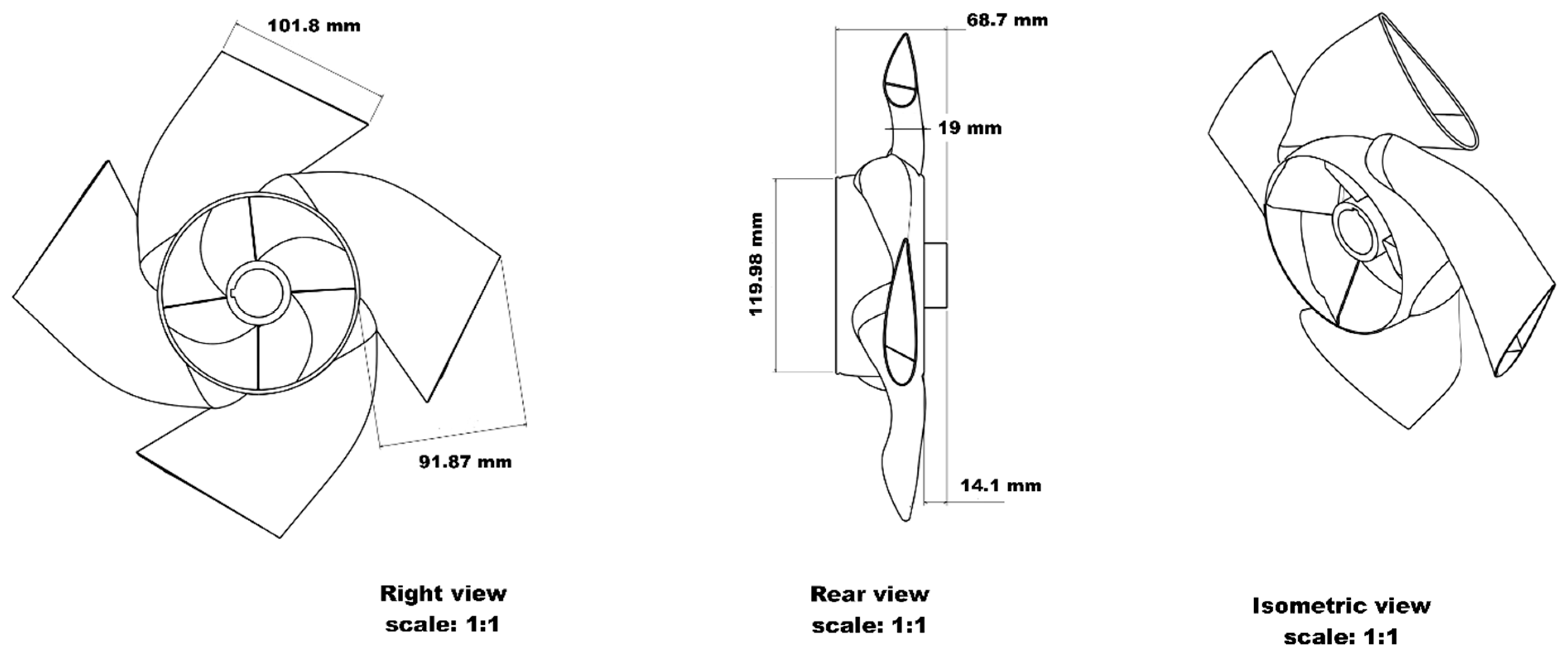
Figure 1: 3D model of the new impeller design.
2.1 Foil Specifications in the 3D Model of the New Impeller Design
To enhance power extraction from fluid flow and facilitate the conversion of kinetic energy into mechanical energy, hydrofoil specifications were incorporated into the 3D design of the new impeller. The application of hydrofoil specifications introduces additional force components beyond those present in the original design. These specifications were obtained from a publicly available hydrofoil database, specifically using the NACA 4-digit series. The four digits in the NACA code correspond to defined parametric values that influence hydrodynamic characteristics. Variations in these parameters directly affect the lift-to-drag ratio (CL/CD), thereby influencing the overall performance. The allocation of hydrofoil parameters and the design construction process are depicted in Fig. 2.
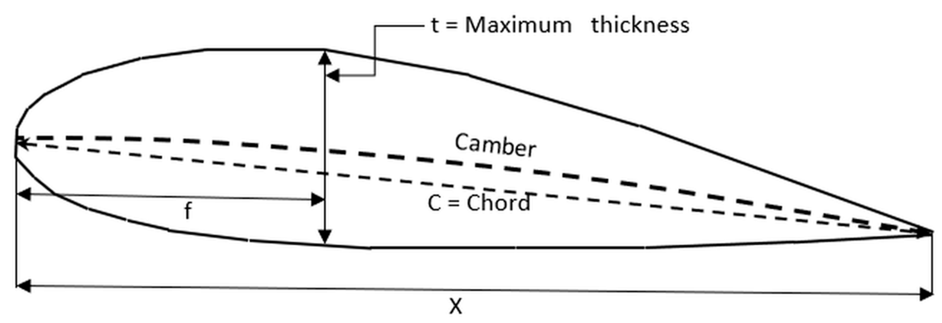
Figure 2: Four-digit foil parameters.
In accordance with the design requirements, the hydrofoil parametric values were selected to align with the original dimensions of the impeller vanes, as shown in Fig. 3.
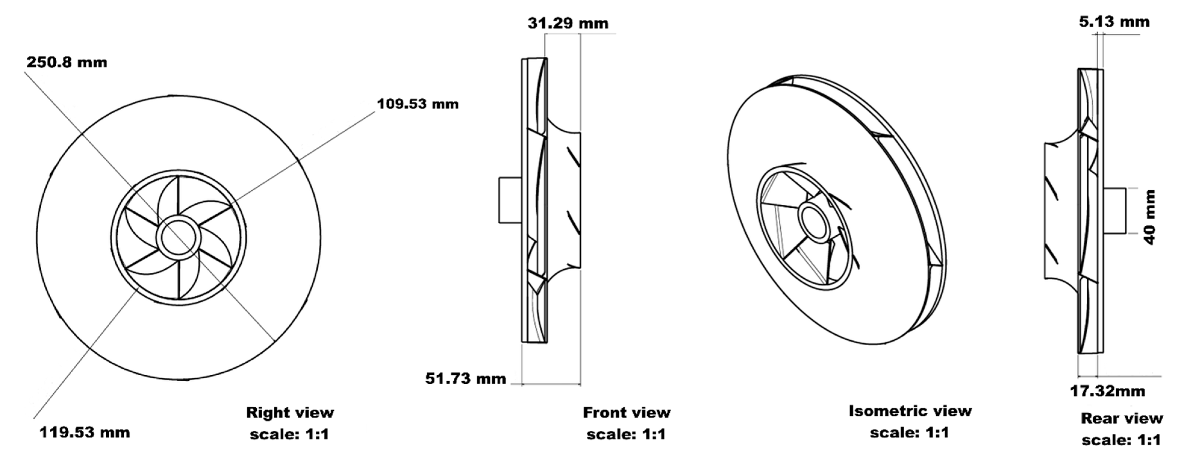
Figure 3: The original pump impeller’s dimensions.
The original pump design specifications are presented in Table 1.
For the new design, the selected NACA foil was 2418, and its corresponding parametric values are listed in Table 2.
Table 2: The foil’s four digits values (NACA) representing its parametric values.
| No. | NACA Value | Nomenclature | Foil Parameters Specification |
|---|---|---|---|
| 1. | 2 | f | Maximum Gamber value |
| 2. | 4/100 | xf | Position of maximum Gamber |
| 3. | 18 | t | Thickness of Foil |
The 3D impeller model was developed in Catia using the Generative Shape Design module to create the impeller’s body surfaces. The final impeller model consisted of an assembly of multiple solid geometrical components. A comparative model analysis between the original and newly developed pump impeller designs is illustrated in Fig. 4 and Fig. 5.

Figure 4: New pump’s impeller design models.
The new PAT model design incorporates changes to the shroud and hub features of the original rotor, while the blade dimensions consider the foundation of the forthcoming design.

Figure 5: Original pump’s impeller design models.
The original rotor blade dimensions impose restrictive criteria for the design. The list of the hydrofoil implementation restrictions for the new design model is as follows. The chord length relative to the maximum foil thickness (t) was determined based on the width at inlet of the PAT’s rotor blade, was 17.32 mm as explained in Fig. 3. The ratio between the hydrofoil chord length at the inlet diameter of PAT and the chord length at the outlet diameter needs to be compatible with Catia software standards to ensure proper hydrofoil geometry edge sharpness, exceeding sharpness criteria could prevent solid geometry generation led to fail import model in ANSYS software. The blade’s hydrofoil geometry must be assembled in such a way that it does not intersect at the outlet diameter of the PAT’s. Therefore, the PAT’s rotor blades number was reduced from 6 (PAT’s original rotor) to 4.
2.2 Centrifugal Pump Volute (Case) Design Model
The volute, or casing, is the second critical component of a centrifugal pump. It functions as the housing that encases the impeller. As the impeller rotates, it imparts energy to the fluid within the volute (Fig. 6). The fluid enters through the inlet and is discharged to the pumping system via the outlet. The angle between the inlet and outlet is set at 90°, and the volute diameter gradually increases towards the outlet. This design facilitates the conversion of kinetic energy into pressure energy. Conversely, when the pump operates in reverse as a turbine (PAT mode), the fluid enters from the pump outlet and flows toward the inlet, as illustrated in Fig. 7.
The fundamental design principle of the volute is illustrated in Eq. (3), where
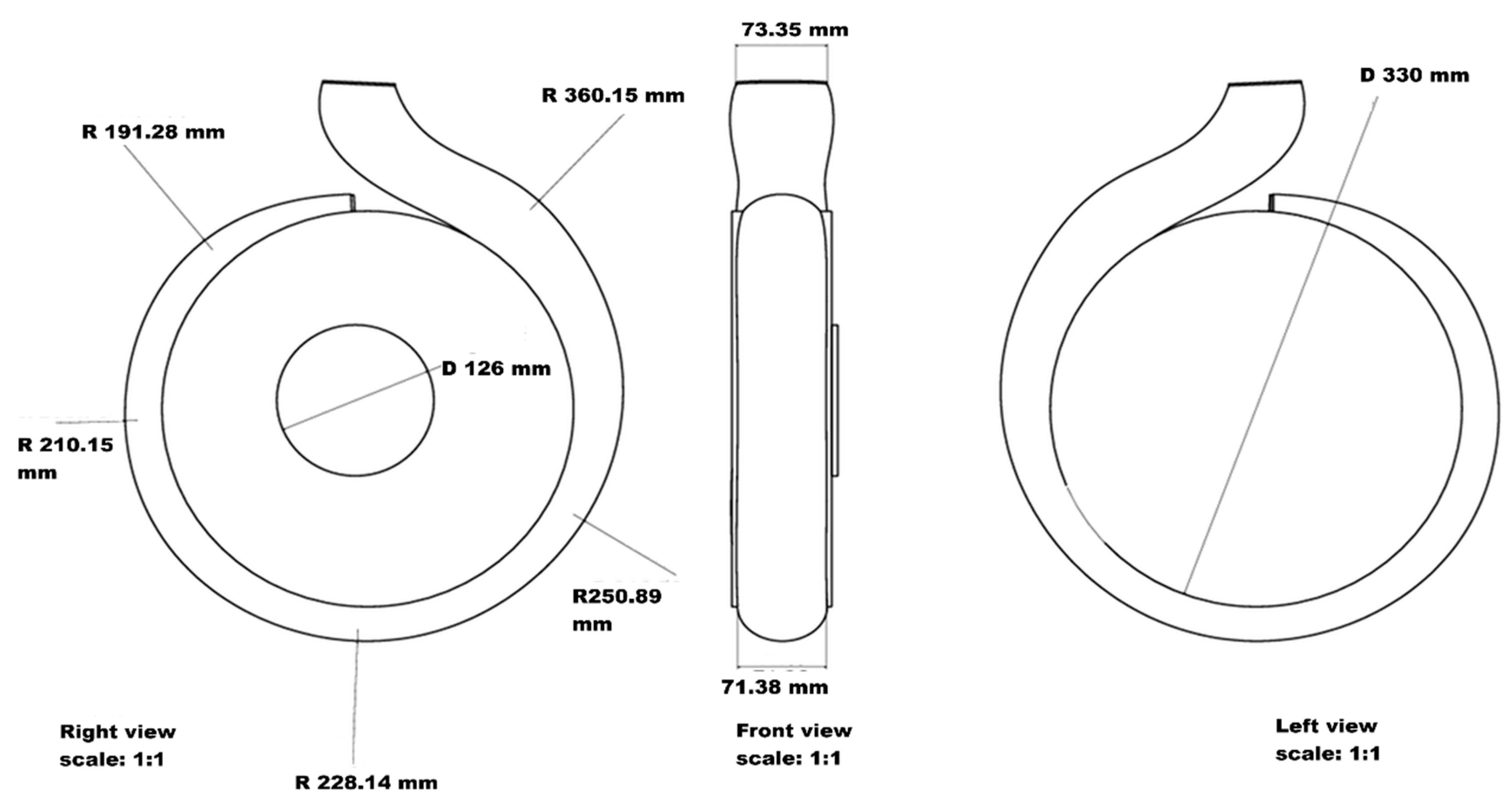
Figure 6: Pump’s volute model dimensions.
The volute and impeller were assembled upon import into ANSYS Student 2023 software to simulate the pump operating in reverse as a turbine (PAT). In this configuration, the fluid flow direction is reversed—from the pump’s outlet to its inlet—as illustrated in Fig. 7.

Figure 7: The pump’s volute imported to the Ansys software, working as a turbine (PAT).
3 Numerical Simulation Setup in the ANSYS Software
The 3D PAT model was initially developed using Catia V5 software. The objective of the new PAT design is to optimize the amount of power extracted as fluid passes through the redesigned impeller, functioning as a turbine. The model incorporates foil specifications to enhance power extraction by improving efficiency during reverse operation. The new impeller model was subsequently imported into ANSYS Fluent as a 3D geometry. Due to the geometric complexity of the new design and the absence of predefined rotor parameters (e.g., moment and angular velocity), a transient solver setup was employed. The angular velocity of the PAT rotor is determined using the momentum equation, where it equals the product of angular velocity and moment of inertia. The transferred momentum was the difference between the inlet and outlet fluid momentum passed through the PAT rotor, while the moment of inertia indicates the resistance to rotor movement around an axis (Fig. 8).
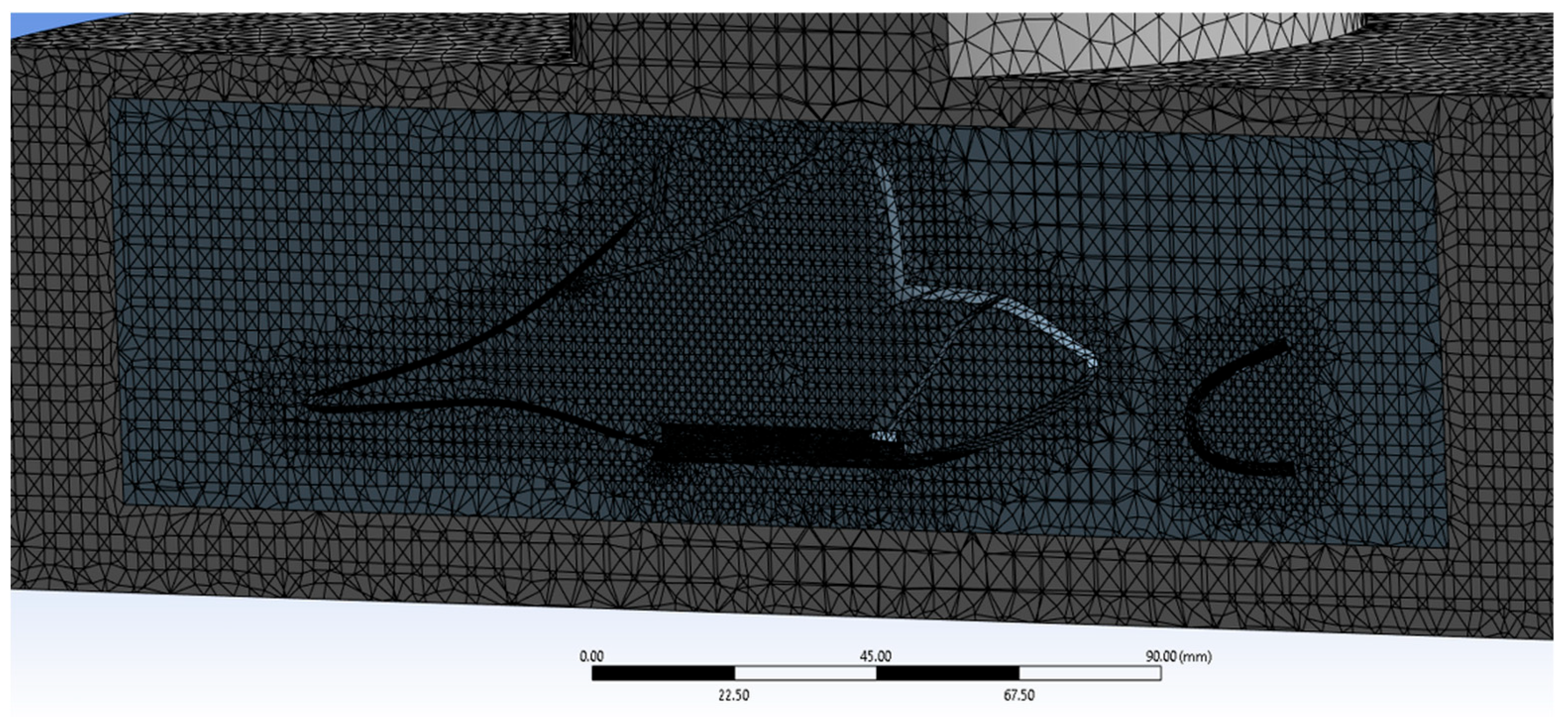
Figure 8: New PAT rotor design mesh method.
3.1 Computational Domain Selection and Meshing
A new geometry design was imported after it was established in Catia software. A combination of meshing methods was explored, and the final mesh configuration used a tetrahedral, patch-independent technique. The mesh consisted of 3,520,000 elements, the volute comprised of 1,520,000 mesh elements, and the rotor zone was 2,000,000 mesh elements, with a maximum skewness of 0.93. The dimensionless y+ value for PAT model 4.13, the rotor value was 0.9 and the value at volute equal to 6.67. The meshed model for the new PAT rotor is depicted in Fig. 8.
3.2 Mesh Independence Verification
Various mesh sizes and methods were employed to generate mesh regions (volute and rotate) for the PAT model. An independent mesh test was performed to ensure robust numerical calculations, correlating mesh element sizes with variations in output power values. The numerical results are presented in Fig. 9.
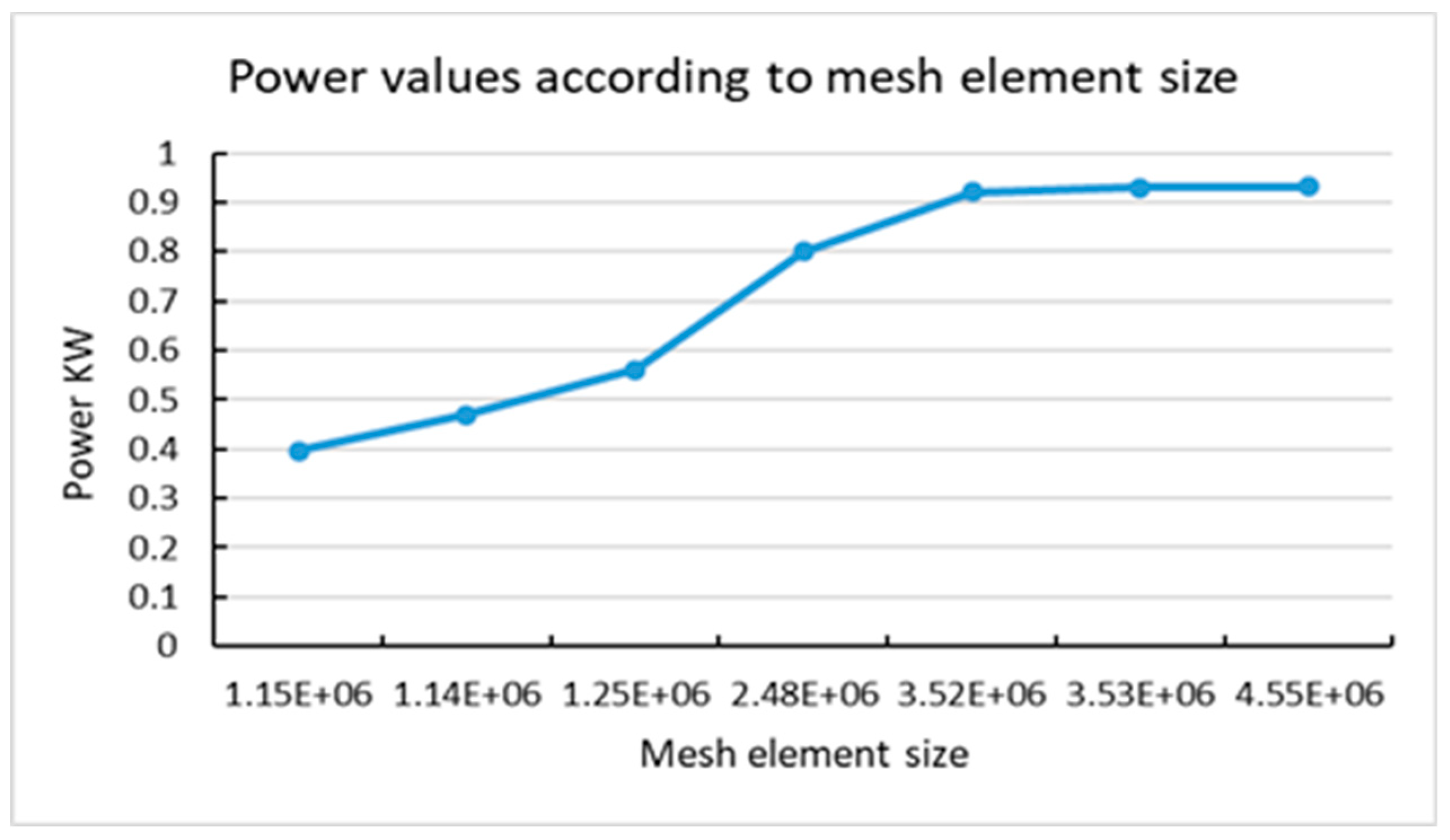
Figure 9: Output power with different model mesh sizes.
3.3 Turbulence Model and Boundary Condition Setting
The simulation was conducted using a transient solver with the SST k-omega turbulence model used in numerical calculation in relevant literature [23,24]. Boundary conditions for PAT were velocity inlet, pressure outlet, and standard wall function for wall [25]. Turbulent kinetic energy and specific dissipation rate were computed using the discrete calculation scheme, employing the second order upwind method. The pressure–based is used to represent the pressure-velocity scheme coupling, the pressure numerical scheme set to SIMPLE algorithm [26], achieving residual convergence (set at 10−5) considering the model’s complexity and the use of a dynamic mesh approach. The numerical scheme calculation accuracy involves simulating results for every 4° rotation of the PAT’s impeller at each time step [26,27].
A dynamic mesh with the 6 Degrees of Freedom (6 DOF) setting was employed to simulate rotor motion and to evaluate the conversion of fluid energy into mechanical shaft energy [28]. This mechanical power is intended to be transfered to the PAT shaft, which can be coupled with an electrical generator for energy conversion.
The extracted power was calculated using Eq. (7), which multiplies torque by angular velocity. To ensure consistency and enable comparative analysis, the same ANSYS Fluent simulation parameters were applied for both the original and the newly developed PAT rotor designs.
The new impeller design was utilized to increase power harvested from the water distribution system, the purpose was to compare the power extracted by new and original rotor designs. The power extracted shows enhancement when the new rotor design was conducted (Fig. 10 and Fig. 11).

Figure 10: PAT velocity values for the new rotor design.

Figure 11: PAT velocity values for the original rotor design.
A comparative analysis of the power extraction values between the original and the new rotor designs is illustrated in Fig. 12. The results indicate that the new PAT rotor design significantly improves power extraction under identical boundary conditions (flow rate and head). This improvement suggests greater efficiency in energy transfer and demonstrates the enhanced performance of the redesigned PAT system. The observed improvement is primarily attributed to increased force components acting on the new rotor blades. The introduction of foil-based lift forces contributes to a higher moment around the rotor axis, thereby increasing the power output. The distribution of these force components is illustrated in Fig. 13.
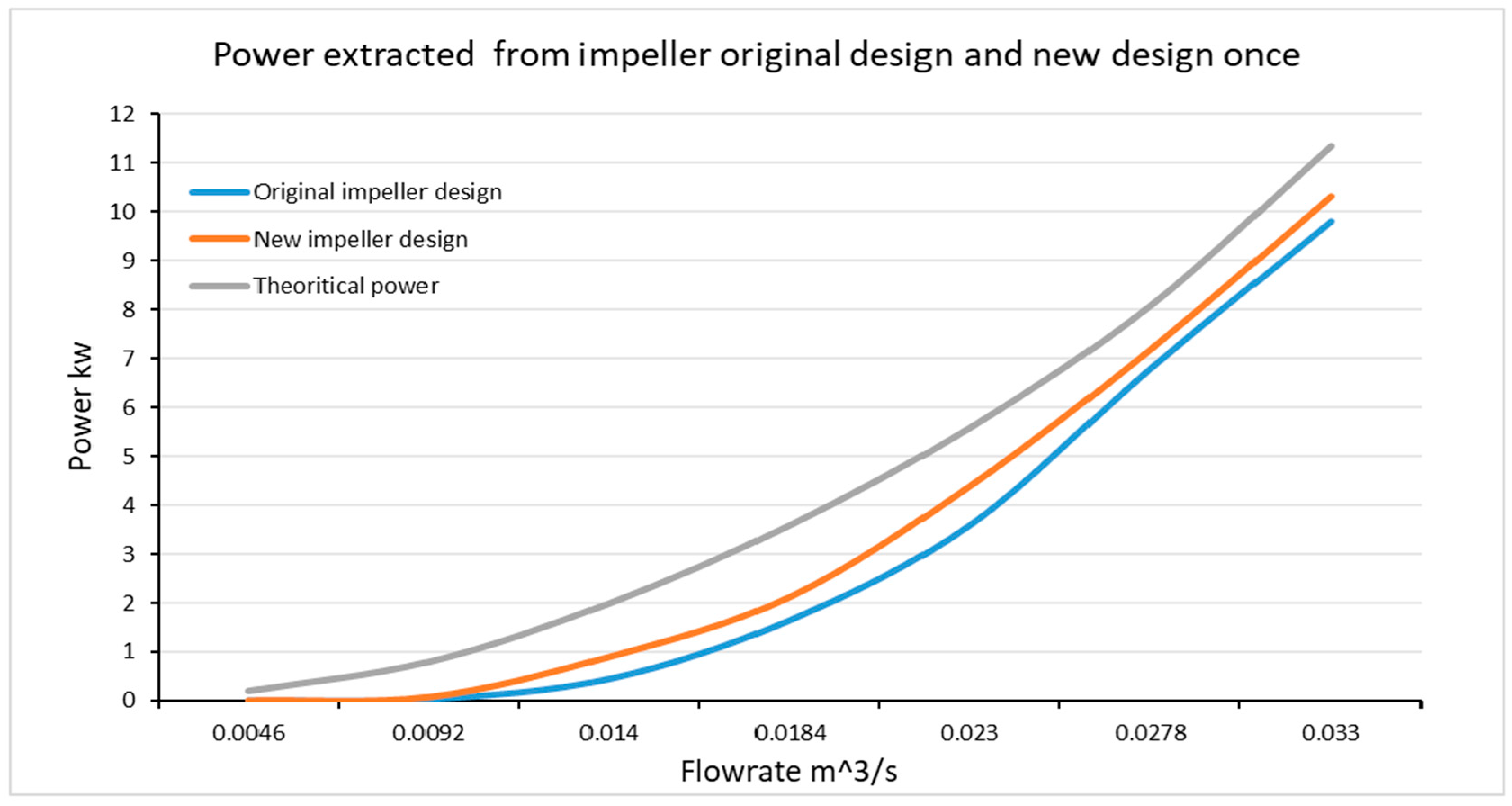
Figure 12: Power extraction comparison between the original PAT rotor and the new design rotor.
The implementation of foil specifications in the new rotor design introduces additional force components generated as the foil moves horizontally or rotates about its axis. These forces arise due to the velocity differential between the upper and lower surfaces of the foil, resulting in hydrodynamic lift (Fn) and drag (FD) forces, as described by Eqs. (1) and (2). The lift force, a key feature of hydrofoil behavior, has been integrated into the new PAT impeller design. This new impeller accumulates both the original hydraulic forces and the newly generated hydrodynamic forces, thereby enhancing the mechanical power output. The lift force generated is a function of fluid density, the lift coefficient, foil chord length, and fluid velocity. In contrast, the drag force acts in the direction opposite to the impeller’s rotation and may reduce the net mechanical power output. As part of the new PAT rotor (impeller) configuration, the number of blades was reduced from six (in the original design) to four. This modification was necessitated by the dimensional requirements of the new design. Specifically, the outlet width of the new blade design was increased due to a corresponding increase in the rotor’s volumetric dimensions. The fluid velocity value reduced in the new design rotor due to the change in the volumetric parameter and geometry complexity (angle blockage), as illustrated in Fig. 1 and Fig. 3. The velocity is concentrated on the outside impeller shroud with a larger surface area than the inner impeller blade Fig. 10, resulting in increased generated force in the new impeller design than the original as explained Eq. (1). Instead, increasing in the extracted moment maximizes the output PAT power value according to Eq. (7) in Section 3. As depicted in Fig. 10 and Fig. 11, the increase in blade volume resulted in a reduction in fluid velocity through the rotor, consistent with the design’s intent to optimize power extraction while minimizing flow resistance.
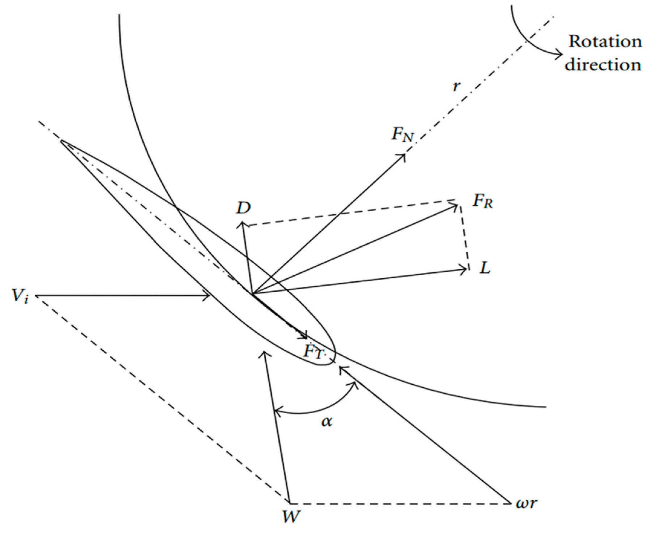
Figure 13: Foil force components on the new rotor design.
Power extracted using PAT was compared with power data from literature based on flowrate and pressure values. Results were compared with experimental data as reported in [29] and PAT simulation outcomes outlined in [30]. The results, shown in Fig. 14, demonstrate convergence and validate the accuracy of the procedure.
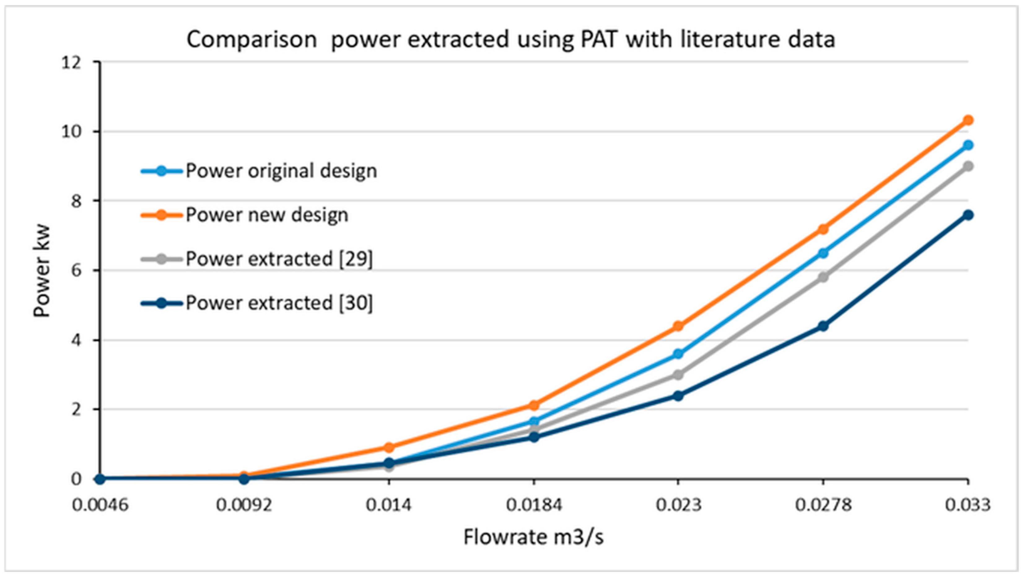
Figure 14: Comparison between extracted power by PAT with literature data [29,30].
The PAT was designed to extract energy from the Seri Aman water distribution system. The system’s 24-h head and flow rate data were obtained through collaboration with the Puncak Niaga water company, as illustrated in Fig. 15. Analysis of this data reveals that the maximum head values occur between 1:00 a.m. and 7:30 a.m., a period associated with low water demand from consumers. To mitigate the risk of pipe leaks, it is essential to reduce excessive head during these low-demand hours. The PAT functions by converting potential hydraulic energy into mechanical energy, which can be used to generate electricity, particularly during emergencies. Both the original and the newly designed PAT rotor models were implemented to harness potential energy from the Seri Aman water distribution system during the high-head period of low water consumption, between 1:00 a.m. and 7:30 a.m.
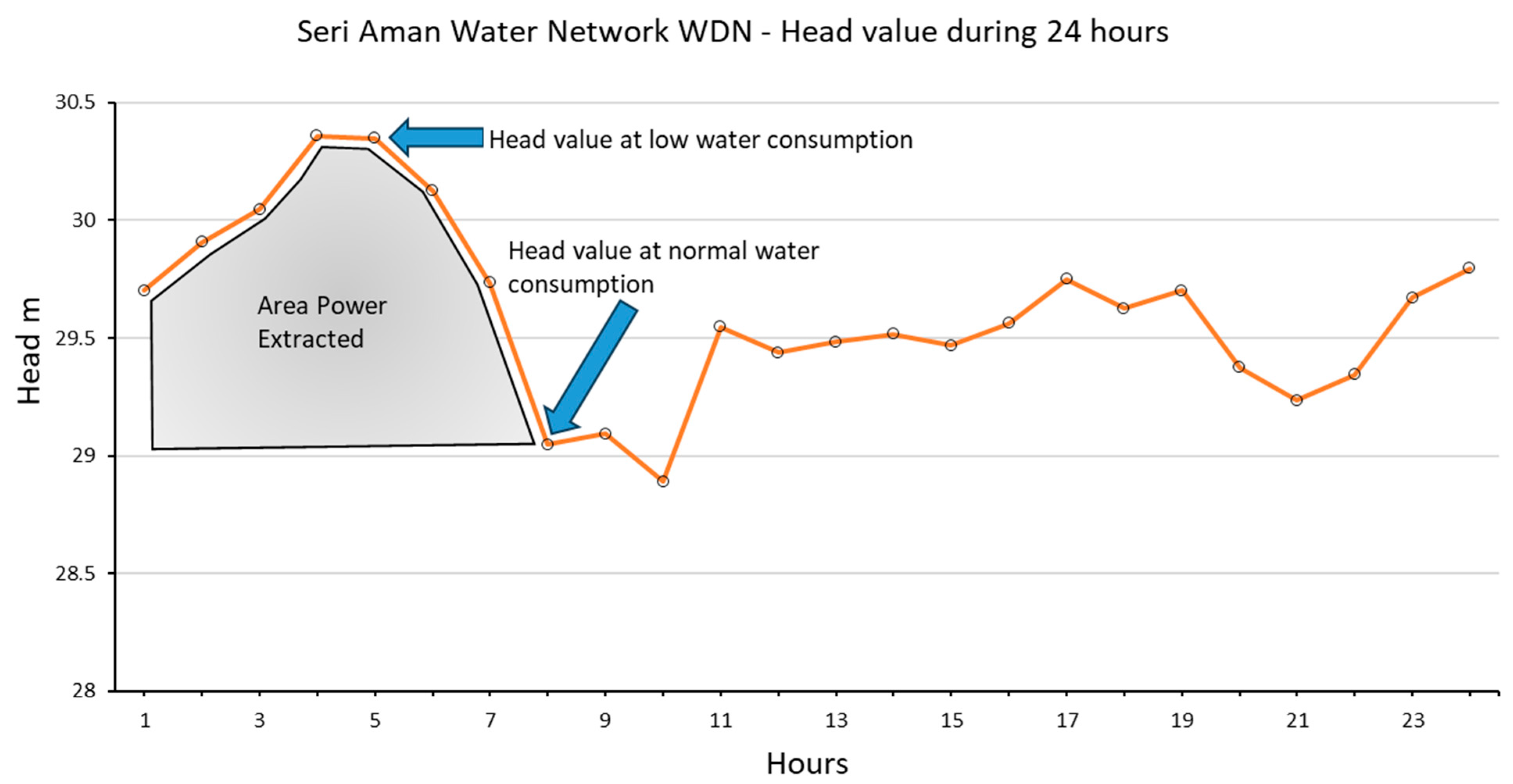
Figure 15: 24-h head values taken from the Puncak Niaga water company.
The power extraction results are presented in Fig. 16. The extracted power varied in response to fluctuations in head and flow rate. The highest head values, and consequently the greatest energy extraction potential, were recorded between 4:00 a.m. and 5:00 a.m. The extracted power from both the original and the new PAT rotor designs was validated using theoretical power calculations.
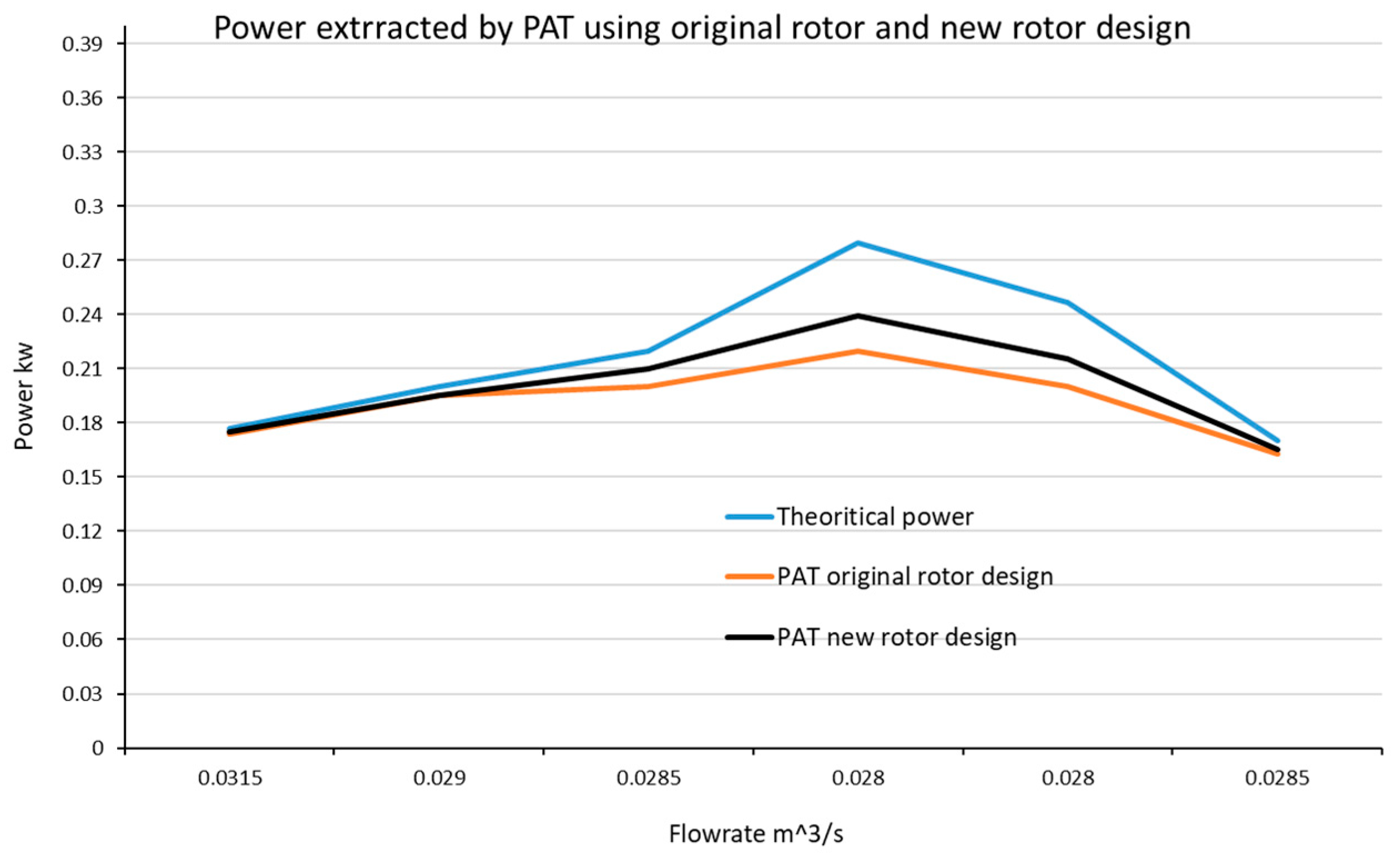
Figure 16: Power extraction values from using the PAT original rotor and new rotor designs.
The efficiency of power extraction from the pipe distribution system is strongly influenced by head values during low water consumption periods. These findings highlight the correlation between system head and the likelihood of leakage, reinforcing the benefits of controlled head reduction via PAT deployment. Moreover, the results demonstrate improved power harvesting with the new PAT rotor design, likely due to the hydrodynamic enhancements at the rotor’s outer edge following the implementation of foil specifications, as depicted in Fig. 13 and Fig. 15.
The present study investigated the performance of a pump operating in reverse flow, functioning as a turbine (PAT). The hydrofoil specifications were incorporated into the design of a new impeller to enhance PAT efficiency by maximizing the hydropower extracted and subsequently converted into mechanical energy. The new blade design was developed using Catia software, while power extraction simulations were conducted using ANSYS Fluent. The simulation results demonstrate that the new PAT model significantly improves both performance and efficiency, as shown in Fig. 13 and Fig. 16.
The improved hydropower extraction is attributed to the implementation of hydrofoil specifications, which generate additional force components around the PAT rotor axis aligned with the direction of rotation. In contrast, the original PAT impeller design does not facilitate such force generation. The presence of these additional force components increases the moment around the rotor axis, which, in turn, enhances angular velocity. This increase in angular velocity contributes to higher electrical power output derived from mechanical energy conversion.
Acknowledgement:
Funding Statement: The authors received no specific funding for this study.
Author Contributions: Ali Abdulshaheed: Writing—review & editing, Writing—original draft, Visualization, Validation, Software, Methodology, Investigation, Formal analysis, Data curation, Conceptualization. Faizal Mustapha: Supervision, Methodology, Investigation. Mohd Anuar: Validation, Software, Methodology. All authors reviewed the results and approved the final version of the manuscript.
Availability of Data and Materials: The datasets generated and/or analyzed during the current study are available from the corresponding author on reasonable request.
Ethics Approval: Not applicable.
Conflicts of Interest: The authors declare no conflicts of interest to report regarding the present study.
Nomenclature
| Power, kW | |
| Moment, N·m | |
| Angular velocity, Rad/s | |
| Theoretical velocity, m/s | |
| Velocity coefficient | |
| Theoretical flowrate, m3/s | |
| Suction diameter of pump, mm | |
| Delivery diameter of pump, mm | |
| Theoretical diameter of volute output, mm | |
| Fluid density, kg/m3 | |
| Foil chord, mm | |
| Drag coefficient | |
| Lift coefficient | |
| Maximum Camber value | |
| Position of maximum Camber | |
| Thickness of Foil |
References
1. Yu H, Wang T, Dong Y, Gou Q, Lei L, Liu Y. Numerical investigation of splitter blades on the performance of a forward-curved impeller used in a pump as turbine. Ocean Eng. 2023;281:114721. doi:10.1016/j.oceaneng.2023.114721. [Google Scholar] [CrossRef]
2. Jemal AN, Haile MG. Comprehensive review of pump as turbine. Ren Ener Sust Dev. 2019;5(2):68. doi:10.21622/resd.2019.05.2.068. [Google Scholar] [CrossRef]
3. Lydon T, Coughlan P, McNabola A. Pump-As-turbine: characterization as an energy recovery device for the water distribution network. J Hydraul Eng. 2017;143(8):04017020. doi:10.1061/(asce)hy.1943-7900.0001316. [Google Scholar] [CrossRef]
4. Rossi M, Nigro A, Renzi M. Experimental and numerical assessment of a methodology for performance prediction of Pumps-as-Turbines (PaTs) operating in off-design conditions. Appl Energy. 2019;248:555–66. doi:10.1016/j.apenergy.2019.04.123. [Google Scholar] [CrossRef]
5. Abdulshaheed A, Mustapha F, Anuar M. Pipe material effect on water network leak detection using a pressure residual vector method. J Water Resour Plann Manage. 2018;144(4):05018006. doi:10.1061/(asce)wr.1943-5452.0000798. [Google Scholar] [CrossRef]
6. Wang X, Zhang K, Bai X, Miao S, Wu Z, Li J. Optimization of a pipeline-type savonius hydraulic turbine. Fluid Dyn Mater Process. 2024;20(5):1123–46. doi:10.32604/fdmp.2023.043272. [Google Scholar] [CrossRef]
7. Caxaria GA, de Mesquita e Sousa D, Ramos HM. Small scale hydropower: generator analysis and optimization for water supply systems. In: Proceedings of the World Renewable Energy Congress 2011—Sweden; 2011 May 8–13; Linköping, Sweden. doi:10.3384/ecp110571386. [Google Scholar] [CrossRef]
8. Carravetta A, Fecarotta O, Ramos HM. A new low-cost installation scheme of PATs for pico-hydropower to recover energy in residential areas. Renew Energy. 2018;125:1003–14. doi:10.1016/j.renene.2018.02.132. [Google Scholar] [CrossRef]
9. Liu M, Tan L, Cao S. Performance prediction and geometry optimization for application of pump as turbine: a review. Front Energy Res. 2022;9:818118. doi:10.3389/fenrg.2021.818118. [Google Scholar] [CrossRef]
10. Yang SS, Wang C, Chen K, Yuan X. Research on blade thickness influencing pump as turbine. Adv Mech Eng. 2014;6:190530. doi:10.1155/2014/190530. [Google Scholar] [CrossRef]
11. Stefanizzi M, Filannino D, Capurso T, Camporeale SM, Torresi M. Optimal hydraulic energy harvesting strategy for PaT installation in Water Distribution Networks. Appl Energy. 2023;344:121246. doi:10.1016/j.apenergy.2023.121246. [Google Scholar] [CrossRef]
12. Yang SS, Kong FY, Chen H, Su XH. Effects of blade wrap angle influencing a pump as turbine. J Fluids Eng. 2012;134(6):061102. doi:10.1115/1.4006677. [Google Scholar] [CrossRef]
13. Ghorani MM, Sotoude Haghighi MH, Maleki A, Riasi A. A numerical study on mechanisms of energy dissipation in a pump as turbine (PAT) using entropy generation theory. Renew Energy. 2020;162:1036–53. doi:10.1016/j.renene.2020.08.102. [Google Scholar] [CrossRef]
14. Katrenko M, Borsch V, Kulyk O. Approximation of blades of radial machines with multiparameter family of smooth surfaces. Nauk Visn Nat Hirn Univ. 2022;6:68–75. doi:10.33271/nvngu/2022-6/068. [Google Scholar] [CrossRef]
15. Miao SC, Yang JH, Shi GT, Wang TT. Blade profile optimization of pump as turbine. Adv Mech Eng. 2015;7(9):1687814015605748. doi:10.1177/1687814015605748. [Google Scholar] [CrossRef]
16. Shi HX, Chai LP, Su XZ, Jaini R. Performance optimization of energy recovery device based on PAT with guide vane. Int J Simul Model. 2018;17(3):472–84. doi:10.2507/ijsimm17(3)443. [Google Scholar] [CrossRef]
17. Qin Y, Li D, Wang H, Liu Z, Wei X, Wang X. Multi-objective optimization design on high pressure side of a pump-turbine runner with high efficiency. Renew Energy. 2022;190:103–20. doi:10.1016/j.renene.2022.03.085. [Google Scholar] [CrossRef]
18. Derakhshan S, Mohammadi B, Nourbakhsh A. The comparison of incomplete sensitivities and Genetic algorithms applications in 3D radial turbomachinery blade optimization. Comput Fluids. 2010;39(10):2022–9. doi:10.1016/j.compfluid.2010.07.003. [Google Scholar] [CrossRef]
19. Khan ZU, Ali Z, Uddin E. Performance enhancement of vertical axis hydrokinetic turbine using novel blade profile. Renew Energy. 2022;188:801–18. doi:10.1016/j.renene.2022.02.050. [Google Scholar] [CrossRef]
20. Chen J, Yang HX, Liu CP, Lau CH, Lo M. A novel vertical axis water turbine for power generation from water pipelines. Energy. 2013;54:184–93. doi:10.1016/j.energy.2013.01.064. [Google Scholar] [CrossRef]
21. Wilberforce T, Olabi AG, Sayed ET, Alalmi AH, Ali Abdelkareem M. Wind turbine concepts for domestic wind power generation at low wind quality sites. J Clean Prod. 2023;394:136137. doi:10.1016/j.jclepro.2023.136137. [Google Scholar] [CrossRef]
22. Pope K, Dincer I, Naterer GF. Energy and exergy efficiency comparison of horizontal and vertical axis wind turbines. Renew Energy. 2010;35(9):2102–13. doi:10.1016/j.renene.2010.02.013. [Google Scholar] [CrossRef]
23. Sun Y, Zuo Z, Liu S, Liu J, Wu Y. Distribution of pressure fluctuations in a prototype pump turbine at pump mode. Adv Mech Eng. 2014;6:923937. doi:10.1155/2014/923937. [Google Scholar] [CrossRef]
24. Wang L, Lu J, Liao W, Wang W, Feng J, Zhao Y. Numerical analysis of the formation mechanism and suppression method of the reverse flow in a semi-open centrifugal pump. J Mech Sci Technol. 2020;34(9):3667–78. doi:10.1007/s12206-020-0819-7. [Google Scholar] [CrossRef]
25. Miao S, Yang J, Shi F, Wang X, Shi G. Research on energy conversion characteristic of pump as turbine. Adv Mech Eng. 2018;10(4):1687814018770836. doi:10.1177/1687814018770836. [Google Scholar] [CrossRef]
26. Miao S, Zhang H, Tian W, Li Y. A study on the unsteady flow characteristics and energy conversion in the volute of a pump-as-turbine device. Fluid Dyn Mater Process. 2021;17(5):1021–36. doi:10.32604/fdmp.2021.016925. [Google Scholar] [CrossRef]
27. Lu JL, Guo L, Wang LK, Wang W, Guo PC, Luo XQ. Unsteady flow characteristics of tip clearance in semi-open impeller centrifugal pump. Trans Chin Soc Agric Mach. 2019;50(6):163–72. (In Chinese). [Google Scholar]
28. Chica Arrieta EL, Betancour J, Velásquez L, Rubio Clemente A. Performance simulation of water turbines by using 6-DoF UDF and sliding mesh methods. J Appl Res Technol. 2023;2:181–95. doi:10.22201/icat.24486736e.2023.21.2.1568. [Google Scholar] [CrossRef]
29. Binama M, Su WT, Li XB, Li FC, Wei XZ, An S. Investigation on pump as turbine (PAT) technical aspects for micro hydropower schemes: a state-of-the-art review. Renew Sustain Energy Rev. 2017;79:148–79. doi:10.1016/j.rser.2017.04.071. [Google Scholar] [CrossRef]
30. Liu M, Tan L, Cao S. Theoretical model of energy performance prediction and BEP determination for centrifugal pump as turbine. Energy. 2019;172:712–32. doi:10.1016/j.energy.2019.01.162. [Google Scholar] [CrossRef]
Cite This Article
 Copyright © 2025 The Author(s). Published by Tech Science Press.
This work is licensed under a Creative Commons Attribution 4.0 International License , which permits unrestricted use, distribution, and reproduction in any medium, provided the original work is properly cited.
 Downloads
 Citation Tools