
 Submit a Paper
 Propose a Special lssue
 Open Access
ARTICLE

Coupled Effects of Incident Waves Forcing and Internal Tank Sloshing on the Dynamics of Twin Floating Bodies
1 School of Civil Engineering and Transportation, South China University of Technology, Guangzhou, 510641, China
2 School of Naval Architecture, Ocean & Civil Engineering, Shanghai Jiao Tong University, Shanghai, 200000, China
3 School of Intelligent Manufacturing, Huanghuai University, Zhumadian, 463000, China
* Corresponding Author: Hang Xie. Email:
Fluid Dynamics & Materials Processing 2025, 21(9), 2075-2100. https://doi.org/10.32604/fdmp.2025.069064
Received 13 June 2025; Accepted 12 September 2025; Issue published 30 September 2025
 View Full Text
 Download PDF
Abstract
The growing demand for ocean space has generated significant interest in multi-body floating systems, where gap resonance in confined regions plays a critical role in ensuring the safety of offshore operations. This study develops a numerical tank model using the Smoothed Particle Hydrodynamics (SPH) method, implemented through the open-source code DualSPHysics, to investigate hydrodynamic resonance in a twin-floater system and to examine the influence of internal tank sloshing on its hydrodynamic characteristics. The hydrodynamic behavior of the gap flow between a fixed twin-floater system in the numerical tank is validated through systematic comparison with experimental data. Subsequently, the wave-induced motions and forces on a twin-floater system are compared with those on a single floater. Furthermore, the effects of internal tank sloshing on the hydrodynamic response of the twin-floater system are explored. A parametric study is conducted to analyze the influence of incident wave frequency on floater motion and tank sloshing dynamics. The results show that the presence of an internal tank can significantly reduce pitch motion and vertical forces on the floating body, while exerting minimal influence on heave motion and horizontal forces. The findings provide new insights into the hydrodynamic performance of twin-floater systems and their interaction with internal sloshing phenomena.Keywords
The problems of tank sloshing and multi-floating bodies hydrodynamics are research hotspots in the field of naval architecture and ocean engineering for both academic research and engineering applications. For example, offloading of LNG can be undertaken in a tandem arrangement, where an LNG carrier is moored at the stern of the FLNG vessel [1], or in a side-by-side configuration where the LNG carrier is moored alongside the FLNG vessel. When the moored floating bodies are in restricted water areas, resonance responses of the gap flow or multi-bodies may be induced at specific wave conditions, which can result in a significant increase in the wave dynamic effect or wave height in narrow gap areas. The increase in wave dynamic effect can also increase the motions and wave loads acting on the floating bodies in return. This will pose a threat to the structure strength, collision and operation safety. Therefore, the hydrodynamic disturbance of the multi-floating body structures has received increasing attentions [2].
The research on the hydrodynamics of water wave interaction with multi-bodies has been widely conducted. For example, Saitoh et al. [3] experimentally investigated the fluid resonance effect in the gap between two fixed bodies in a 2D plane. Fredriksen et al. [4] analyzed the dynamic variation of wave height in a narrow gap between two moving boxes by experimental method. Zhu et al. [5] investigated the interaction force of two floating bodies with different gap widths by potential flow theory. However, the potential flow theory tends to overestimate the resonance amplitude at the gap resonant frequency, which is due to the neglect of fluid viscosity and the nonlinear free surface effect. To address this problem, Tan et al. [6] proposed a theoretical dynamic model that includes a linearized damping coefficient, and the obtained numerical result agrees well with that by viscous fluid simulation. Zhang et al. [7] studied the effect of gap width on the flow behavior of 3D fixed double floating bodies using finite difference method of viscous flow theory. Lu et al. [8] investigated the resonance responses in an array of three bodies, and the responses at the two gaps are studied, which is significantly different from the performance in a single gap of twin floating bodies configuration. Similar work can also be found in Sun et al. [9], Jing et al. [10] and Gao et al. [11]. However, in these studies, the multi-bodies are fixed structures, where the radiation problem is not considered, as the wave-induced movement of the structure is not involved.
In fact, many ships and offshore structures are floating structures, and the wave-induced movement of structures affects the flow field in return. Therefore, the interaction of multi-floating bodies and the gap flow resonance is also a reason for concern. He et al. [12] studied the wave-induced fluid resonance in a narrow gap between two rigid-connected boxes that have only one degree of freedom of heave released. Jing et al. [13] further investigated the effects of heave and roll motions on the resonant frequency and amplitude of the gap flow. Sun et al. [14] studied wave-induced free surface motion in the gap between a tanker and an FLNG barge under both fixed and free-floating conditions. Hong et al. [15] experimentally studied the hydrodynamic behavior of Tandem and side-by-side moored vessels of LNG carrier and FLNG in different wave headings. Fang and Chen [16] studied the relative motion and wave elevation in the gap between two ships advancing in waves, and the calculated results are well validated by experimental data. Choi and Hong [17] used a high-order boundary element method to accurately calculate the hydrodynamic interaction between multiple floating bodies, which includes ship motion response and wave drift force. Hong et al. [18] studied the hydrodynamic interaction of side-by-side moored multiple vessels by both numerical and experimental methods. More studies about the gap resonance of double floating bodies can be found in Jing et al. [19], He et al. [20] and Jing et al. [21]. Mohapatra et al. [22] presented a numerical hydrodynamic model for a moored interconnected floating large structure under the action of regular waves to analyze the effect of current and wind. A review of recent developments on the hydroelastic response and gap resonance of multi-body floating structures is presented in Amouzadrad et al. [23].
Moreover, sloshing in the liquid tanks makes the liquid cargo ships’ motion responses much different from the solid loading condition. To date, the coupled response of tank sloshing and floating body motions has been studied by different methods, including potential flow theory [24], CFD simulations [25], SPH simulations [26] and model experiments [27]. Although multi-floating body systems and liquid tank sloshing have been widely investigated, these two problems are usually studied separately. The fully coupled analysis of liquid tank sloshing inside floating bodies in side-by-side configuration is rarely conducted. Jiao et al. [28] simulated two side-by-side LNG ships’ motions coupled with tank sloshing in regular waves by SPH solver. Zhao et al. [29] developed a potential flow theory code to predict the dynamic responses of side-by-side arranged FLNG system, and solved the coupled responses between sloshing in liquid tanks and vessels’ motions in the time domain.
Currently, research on the hydrodynamic interaction problem of twin-floaters with liquid tanks remains quite limited, especially regarding the influence of liquid sloshing in the tanks on the gap flow within the twin-floaters system under multi-degree-of-freedom motions, which awaits further exploration. To better understand the resonance mechanism and response characteristics of twin-floaters under regular waves, this paper conducts a comprehensive study on the hydrodynamic behaviour of simplified floating body of both one- and twin-floater configuration and also with and without tank sloshing. The paper is organized as follows. The basic method of SPH algorithm is described in Section 2, and the applicability of the SPH method in solving the twin-body hydrodynamic problem is also validated by comparing with reference data. In Section 3 the numerical model setup of the twin-floater with tank sloshing involved in this paper is established, and the convergence analysis of time step and particle spacing is conducted. Comparison of responses between one- and twin-floater systems for the cases of without and with internal liquid tank is presented in Section 4. In Section 5, the results are comprehensively compared and analyzed.
2 Basic Theory and Algorithm Validation
This study uses the DualSPHysics open-source software platform, which is on the basis of smooth particle hydrodynamics (SPH) to implement the hydrodynamic simulations. The simulation calculation of the multiphase fluid flow problem is performed via the SPH algorithm of graphics processing unit (GPU) acceleration technology. The basic theory of SPH algorithm is briefly described first. The wave generation and absorption method in the numerical wave tank using the SPH tool is presented. Then the hydrodynamic problems of two fixed boxes and the gap flow resonance phenomenon are simulated by the developed numerical wave tank, and the results are validated by comparing with experimental data in reference.
Using the integral equation on the basis of interpolation function, the conservation law of continuum fluid dynamics is converted into the partial differential form suitable for particle simulation, and an estimated value at a specific point is given. This interpolation or weighting function is usually called the kernel function W, which can be expressed in different forms. The most commonly used form is the cubic or quintic function. It is generally expressed as a function of F(r) defined by r′:
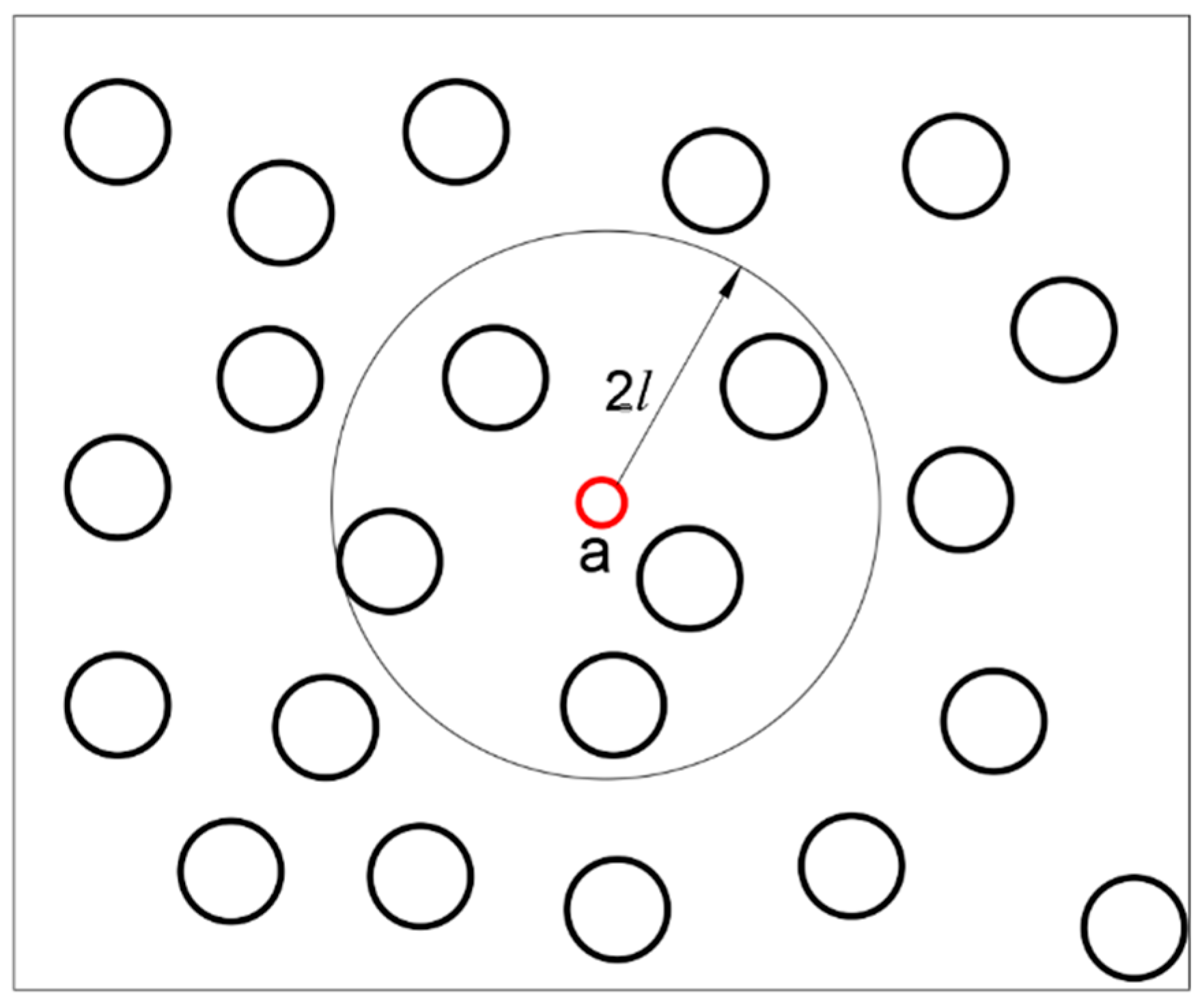
Figure 1: Sketch of the particle integration region.
The performance of the SPH model largely depends on the selection of the smoothing kernel function. In this work, the cubic spline kernel function used in Wendland [30] is as follows:
The equation of momentum conservation in the continuum is as follows:
2.2.1 First Order Wave Generation
The Biesel transfer functions express the relation between wave amplitude and wavemaker displacement, under the assumption of irrotational and incompressible fluid and constant pressure at the free surface in Altomare et al. [36]. The transfer function links the displacement of the piston-type wavemaker to the water surface elevation, under the hypothesis of monochromatic sinusoidal waves in one dimension in the x-direction:
2.2.2 Second-Order Wave Generation of Regular Waves
The Symplectic scheme in Ren and Khayyer [35] is used in the time-stepping algorithm, which is second-order accurate in time and more conducive to wave generation. The implementation of a second-order wavemaker theory will prevent the generation of spurious secondary waves. The second-order wave generation theory implemented in DualSPHysics is based on Madsen [38], who developed a simple second-order wavemaker theory to generate long second-order Stokes waves that would not change shape as they propagated. The theory proposed by Madsen is straightforward, controllable, computationally inexpensive with efficient results, and is accurate for waves of first and second order.
The piston stroke S0 can be redefined from Eq. (14) as S0 = h/m1 where:
Following Madsen [38], to generate a wave of second order, an extra term must be added to Eq. (15). This term, for piston-type wavemaker, is equal to:
Therefore, the piston displacement, for regular waves, is the summation of Eqs. (15) and (17):
A damping zone is implemented in DualSPHysics as passive absorption system. The implemented damping system consists in gradually reducing the velocity of the particles at each time step according to their location, but using quadratic decay rather than exponential. In this way, the velocity is modified following:
2.3 Numerical Method Validation
To validate the SPH numerical method in the simulation of twin-floater hydrodynamics, a numerical model was established that is the same as the experimental model in Saitoh and Miao [3] (see Fig. 2). The 2D numerical tank is 16 m long and 1 m high, and the water depth H = 0.5 m. Regular waves with a predefined wave height h and wave number k are generated by a piston-type maker which is located at the left side of the tank. A damping zone is set behind the floating body at the other end of the tank. For the boundary conditions, an improved adaptive dynamic boundary condition (mDBC) is used on the wall and surface of the numerical tank to avoid defects such as excessive dissipation that may be caused by the traditional dynamic boundary condition (DBC) [39]. The SPH method uses particles to discretely distribute the fluid in the water tank. The push plate moves according to the originally set program. The water particles move accordingly under the action of the push plate, which can visually depict the wave shape at each moment. The entire simulation process is relatively in line with actual cognition and avoids the problems of grid deformation and reconstruction in the wave simulation process of the traditional grid method.
Two fixed boxing bodies are adopted so as to be in consistent with the experimental model in reference. The two fixed bodies have the same geometric size of length L = 0.5 m, depth D = 0.5 m, and draft d = 0.252 m. The width of the narrow gap between the two fixed bodies is set at s = 0.05 m. The fixed body is placed at a distance of 5 m from the wave-maker. Incident waves at different wave number k = 1.2 to 2.4 with a constant wave height h = 0.024 m are generated for study. Two wave probes are used to monitor the waves: Probe 1 is installed at X = 3 m from the wave-maker to monitor the incident wave without disturbance, Probe 2 is placed at X = 5.53 m, which is used to measure the gap flow between the two bodies. The particle spacing of 0.001 m is used in this case.
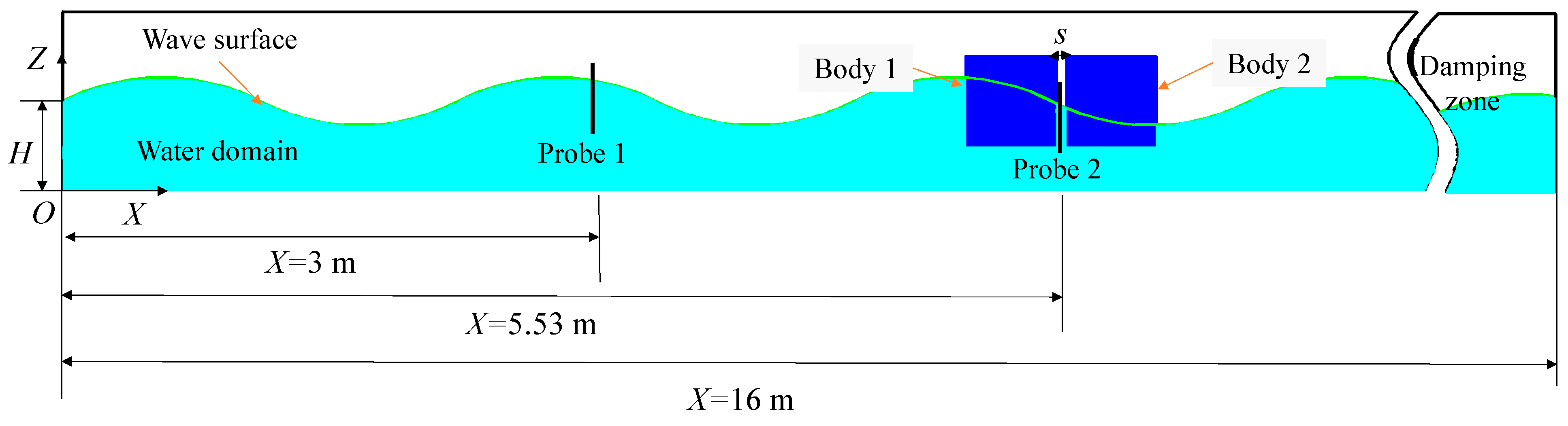
Figure 2: Schematic diagram of the construction of the numerical tank used in the numerical validation.
The case of wave number k = 1.5 and wave height h = 0.2 m is used to illustrate the generated incident waves. Comparison of the time series of wave elevation at Probe 1 in the numerical tank between the monitored and the theoretically expected values is shown in Fig. 3. It shows high consistency between the two curves, which confirms the effectiveness of the numerical wave-making method in this study. The wave height of SPH simulation is 0.11 m, which is 10% larger than the theoretical value of 0.1 m. The wave elevation by SPH simulation shows obvious nonlinear characteristics of sharp crest and flat trough compared with the linear theory wave.
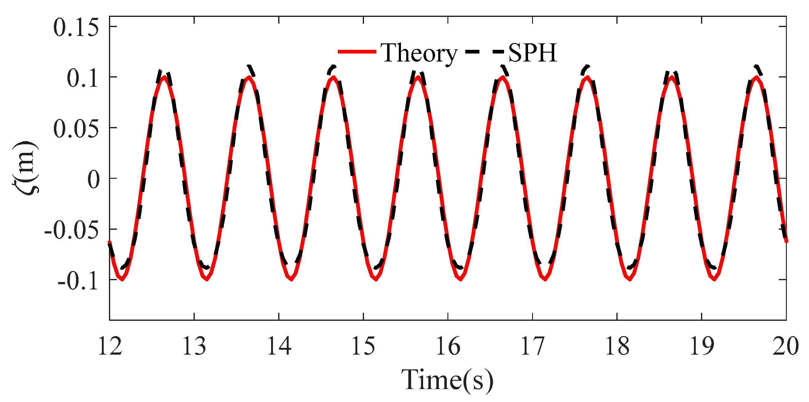
Figure 3: Comparison of time series of wave elevation at Probe 1 (wave number k = 1.5).
The narrow gap flow between the two bodies reveals complex characteristics due to the resonance responses. Fig. 4 shows the ratio of the wave height hD in the narrow gap measured by Probe 2 to the incident wave height h at Probe 1 for the cases of different wave numbers. The results are compared between the present SPH method in this study, the theoretical calculation of Saitoh and Miao [3] and the experimental measurement of Lu and Cheng [8]. Notably, all the results exhibit a significant increase in wave height at narrow gap when the wave number is approximately 1.6, which indicates that a strong resonance phenomenon occurred at or near this wave number. The SPH model used in this study accurately captures this resonance effect, although the obtained wave height at the resonant position is slightly lower than the experimental value (with an error of −6%). The error may be caused by the factor of particle spacing or total number of particles as more accurate flow characteristics can be simulated with smaller particle spacing [37]. When the wave number k tends to 1, the ratio of hD/h tends to 1, which means that long waves have strong transmissivity, and the gap resonance effect becomes weak. However, when the wave number k exceeds 2.5, the ratio of hD/h tends to 0, which means that short waves have weak diffraction and the waves are reflected from the structure body.
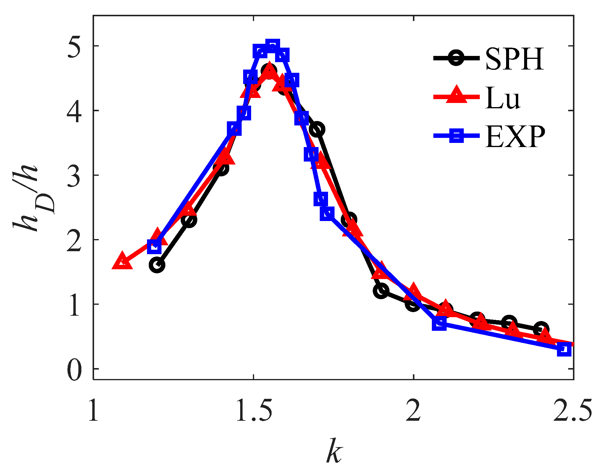
Figure 4: Variations in the wave height in the gap at different wave numbers compared between different methods.
The time series of wave elevation at Probe 2 in the narrow gap under the resonance condition (wave number k = 1.5) is shown in Fig. 5, where the time series of the monitored incident wave at Probe 1 and the theoretical wave amplitude are also presented for comparison. It is seen that the wave height at the narrow gap reaches four times of the incident wave height, which indicates that severe resonant response occurs in the gap flow. The phase of the time series of wave elevation at the two positions is consistent. To further elucidate the mechanism of the resonance, the dynamic variation characteristics of the velocity field in the gap region within one wave period are shown in Fig. 6 for the case of wave number k = 1.5. The fluid velocity in the gap area is greater than the wave field at other area. The wave energy to concentrate on the gap region, thereby promoting an increase in fluid velocity. This increase in the velocity field leads to an increase in the wave height in this region.
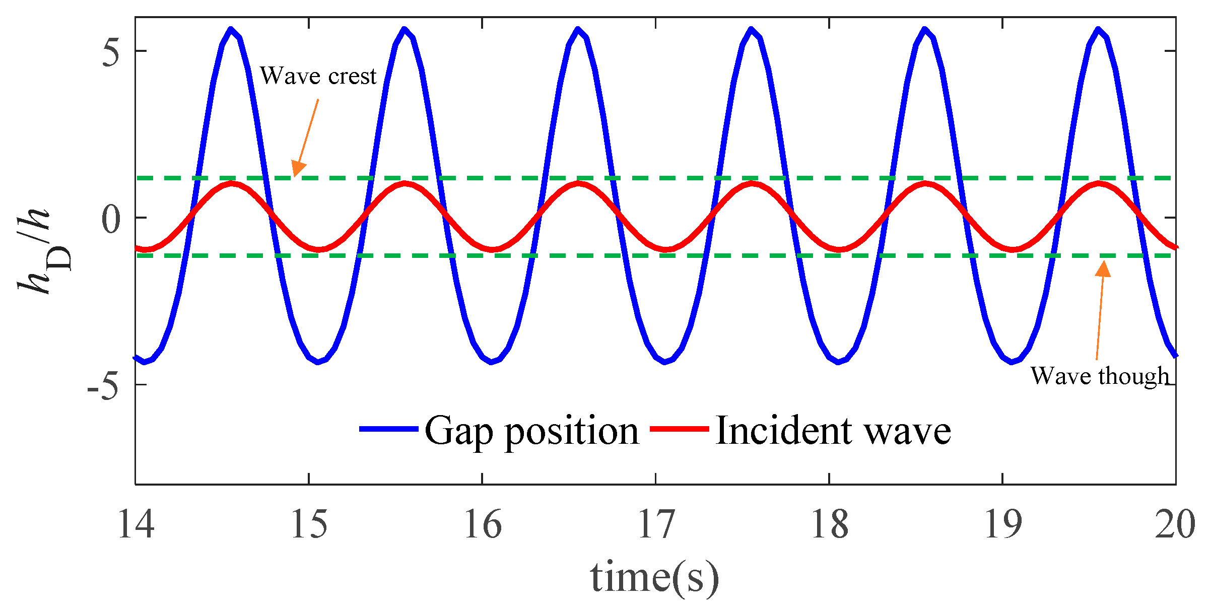
Figure 5: Time series of the wave elevation in the gap and the undistributed incident waves under the resonance wave excitation case (wave number k = 1.5).
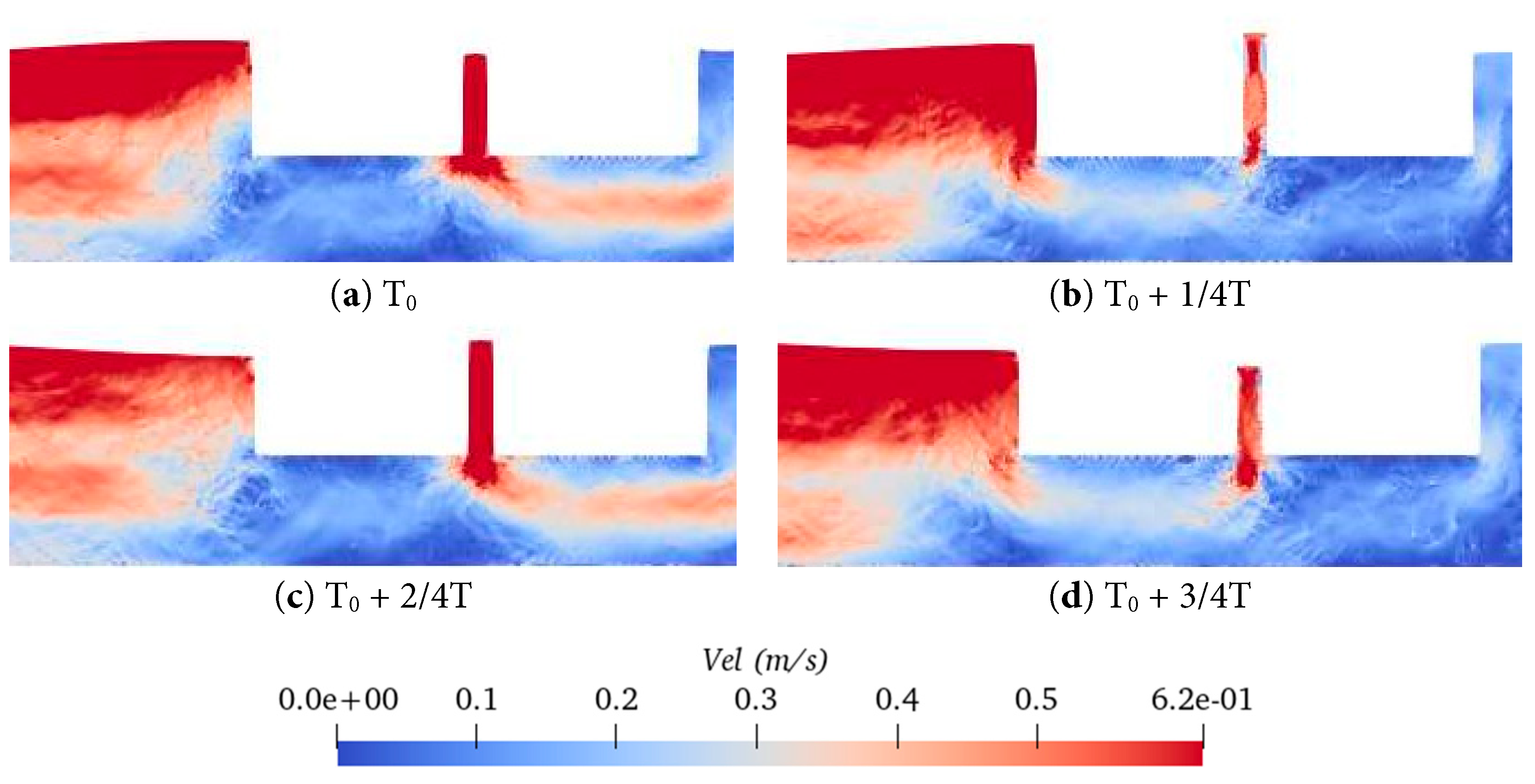
Figure 6: Velocity field distribution in the gap under resonant wave excitation case (T0 = 10 s).
3 Numerical Model Setup of Twin-Floater with Tank
3.1 Model Description and Boundary Conditions
To investigate the hydrodynamic behavior of 2D floating body in regular waves, a 2D numerical wave tank was established, which is shown in Fig. 7. To study the hydrodynamic characteristics of different floating body models, four floating body schemes are adopted: single floater (Scheme 1), twin-floater (Scheme 2), single floater with liquid tank (Scheme 3) and twin-floater with liquid tank (Scheme 4). All the floating bodies in different schemes have the same dimension of length L = 0.5 m by depth B = 0.2 m with draught of T = 0.1 m. For the floating body without liquid tank, a uniform solid model is used, which has an average density of 500 kg/m3 and a pitch moment of inertia of 1.04 kg·m2. For the floating body with liquid tank, it has a cavity structure inside with a wall thickness of 10 mm. The density of the wall structure is 500 kg/m3. The volume of the loaded liquid is half of the whole cavity volume. The fluid inside the tank is water, which has a same density of 1000 kg/m3 with the external fluid.
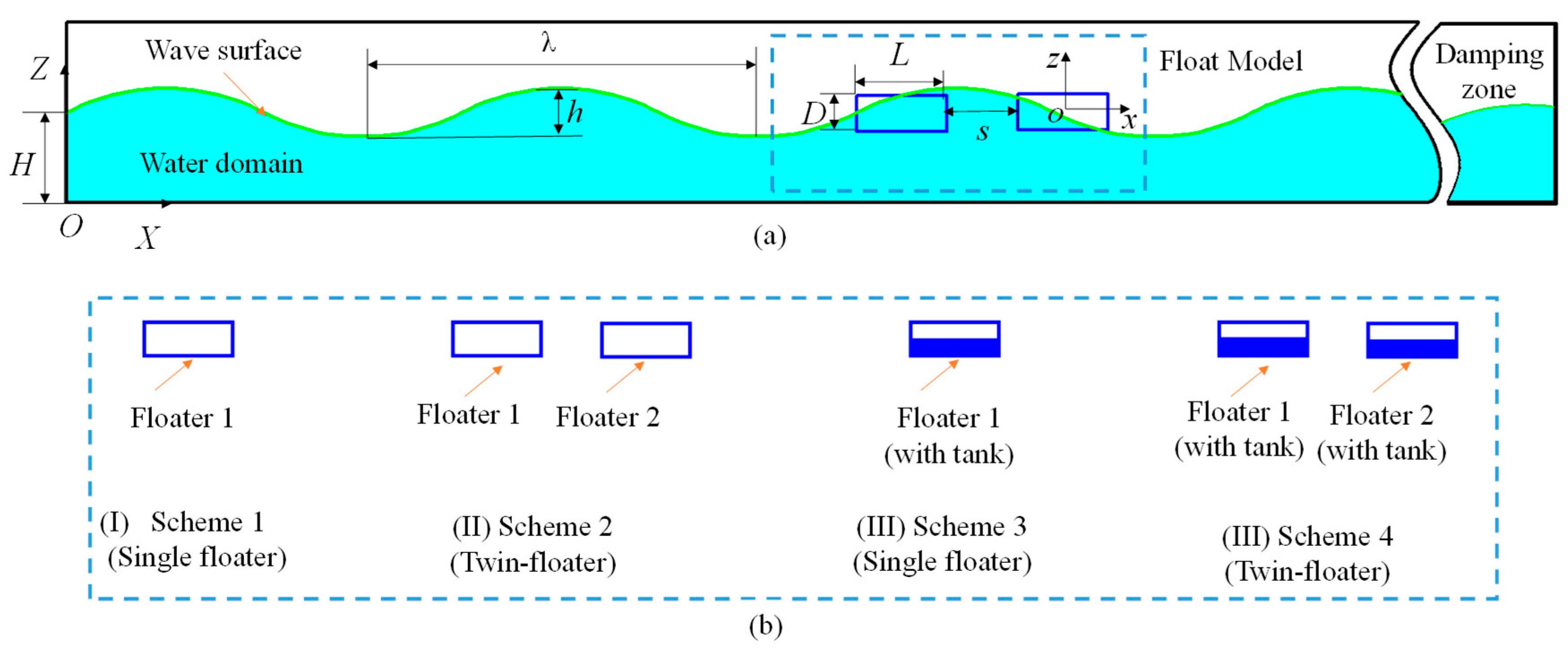
Figure 7: Sketch of the numerical wave tank: (a) overview of the numerical tank and (b) floating body models.
The distance between the center of gravity of Floater 1 and the wave-maker is X = 5 m. For the cases of the twin-floater model, the gap distance between the two floating bodies is s = 0.2 m. For the cases of the single floater model, its location coincides with the Float 1, which is the front side one of the twin-floater. Only two degrees of freedom of heave and pitch are released for all the floating bodies. Two axial forces of the horizontal and vertical directions are monitored. Fig. 8 shows an illustration of the two degrees of freedom and force directions that are defined in the local coordinate system G-xz. The horizontal force represents the fluid force or fixing force acting on the body, while the vertical force represents the total force of fluid and gravity on the body.
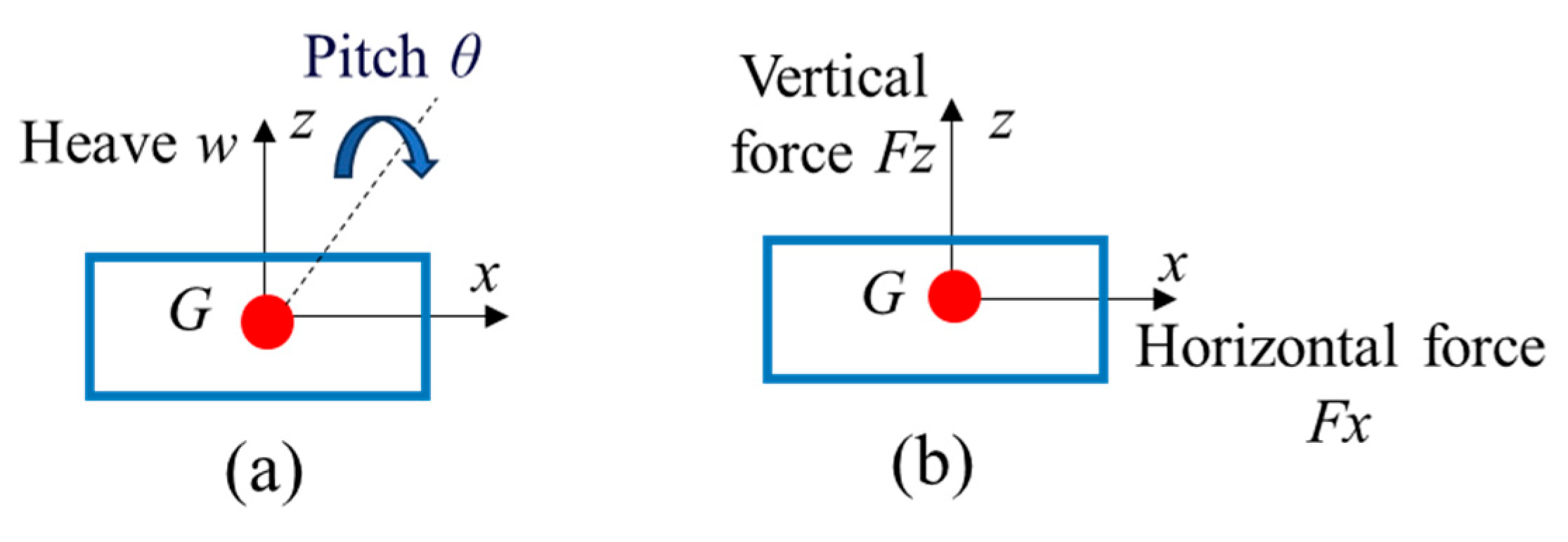
Figure 8: Definition of the movement and force of the floating body. (a) motion; (b) force.
To better extend the generality of the conclusions, the force is dimensionlessized by:
In this study, regular waves with constant wave height of h = 0.1 m are used, while the response of the floating body under different cases are involved by changing the wave length or wave number k. Table 1 lists the detailed calculation conditions. Table 2 explains the corresponding wavelengths and wave periods of each wave number.
For all the calculations, an AMD3990X 64-core CPU processor and an RTX3090 24 GB GPU were used. The number of particles is set to 488,785. The simulation time step size is 0.05 s. The calculation time consumed for each condition is approximately 1.5 h.
Table 1: Work conditions used in this study.
| Case ID | Floater Type | Wave Number k |
|---|---|---|
| Cases 1–11 | Scheme 1 | 1.4, 1.5, 1.55, 1.6, 1.7, 1.8, 1.9, 1.95, 2, 2.1, 2.2 |
| Cases 12–22 | Scheme 2 | 1.4, 1.5, 1.55, 1.6, 1.7, 1.8, 1.9, 1.95, 2, 2.1, 2.2 |
| Cases 23–33 | Scheme 3 | 1.4, 1.5, 1.55, 1.6, 1.7, 1.8, 1.9, 1.95, 2, 2.1, 2.2 |
| Cases 34–44 | Scheme 4 | 1.4, 1.5, 1.55, 1.6, 1.7, 1.8, 1.9, 1.95, 2, 2.1, 2.2 |
Table 2: Wavelengths and periods corresponding to different wavenumbers under regular waves.
| Wavenumber k | 1.4 | 1.5 | 1.55 | 1.6 | 1.7 | 1.8 | 1.9 | 1.95 | 2 | 2.1 | 2.2 |
| Wavelength λ (m) | 2.23 | 2.07 | 2 | 1.94 | 1.83 | 1.73 | 1.65 | 1.59 | 1.57 | 1.49 | 1.41 |
| Period T (s) | 1.27 | 1.21 | 1.18 | 1.16 | 1.12 | 1.08 | 1.05 | 1.03 | 1.02 | 0.99 | 0.96 |
3.3 Verification and Convergence Analysis
Both the time step size and the particle spacing affect the convergence of the results. For the particle spacing dp, three sets of spacings are selected: dp = 0.01 m, 0.004 m and 0.002 m. Fig. 9 compares the time series of motions of Floater 1 of the twin-floater system (Scheme 3) that obtained by the three particle spacing schemes for Case 16 with wave number k = 1.7 and wave height h = 0.1 m. The motion state of the floating bodies and flow distribution by the three different particle spacings at a same time instant are compared in Fig. 10. This reveals that the result by the medium particle spacing dp = 0.004 m agree well with the fine particle spacing dp = 0.002 m. Therefore, the convergence analysis on the time step size is further conducted using the medium particle spacing dp = 0.004 m.
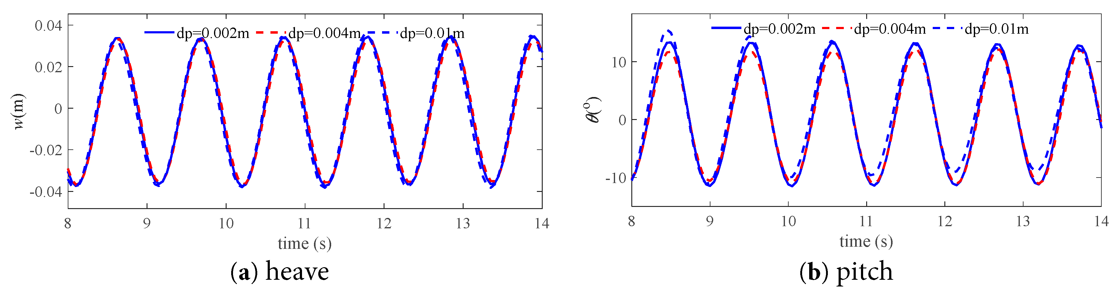
Figure 9: Convergence verification of particle spacing (Case 16).
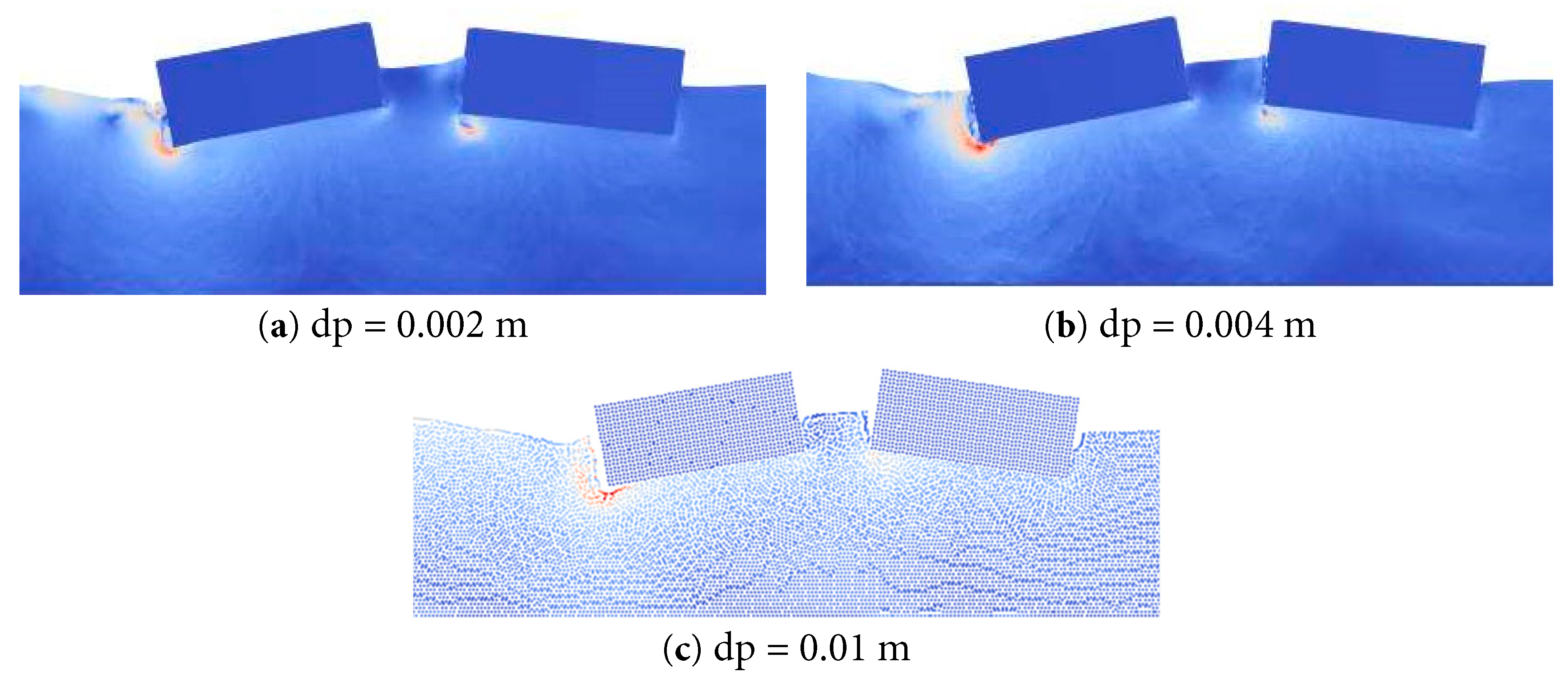
Figure 10: Motion state of the floating bodies and flow distribution by different particle spacings (Case 16).
The motion response results by three sets of time step, i.e., 0.05 s, 0.01 s, and 0.005 s, are compared in Fig. 11. The results indicate that the calculated motions are highly consistent between the three different time step sizes. As a compromise of the calculation efficiency and accuracy, the parameters of particle spacing dp = 0.004 m and time step size dt = 0.05 s are chosen for the subsequent numerical calculations.
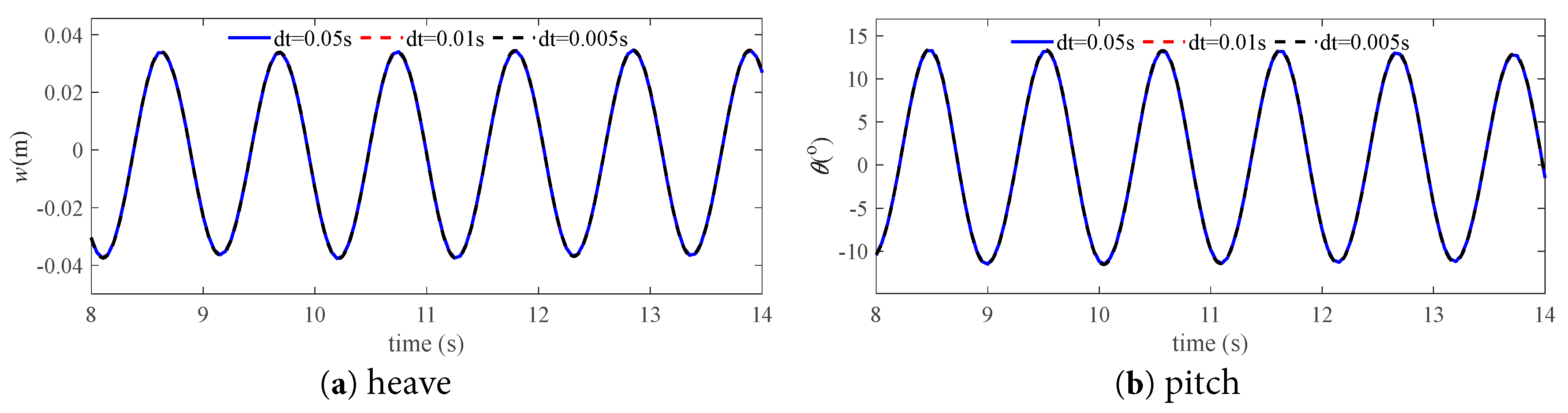
Figure 11: Time step convergence verification (Case 16).
4 Analysis and Comparison of the Results
In this section, the hydrodynamic behaviours of single- and twin-floating bodies are comparatively analyzed, which mainly concentrate on the heave and pitch motions as well as the horizontal and vertical forces on the floating bodies. The analyses are conducted for the cases of floaters without and with liquid tank.
4.1 Comparison between One- and Twin-Floater without Liquid Tank
In this part, the flow characteristics and dynamic behavior of the free-floating bodies under wave excitation are investigated. The response is compared between the one- and twin-floater systems.
The variation in the motion amplitude of the floating bodies without liquid tank under different incident wave cases is shown in Fig. 12, where the results of the three floaters are presented for comparison. In general, for all three floaters the largest motion response amplitude is at k = 1.55 (corresponding to period T = 1.18 s) where the resonance responses of the floating body system occur. The resonance period is close to the natural period of the water in the narrow gap Tg = 1.11 s which is obtained according to the study of Jing et al. [21]. The motion response of Floater 2 in the twin-floater system is the lowest among the three floaters over the whole wave number range. This is caused by the incident wave shielding effects due to the presence of the Floater 1, which is located in front of the Floater 2 [40]. The difference in the heave motion of Floater 1 between the one- and twin-floater systems is small. However, the pitch motion of Floater 1 in the twin-floater system is much greater than that of the single one, especially at the resonance wave range. As the wave number increases, the pitch amplitudes of Float 1 are close for the one- and twin-floater systems.
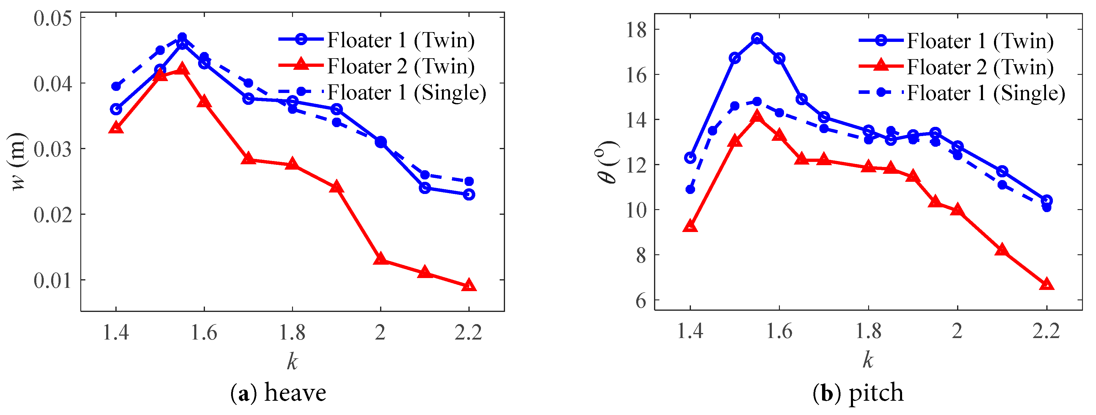
Figure 12: Motion amplitudes of the floating bodies without tank at different wave numbers.
Fig. 13 and Fig. 14 compare the time series of motion between the three floaters for the two cases with the wave number k = 1.55 and k = 2.2, respectively. It is seen that there is an obvious phase lag in the motion signal between the Floater 1 and Floater 2 in the twin-floater system, while the phase is almost the same for the Floater 1 of the one- and twin-floater systems. This shows that in a twin-floater system, the gap flow has an important effect on the floating body at the rear (Floater 2), but has little effect on the floating body at the front (Floater 1). The motion amplitude value of Floater 2 is much lower than that of Floater 1 in the case of k = 2.2, which is also reflected in the amplitude variation results. This shows that both the amplitude and phase of the rear floating body (Floater 2) in the twin-floater system are affected by the gap flow.
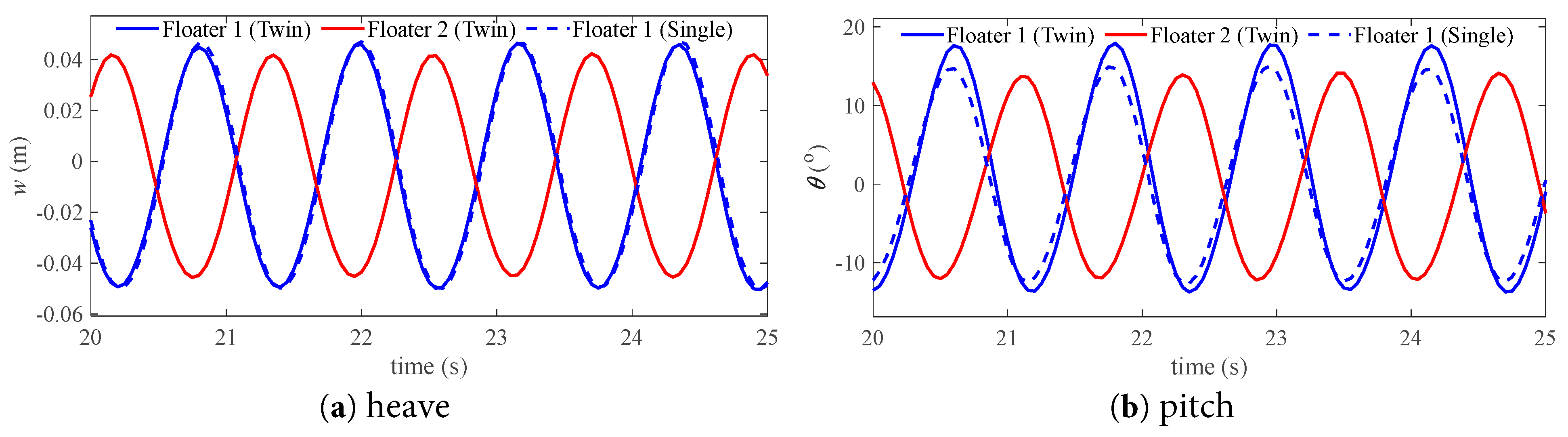
Figure 13: Comparison of the motion time series of the floating bodies without tank in the case of k = 1.55.
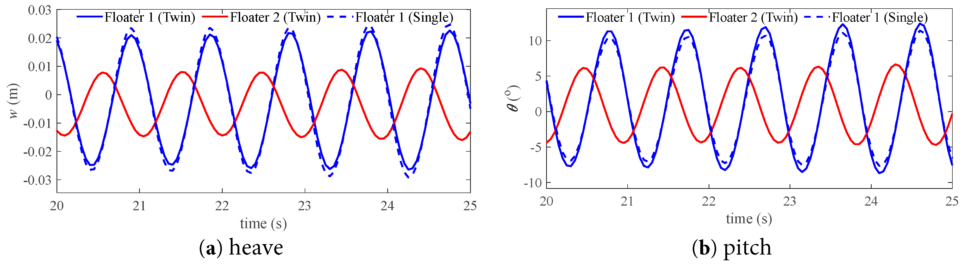
Figure 14: Comparison of the motion time series of the floating bodies without tank in the case of k = 2.2.
To provide a deeper understanding of the resonance mechanism, Fig. 15 presents the distribution of the flow field velocity around the floating bodies at the resonance response case of k = 1.55. It is seen that the magnitude of flow speed around Floater 1 is greater than that of Floater 2 in the twin-floater system. The presence of Floater 2 introduces additional fluid disturbances and interference effects in the flow field. These effects superimpose on the flow field originally generated by Floater 1. This results in an increase in the velocity amplitude around Floater 1 in the twin-floater system compared to the case of a single float.
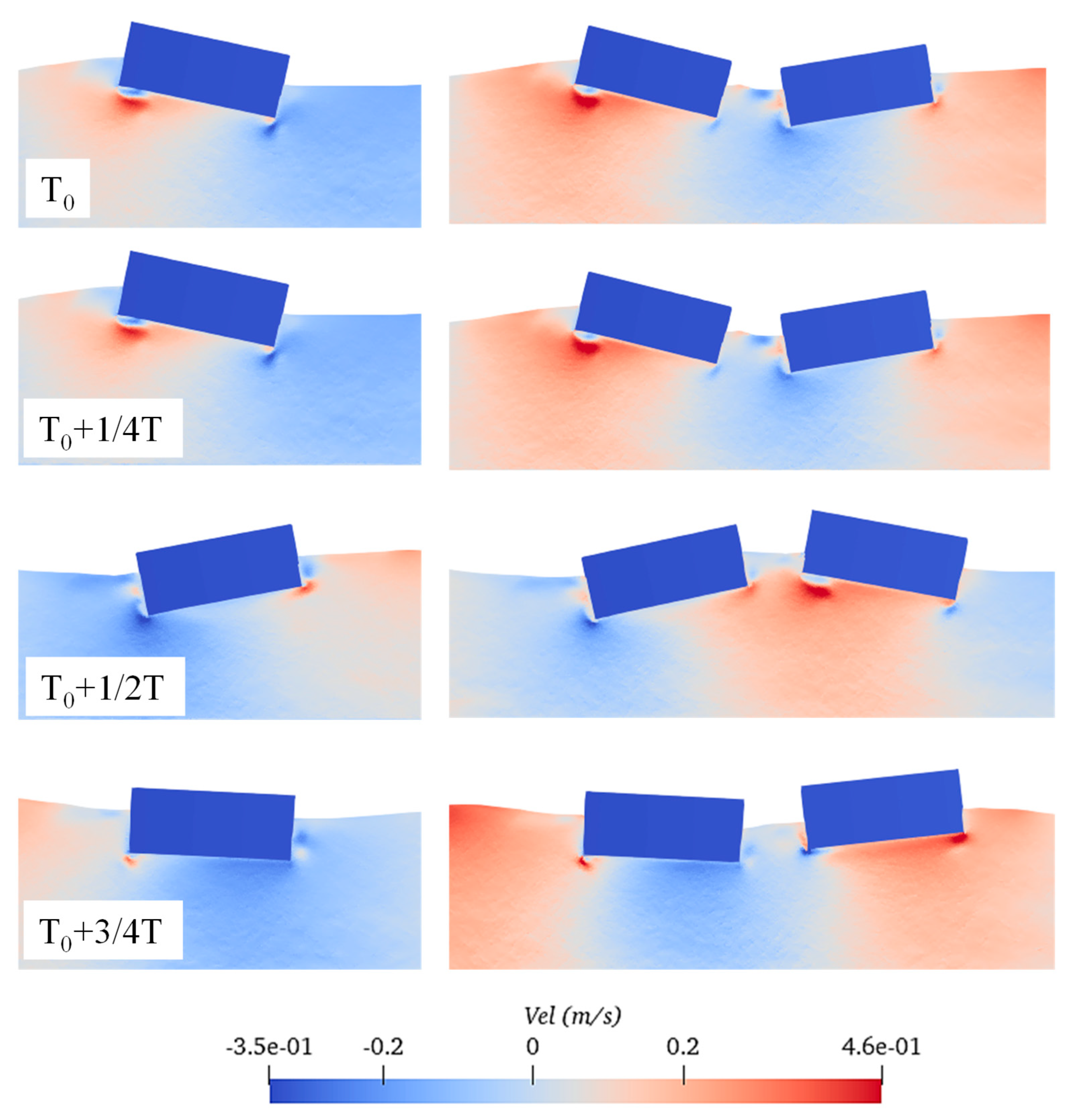
Figure 15: Distribution of the flow velocity field around the floating bodies under resonance condition of k = 1.55.
Fig. 16 shows the variation in the horizontal and vertical force amplitude on the floating bodies without liquid tank under different incident wave cases. It can be observed that the horizontal force on the floating body reaches the peak value at the resonant frequency of wave number k = 1.55. Moreover, a second resonance peak appears at k = 1.9, although this peak is lower than the first peak at k = 1.55. When it comes to the vertical force, the largest peak occurs at k = 1.9, which is much greater than the peak at k = 1.55. The force amplitude of Floater 2 is much lower than that of Floater 1 due to the wave shielding effect.
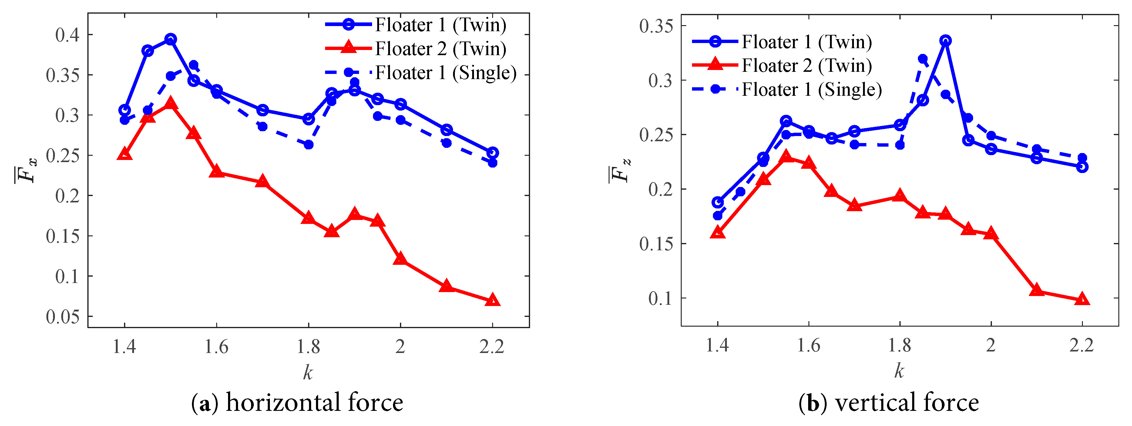
Figure 16: Force amplitudes of the floating bodies without tank at different wave numbers.
Fig. 17 and Fig. 18 compare the time series of force between the three floaters for the two cases with the wave number k = 1.55 and k = 2.2, respectively. It can be seen that the force signal is not as smooth as the motion signal and the force signal contains high-frequency vibrations. There is a phase difference between the two floaters in the twin-floater system.
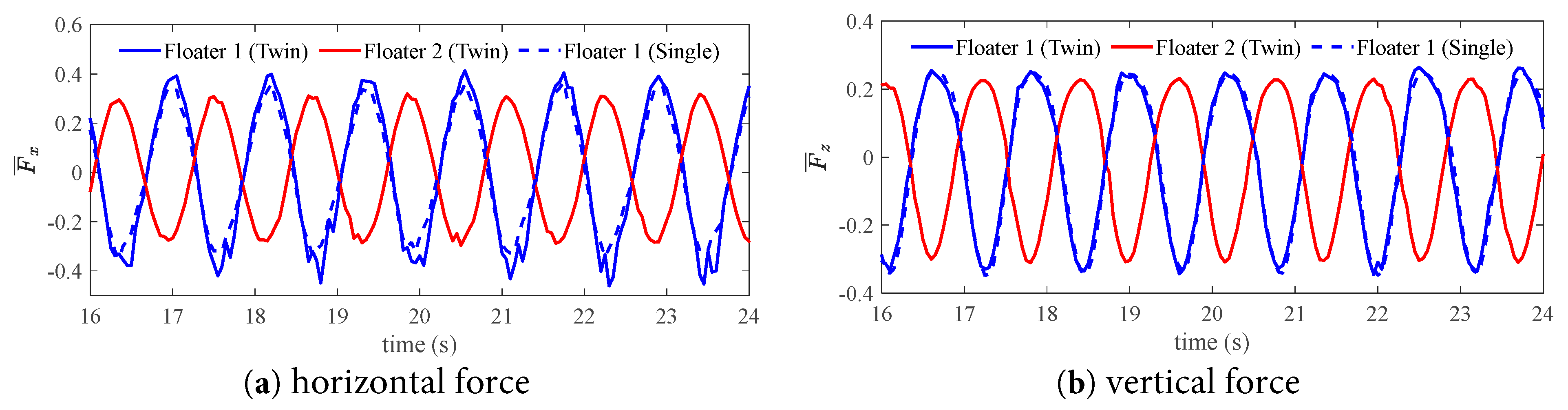
Figure 17: Comparison of the force time series of the floating bodies without tank in the case of k = 1.55.
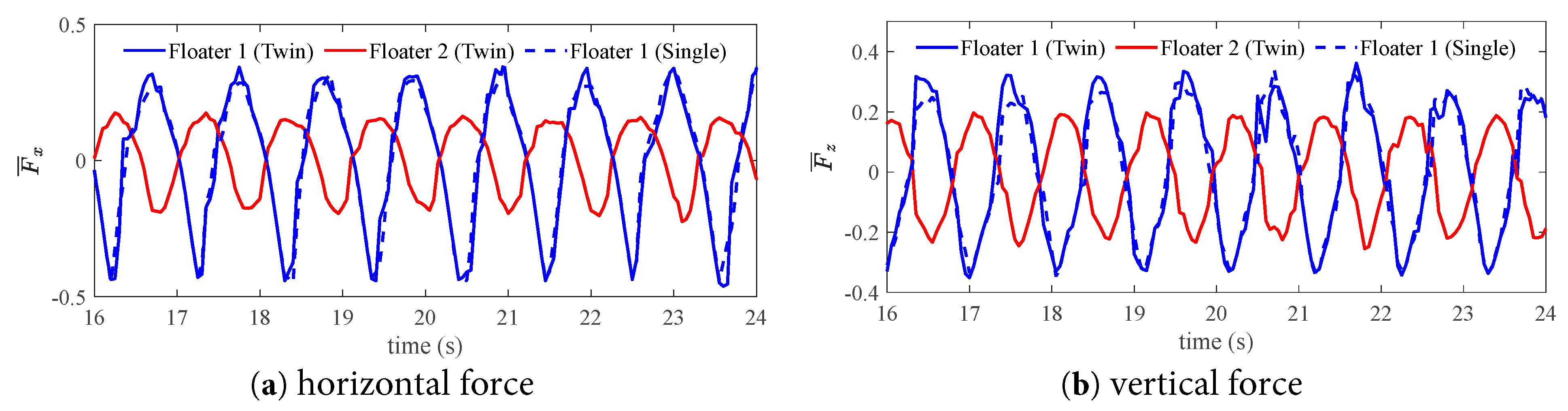
Figure 18: Comparison of the force time series of the floating bodies without tank in the case of k = 1.9.
It can be seen that, compared to the motion signal presented in Fig. 13, the force signal appears less smooth, indicating the presence of high-frequency vibration components in the force signal. When subjected to wave impacts, the pressure distribution on the surface of the floating body is nonlinear. Moreover, there is a sequential order in the occurrence of impact loads along the direction of wave propagation (see Fig. 19). Since force is obtained by integrating pressure over the surface area of the floating body, the force signal exhibits some high-frequency characteristics. Upon further comparison with Floater 1, it is evident that the high-frequency components in the twin-floater system are significantly more numerous than those in the single floater system. Fig. 20 shows the frequency components of the dimensionless force obtained by applying FFT on the time series. Within the primary frequency range of 0–6 Hz, multiple high-frequency fluctuations are present in the horizontal force, whereas only two major high-frequency fluctuations exist in the vertical force. This characteristic makes the high-frequency components of the horizontal force more prominent compared to those of the vertical force. For the high-frequency components of the horizontal force, the energies at 1.1 Hz, 2.1 Hz, and 4 Hz for Floater 1 in the twin-floater system are significantly higher than those in the single floater system. This low frequency 1.1 Hz can be regarded as the main excitation frequency caused by the wave, which is related to the frequency of the wave itself. While the frequency 2.1 Hz is nearly twice the main frequency, it is the frequency-doubling effect of the wave. And the larger 4 Hz causes higher vertical vibration, which may be related to the vertical vibration frequency of the floating body itself. These high-frequency components are the fundamental reason why the time history response of Floater 1 in the twin-floater system is higher than that in the single floater system.
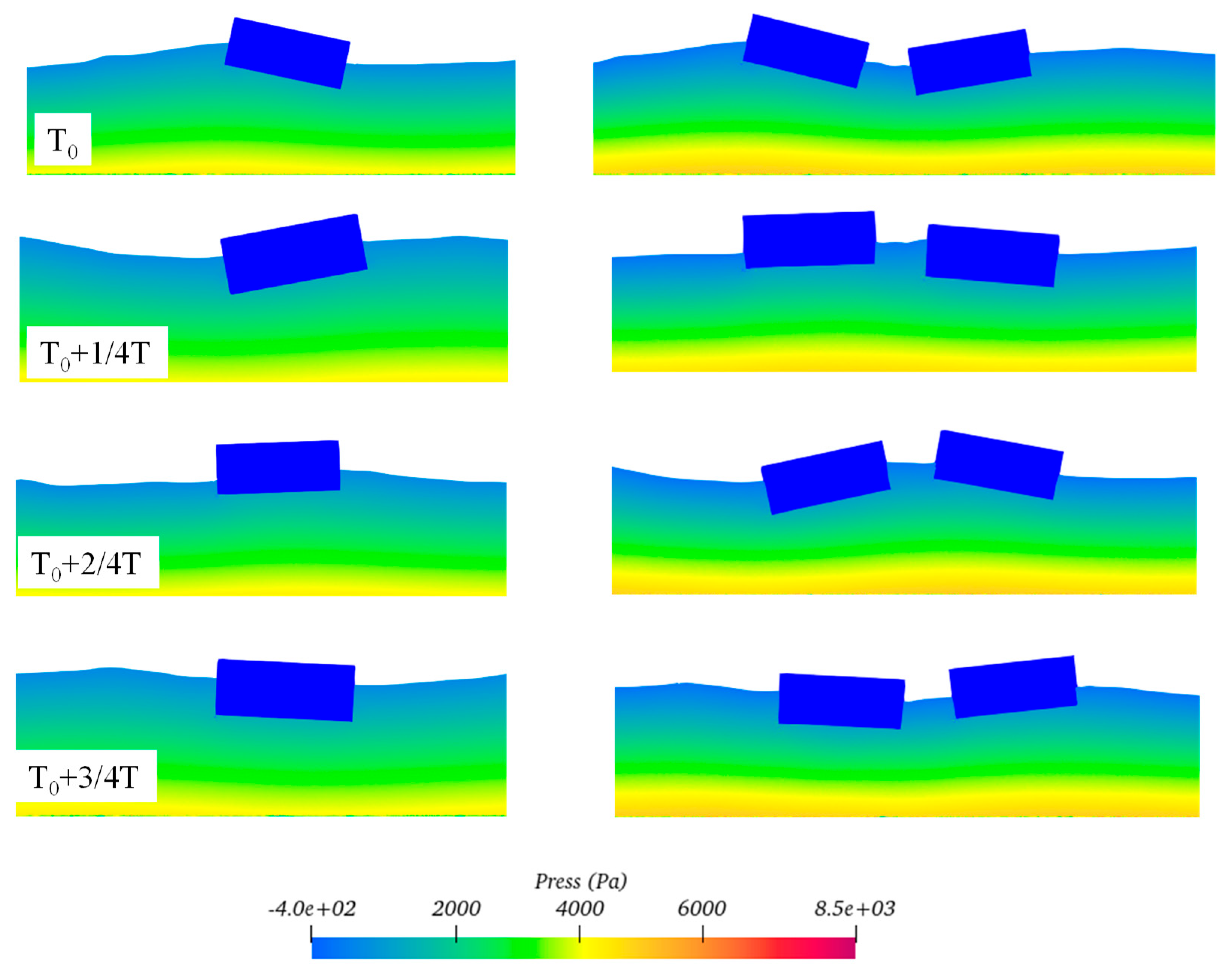
Figure 19: Distribution of the pressure field around the floating bodies under resonance condition of k = 1.55.
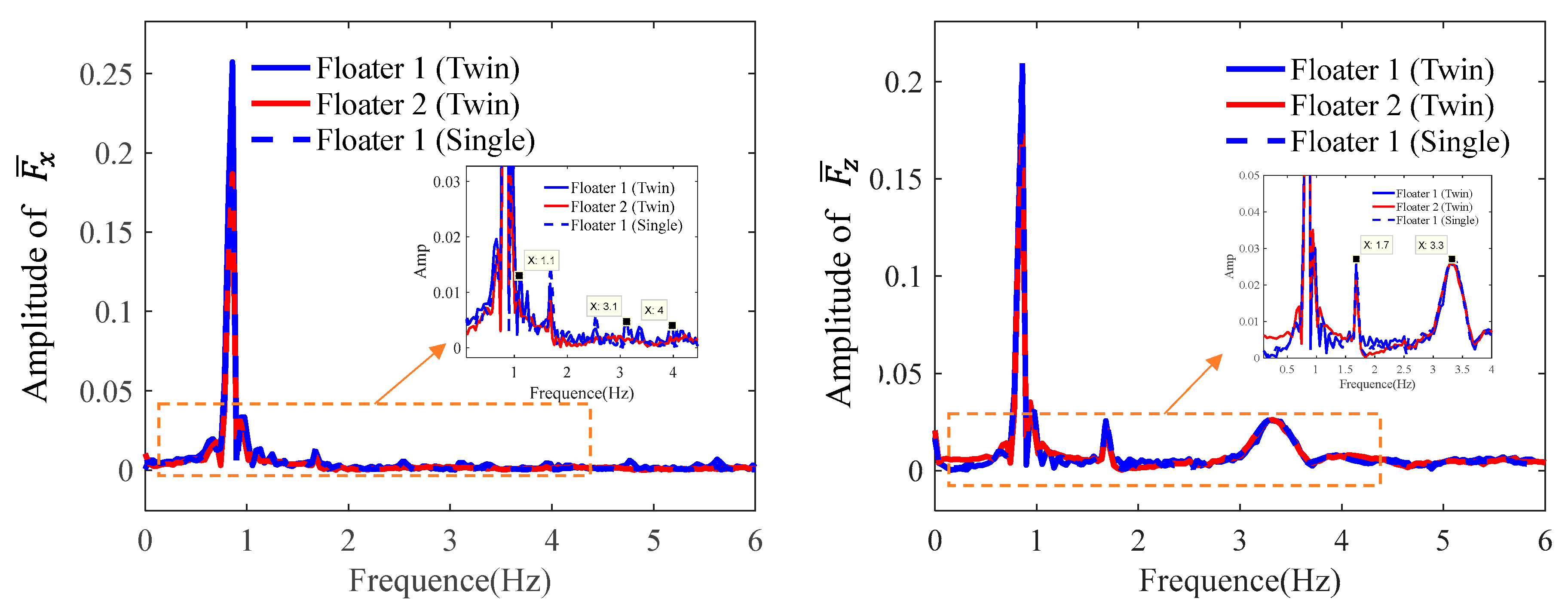
Figure 20: Comparison of the frequency component of the floating bodies without tank in the case of k = 1.55. (a) Horizontal force; (b) Vertical force.
4.2 Comparison between One- and Twin-Floater with Liquid Tank
In this part, the flow characteristics and dynamic behavior of the free-floating bodies with internal liquid tank under wave excitation are investigated. The response is compared between the one- and twin-floater systems.
The variation in the motion amplitude of the floating bodies with liquid tank under different incident wave cases is shown in Fig. 21. The heave amplitude generally exhibits a decrease trend as the wave number increases from k = 1.4 to 2.2. Compared to conventional floating bodies without liquid tanks, those with liquid tanks do not exhibit prominent resonance phenomena. This indicates that the presence of liquid inside the structure can effectively prevent the occurrence of resonance. For the twin-floater system, the motion amplitude of Floater 2 is much lower than that of Floater 1. This trend is consistent with the behavior of twin-floater system without liquid tanks, primarily due to the shielding effect of the overhead structure. In the range of lower wave numbers, the heave amplitude of Floater 1 in the single floater system is lower than that in the twin floater system; however, in the range of higher wave numbers, the heave amplitude of Floater 1 in the single floater system exceeds that in the twin floater system. Nevertheless, in terms of pitch amplitude, Floater 1 in the single and twin systems exhibits opposite patterns. This suggests that the sloshing of the internal liquid tank enhances the heave amplitude response at low frequencies but reduces the pitch response; whereas at high frequencies, the situation is reversed.
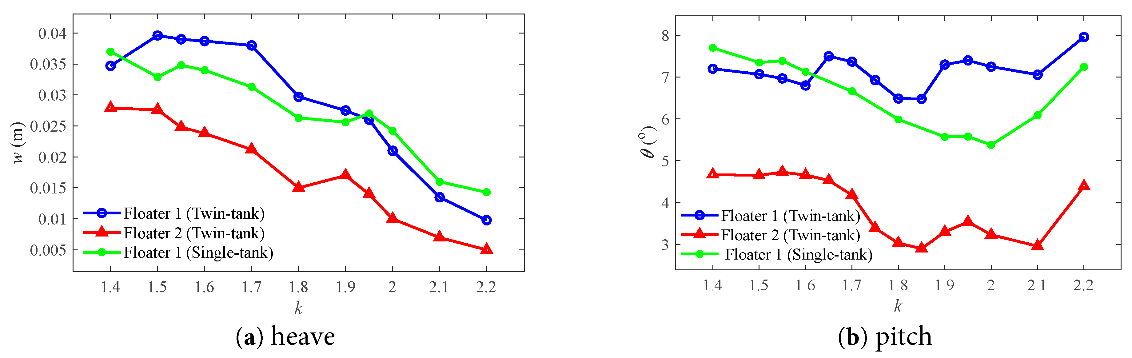
Figure 21: Motion amplitudes of the floating bodies with tank at different wave numbers.
Fig. 22 presents the time series of the three floating bodies’ motion in the case of wave number k = 1.7. It is seen that the heave signal shows standard sine in shape, but the pitch signal shows obvious nonlinearity due to internal tank sloshing. The difference in pitch of Floater 1 between single and twin systems is obvious, especially at the troughs. The pitch value of Floater 1 is generally greater than that of Floater 2 due to the obvious trim state of Floater 1 in waves. The motion amplitude of Floater 2 is lower due to the sheltering effect [41].
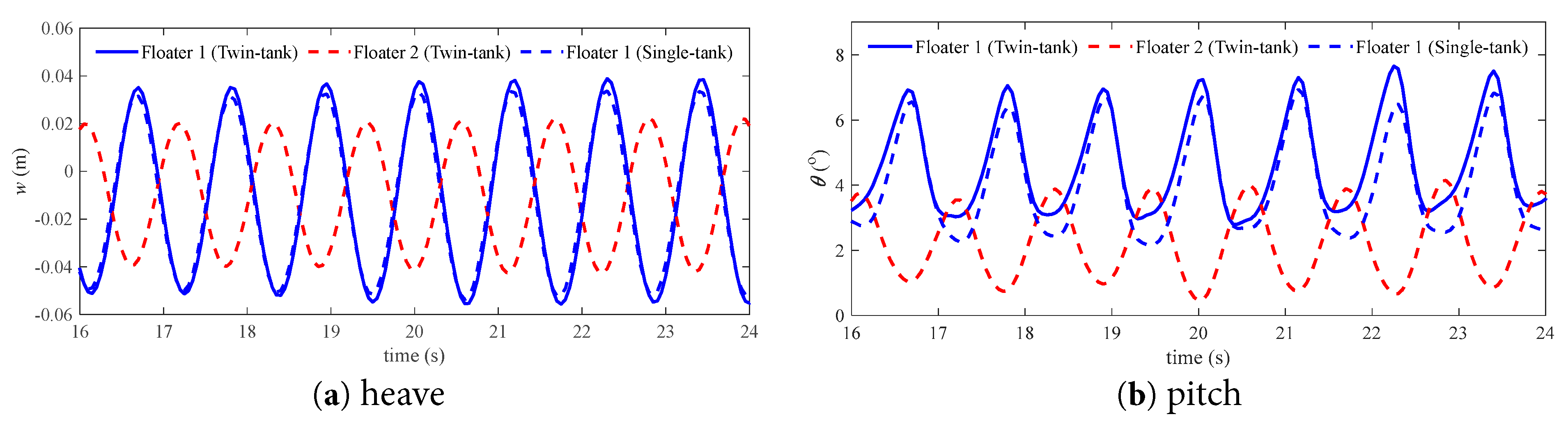
Figure 22: Comparison of the motion time series of the floating bodies with tank in the case of k = 1.7.
Fig. 23 presents the flow pattern and velocity distribution inside and outside the floating bodies in an resonant state of k = 2.2. It is found that the wave pattern and speed distribution around Floater 1 is the almost the same for the single and twin systems. The flow speed around Floater 2 is much lower than that of Floater 1. And the internal tank sloshing effect in Floater 2 is not significant.
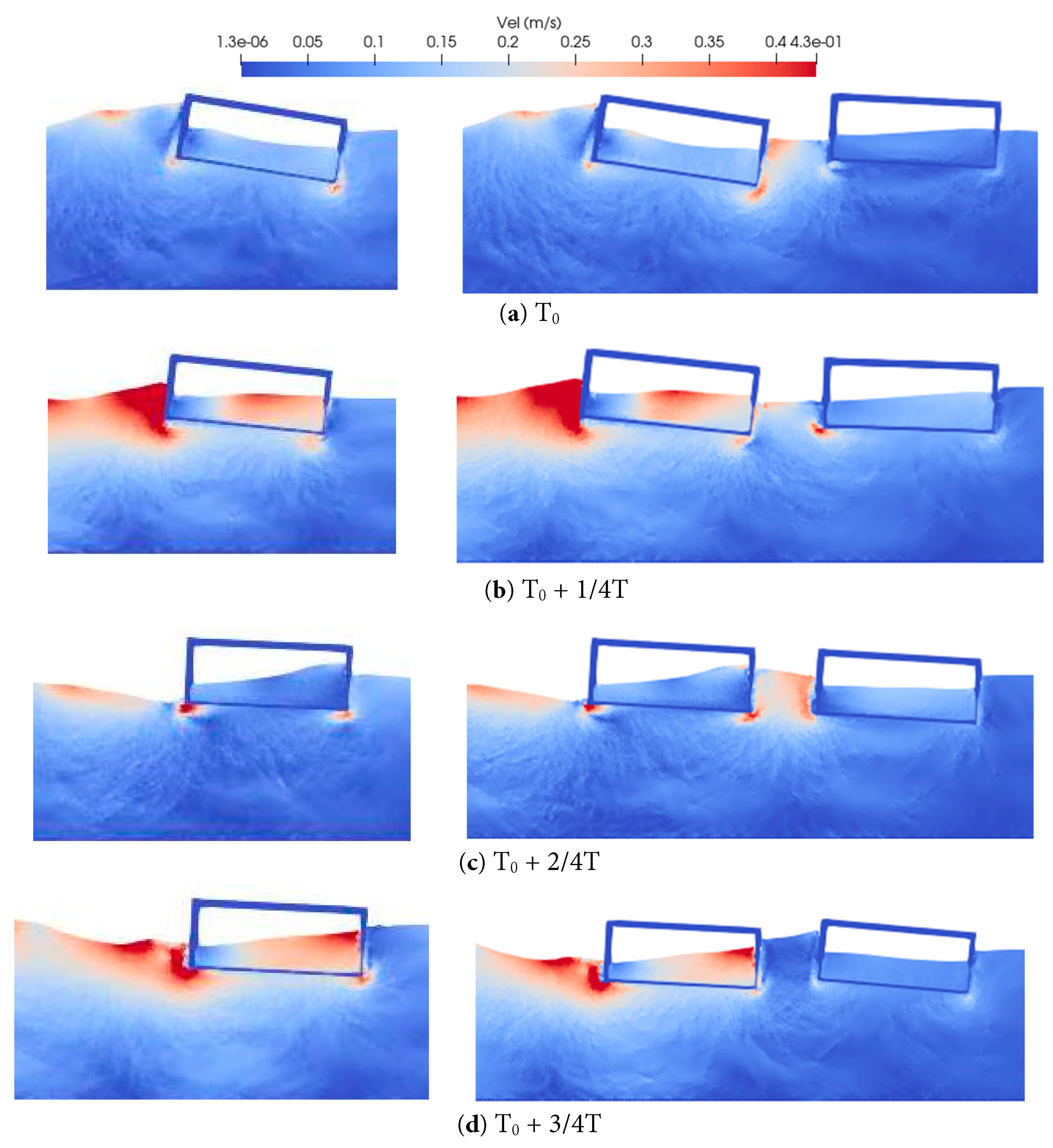
Figure 23: Distribution of the flow velocity field around the floating bodies with tank under condition of k = 2.2.
Fig. 24 shows the variation in the horizontal and vertical force amplitude on the floating bodies with liquid tank under different incident wave cases. Two peaks are identified in the horizontal force curves, which are around k = 1.7 and 1.9. However, only one peak around k = 1.7 can be identified in the vertical force curve, which is different from the results without tank.
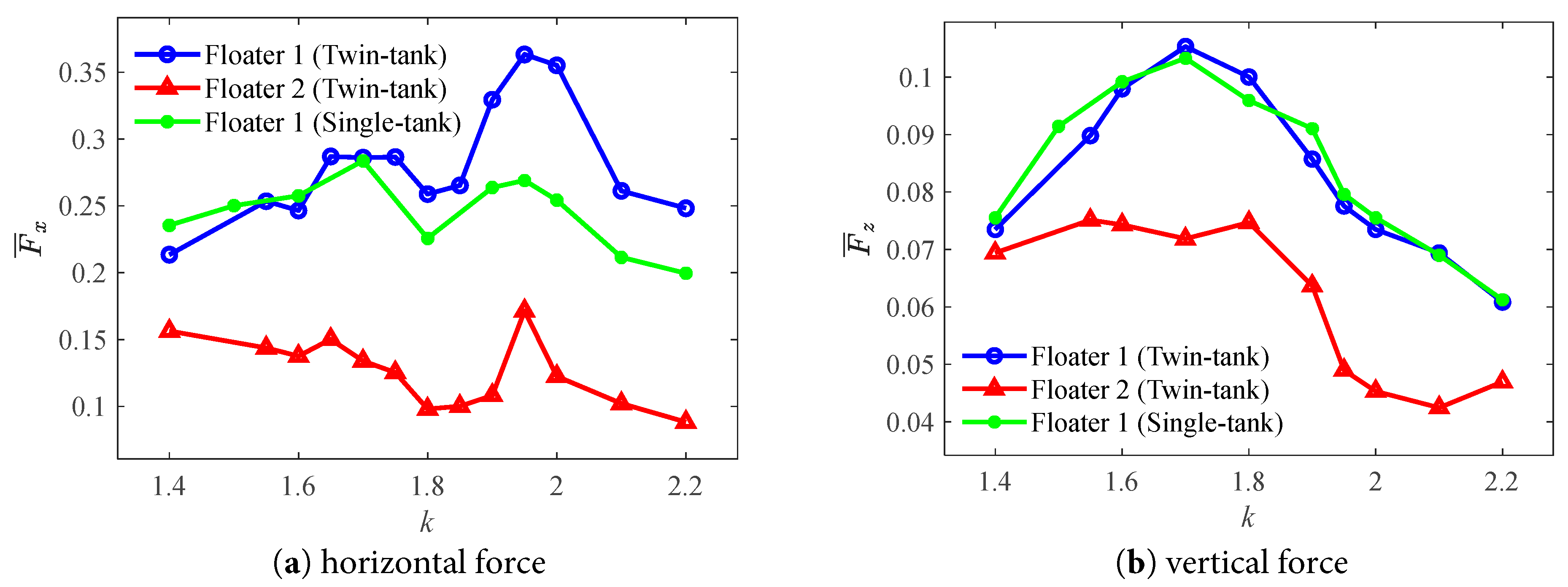
Figure 24: Force amplitudes of the floating bodies with tank at different wave numbers.
Fig. 25 illustrates the time history of the dynamic response experienced by the floating bodies with tank under the wave number k = 1.95. Significant differences in phase and amplitude among the three floating bodies can be observed. Further analysis, based on the pressure distribution presented in Fig. 26, reveals that the overall pressure levels of the three floating bodies are similar. However, the free surface shapes within their internal liquid tanks vary. This inconsistency in free surface shapes is a crucial factor contributing to the differences in forces acting on the floating bodies, with the relative positions and morphological changes of the internal and external submerged surfaces playing a decisive role.
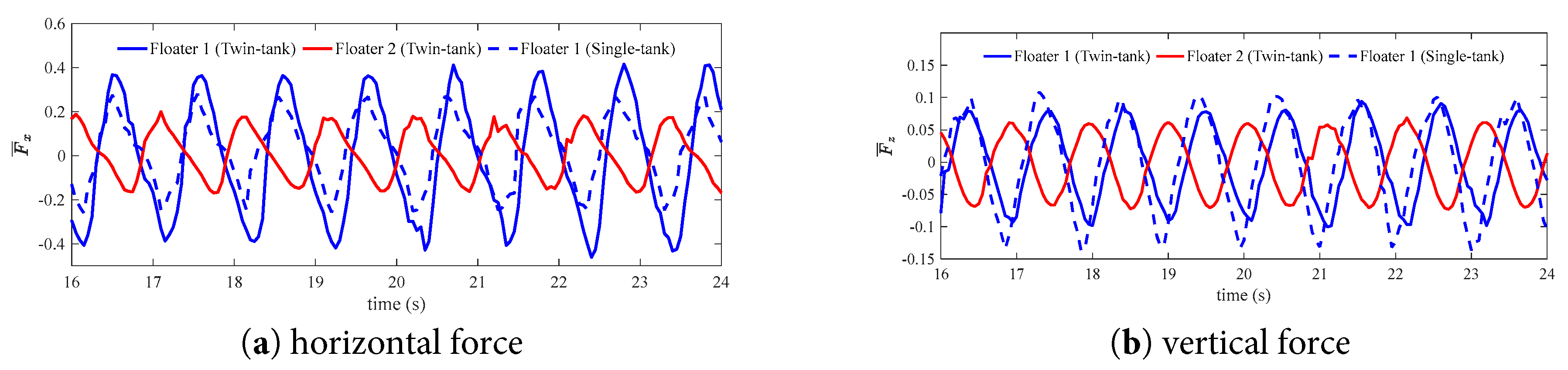
Figure 25: Comparison of the force time series of the floating bodies with tank in the case of k = 1.95.
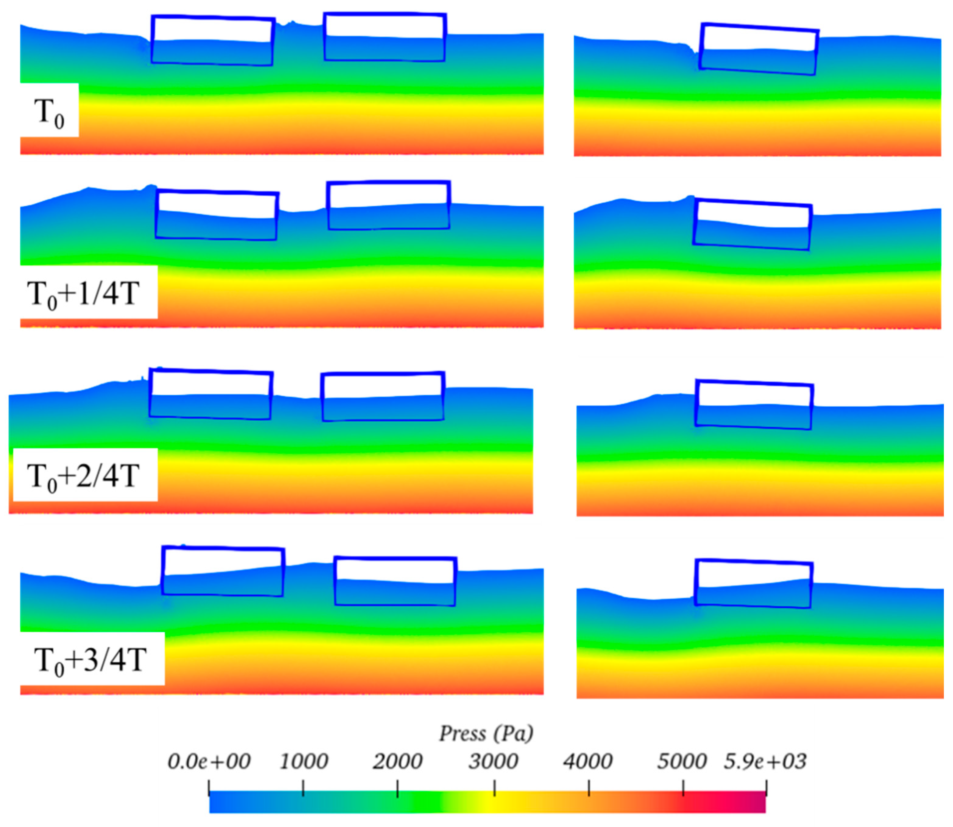
Figure 26: Distribution of the pressure field around the floating bodies under resonance condition of k = 1.95.
To gain a deeper understanding of the frequency components of these dynamic characteristics, Fig. 27 provides an analysis of the frequency features within the time history signals. Within the frequency range of 0 to 6 Hz, the horizontal force components exhibit two distinct high-frequency fluctuation characteristics, while the vertical force components show two significant high-frequency fluctuations only in the case of a single floater with tank. This result indicates that high-frequency components are more prominent in the horizontal force components compared to the vertical force components. For the high-frequency components of the horizontal force, in the twin-floater system, the energy contributed by Floater 1 is significantly higher than that in the single-floater system. This suggests that the fluid dynamic interference between floats in the twin-floater system enhances the energy transfer and accumulation effects at specific frequencies.
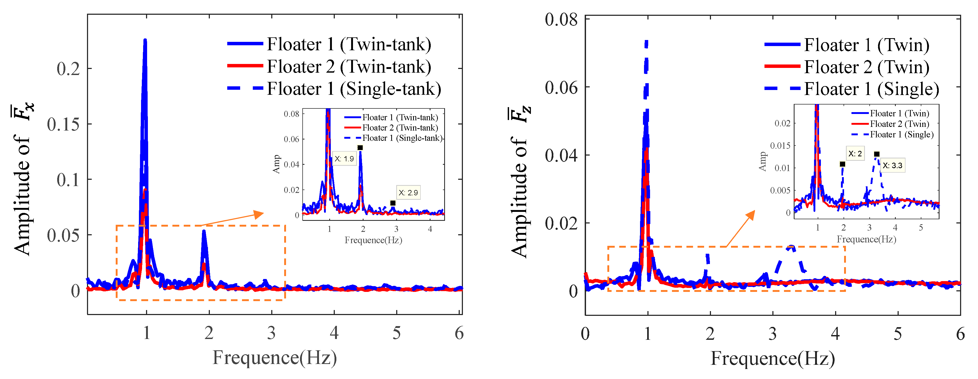
Figure 27: Comparison of the frequency component of the floating bodies with tank in the case of k = 1.95. (a) horizontal force; (b) vertical force.
4.3 Effects of the Liquid Tank on the Hydrodynamic Characteristics
Fig. 28 compares the motion time series between the twin floaters with and without internal tank for the case of k = 1.95. It is seen that the heave motion for the floaters with and without internal tank is close although the floater with tank has a lower mean value. However, the pitch of the floater with the tank is much lower than the one without tank. This indicates that the internal tank has the obvious effect on reducing the pitch motion of the floating body, which acts as an anti-rolling tank. A comprehensive comparison of the movement of the floating bodies and fluid field within one wave period between the four schemes is shown in Fig. 29.
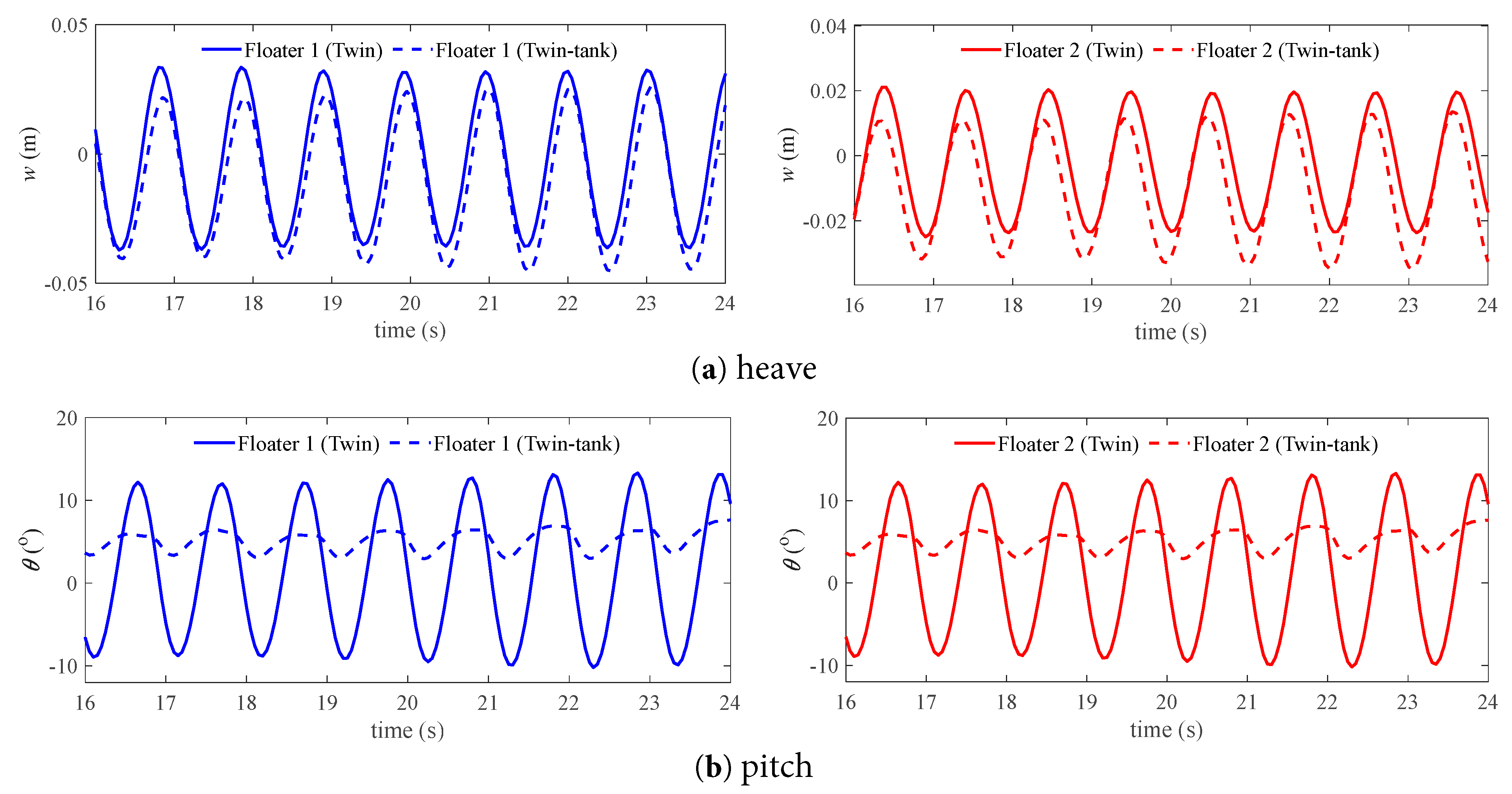
Figure 28: Comparison of the motion time series of the floating bodies with and without tank in the case of k = 1.95.
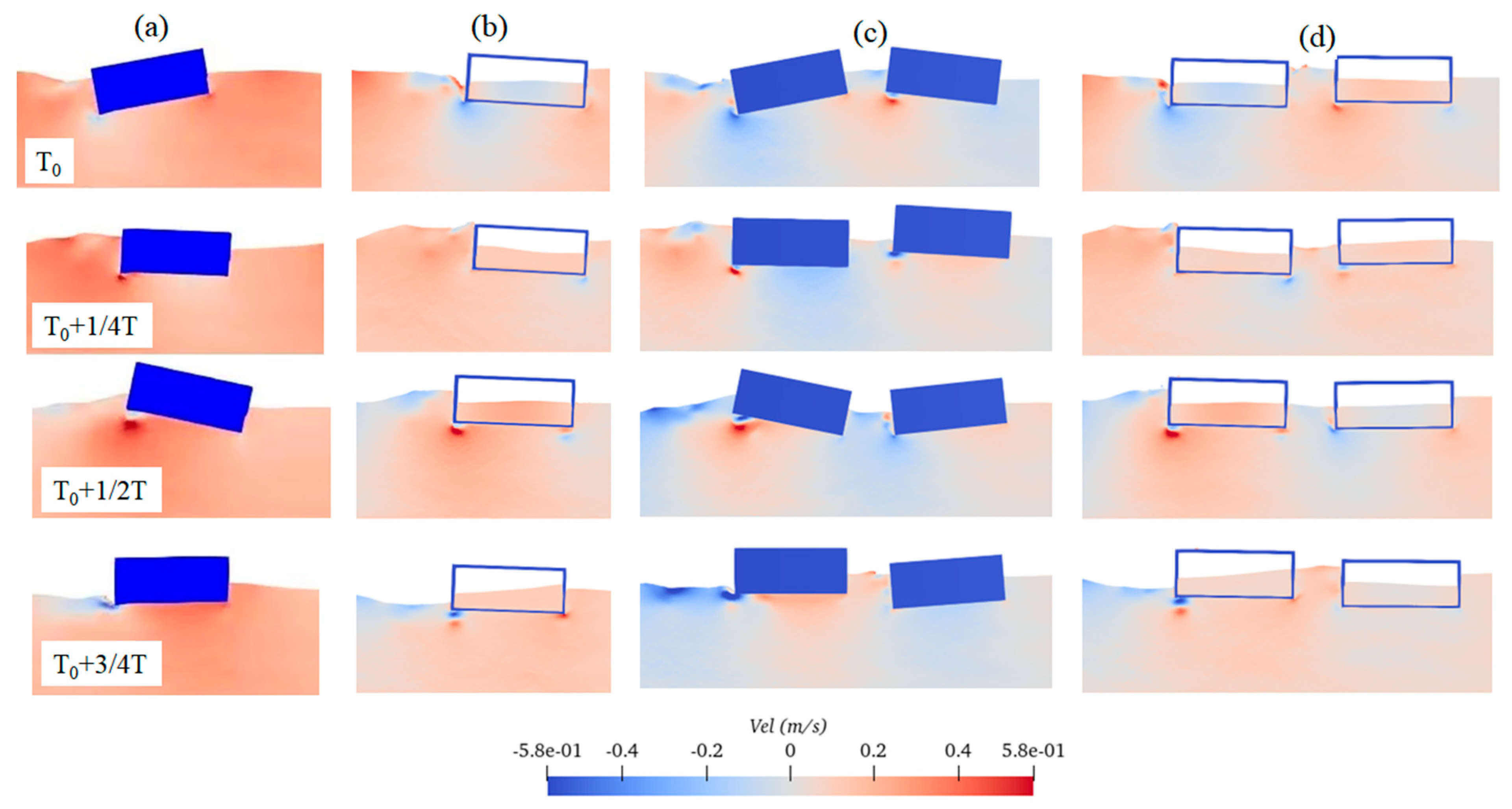
Figure 29: Figure 29: Comparison of movement of the floating bodies and fluid field within one wave period for the case of k = 1.95: (a) Scheme 1, (b) Scheme 2, (c) Scheme 3, and (d) Scheme 4.
Fig. 30 compares the force time series between the twin floaters with and without internal tank for the case of k = 1.95. It is seen that the horizontal force for the floaters with and without internal tank is close. However, the vertical force of the floater with the tank is much lower than the one without the tank. This is due to the fact that the fluid force on the floaters with internal tank contains the resultant forces of both internal and external forces.
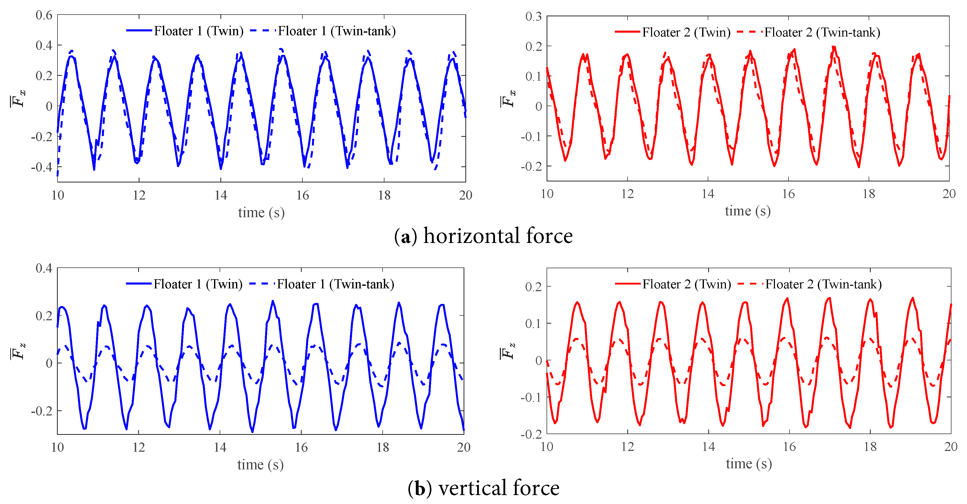
Figure 30: Comparison of the force time series of the floating bodies with and without tank in the case of k = 1.95.
This paper conducts numerical simulations on the hydrodynamic behaviour of a 2D twin-floater system with and without the liquid tank using the open-source code DualSPHysics. The following conclusions can be obtained:
- (1)The present SPH method well simulates the resonance response of the gap flow between two bodies. The wave elevation height in the narrow gap between two fixed bodies can be five times larger than the incident waves.
- (2)The motion response of the downstream Floater 2 in the twin-floater system is lower than that of the upstream, which is caused by the incident wave shielding effects. Two response peaks can be identified from the amplitude value curves at different wave numbers.
- (3)The internal tank can largely reduce the pitch motion of the floating body while it has little effect on the heave motion. The internal tank can largely reduce the vertical force on the floating body while it has little effect on the horizontal force.
The study in the work is limited to the 2D plane problem of both the fluid field and the floating body; the effect of 3D on the results can be studied in future work. A systematic study on the gap distance on the hydrodynamic behaviour of both multi-floating bodies’ motions and internal sloshing can be further explored. The developed method can be applied to the simulation of real application scenarios, such as the Floating Liquefied Natural Gas (FLNG) system offloading with an LNG ship in a side-by-side arrangement system.
Acknowledgement:
Funding Statement: This work was supported by the National Natural Science Foundation of China (Nos. 52271316 and 12302314) and the Science and Technology Project in Guangzhou (No. 2024A04J9886).
Author Contributions: The authors confirm contribution to the paper as follows: Conceptualization, Jialong Jiao and Hang Xie; methodology, Yuanming Chen and Mengyun Jiang; software, Mengyun Jiang and Yuanming Cheng; writing, Mengyun Jiang; funding acquisition, Jialong Jiao. All authors reviewed the results and approved the final version of the manuscript.
Availability of Data and Materials: Data available on request from the authors.
Ethics Approval: Not applicable.
Conflicts of Interest: The authors declare no conflicts of interest to report regarding the present study.
Abbreviations
| Parameter Notation | Parameter Definition | Parameter Notation | Parameter Definition |
| S0 | Piston stroke | p | Pressure |
| | Dimensionless vertical force | Wave length | |
| Fz | Vertical force | t | Time |
| | Dimensionless horizontal force | Δt | Time step |
| Fx | Horizontal force | T | Wave period |
| D | Body’s depth | v | Fluid velocity |
| s | Narrow gap | c | Sound speeds of particles |
| δ | Initial phase | ρ | Fluid density |
| dp | Particle spacing | d | Water depth |
| l | Smoothing length | α | An adjustable coefficient |
| g | Gravity acceleration | Γ | Dissipation term |
| h | Wave height | m | Mass of adjacent particle |
| H | Initial water height | ω | Angular frequency |
| r | Displacement vector of the space point | k | Wave number |
| L | Body’s length | ||
| r′ | Displacement vector of the adjacent space point |
References
1. Zhao W, Milne IA, Efthymiou M, Wolgamot HA, Draper S, Taylor PH, et al. Current practice and research directions in hydrodynamics for FLNG-side-by-side offloading. Ocean Eng. 2018;158:99–110. doi:10.1016/j.oceaneng.2018.03.076. [Google Scholar] [CrossRef]
2. Lu L, Teng B, Sun L, Chen B. Modelling of multi-bodies in close proximity under water waves—fluid forces on floating bodies. Ocean Eng. 2011;38(13):1403–16. doi:10.1016/j.oceaneng.2011.06.008. [Google Scholar] [CrossRef]
3. Saitoh T, Miao GP, Ishida H. Theoretical analysis on appearance condition of fluid resonance in a narrow gap between two modules of very large floating structure. In: Proceedings of the Third Asia-Pacific Workshop on Marine Hydrodynamics; 2006 Jun 27–28; Shanghai, China. p. 170–5. [Google Scholar]
4. Fredriksen AG, Kristiansen T, Faltinsen OM. Experimental and numerical investigation of wave resonance in moonpools at low forward speed. Appl Ocean Res. 2014;47(9):28–46. doi:10.1016/j.apor.2014.03.005. [Google Scholar] [CrossRef]
5. Zhu RC, Miao GP, You YX. Influence of gaps between 3-D multiple floating structures on wave forces. J Hydrodyn Ser B. 2005;17(2):141–7. [Google Scholar]
6. Tan L, Tang GQ, Zhou ZB, Cheng L, Chen X, Lu L. Theoretical and numerical investigations of wave resonance between two floating bodies in close proximity. J Hydrod. 2017;29(5):805–16. doi:10.1016/S1001-6058(16)60792-8. [Google Scholar] [CrossRef]
7. Zhang Z, Liu W, Zheng X, Liu H, Li N. Numerical simulation of hydrodynamic oscillation of side-by-side double-floating-system with a narrow gap in waves. Open Phys. 2021;19(1):177–207. doi:10.1515/phys-2021-0021. [Google Scholar] [CrossRef]
8. Lu L, Cheng L, Teng B, Zhao M. Numerical investigation of fluid resonance in two narrow gaps of three identical rectangular structures. Appl Ocean Res. 2010;32(2):177–90. doi:10.1016/j.apor.2009.10.003. [Google Scholar] [CrossRef]
9. Sun Y, Ning D, Mayon R, Chen Q. Experimental and numerical investigation on hydrodynamic performance of a 3D land-fixed OWC wave energy converter. Appl Ocean Res. 2023;141:103805. doi:10.1016/j.apor.2023.103805. [Google Scholar] [CrossRef]
10. Jing P, He G, Ghassemi H, Luan Z. Transient responses of the linear and nonlinear gap resonances in the fixed and free-heaving moonpools. Phys Fluids. 2023;35(8):087125. doi:10.1063/5.0161495. [Google Scholar] [CrossRef]
11. Gao J, He Z, Zang J, Chen Q, Ding H, Wang G. Topographic effects on wave resonance in the narrow gap between fixed box and vertical wall. Ocean Eng. 2019;180:97–107. doi:10.1016/j.oceaneng.2019.03.040. [Google Scholar] [CrossRef]
12. He G, Jing P, Jin R, Zhang W, Zhang J, Liu T. Two-dimensional numerical study on fluid resonance in the narrow gap between two rigid-connected heave boxes in waves. Appl Ocean Res. 2021;110(2):102628. doi:10.1016/j.apor.2021.102628. [Google Scholar] [CrossRef]
13. Jing P, Cui T, He G, Zhang C, Luan Z. Effects of multi motion responses and incident-wave height on the gap resonances in a moonpool. Phys Fluids. 2024;36(1):017117. doi:10.1063/5.0181747. [Google Scholar] [CrossRef]
14. Sun L, Taylor RE, Taylor PH. Wave driven free surface motion in the gap between a tanker and an FLNG barge. Appl Ocean Res. 2015;51:331–49. doi:10.1016/j.apor.2015.01.011. [Google Scholar] [CrossRef]
15. Hong SY, Kim JH, Kim HJ, Choi YR. Experimental study on behavior of tandem and side-by-side moored vessels. In: Proceedings of the Twelfth International Offshore and Polar Engineering Conference: International Society of Offshore and Polar Engineers; 2002 May 26–31; Kamuakura, Japan. [Google Scholar]
16. Fang MC, Chen GR. The relative motion and wave elevation between two ships advancing in waves. Int Shipbuild Prog. 2002;49(3):177–94. [Google Scholar]
17. Choi YR, Hong SY. An analysis of hydrodynamic interaction of floating multi-body usinghigher-order boundary element method. In: Proceedings of the Twelfth International Offshore and Polar Engineering Conference: International Society of Offshore and Polar Engineers; 2002 May 26–31; Kamuakura, Japan. [Google Scholar]
18. Hong SY, Kim JH, Cho SK, Choi YR, Kim YS. Numerical and experimental study on hydrodynamic interaction of side-by-side moored multiple vessels. Ocean Eng. 2005;32(7):783–801. doi:10.1016/j.oceaneng.2004.10.003. [Google Scholar] [CrossRef]
19. Jing P, He G, Zhang C, He R, Zhang Z. Effects of nonlinearities on the gap resonances between two free-heaving barges. Phys Fluids. 2024;36(4):047125. doi:10.1063/5.0200089. [Google Scholar] [CrossRef]
20. He G, Jing P, Zhao M, Zhang Z, Luan Z. Nonlinearities of the gap resonance for a free-heaving moonpool: higher-order harmonics and natural frequency component. Ocean Eng. 2023;286:115627. doi:10.1016/j.oceaneng.2023.115627. [Google Scholar] [CrossRef]
21. Jing P, He G, Yang K, Minoura M, Xie B. Effects of gap entrance configuration on gap resonances between two free-heaving barges: higher-order harmonics. Phys Fluids. 2024;36(10):107143. doi:10.1063/5.0234506. [Google Scholar] [CrossRef]
22. Mohapatra SC, Amouzadrad P, Bispo IBDS, Guedes Soares C. Hydrodynamic Response to Current and Wind on a Large Floating Interconnected Structure. J Mar Sci Eng. 2025;13(1):63. doi:10.3390/jmse13010063. [Google Scholar] [CrossRef]
23. Amouzadrad P, Mohapatra SC, Soares CG. Review of recent developments on the hydroelastic response and gap resonance of multi-body floating structures. Ocean Eng. 2024;313:119398. doi:10.1016/j.oceaneng.2024.119398. [Google Scholar] [CrossRef]
24. Faltinsen OM, Rognebakke OF, Timokha AN. Two-dimensional resonant piston-like sloshing in a moonpool. J Fluid Mech. 2007;575:359–97. doi:10.1017/S002211200600440X. [Google Scholar] [CrossRef]
25. He T, Feng DK, Liu LW, Wang XZ, Jiang H. CFD simulation and experimental study on coupled motion response of ship with tank in beam waves. J Mar Sci Eng. 2022;10(1):113. doi:10.3390/jmse10010113. [Google Scholar] [CrossRef]
26. Zhao M, Jiao J. Smoothed-Particle Hydrodynamics simulation of ship motion and tank sloshing under the effect of regular waves. Fluid Dyn Mater Process. 2024;20(5):1045–61. doi:10.32604/fdmp.2023.043744. [Google Scholar] [CrossRef]
27. Zhao WH, Yang JM, Hu ZQ, Xiao LF. Experimental investigation of effects of inner-tank sloshing on hydrodynamics of an FLNG System. J Hydrodyn. 2012;24(1):107–15. doi:10.1007/s42241-020-0007-3. [Google Scholar] [CrossRef]
28. Jiao J, Zhao M, Jia G, Ding S. SPH simulation of two side-by-side LNG ships’ motions coupled with tank sloshing in regular waves. Ocean Eng. 2024;297:117022. doi:10.1016/j.oceaneng.2024.117022. [Google Scholar] [CrossRef]
29. Zhao D, Hu Z, Zhou K, Chen G, Chen X, Feng X. Coupled analysis of integrated dynamic responses of side-by-side offloading FLNG system. Ocean Eng. 2018;168:60–82. doi:10.1016/j.oceaneng.2018.08.016. [Google Scholar] [CrossRef]
30. Wendland H. Piecewiese polynomial, positive definite and compactly supported radial functions of minimal degree. Adv Comput Math. 1995;4:389–96. doi:10.1007/BF02123482. [Google Scholar] [CrossRef]
31. Monaghan JJ. Smoothed particle hydrodynamics. Annu Rev Astron Astr. 1992;30:543–74. doi:10.1146/annurev.aa.30.090192.002551. [Google Scholar] [CrossRef]
32. Monaghan JJ, Lattanzio JC. A refined particle method for astrophysical problems. Astron Astrophys. 1985;149(1):135–43. [Google Scholar]
33. Monaghan JJ. Solitary waves on a Cretan beach. J Waterw Port Coast Ocean Eng. 1999;125:145–54. doi:10.1061/(ASCE)0733-950X(1999)125:3(145). [Google Scholar] [CrossRef]
34. Batchelor GK. An introduction to fluid dynamics. Cambridge, UK: Cambridge University Press; 1974. [Google Scholar]
35. Ren Y, Khayyer A, Lin P, Hu X. Numerical modeling of sloshing flow interaction with an elastic baffle using SPHinXsys. Ocean Eng. 2023;267:113110. doi:10.1016/j.oceaneng.2022.113110. [Google Scholar] [CrossRef]
36. Altomare C, Domínguez JM, Crespo A, González-Cao J, Suzuki T, Gómez-Gesteira M, et al. Long-crested wave generation and absorption for SPH-based DualSPHysics model. Coast Eng. 2017;127:37–54. doi:10.1016/j.coastaleng.2017.06.004. [Google Scholar] [CrossRef]
37. Jiao J, Ding S, Zhao M, Jiang M, Bu S, Shi Y. Simulation of LNG ship’s motions coupled with tank sloshing in regular waves by DualSPHysics. Ocean Eng. 2024;312:119148. doi:10.1016/j.oceaneng.2024.119148. [Google Scholar] [CrossRef]
38. Madsen OS. On the generation of long waves. J Geophys Res Atmos. 1971;76(36):8672–83. doi:10.1029/JC076i036p08672. [Google Scholar] [CrossRef]
39. Nam BW, Kim Y, Kim DW, Kim YS. Experimental and numerical studies on ship motion responses coupled with sloshing in waves. J Ship Res. 2009;53(2):68–82. doi:10.5957/jsr.2009.53.2.68. [Google Scholar] [CrossRef]
40. Ding Y, Walther JH, Shao Y. Higher-order gap resonance and heave response of two side-by-side barges under Stokes and cnoidal waves. Ocean Eng. 2022;266:112835. doi:10.1016/j.oceaneng.2022.112835. [Google Scholar] [CrossRef]
41. Gao J, He Z, Huang X, Liu Q, Zang J, Wang G. Effects of free heave motion on wave resonance inside a narrow gap between two boxes under wave actions. Ocean Eng. 2021;224:108753. doi:10.1016/j.oceaneng.2021.108753. [Google Scholar] [CrossRef]
Cite This Article
 Copyright © 2025 The Author(s). Published by Tech Science Press.
This work is licensed under a Creative Commons Attribution 4.0 International License , which permits unrestricted use, distribution, and reproduction in any medium, provided the original work is properly cited.
 Downloads
 Citation Tools