
 Submit a Paper
 Propose a Special lssue
 Open Access
ARTICLE
Gas Production and Reservoir Settlement in NGH Deposits under Horizontal-Well Depressurization
School of Petroleum Engineering, Chongqing University of Science and Technology, Chongqing, China
* Corresponding Author: Xiaoliang Huang. Email:
(This article belongs to the Special Issue: Subsurface Fluid Flow Dynamics and Applications in Carbon Reduction Technologies)
Fluid Dynamics & Materials Processing 2026, 22(1), 7 https://doi.org/10.32604/fdmp.2026.073294
Received 15 September 2025; Accepted 09 January 2026; Issue published 06 February 2026
 View Full Text
 Download PDF
Abstract
Identifying geohazards such as landslides and methane leakage is crucial during gas extraction from natural gas hydrate (NGH) reservoirs, and understanding reservoir settlement behavior is central to this assessment. Horizontal wells can enlarge the pressure relief zone within the formation, improving single-well productivity, and are therefore considered a promising approach for NGH development. This study examines the settlement response of hydrate-bearing sediments during depressurization using horizontal wells. A fully coupled thermal, hydraulic, mechanical, and chemical (THMC) model with representative reservoir properties (Shenhu region in the South China Sea) is presented accordingly. The simulations show that lower production pressures, while increasing gas output, also intensify formation settlement. The maximum difference in settlement between the lowest and highest production pressures reaches 0.016 m, contributing to more pronounced differential subsidence. Optimal well placement, specifically targeting a low-saturation hydrate zone containing free gas and situated adjacent to a high-saturation hydrate layer, markedly improves both gas production rate and cumulative yield, while reducing overall settlement and limiting changes in effective stress.Keywords
Nature gas hydrate (NGH) is an ice-like crystal that mainly exists in Oceanic continental margin and permafrost region [1]. Global reserves of NGH are estimated to be twice those of conventional fossil fuels, making them a promising alternative energy source for the future [2]. Various techniques have been proposed for gas production from NGH reservoirs, including depressurization [3], thermal stimulation [4], chemical inhibitor injection [5], and gas replacement [6]. Among these methods, chemical inhibitor injection has been extensively studied for natural gas pipeline transportation and well drilling, but has received relatively limited attention for NGH production due to its potential environmental risks [7]. The gas replacement method offers dual benefits of CO2 storage and NGH production, along with the added advantage of reservoir repair [8]. CO2 can also enhance production by forming a hydrate cap or through displacement as a mixed gas with N2 [9]. However, the low replacement rate makes it difficult to meet the commercial production demands [10]. Thermal stimulation methods [11,12,13] are designed to supply the heat required to maintain equilibrium temperature during the rapid decomposition of NGH. Nevertheless, field tests have revealed significant energy losses associated with thermal stimulation methods due to the low permeability [14] and thermal conductivity [15] of the NGH reservoirs. In general, depressurization is widely regarded as the most economical method for NGH production, as it does not necessitate additional energy input. Both numerical simulation at the field scale and field trials have shown their potential commercial application [16].
Previously, field trials primarily employed vertical wells to test gas production from the NGH reservoir. To obtain a high gas production rate from vertical wells, a significant pressure differential is applied to accelerate the NGH decomposition rate [17]. However, large pressure drawdown can trigger Joule-Thomson effect combined with the endothermic of NGH decomposition, causing a rapid decline in reservoir temperature and resulting in the reformation of NGH and ice [15]. In comparison, horizontal wells can expand the pressure relief zone in the reservoir, which facilitates gas production from individual wells even at a lower pressure differential. This approach has shown promise, as demonstrated by the second NGH production field trial in the South China Sea [18].
Beyond economic considerations, safety risks represent a critical constraint on NGH exploitation. Marine NGH reservoirs are typically characterized by shallow burial depth and weak diagenesis properties [19]. In porous sediments, NGH often serves to cement skeletal particles as the primary binding agent [20]. The dissociation of NGH weakens the mechanic properties of the reservoir, leading to reservoir settlement, which may cause wellbore damage, submarine landslide [21], and methane leakage incidents [22]. Therefore, it is necessary to understand the geomechanical response characteristics during NGH production to evaluate the stability of disturbed formations. The mechanical properties of NGH reservoirs have been widely studied, revealing that their strength and stiffness depend on the NGH saturation [23], distribution morphology [19] and the characteristic of the sediment skeleton particles [24]. Numerous studies show that hydrates have less influence on the strength of NGH bearing sediments when the NGH saturation is less than 10% [25], then its strength increases significantly with rising hydrate saturation [26]. Microscopic studies indicate that this phenomenon is attributed to the distribution morphology of the hydrate in porous media. Hydrate is more likely to fill the pores space when its saturation is below 10% [21], then gradually cements the sediment particles with continues increase in saturation [27]. The earth pressure coefficient of NGH is mainly controlled by the sediment skeleton particles at high stresses [28]. Hydrate exploitation leads to the deterioration of the mechanical properties of the reservoir, and the reservoir is bound to settle under the stress of the overlying formation. Several Studies show that the maximum strain occurs at the reservoir boundary directly below the well, with values reaching up to 0.6% [29]. These deformations and settlements cause uneven horizontal in-situ stress on hydrate-bearing reservoirs, which will cause wellbore wall instability during hydrate production [30].
Several software packages are available for the numerical simulation of hydrate reservoirs, such as TOUGH+Hydrate [31] and COMSOL [32]. TOUGH+Hydrate can be coupled with FLAC3D to simulate the geomechanical behaviors of hydrate reservoirs. However, mesh generation remains complex, the numerical simulation of hydrate reservoirs, most studies focused on the geomechanical response characteristics in the NGH production process by vertical wells with field scale [33,34,35]. Seldom considers the impact of heterogeneous hydrate distribution on reservoir settlement during NGH production when using horizontal wells. COMSOL Multiphysics is a simulation software that enables the formulation of partial differential equations to model hydrate formation and decomposition [36]. But the numerical instability issues may arise in long-term hydrate production simulations.
In this study, we investigate the settlement characteristics of the NGH reservoir with heterogeneous hydrate distribution during gas production via horizontal well depressurization. A fully coupled thermal-hydraulic-mechanical-chemical (THMC) numerical simulation approach is employed to analyze the process. Additionally, the effects of gas production pressure and well location on reservoir settlement behavior are systematically examined.
In this study, the hydrate reservoir is constructed based on the two-phase flow in porous media. We enhance the chemical processes and engineering thermophysical processes to describe dissociation of the hydrate reservoir. The reliability of the model has been verified in our previous paper [25].
2.1 Continuity Equations for Two Phases Flow
The Continuity Equations of gas and water flow in porous media can be written as:
In Eq. (7), S is the storage coefficient which can be defined as:
The coefficient
The relative permeability of fluid and gas was calculated by Formulas (12) and (13).
2.2 Kinetic Model of Hydrate Decomposition
NGH is composed of water molecules and methane molecules. The NGH decomposition and synthesis reaction is as follows:
Based on the Kim-Bishnoi empirical formulation [40], the production rate of methane gas is calculated by Formula (16):
2.3 Energy Conservation Equation
The decomposition of natural gas hydrate sediments is a process of absorbing heat from the surrounding environment, and the heat exchange process can be controlled by heat conduction and heat convection equations.
We have assumed that the solid particles cannot be compressed, and the settlement of formation only causes the compaction of pore volume. Then the real porosity of the formation can be expressed as:
According to the incremental theory:
The
The plastic strain increment is calculated using the plastic potential energy function:
The potential Q is written in terms of at most three invariants of Cauchy’s stress tensor.
In this paper, Mohr-Coulomb yield criterion is used to judge the yield conditions:
Mechanical Properties of NGH Bearing Sediment
The relationship between the cohesion (c), internal friction angle (φ), secant modulus (Ei) with hydrate saturation (Sh) have been tested with triaxial compression experiments and reported in our previous paper [25]. The fitting mathematical relationships are shown as follows:
Fig. 1 presents a schematic diagram of the hydrate reservoir in the Shenhu area of the South China Sea. The geological system simulated in this study is situated at site SH02, located on the northern slope of Shenhu area. NGH deposits were confirmed in this region during the gas hydrate drilling expedition (GMGS6) conducted by the Guangzhou Marine Geological Survey [49]. Logging results indicate that the water depth ranges from 800 m to1500 m, with NGH deposits found at depths between 207 and 253.4 m below the seafloor (mbsf). The saturation levels of gas hydrate and free gas vary with depth. Within the interval of 207.8–253.4 mbsf, no free gas is observed, while the saturation of gas hydrate ranges from 0%–54.5%, with an average saturation of 31%. Free gas was detected at depths range between 253.4 and 278 mbsf, with an average saturation of 13%.
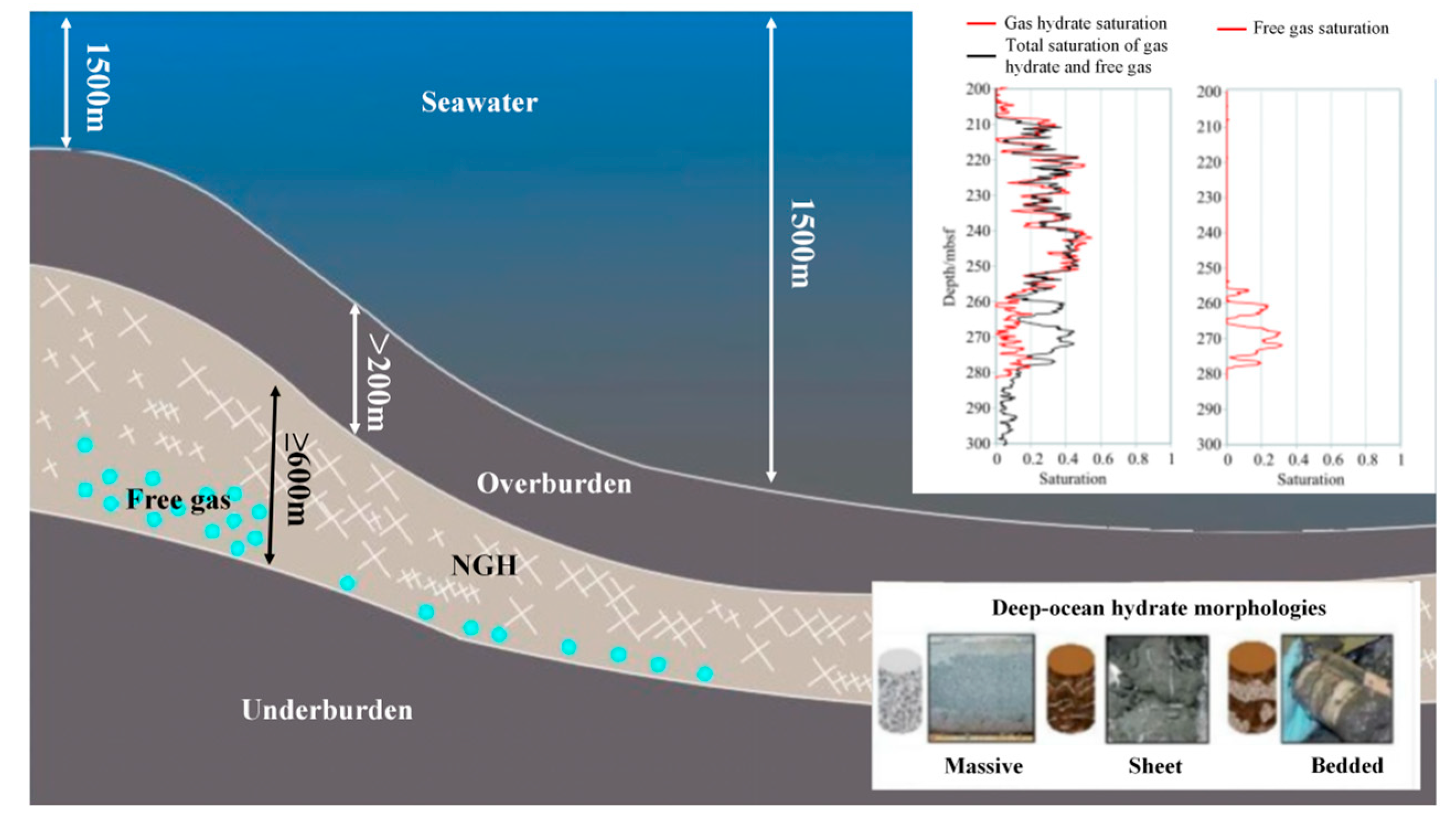
Figure 1: Schematic diagram of hydrate reservoir in Shenhu area, South China Sea [50].
3.1 Domain Discretization and Boundary Condition
Fig. 2 shows mapped mesh for hydrate bearing sediment, boundary condition and production well location schematic built in COMSOL. The geometric model is simplified to a two-dimensional model without considering the rate of pressure decay along the horizontal wellbore during production. The model is 73 m in the Y direction, ±25 m in the X direction, and 1 m in thickness, respectively. The diameter of horizontal wellbore is 0.16 m. The total number of grids are discretized into 32,488 elements. Considering phase change, mass transportation and other complex condition around the wellbore, we chose the triangular grid structure while increasing the mesh grid density near the borehole.
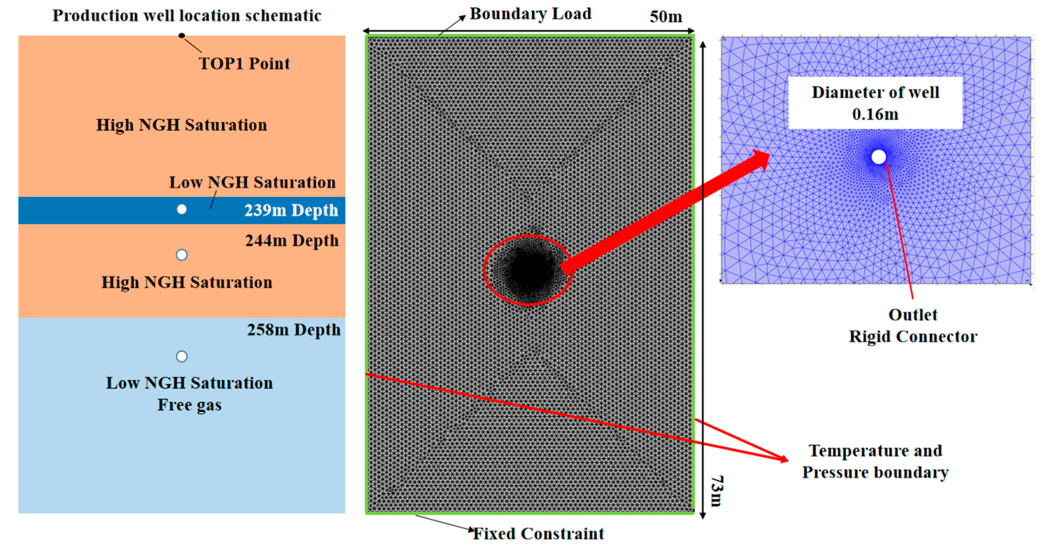
Figure 2: Mapped mesh of the NGH reservoir, boundary condition and production well location setting in the simulation model.
Since the wellhead is far from the model boundary, a constant pressure and temperature boundary with initial condition is used. And a constant production pressure is set to simulate the depressurization production process. To prevent reformation of NGH and ice formation, the temperature of the production well is set as constant value equal to initial temperature. Loading pressure of 12.07 MPa is applied to the upper boundary. TOP1 point located at the top boundary of model is set to monitor the reservoir settlement. The lower boundary is subject to a fixed constraint, while left and right boundaries are subject to roller constraints. Other parameters employed in our model are listed in Table 1.
Table 1: Initial conditions, production pressure, and well locations.
| Model Name | Run1 | Run2 | Run3 | Run4 | Run5 | Run6 | Run7 |
|---|---|---|---|---|---|---|---|
| production pressure | 4.5 MPa | 5.0 MPa | 5.5 MPa | 6.0 MPa | 6.5 MPa | ||
| Well location (Z direction) | −244 m | −244 m | −244 m | −244 m | −244 m | 239 m | 258 m |
3.2 Initial Conditions and Simulation Parameters
Prior to production of NGH, it is essential to establish the equilibrium pressure-temperature initial conditions to ensure that the simulation model’s temperature, pressure and saturation align with the actual geological conditions. Well logging results from the SH02 site indicate that the NGH deposits are located at a depth of 208 m below sea floor (mbsf) in a water column of 800 m. Due to the absence of in-situ temperature measurements, the following empirical formula is used to calculate the initial formation temperature.
Table 2: Simulation parameters [25,44,45].
| Parameters | Value | Parameters | Value |
|---|---|---|---|
| Absolute porosity/n | 0.47 | Viscosity of water/ | 1e−3 Pa·s |
| specific heat of NGH/ | 2170 J/(kg·K) | Thermal conductivity of NGH/ | 0.7 W/(m·K) |
| specific heat of water/ | 4186 J/(kg·K) | Thermal conductivity of CH4/ | 0.033 W/(m·K) |
| specific heat of CH4/ | 2191 J/(kg·K) | Thermal conductivity of water/ | 0.6 W/(m·K) |
| specific heat of sand/ | 800 J/(kg·K) | Thermal conductivity of sand/ | 1.35 W/(m·K) |
| Joule-Thomson coefficient/ | −1.5e−4 J/(kg·Pa) | Density of NGH/ | 913 kg/m3 |
| Hydration number | 5.75 | Density of water/ | 1000 kg/m3 |
| Rate constant of dissociation/ | 3.6e4 mol/(m2·Pa·s) | Density of sand/ | 2000 kg/m3 |
| Viscosity of CH4/ | 1.81e−5 Pa·s | residual volume fraction/nr | 0.248 |
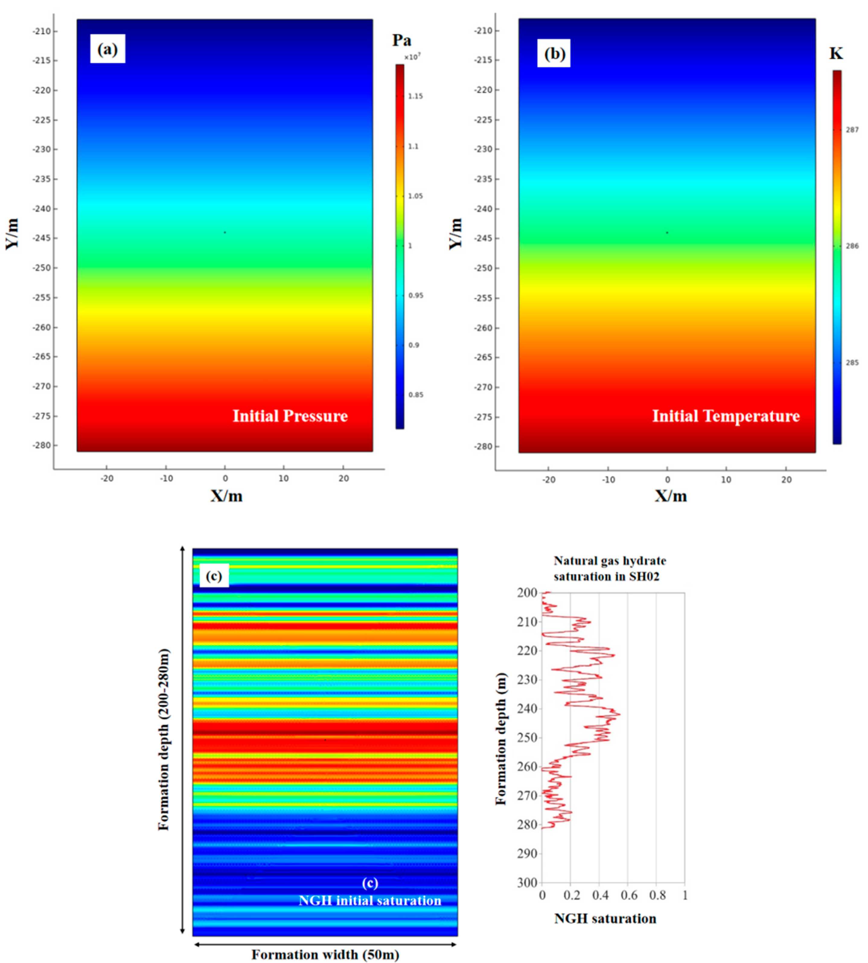
Figure 3: Initial pressure (a), temperature (b), NGH saturation (c), and logging data of SH02 [49].
4 Simulation Results and Discussion
4.1 Effect of Outlet Pressure on Gas Production Process
Fig. 4 shows the pore pressure and temperature change with production time. A significant pressure drop is observed nearby the production well in the early stage of production, and then it remains in a relatively stable state. The pressure drop area shows as a funnel shape, and its decomposition range is closely related to the production pressure; specially, a lower production pressure results in a larger decomposition area. In general, due to the low permeability of the reservoir, the decomposition area from the pressure drop remains limited even after six months of production. It is well known that the production pressure is the main factor to control the hydrate decomposition rate in depressurization method. After half a year of production, the radius of decomposition region is about 2 m with production pressure of 6.5 MPa and it is 4 m with production pressure of 4.5 MPa. Since hydrate decomposition and free gas production is an endothermic process, a decrease in production pressure accelerates both hydrate decomposition and gas production, leading to a more pronounced temperature drop near the wellbore.
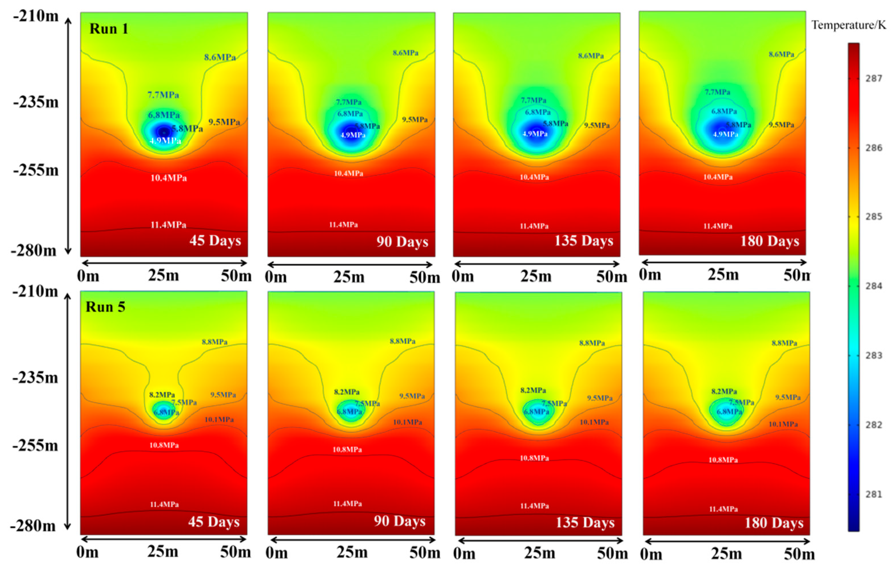
Figure 4: Formation pore pressure and temperature change with production time.
Fig. 5 shows the gas and water production rate for per unit well length with different production pressure. Since there is free gas in the NGH reservoir, and no drainage depressurization process in the numerical simulation, water and gas can be produced instantly at the beginning of production. It shows a high initial gas production rate, then rapid decayed for the consumption of free gas. During the initial production phase, the migration of free gas and water near the wellbore towards the wellbore leads to an enhanced production rate; however, subsequent migration of free gas and water from low permeability formations is hindered, resulting in a rapid decline in production rate [51]. As the production progresses, the system pressure gradually decreases due to the discharge of free gas and water. Once it reaches the equilibrium pressure of natural gas hydrates (NGH), NGH decomposition occurs to supplement the gas source, resulting in enhancement in production rate. It has been reported that the average gas production rate of the second hydrate production test in the Shenhu area of the South China Sea is 2.9 × 10⁴ m3/day [49]. Under similar conditions with a horizontal well length, simulation results indicate a production rate of 3.8 × 10⁴ m3/day at an outlet pressure of 6.5 MPa, which aligns closely with field data. As the production pressure is reduced to 4.5 MPa, the gas and water production rates increase to 2 times and the produced cumulative gas increase to 3 times. Therefore, reducing production pressure during the production can improve gas production effectively.
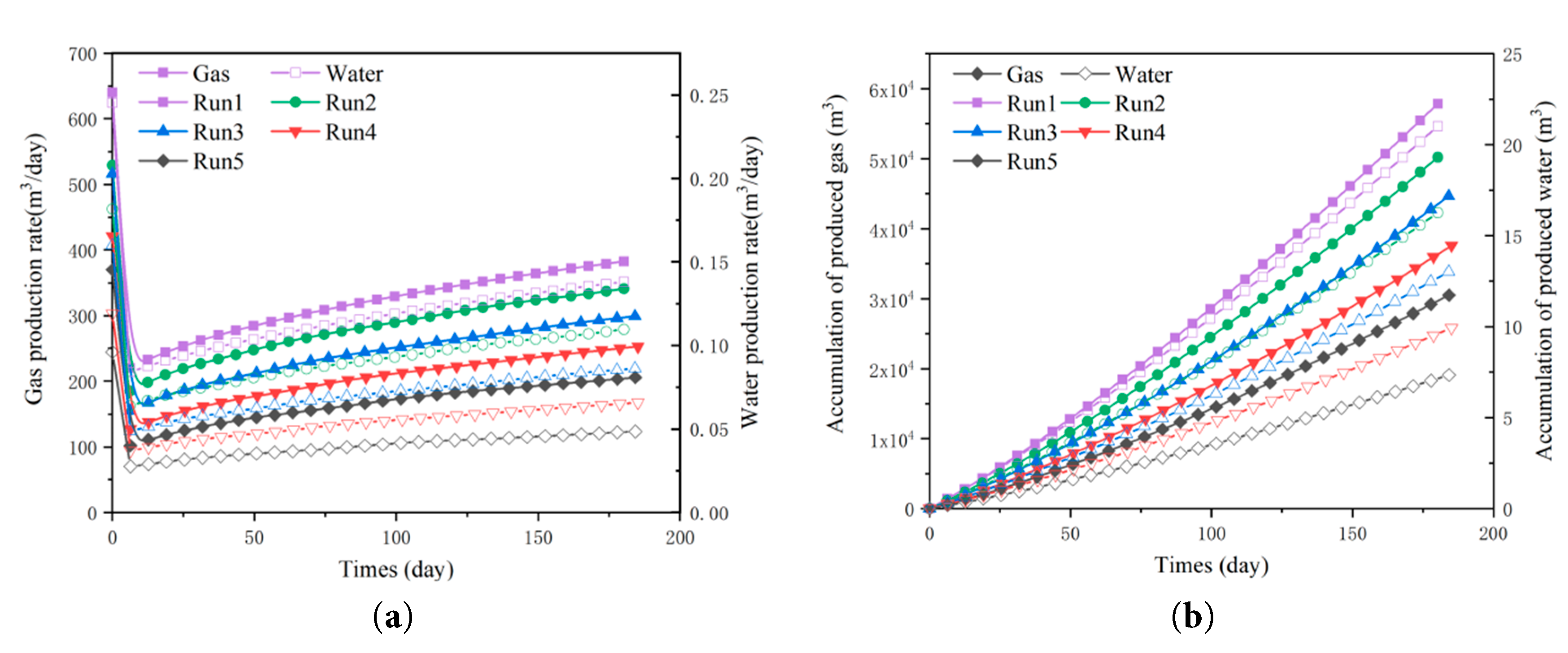
Figure 5: Gas and water production rate (a), accumulation of produced gas and water (b) 1 m well length with different production pressure.
Fig. 6 shows NGH saturation change with production time. Since the NGH saturation reservoir is stratified, the degree of hydrate saturation within the pore increases inversely with respect to the permeability, the permeability is diminished as a result of the presence of NGH in the pore. The production pressure drop can be transmitted quickly into depth of the low Sh area, which shows a significant ahead of NGH decomposition front in low Sh layers than that in high Sh region. Since production pressure is the main factor to control NGH decomposition rate in the production process, the radius of decomposition region is about 2 m with production pressure of 6.5 MPa after half a year of production, and it is 6 m with production pressure of 4.5 MPa. Additionally, there are a few secondary hydrates occurring near the hydrate dissociation front. The heat absorption associated with NGH dissociation alters the pressure-temperature conditions of phase equilibrium, leading to the reformation of NGH.
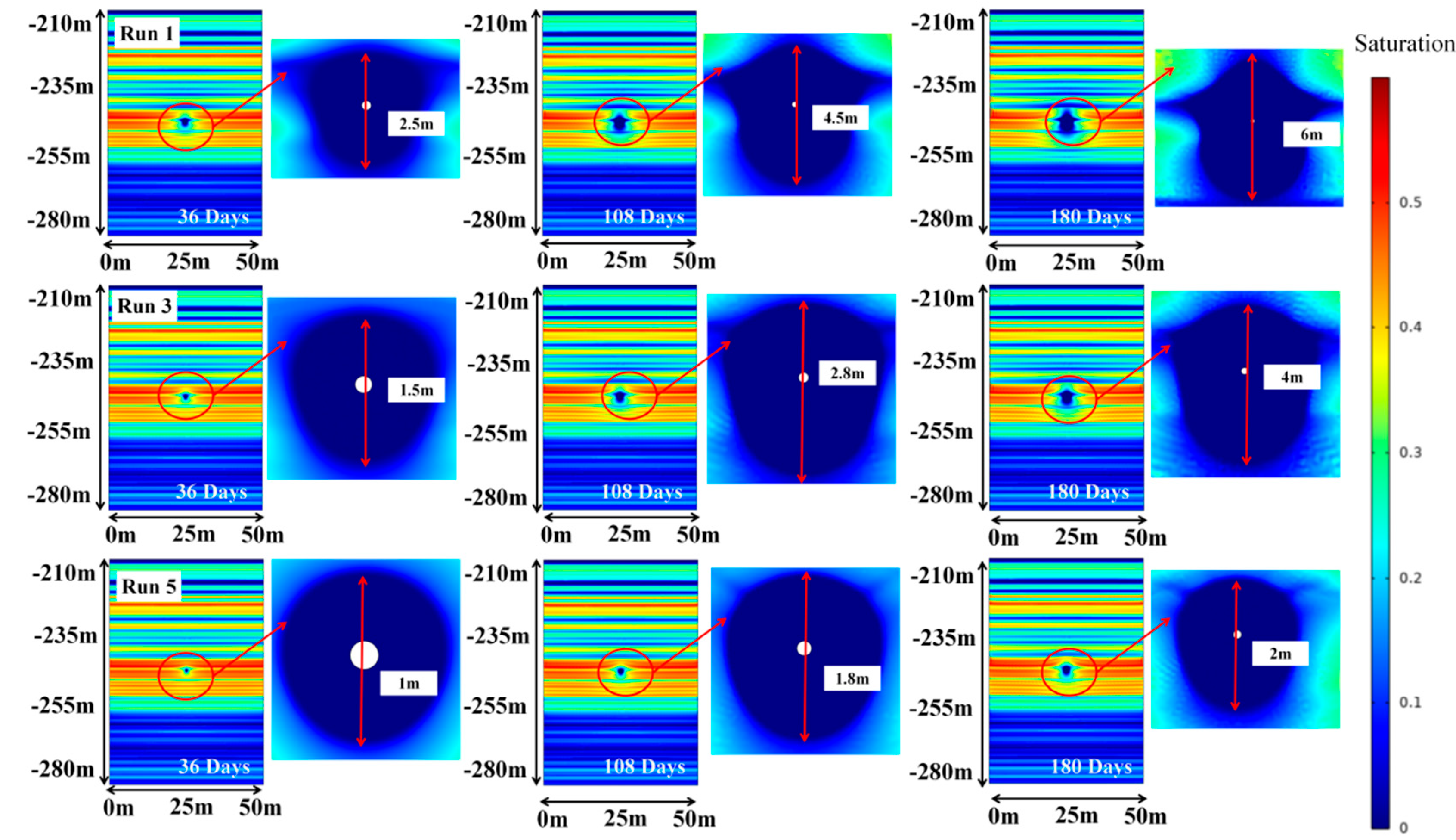
Figure 6: NGH saturation variation with production time and different production pressure.
Fig. 7 shows the reservoir settlement characters with different production pressure. The primary settlement is concentrated in the upper deposit around the wellbore, with wellbore settlement values of 0.032 m and 0.018 m observed at pressures of 4.5 MPa and 6.5 MPa, respectively. Meanwhile, the settlement of TOP1 point in Run1 reaches to nearly 0.1 m with production pressure of 4.5 MPa. And the settlement curves show that settlement displacement will continue to increase with the NGH production. The top boundary exhibits a U-shaped sag over a production period of 180 days. The settlement rate of formation refers to subsidence in per unit time. Its maximum value occurs at the beginning of production and decreasing with production time, which is very similar to the gas production rate curve. Lower production pressures induce greater settlement and sag in the top boundary, increasing likelihood of effective stress concentration and geological landslide. This is corroborate by the settlement rate observed at the upper boundary. With the free gas and water discharged, the mechanical weakness of reservoir caused by NGH decomposition become the main reason for reservoir settlement. And the settlement rate shows a gradual decline with the production time.
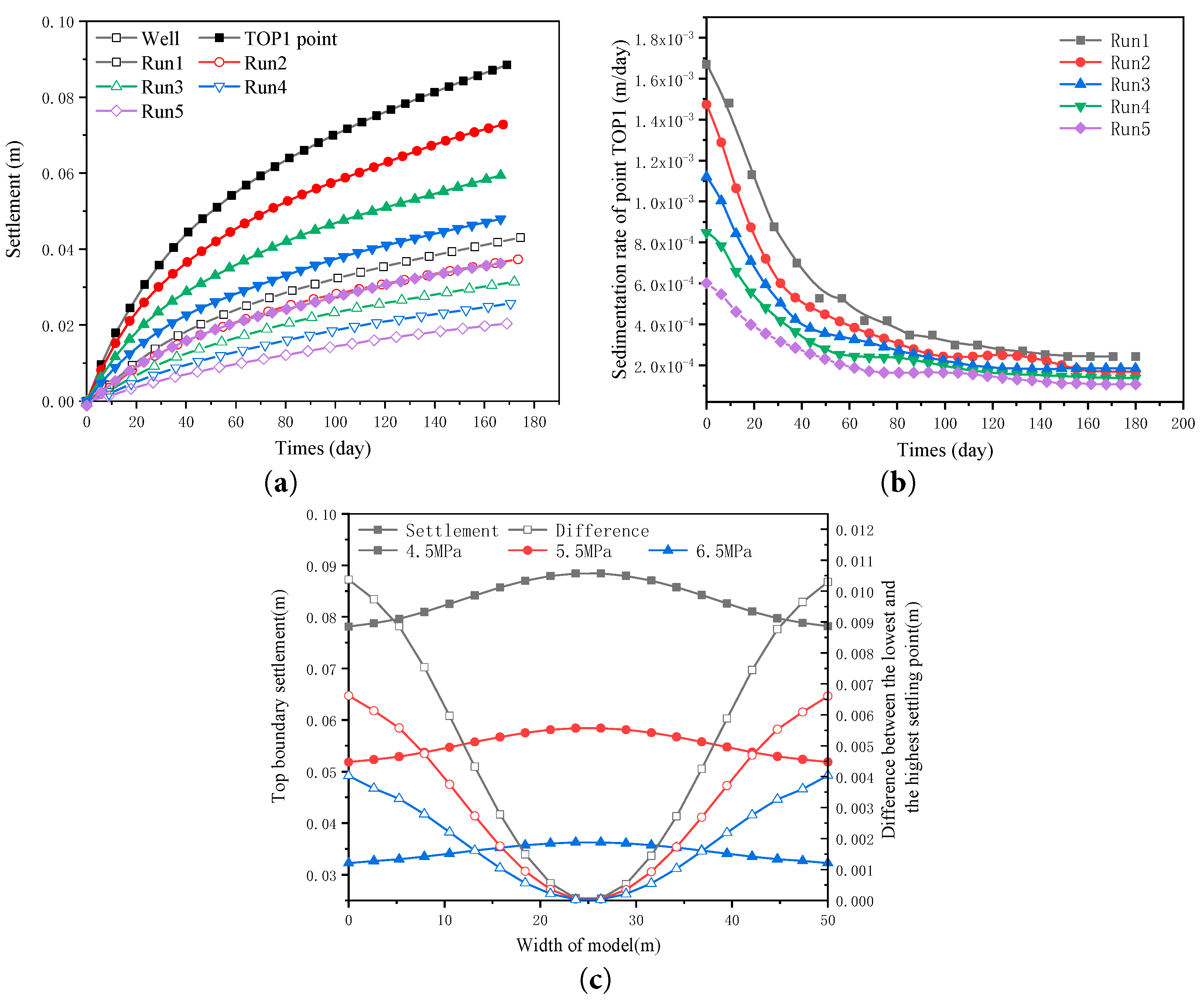
Figure 7: Reservoir settlement characteristics with different production pressure. (a) Settlement, (b) Sedimentation rate (c) Top boundary settlement.
4.2 Influence of Horizontal Well Location
Fig. 8 shows NGH saturation distribution contours with different well location.
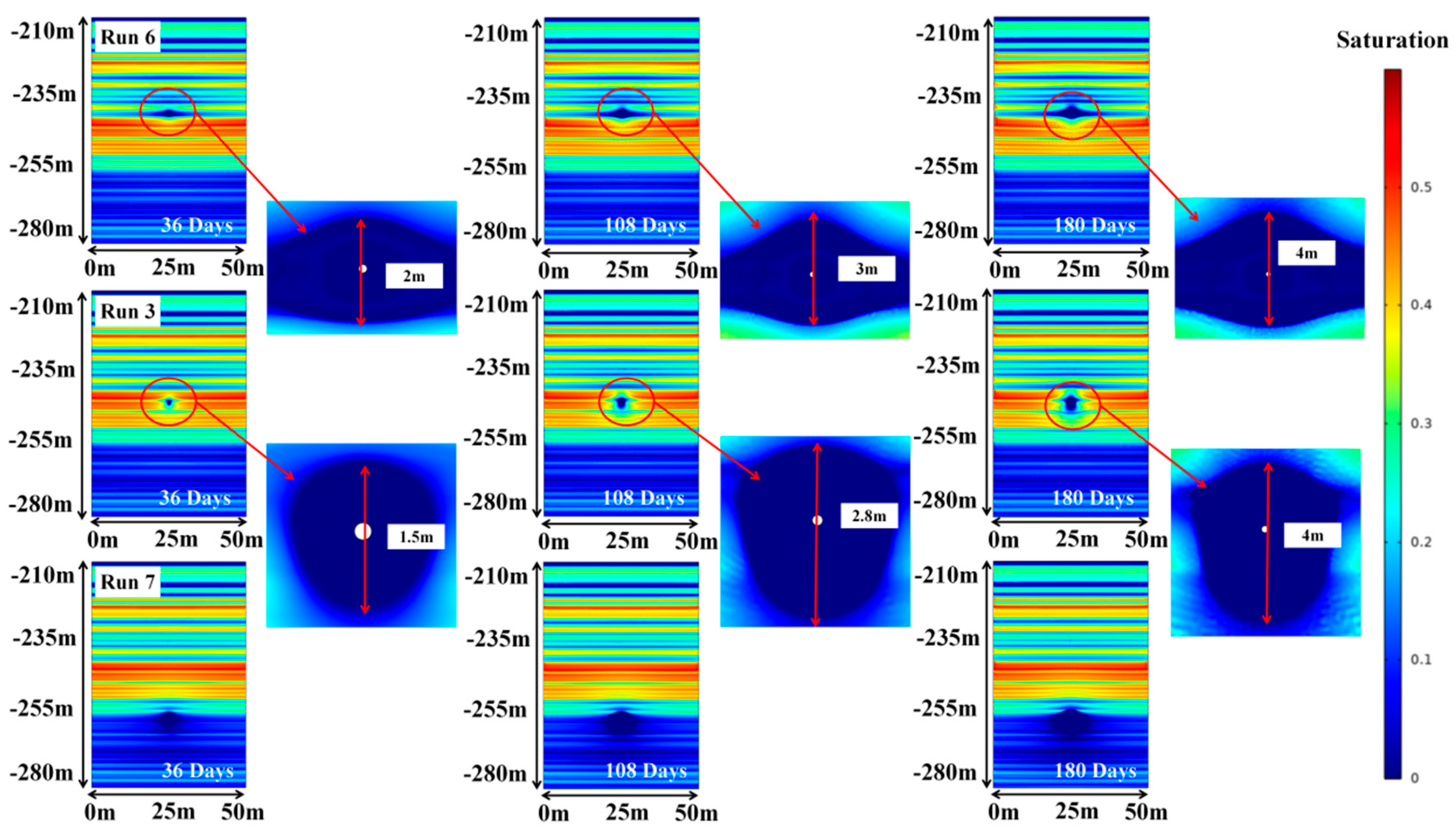
Figure 8: NGH saturation distribution contours with different well location.
The NGH saturation exerts a significant influence on the permeability, induces regional distribution of hydrate decomposition. The decomposition shape of the Run6 model starts with the wellbore and diffuses along the low saturation hydrate layer. The decomposition area forms a diamond-shaped distributed after approximately 180 days, and the movement of the decomposition interface in the lower layer of the well site is slower due to higher NGH saturation of formation. The decomposition interface of the Run3 exhibits an approximate circular shape with a radius ranging from 4 m after a period of 180 days. The occurrence of uniformly distributed, highly saturated hydrate layers surrounding the wellbore is responsible for this phenomenon. The well location of the Run7 model is located within the free gas layer, thereby facilitating the most rapid decomposition of hydrates and resulting in a largest decomposition area.
Fig. 9 illustrates gas and water production rates and accumulated production for different well location with a well length of 1 m. Initially, production rates are high at the onset of production, rapidly decreasing to a lower value, then gradually rising and stabilizing. During the decline stage of production rate, Run3 exhibits the lowest rate while Run7 is the highest. At the production enhancement stage, Run3’s rate gradually aligns with that of Run6, whereas Run7’s rate remains relatively constant. The wellbore of Run3, located in a high-saturation hydrate formation, impedes free gas and water migration due to elevated saturation. However, the wellbores of Run6 and Run7, located in lower-saturation hydrate and free gas zone, respectively, indicates the greater permeability, facilitating fluid migration to the wellbores. In the mid-to-late production stages, gas from hydrate dissociation sustains decomposition rate, resulting in a higher recovery rate for Run3 compared to Run6 in later stages. The cumulative gas production of Run7 is highest, as it includes free gas, hydrate-derived gas and dissolved gas from pore liquid.
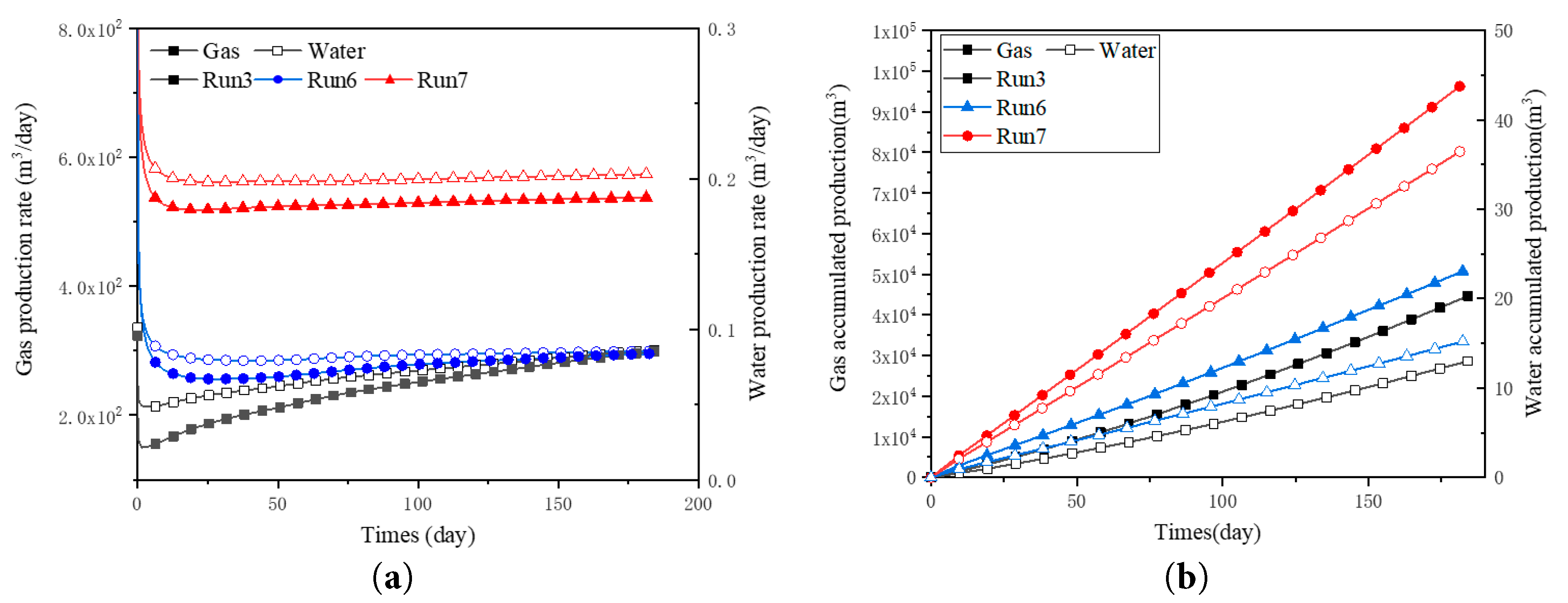
Figure 9: Gas and water production rate (a) and accumulated production (b) with different well location for 1 m well length.
Fig. 10 shows reservoir settlement characteristics under different well locations. It is shown that after 30 days production, the settlement and settlement rate of TOP1 point in the Run3 surpasses that of the Run6. The production well in Run6 is located in the low Sh layer where with relatively high permeability, and the pore pressure drops significantly quicker than Run3, then leading to a faster settlement in Run6. With the continuous gas production, the hydrate decomposition within the pressure drop influence range becomes the main gas source. The pressure drop influence range in Run6 is significantly larger than that in Run3, and the pressure drop gradient at local points is smaller than that in Run3, resulting in a smaller amount of hydrate decomposition at local points in Run6 and a smaller local settlement for formation weakening caused by hydrate decomposition. The settlement of Run7 is the largest among all cases after 180 days gas production. Since the pore pressure drop gradient is more evenly distributed due to the wellbore located in the free gas region in Run7, it shows a minimum sag in its top boundary, which is benefit to prevent the formation of tension fractures caused by uneven settlement. The settlement of Run6 is the smallest among all, while exhibiting the largest sag in its top boundary. And the settlement of Run3 is comparatively lower than that of Run6 due to its location in a highly saturated formation with enhanced strength. Above results show that well location would significantly affect the settlement and gas characteristics of the NGH reservoir. Although locating the production well in the overlying free gas layer would lead to a largest settlement, the formation uneven settlement is minimal in this way, which can effectively reduce the tensile fractures development caused by the uneven settlement. Meanwhile, the gas production rate of this wellbore arrangement can significantly increase the gas production rate.
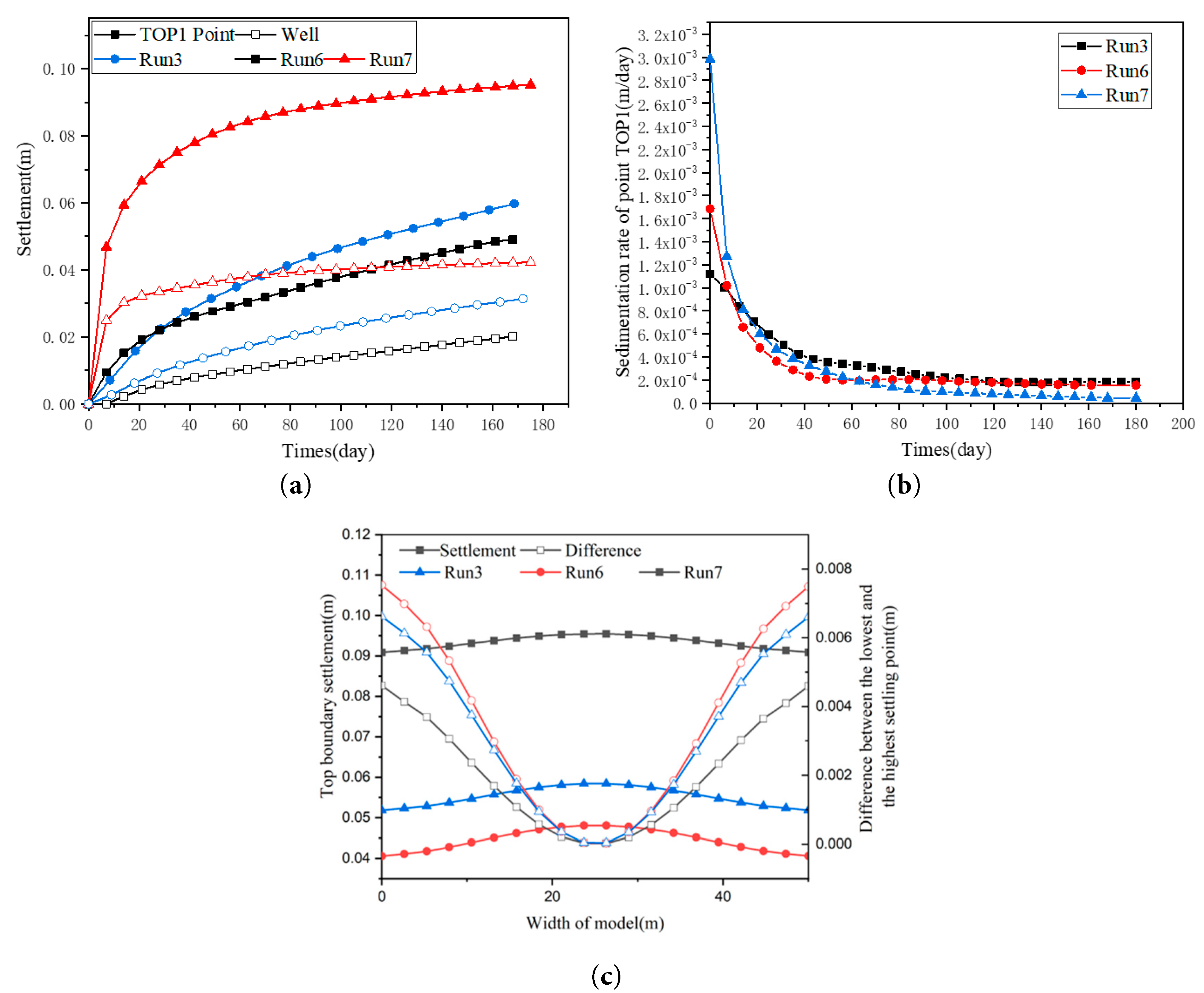
Figure 10: Reservoir settlement characteristics under different well location (a) Displacement of point TOP1, (b) Sedimentation rate of point TOP1, (c) Displacement of upper boundary.
This study investigates the settlement behavior of horizontal wellbores in natural gas hydrate (NGH) reservoirs with heterogeneous hydrate distributions. The influences of well placement under various production pressures and single-well production conditions on both gas production and formation settlement are analyzed. Results shows that although lower production pressures enhance productivity, but also lead to increased formation settlement and a higher risk of tensile fractures. Previous studies have also indicated that excessively low production pressures may promote secondary hydrate formation, thereby impeding gas flow [52]. Thus, it is crucial to optimize production pressure based on specific NGH reservoir characteristics. Adjusting the horizontal well position can help compensate for the production deficiency caused by high outlet pressure. The optimal configuration appears to place the well near free gas zones within low-saturation hydrate formations. This strategy not only improves gas production but also mitigates uneven settlement, thereby reducing the potential for tensile fracture development.
Acknowledgement:
Funding Statement: This work is financially supported by the State Key Research Development Program of China (Grant No. 2021YFC2800905-02), the National Natural Science Foundation of China (Grant No. 52304208), which are gratefully acknowledged.
Author Contributions: Lijia Li: Conceptualization, Methodology, Investigation, Writing—Original Draft. Shu Liu: Software, Formal analysis, Data Curation. Xiaoliang Huang: Writing Review and Editing. Zhilin Qi: Resources, Validation, Investigation, Writing Review. All authors reviewed approved the final version of the manuscript.
Availability of Data and Materials: The datasets used and analyzed during the current study are available from the corresponding author on reasonable request.
Ethics Approval: Not applicable.
Conflicts of Interest: The authors declare no conflicts of interest.
Nomenclature
| As | Dissociation surface area of hydrate particles of unit volume |
| Cp.w | Capillary capacity of water |
| Pg | Pore pressure of methane gas |
| P0 | Entry pressure |
| Critical pressure | |
| n0 | Initial porosity |
| specific heat, i = h, w, g, s | |
| Gas compression coefficient | |
| Absolute permeability | |
| Production rate of methane gas | |
| Joule-Thomson coefficient | |
| NH | Hydration number |
| Rate constant of dissociation | |
| Dynamic viscosity, i = g, w | |
| T | Temperature |
| Effective stress | |
| Stress tensor | |
| Internal friction angle | |
| Pinitial | Initial Pressure |
| Pout | Outlet pressure |
| Toutlet | Outlet temeprature |
| uinitial | Initial settlement |
| Ageo | Surface areas to volume ratio of hydrate particles |
| Pc | Capillary tube pressure |
| Pw | Pore pressure of water |
| Pe | Gas pressure of three-phase equilibrium state of hydrate |
| nwg | Effective porosity |
| n | Porosity |
| Volumetric strain of sediment | |
| Thermal conductivity, i = h, g, w, s | |
| Relative permeability, i = g, w | |
| Enthalpy of the methane decomposition process | |
| Density, i = h, w, s | |
| Kinetic energy | |
| Decomposition constant of NGH | |
| Si | Saturation, i = h, g, w |
| | Critical temperature |
| vi | Darcy’s velocity tensor, i = g, w |
| Total strain tensor | |
| Cohesion | |
| Pwell | Pressure of well |
| Tinitial | Initial temperature |
| uoutlet | Settlement of well |
| F | Formation weight stress |
The energy equation is written in the form of enthalpy and temperature.
For gas, need to consider the second term of the right side of Eq. (A2), that is, Joule-Thomson throating coefficient,
Considering (A2), the first term of the left side of Eq. (A1) gets:
Then, the second term of the left side of Eq. (A1) can be written as:
Add (A3), (A7), substituting into (A1), gets
Considering Eq. (A2), (A8) can be written as:
Considering the energy balance conditions for hydrate dissociation:
References
1. Ul HI , Qasim A , Lal B , Zaini DB . Mini review on environmental issues concerning conventional gas hydrate inhibitors. Process Saf Prog. 2022; 41( S1): S129– 34. doi:10.1002/prs.12325. [Google Scholar] [CrossRef]
2. Li YX , Zhang ZB , Li SD . Enhanced strategies for depressurization in offshore natural gas hydrate exploitation: An in-depth investigation into pathway optimization and production stability mechanisms. Mar Pet Geol. 2024; 170: 107107. doi:10.1016/j.marpetgeo.2024.107107 [Google Scholar] [CrossRef]
3. Majumdar D , Gupta M , Shastri Y , Mahajani SM . Environmental and economic assessment of gas production from gas hydrate reserves in Krishna-Godavari basin in the Indian offshore. Sustain Energy Technol Assess. 2023; 56: 103050. doi:10.1016/j.seta.2023.103050. [Google Scholar] [CrossRef]
4. Gaidukova O , Misyura S , Strizhak P . Key Areas of Gas Hydrates Study: Review. Energies. 2022; 15( 5): 1799. doi:10.3390/en15051799. [Google Scholar] [CrossRef]
5. Kondori J , Zendehboudi S , Hossain ME . A review on simulation of methane production from gas hydrate reservoirs: Molecular dynamics prospective. J Pet Sci Eng. 2017; 159: 754– 72. doi:10.1016/j.petrol.2017.09.073. [Google Scholar] [CrossRef]
6. Lee S , Park S , Lee Y , Seo Y . Thermodynamic and 13C NMR spectroscopic verification of methane-carbon dioxide replacement in natural gas hydrate. Chem Eng J. 2013; 225: 636– 40. doi:10.1016/j.cej.2013.03.117. [Google Scholar] [CrossRef]
7. Liang YP , Tan YT , Luo YJ , Zhang YY , Li B . Progress and challenges on gas production from natural gas hydrate-bearing sediment. J Clean Prod. 2020; 261: 121061. doi:10.1016/j.jclepro.2020.121061. [Google Scholar] [CrossRef]
8. Liu WG , Luo TT , Li YH , Song YC , Zhu Y , Liu Y , et al. Experimental study on the mechanical properties of sediments containing CH4 and CO2 hydrate mixtures. J Nat Gas Sci Eng. 2015; 32: 20– 7. doi:10.1016/j.jngse.2016.03.012. [Google Scholar] [CrossRef]
9. Ye HY , Chen JY , Yao YX , Dong P , Chen DY , Niu MY , et al. How injecting CO2 enhances marine natural gas hydrate exploitation: Review and prospect. Mar Pet Geol. 2024; 170: 107107. doi:10.1016/j.rser.2025.116011. [Google Scholar] [CrossRef]
10. Almenningen S , Gauteplass J , Hauge LP , Barth T , Fernø MA , Ersland G . Measurements of CH4 and CO2 relative permeability in hydrate-bearing sandstone. J Pet Sci Eng. 2019; 177: 880– 8. doi:10.1016/j.petrol.2019.02.091. [Google Scholar] [CrossRef]
11. An SH , Le VS , Chon BH . Production characteristics of gas hydrate reservoirs associated with steam injection and depressurization rate. Int J Oil Gas Coal Technol. 2018; 19( 3): 296– 315. doi:10.1504/IJOGCT.2018.095574. [Google Scholar] [CrossRef]
12. Yang X , Sun CY , Yuan Q , Ma PC , Chen GJ . Experimental study on gas production from methane hydrate-bearing sand by hot-water cyclic injection. Energy Fuels. 2010; 24( 11): 5912– 20. doi:10.1021/ef100367a. [Google Scholar] [CrossRef]
13. Zhao E , Hou J , Ji Y , Liu Y , Bai Y . Enhancing gas production from Class II hydrate deposits through depressurization combined with low-frequency electric heating under dual horizontal wells. Energy. 2021; 233: 121137. doi:10.1016/j.energy.2021.121137. [Google Scholar] [CrossRef]
14. Lee T , Ahn T , Park S . Simulation study of gas hydrate production using various thermal stimulation methods in the Ulleung Basin of the Korean East Sea. Pet Sci Technol. 2025: 1– 20. doi:10.1080/10916466.2025.2465879. [Google Scholar] [CrossRef]
15. Li L , Li X , Wang Y , Luo Y , Li B . Analyzing the applicability of in situ heating methods in the gas production from natural gas hydrate-bearing sediment with field scale numerical study. Energy Rep. 2020; 6: 3291– 302. doi:10.1016/j.egyr.2020.11.208. [Google Scholar] [CrossRef]
16. Feng JC , Wang Y , Li XS . Entropy generation analysis of hydrate dissociation by depressurization with horizontal well in different scales of hydrate reservoirs. Energy. 2017; 125: 62– 71. doi:10.1016/j.energy.2017.02.104. [Google Scholar] [CrossRef]
17. Liu LP , Sun ZL , Zhang L , Wu NY , Qin YC . Progress in global gas hydrate development and production as a new energy resource. Acta Geol Sin Engl. 2019; 93( 3): 731– 55. doi:10.1111/1755-6724.13876. [Google Scholar] [CrossRef]
18. Ye JL , Qin XW , Xie WW , Lu H , Ma B , Qiu H , et al. The second natural gas hydrate production test in the South China Sea. China Geol. 2020; 2: 197– 209. doi:10.31035/cg2020043. [Google Scholar] [CrossRef]
19. Pandey MR , Priest JA , Hayley JL . Influence of test conditions and soil properties on the geomechanical response of hydrate-bearing sands. Can Geotech J. 2025; 62: 0378. doi:10.1139/cgj-2023-0378. [Google Scholar] [CrossRef]
20. Yan CL , Ren X , Cheng YF , Song BJ , Li Y , Tian WQ . Geomechanical issues in the exploitation of natural gas hydrate. Gondwana Res. 2020; 81: 403– 22. doi:10.1016/j.gr.2019.11.014. [Google Scholar] [CrossRef]
21. Rydzy MB . The effect of hydrate formation on the elastic properties of unconsolidated sediment [ dissertation]. Golden, CO, USA: Colorado School of Mines; 2014. p. 127. [Google Scholar]
22. Chuvilin EM , Bukhanov BA , Grebenkin S , Doroshin VV , Iospa AV . Shear strength of frozen sand with dissociation pore methane hydrate: An experimental study. Cold Reg Sci Technol. 2018; 153: 101– 5. doi:10.1016/j.coldregions.2018.04.013. [Google Scholar] [CrossRef]
23. Wang AW , Zhang CY , Luo TT , Ma CZ , Zhao Y , You ZS , et al. Mechanical properties of consolidated water-saturated natural gas hydrate-bearing silty-clayey sediments under undrained shearing conditions. Int J Hydrogen Energy. 2025; 99: 996– 1009. doi:10.1016/j.ijhydene.2024.12.271. [Google Scholar] [CrossRef]
24. Pandey MR , Priest JA , Hayley JL . The Influence of Particle Size and Hydrate Formation Path on the Geomechanical Behavior of Hydrate Bearing Sands. Energies. 2022; 15( 24): 9632. doi:10.3390/en15249632. [Google Scholar] [CrossRef]
25. Li LJ , Li XS , Wang Y , Huang XL , Qi ZL , Chen Z . Study on the settlement characteristics of hydrate bearing sediment caused by gas production with the depressurization method. Energy Fuels. 2024; 38( 7): 5810– 21. doi:10.1021/acs.energyfuels.3c04197. [Google Scholar] [CrossRef]
26. Yoneda J , Suzuki K , Oshima M , Muraoka M , Jin Y . Empirical evaluation of the strength and deformation characteristics of natural and synthetic gas hydrate-bearing sediments with different ranges of porosity, hydrate saturation, effective stress, and strain rate. J Vis Exp. 2024; 11: 3. doi:10.1186/s40645-024-00606-1. [Google Scholar] [CrossRef]
27. Priest JA , Best AI , Clayton CRI . A laboratory investigation into the seismic velocities of methane gas hydrate-bearing sand. J Geophys Res. 2005; 110: B04102. doi:10.1029/2004JB003259. [Google Scholar] [CrossRef]
28. Kim J , Seol Y , Dai S . The coefficient of earth pressure at rest in hydrate-bearing sediments. Acta Geotech. 2021; 16( 9): 2729– 39. doi:10.1007/s11440-021-01174-0. [Google Scholar] [CrossRef]
29. Gan BC , Li ZD , Zhang HX , Zhang YZ , Huo WX , Li Z , et al. Optimizing hydrate extraction: Balancing stability and production efficiency. Fuel. 2025; 384: 134088. doi:10.1016/j.fuel.2024.134088. [Google Scholar] [CrossRef]
30. Li JW , Zhang Y , Di SJ , Lin L , Zhou Y . Research on hydrate-bearing reservoir deformation and wellbore wall stability during natural gas hydrate exploitation. Geomech Energy Environ. 2023; 34: 100458. doi:10.1016/j.gete.2023.100458. [Google Scholar] [CrossRef]
31. Myshakin E , Garapati N , Seol Y , Gai X , Boswell R , Ohtsuki S , et al. Numerical Simulations of Depressurization-Induced Gas Hydrate Reservoir (B1 Sand) Response at the Prudhoe Bay Unit Kuparuk 7-11-12 Pad on the Alaska North Slope. Energy Fuels. 2022; 36( 5): 2542– 60. doi:10.1021/acs.energyfuels.1c04099. [Google Scholar] [CrossRef]
32. Lele AF , Kuznik F , Rammelberg HU , Schmidt T , Ruck WKL . Thermal decomposition kinetic of salt hydrates for heat storage systems. Appl Energy. 2015; 154: 447– 58. doi:10.1016/j.apenergy.2015.02.011. [Google Scholar] [CrossRef]
33. Jiang MJ , Lu YC , Wang HN , Chen YR . Multi-field coupling analysis of mechanical responses in methane hydrate exploitation with a practical numerical approach combining T+H with DEM. Comput Geotech. 2024; 166: 105978. doi:10.1016/j.compgeo.2023.105978. [Google Scholar] [CrossRef]
34. Zhao XL , Wang ZL , Zhao YZ , Zuo JQ , Li P , Liang W , et al. Coupled thermal-hydrodynamic-mechanical numerical simulation of natural gas hydrate horizontal well depressurization production: method and application in the South China Sea. Nat Gas Ind B. 2022; 9( 6): 548– 60. doi:10.1016/j.ngib.2022.11.005. [Google Scholar] [CrossRef]
35. Cheng FB , Sun X , Wu P , Chen ZX , Yu T , Liu WG , et al. A Fully Coupled Thermo-Hydro-Mechanical-Chemical Model for Methane Hydrate Bearing Sediments Considering the Effect of Ice. J Mar Sci Eng. 2023; 11: 766. doi:10.3390/jmse11040766. [Google Scholar] [CrossRef]
36. Jiang YJ , Ma XZ , Cheng XZ . Numerical simulation on natural gas hydrate depressurization production considering sediment compression effects. Energy. 2024; 301: 131745. doi:10.1016/j.energy.2024.131745. [Google Scholar] [CrossRef]
37. Li YX , Zhang ZB , Li SD , Li X , Lu C . Numerical investigation of the depressurization exploitation scheme of offshore natural gas hydrate: enlightenments for the depressurization amplitude and horizontal well location. Energy Fuels. 2023; 37( 14): 10706– 20. doi:10.1021/acs.energyfuels.3c01223. [Google Scholar] [CrossRef]
38. Ghezzehei TA , Kneafsey TJ , Su GW . Correspondence of the Gardner and van Genuchten-Mualem relative permeability function parameters. Water Resour Res. 2007; 43( 10): W10417. doi:10.1029/2006WR005339. [Google Scholar] [CrossRef]
39. Amyx JW , Bass DM , Whiting RL . Petroleum reservoir engineering physical properties. New York, NY, USA: McGraw-Hill; 1960. [Google Scholar]
40. Kim HC , Bishnoi PR . Kinetics of methane hydrate decomposition. Chem Eng Sci. 1987; 42: 1645– 53. doi:10.1016/0009-2509(87)80169-0. [Google Scholar] [CrossRef]
41. Clarke M , Bishnoi PR . Determination of the activation energy and intrinsic rate constant of methane gas hydrate decomposition. Can J Chem Eng. 2001; 79( 1): 143– 7. doi:10.1002/cjce.5450790122. [Google Scholar] [CrossRef]
42. Kumar A , Maini B , Bishnoi PR , Clarke M , Zatsepina O , Srinivasan S . Experimental determination of permeability in the presence of hydrates and its effect on the dissociation characteristics of gas hydrates in porous media. J Pet Sci Eng. 2010; 70: 114– 22. doi:10.1016/j.petrol.2009.10.005. [Google Scholar] [CrossRef]
43. Deng XF , Feng JW , Pan SW , Wang ZY , Zhang JB , Chen WQ . An improved model for the migration of fluids caused by hydrate dissociation in porous media. J Pet Sci Eng. 2020; 188: 106876. doi:10.1016/j.petrol.2019.106876. [Google Scholar] [CrossRef]
44. Soga K , Klar A . Coupled deformation-flow analysis for methane hydrate production by depressurized wells. In: Proceedings of the 3rd International Biot Conference on Poromechanics; 2005 May 24–27; Norman, OK, USA. doi:10.1201/NOE0415380416.ch98. [Google Scholar] [CrossRef]
45. Deng XF , Pan SW , Zhang JB , Wang ZY , Jiang ZY . Numerical investigation on abnormally elevated pressure in laboratory-scale porous media caused by depressurized hydrate dissociation. Fuel. 2020; 271: 117679. doi:10.1016/j.fuel.2020.117679. [Google Scholar] [CrossRef]
46. Miyazaki K , Masui A , Yamamoto Y , Ogata Y , Aoki K , Yamaguchi T . Investigation of deformation mechanism for methane hydrate sediment based upon mechanical properties in unloading and reloading process under triaxial compression. In: Proceedings of the 8th International Offshore and Polar Engineering Conference; 2009 Jul 6–11; Osaka, Japan. [Google Scholar]
47. Dhakal S , Gupta I . Gas hydrates reserve characterization using thermo-hydro-mechanical numerical simulation: a case study of green canyon 955, gulf of Mexico. Energies. 2023; 16( 7): 3275. doi:10.3390/en16073275. [Google Scholar] [CrossRef]
48. Masui A , Haneda H , Ogata Y . Effects of methane hydrate formation on shear strength of synthetic methane hydrate sediments. In: Proceedings of the 15th International Offshore and Polar Engineering Conference; 2005 Jun 19–24; Seoul, Republic of Korea. [Google Scholar]
49. Deng W , Liang J , Kuang Z , Xie Y , Yan P . Estimation of Gas Hydrate Saturation Regarding the Hydrate Morphology in Hydrate-Bearing Sands in the Qiongdongnan Basin, South China Sea. Pure Appl Geophys. 2023; 180: 2757– 73. doi:10.1007/s00024-023-03299-7. [Google Scholar] [CrossRef]
50. Qin XW , Lu JA , Lu HL , Qiu HJ , Liang JQ , Kang DJ , et al. Coexistence of natural gas hydrate, free gas and water in the gas hydrate system in the Shenhu Area, South China Sea. China Geol. 2020; 2: 210– 20. doi:10.31035/cg2020038. [Google Scholar] [CrossRef]
51. Ye HY , Chen JY , Yao YX , Chen DY , Wu XZ , Li DY , et al. Gas recovery from low-permeability muddy silt gas hydrate reservoirs by depressurization coupled with hot water injection: Impact of hydro-lock effect. Energy. 2025; 316( 1): 134413. doi:10.1016/j.energy.2025.134413. [Google Scholar] [CrossRef]
52. Li LJ , Li XS , Wang Y , Qin CZ , Li B , Luo YJ , et al. Investigating the interaction effects between reservoir deformation and hydrate dissociation in hydrate-bearing sediment by depressurization method. Energies. 2021; 14: 548. doi:10.3390/en14030548. [Google Scholar] [CrossRef]
Cite This Article
 Copyright © 2026 The Author(s). Published by Tech Science Press.
This work is licensed under a Creative Commons Attribution 4.0 International License , which permits unrestricted use, distribution, and reproduction in any medium, provided the original work is properly cited.
 Downloads
 Citation Tools