
 Submit a Paper
 Propose a Special lssue
 Open Access
ARTICLE
Mechanical Analysis of Free-Standing Cold-Water Pipe for Ocean Thermal Energy Conversion
1 Guangzhou Marine Geological Survey, China Geological Survey, Guangzhou, 511458, China
2 Guangdong Nanyou Holding Group Co., Ltd., Guangzhou, 510075, China
* Corresponding Author: Bo Ning. Email:
Fluid Dynamics & Materials Processing 2026, 22(1), 5 https://doi.org/10.32604/fdmp.2026.074335
Received 09 October 2025; Accepted 23 December 2025; Issue published 06 February 2026
 View Full Text
 Download PDF
Abstract
As a controllable power generation method requiring no energy storage, Ocean Thermal Energy Conversion (OTEC) technology demonstrates characteristics of abundant reserves, low pollution, and round-the-clock stable operation. The free-standing cold-water pipe (CWP) in the system withstands various complex loads during operation, posing potential failure risks. To reveal the deformation and stress mechanisms of OTEC CWPs, this study first analyzes wave particle velocity and acceleration to determine wave loads at different water depths. Based on the Euler-Bernoulli beam model, a quasi-static load calculation model for OTEC CWPs was established. The governing equations were discretized using the finite difference method, and matrix equations were solved to analyze bending deformation, bending moments, and surface stresses at discrete points along the pipe. Results indicate that water depths within 50 m represent a critical zone where wave particle velocity, acceleration, and wave loads exhibit significant variations in harmonic patterns, while beyond 50 m depth wave loads decrease linearly. Ocean currents and surface wind-driven currents substantially influence the CWP’s lateral displacement. Considering the effect of clump weights, the maximum lateral displacement occurs at 600–800 m below sea level. Utilizing large-wall-thickness high-strength pipes at the top section significantly enhances the structural safety of the CWP system.Keywords
Ocean Thermal Energy Conversion (OTEC) refers to the harnessable energy derived from the temperature difference between surface and deep seawater. It represents the largest energy reserve among various forms of ocean energy [1]. Compared to other marine energy sources, OTEC is minimally affected by weather, diurnal cycles, or seasonal changes. Utilizing Rankine cycle, OTEC enables stable power generation around the clock, characterized by its vast reserves and less pollution [2,3]. Additionally, it is a power generation method that can achieve controllable electricity supply without requiring energy storage systems [4]. As a green and sustainable energy source, OTEC contributes to addressing energy shortages. The electricity generated can improve living conditions on remote islands and enhance the operational capacity of offshore facilities. Moreover, the extracted high-quality deep seawater opens new avenues for comprehensive marine resource utilization [5,6].
OTEC harnesses the temperature gradient between surface and deep seawater for energy conversion, achieving power generation through a Rankine cycle process [7]. The system uses warm surface seawater to vaporize a low-boiling-point working fluid. The expanding gaseous working fluid then drives a turbine to generate electricity [8]. The spent vapor is condensed back into liquid by cold deep seawater, completing the cycle as illustrated in Fig. 1 below [9].
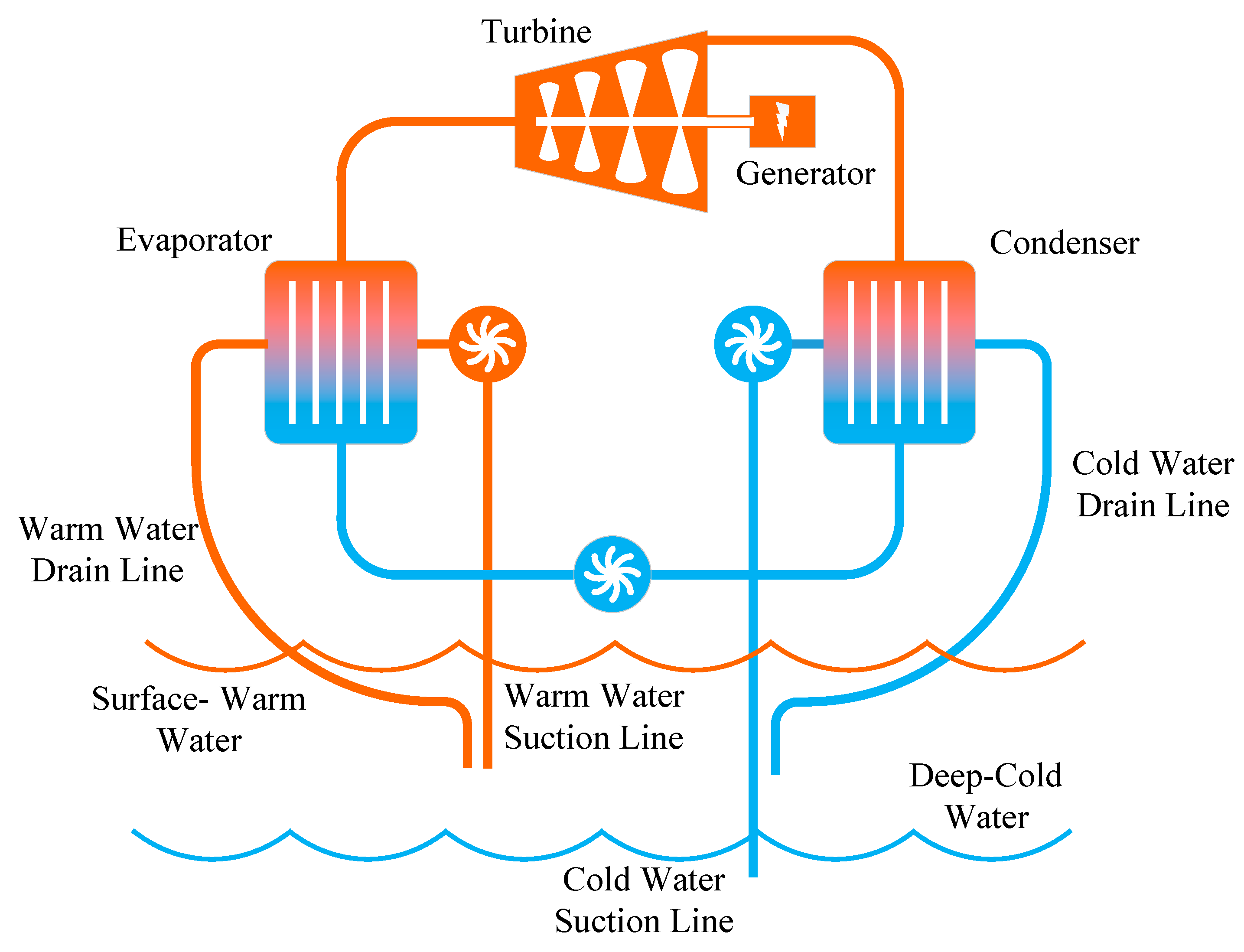
Figure 1: Schematic diagram of ocean thermal energy conversion principle [9].
The characteristic parameters and technical parameters, including length, wall thickness, material, and diameter of the cold-water pipe is crucial for Ocean Thermal Energy Conversion (OTEC), as only when the water intake depth reaches a certain value can it provide a sufficient temperature gradient [10]. Typically, for ocean thermal energy equipment with a capacity exceeding 100 MW, the diameter of the cold-water intake pipe is no less than 10 m, while the wall thickness of such a large-diameter pipe is only about 10–50 mm [11,12]. Additionally, to ensure the cold source temperature is sufficiently low, it is generally necessary to extract deep seawater from depths of approximately 800–1000 m [13,14]. Since the cold-water pipe is installed in a suspended manner on the OTEC platform, environmental factors such as wind, waves, currents, and platform movement in the marine environment can significantly impact the safety of the cold-water intake pipe. To ensure the operational safety of the cold-water intake pipe, it is necessary to analyze its mechanical behavior under marine environmental conditions to obtain reliable operational results.
In terms of the safety of cold-water pipes in OTEC systems, scholars domestically and internationally have conducted extensive research. For instance, studies have investigated the impact of variations in water transport flow rate on the structural integrity of pipe during commercial development, and the feasibility of applying glass fiber reinforced plastic (GFRP) cold water pipes in offshore environments was validated. This pipe was developed by modifying traditional land-based pipes, with an outer diameter of 4 m, and it was confirmed that it can be installed using marine ships [15]. Some scholars have focused on the mechanical performance of marine pipelines, studying free-spanning pipelines and risers, among other marine pipe structures. They conducted theoretical analyses and experimental tests on issues related to vibration and fracture, clarifying the influence mechanisms of internal/external flow-induced vibrations, microstructure, and fracture toughness. This work provides theoretical guidance for the application of such pipelines [16,17]. Regarding vortex-induced vibration in pipelines, scholars have considered factors such as current velocity and pipeline structure. They analyzed key parameters affecting vortex-induced vibration, including lift coefficient, drag coefficient, shedding frequency, and determined the characteristics of vibration changes through theoretical analysis [18,19]. In terms of fatigue performance, researchers have developed various fatigue damage evolution models and investigated the effects of factors such as corrosion pits and pre-stress on the fatigue behavior of pipelines [20,21].
In the analysis of the mechanical properties of OTEC CWP, research mainly focuses on the following aspects. Halkyard et al. [22] pointed out that the design of the cold-water pipe is a technical challenge in OTEC system design, and due to the large volume of seawater within the cold-water intake pipe, the dynamic coupling between the cold-water pipe and the platform is particularly important. To address this, they developed corresponding software systems for analyzing the coupled response of the cold-water pipe and the platform, while also verifying fluid flow within the pipe and local effects at the pipe-platform connection. Si et al. [23], without considering waves, currents, or platform motion, studied the impact of internal flow on the dynamic performance of the cold-water pipe. Their model was a cantilevered fluid-conveying pipe beam model, using the Galerkin method to discretize and solve the equations. They analyzed the effects of axial flow velocity ratio, flow angle ratio, and tangential flow velocity ratio on critical flow velocity, noting that the tangential flow velocity ratio is a prerequisite for correctly evaluating and accurately predicting critical flow velocity. Guan et al. [24], based on deepwater drilling conveyance pipes, analyzed various complex loads acting on the conveyance pipe in the marine environment. Using Euler-Bernoulli beam theory, they established a quasi-static load calculation model for deepwater conveyance pipe, studying the effects of marine environmental loads, platform offset, bottom counterweights, and other factors on the stress, deformation, and strength of the conveyance pipe, and proposed optimization solutions for the pipe structure. Zhang et al. [25], considering the marine environmental conditions of the pipe, applied the generalized integral transform method to solve the vibration equations of the Euler-Bernoulli beam model under multiple boundary conditions. They studied the time-effectiveness of the dynamic response of the pipe, analyzed natural frequencies and pipe amplitudes under different boundary conditions such as structural damping, internal flow velocity, external flow velocity, and counterweights, and proposed conditions for the occurrence of critical instability flow velocity. Hou et al. [26] established a fluid-structure interaction model combining the structural equations of the OTEC platform’s cold-water pipe and the wake oscillator equations, conducting a time-domain analysis. They studied the effects of external flow fields, internal flow fields, aspect ratio, and ballast mass on the vortex-induced vibrations of the cold-water pipe. Gu et al. [27] used the generalized integral transform to study the dynamic response of vortex-induced vibrations in long-distance flexible pipes. They established a time-varying second-order partial differential equation considering cross-flow forces and solved the model using the generalized integral transform and the DIVPAG method, concluding the effects of flexible pipe elongation on mean axial tensile stress and the impact of axial tension changes on vortex-induced vibrations. Rasgianti et al. [28] studied the bending effects of ocean currents on the cold-water pipe, validated its structure using numerical analysis methods, and identified an optimal simulation mesh size of 55 mm.
This paper addresses the stress issues in the cold-water intake pipe of offshore floating OTEC systems. Based on the Euler-Bernoulli beam model, a static load calculation method for the cold-water pipe is established. The lateral displacement of the pipe and surface stress under different marine environmental conditions are analyzed, providing a theoretical basis for the strength design of cold-water intake pipes in OTEC systems.
2 Mechanical Model of Cold-Water Intake Pipe
During the ocean thermal energy conversion sea trial, the cold-water intake pipe is deployed to a certain depth in the ocean via an engineering vessel. Deep cold seawater is extracted through a cold-water pump to serve the condensation and cooling process in the condenser. The entire cold water intake pipe is exposed to seawater, with its lower end connected to counterweight blocks. It is subjected to various forces, including the pipe’s gravity, buoyancy, wave forces, and ocean current forces. The physical model and force analysis are illustrated in Fig. 2 below. To establish the mechanical model of the cold-water intake pipe, the following assumptions are made:
- (1)The intake pipe is considered as a small-deflection beam undergoing combined axial-flexural deformation under transverse loading.
- (2)The influence of pipe joints is neglected, and the pipe remains in the elastic deformation stage with isotropic material properties.
- (3)Both the internal and external flows are homogeneous, with the internal flow being unidirectional and having constant velocity and seawater density.
- (4)The lift force from ocean currents and the heaving motion of the vessel are neglected. The wave force and ocean current force acting on the intake pipe are assumed to propagate in the same direction.
- (5)The virtual tension generated by the liquid level difference inside the pipe is neglected.
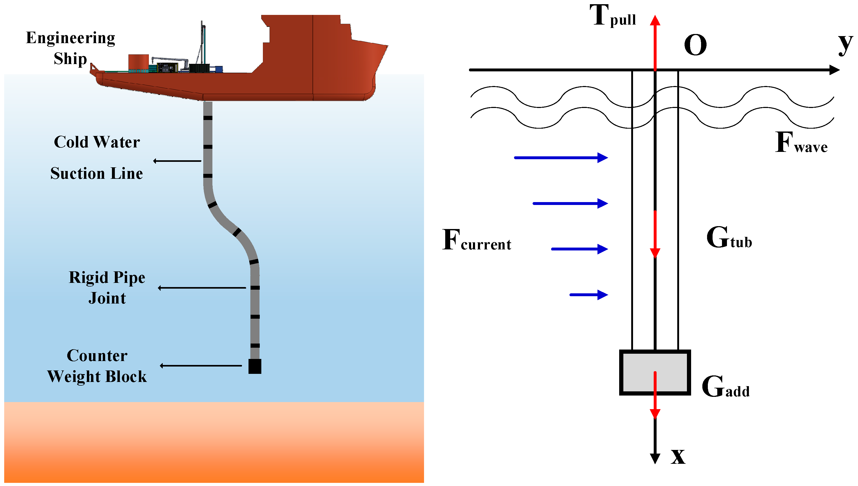
Figure 2: Physical model and force analysis of the free-standing cold water intake pipe column for OTEC.
The main nomenclature is determined in Table 1.
Table 1: Nomenclature.
| EI | Bending stiffness of the intake pipe | N·m2 |
| T(x) | Axial load distribution along the x-direction of the intake pipe | N |
| Gunit | Submerged weight per unit length of the intake pipe | N |
| F(x) | Transverse wave-current load distribution along the x-direction of the intake pipe in seawater | N |
| ω | Circular frequency of the cold-water pipe | rad |
| FD | Drag force generated by wave-current interaction | N |
| FI | Inertial force generated by wave-current interaction | N |
| Dr | Outer diameter of the intake pipe | m |
| ρ | Seawater density | kg/m3 |
| CD | Drag force coefficient, dimensionless | Dimensionless |
| vw | Horizontal velocity of water particles due to waves | m/s |
| vc | Velocity of water particles induced by ocean currents | m/s |
| Cm | Inertial force coefficient, dimensionless | Dimensionless |
| aw | Acceleration of water particles induced by waves | m/s2 |
| vm | Wind-induced current velocity at the sea surface | m/s |
| vt | Tidal current velocity at the sea surface | m/s |
| h | Water depth | m |
| H | Wave height | m |
| Tw | Wave period | s |
| k | Wave number, k = 2π/Lw | Dimensionless |
| ωw | Wave circular frequency | rad/s |
The small-deflection beam under combined axial-flexural deformation can be treated as an Euler-Bernoulli bending beam with a fixed top and free bottom. Using the top of the pipe as the coordinate origin, the direction of the ocean current as the y-axis, and the vertically downward direction of the pipe as the positive x-axis, the governing equation of the intake pipe can be expressed as:
During operation, the intake pipe is in a tension state. The effective axial load is given by:
In the transverse direction, the pipe is primarily subjected to the combined action of wave and current forces. When the diameter-to-length ratio of the pipe is less than 0.2, the presence of the pipe can be considered to have negligible influence on wave dynamics. Under such conditions, the Morison equation may be employed to represent the combined wave-current force per unit length acting on the water intake pipe, expressed as follows:
To calculate the effect of ocean current forces on the intake pipe, it is necessary to determine the variation of current velocity with water depth. In the absence of measured data, the formula recommended by the American Bureau of Shipping is adopted:
Linear wave theory is applied to compute the horizontal velocity and horizontal acceleration of water particles:
The finite difference method is employed to express the derivatives in the governing equation of the intake pipe using their difference quotient forms:
Substituting Eqs. (7)–(9) into (1) yields:
In the model, the boundary conditions are defined as follows: at the origin (top of the pipe), the displacement is 0 and the rotation angle is 0; at the bottom of the pipe, the bending moment is 0 and the shear force equals the combined wave-current force:
According to the theory of material mechanics, the rotation angle, bending moment, and shear force of a Euler-Bernoulli beam can be expressed as follows:
Substituting Eqs. (7)–(9) and Eqs. (15)–(17) into Eqs. (11)–(14), respectively, and simplifying, the boundary conditions of the discretized governing equations for the CWP are obtained as:
From the above Eqs. (18)–(21), four equations are derived. Combined with the n + 1 equations from Eq. (10), this gives a total of n + 5 equations. These n + 5 equations determine n + 5 unknowns, allowing the solution of the system to be determined. The matrix form of the above equations is as follows:
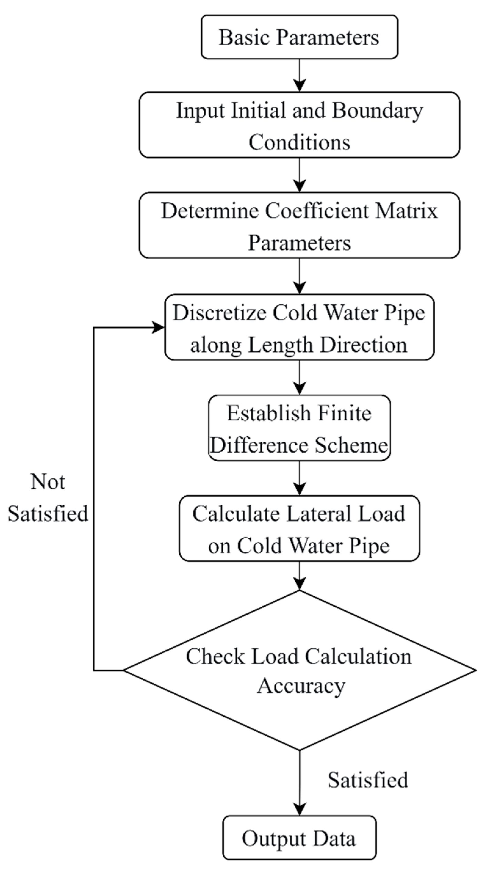
Figure 3: Flow chart of calculation process.
Taking China’s first Ocean Thermal Energy Conversion power generation project as an example. In 2023, China’s first 20 kW offshore floating ocean thermal energy conversion (OTEC) power generation system, deployed aboard the “Marine Geology No. 2” vessel, successfully completed sea trials in the South China Sea, as shown in Fig. 4. The system operated for a total duration of 4 h and 47 min, achieving a maximum power output of 16.4 kW with an effective power generation efficiency of 17.7%. These results validate the feasibility and practical applicability of the OTEC system’s working principle [29].
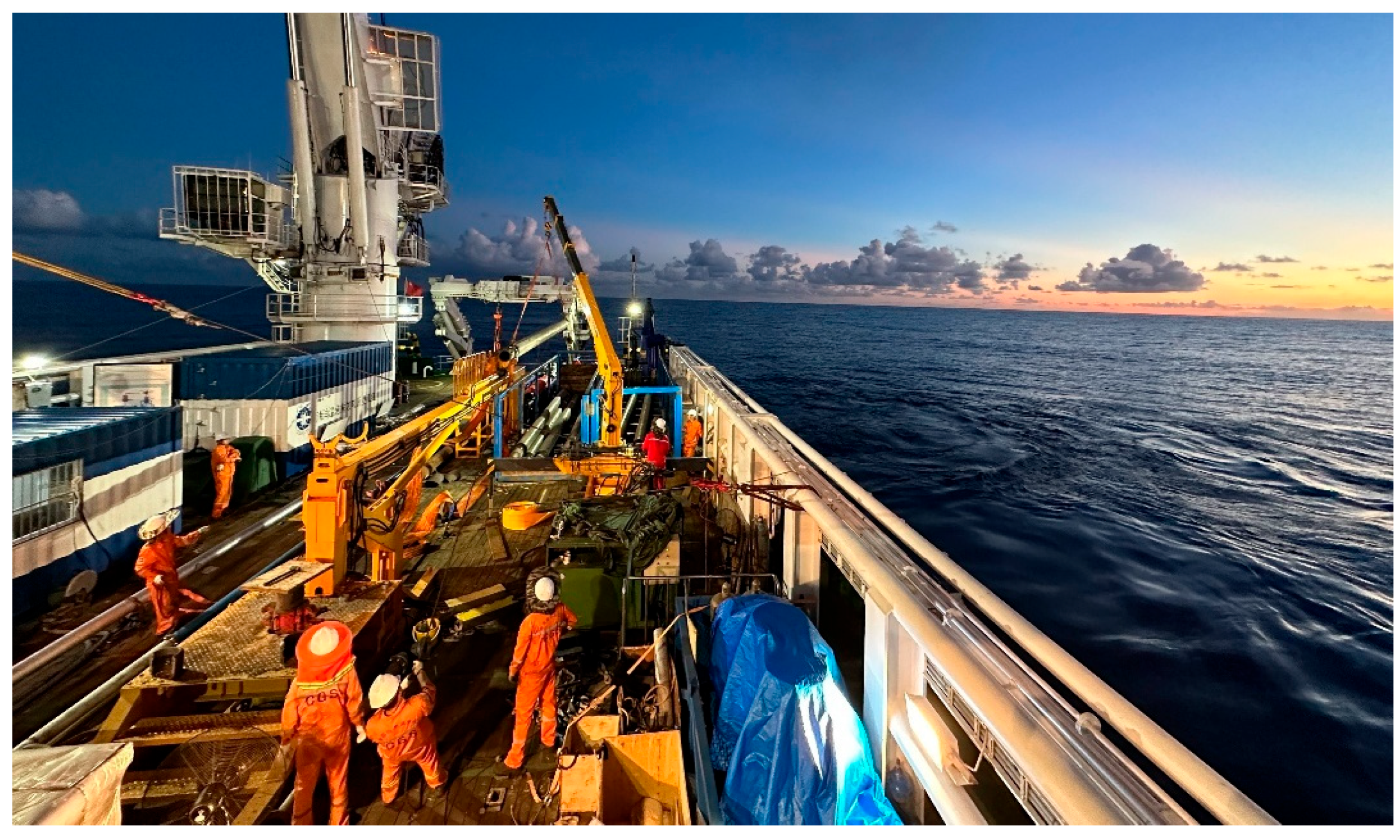
Figure 4: Sea trial operation site [29].
To validate the design rationale of the 244.5 mm CWP utilized in the 20 kW OTEC system and to provide theoretical support for subsequent CWP designs in OTEC systems, conduct a systematic analysis of the hydrodynamic forces acting on the CWP in its operational environment. Based on the mechanical model of the CWP, the investigation further examines the pipe’s displacement and surface bending moment under varying current and wind-induced flow velocities. The CWP calculation parameters seen in Table 2. The calculation results are as follows.
Table 2: Physical properties of CWP case.
| Parameters | Value |
|---|---|
| CWP length, m | 1000 |
| CWP outer diameter, mm | 244.5 |
| CWP wall thickness, mm | 11.99 |
| CWP modulus of elasticity, GPa | 210 |
| CWP Poisson’s ratio | 0.3 |
| CWP density, kg/m3 | 7850 |
| Bottom counterweight, t | 20 |
| Seawater density, kg/m3 | 1025 |
| Seawater drag coefficient | 1.2 |
| Inertial force coefficient [30] | 2.0 |
| Wave period, s | 8 |
| Wave height, m | 6.5 |
| Surface tidal current velocity, m/s | 2 |
| Surface wind-driven current velocity, m/s | 0.5 |
Fig. 5 and Fig. 6 illustrate the variations in water particle velocity and acceleration due to currents at a depth of 100 m below sea level. The figures indicate that at 50 m below the sea surface, the water particle velocity and acceleration change significantly. The water surface exhibits simple harmonic oscillations, vibrating with a fixed circular frequency, while the wave pattern propagates forward at a certain speed, with the wave midline coinciding with the still water level. Below 50 m depth, the particle velocity and acceleration are almost unaffected by the wave period, and the particle acceleration becomes zero.
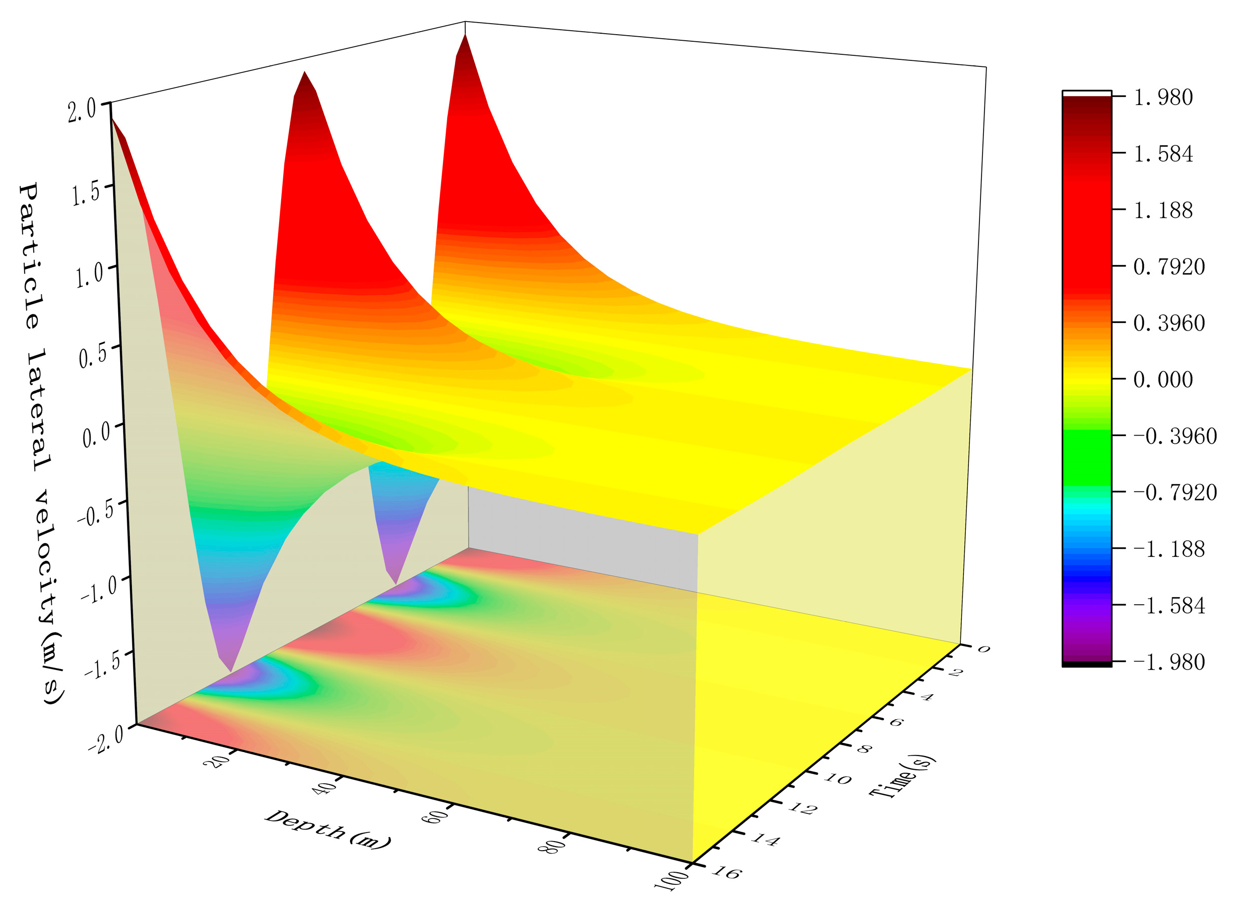
Figure 5: Water particle velocity from 0 to 100 m.
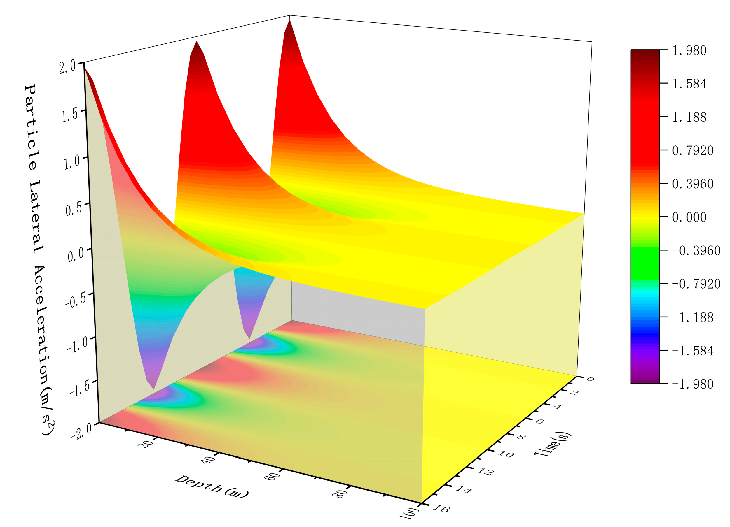
Figure 6: Water particle acceleration from 0 to 100 m.
Under the conditions of a wind-driven current velocity of 2 m/s and a tidal current velocity of 0.5 m/s, the wave loads at different depths up to 100 m below sea level are shown in Fig. 7. The figure shows that the wave loads at different depths exhibit sinusoidal fluctuations with a fixed circular frequency. Within one load cycle, the maximum value is 362 N. When the water depth exceeds 50 m, the wave load decreases sharply, and the influence of the wave period on the load also diminishes significantly, stabilizing at around 40 N.
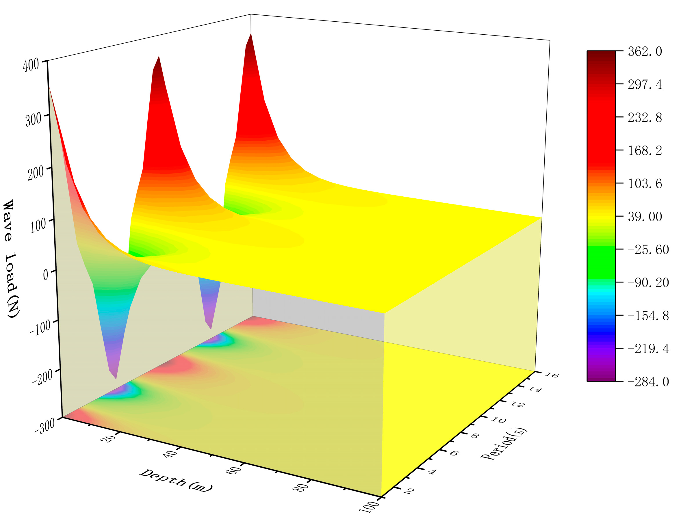
Figure 7: Wave load from 0 to 100 m.
Due to the limited effective depth of wave load influence, when the water depth exceeds 100 m, the wave load decreases linearly, dropping from 40 N at 100 m to 10 N, as shown in Fig. 8.
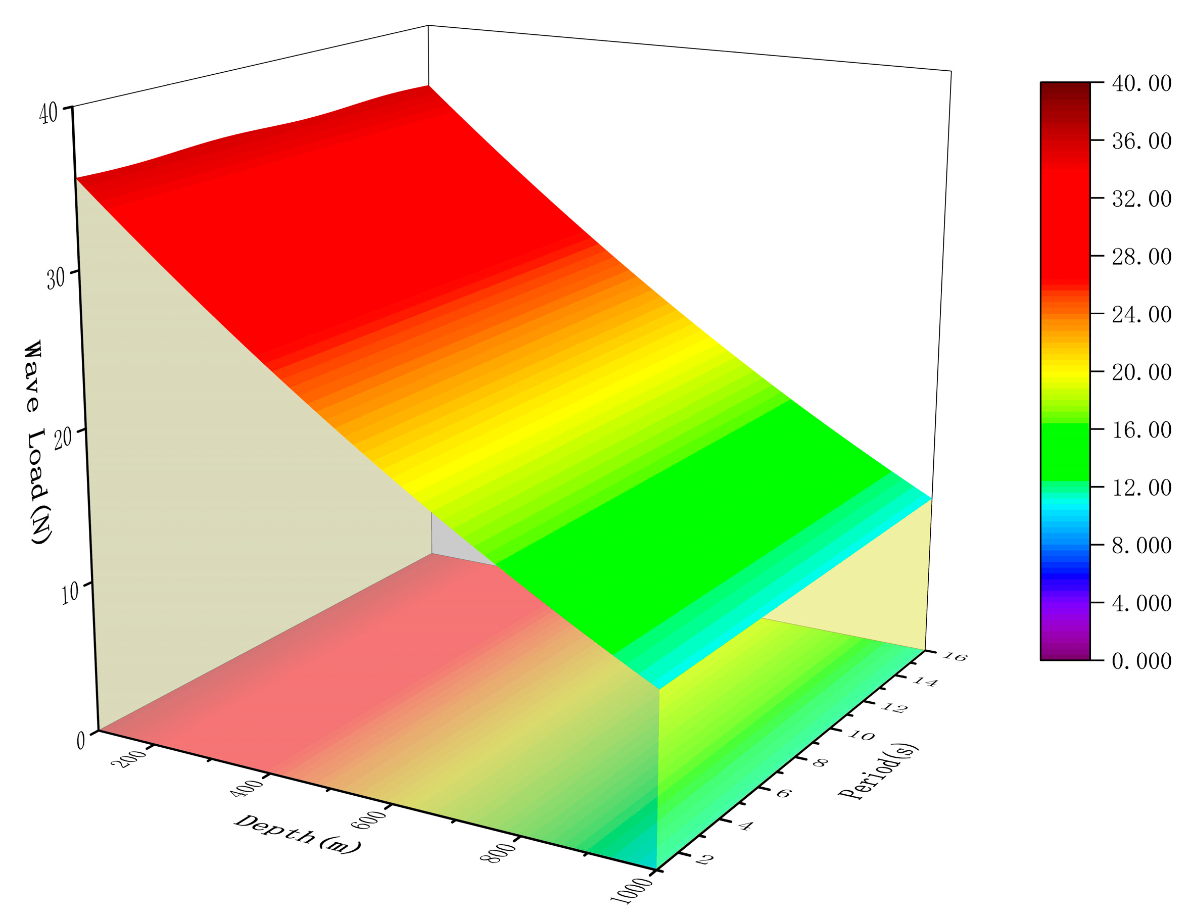
Figure 8: Wave load from 100 to 1000 m.
Fig. 9 below analyzes the lateral displacement of the intake pipe under a tidal current velocity of 0.5 m/s and wind-driven current velocities ranging from 0.5 to 3.0 m/s. When the tidal current velocity is fixed, the maximum lateral displacement of the pipe gradually increases as the wind-driven current velocity increases. When the wind-driven current velocity reaches 3.0 m/s, the maximum lateral displacement of the pipe reaches 17 m, occurring near the depth of 700–750 m. Below 700 m, the lateral displacement gradually decreases due to the restraining effect of the counterweight block, eventually stabilizing at approximately 16.5 m at the bottom of the pipe.
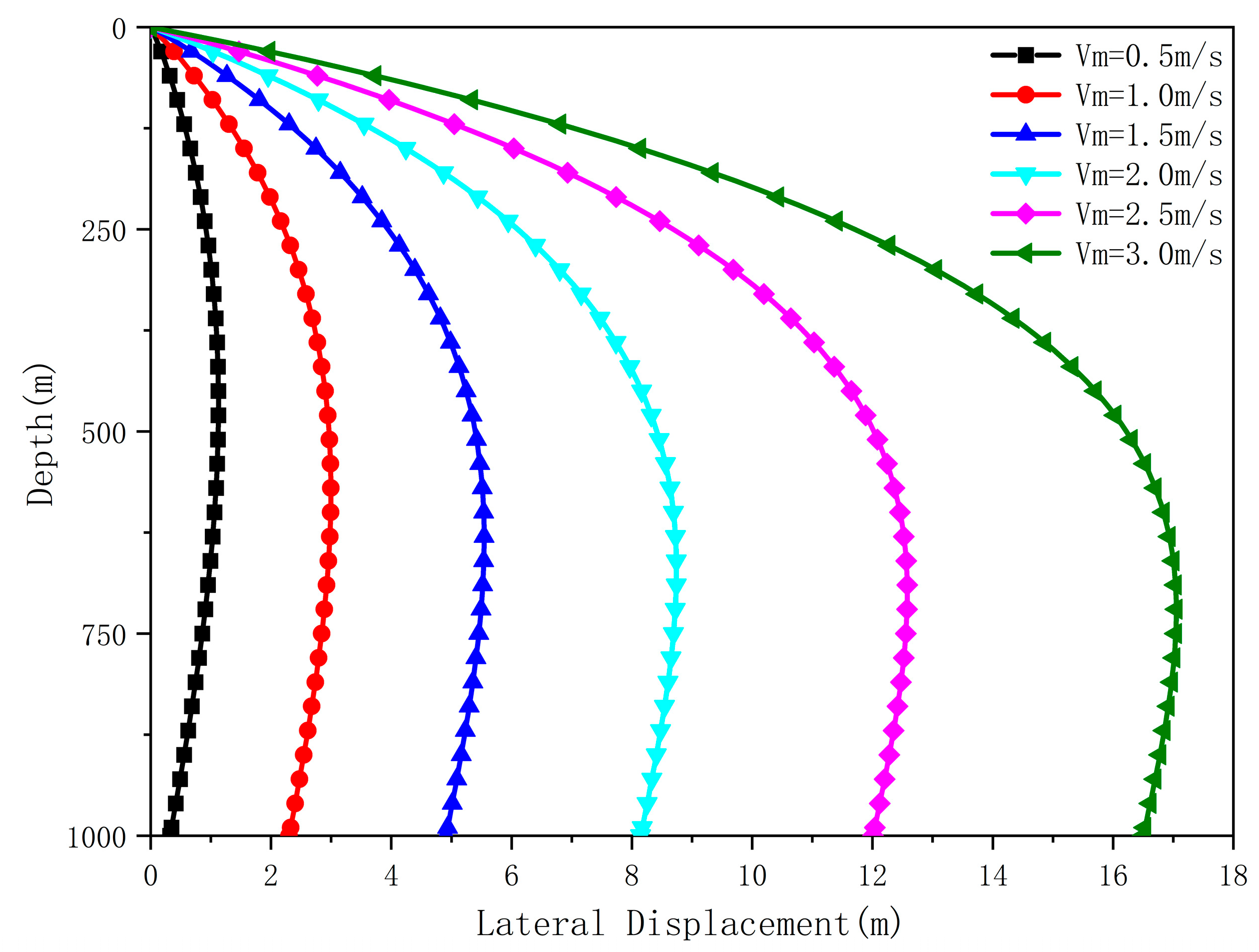
Figure 9: Lateral deformation of the intake pipe under different wind-driven current velocities.
Fig. 10 below analyzes the lateral displacement of the intake pipe under a wind-driven current velocity of 2 m/s and tidal current velocities ranging from 0.1 to 0.9 m/s. When the wind-driven current velocity is fixed, the maximum lateral displacement of the pipe gradually increases as the tidal current velocity increases. When the tidal current velocity reaches 0.9 m/s, the maximum lateral displacement of the pipe reaches 11.3 m, occurring near the depth of 580–630 m. Below 650 m, the lateral displacement gradually decreases due to the restraining effect of the counterweight block, eventually stabilizing at approximately 9.1 m at the bottom of the pipe.
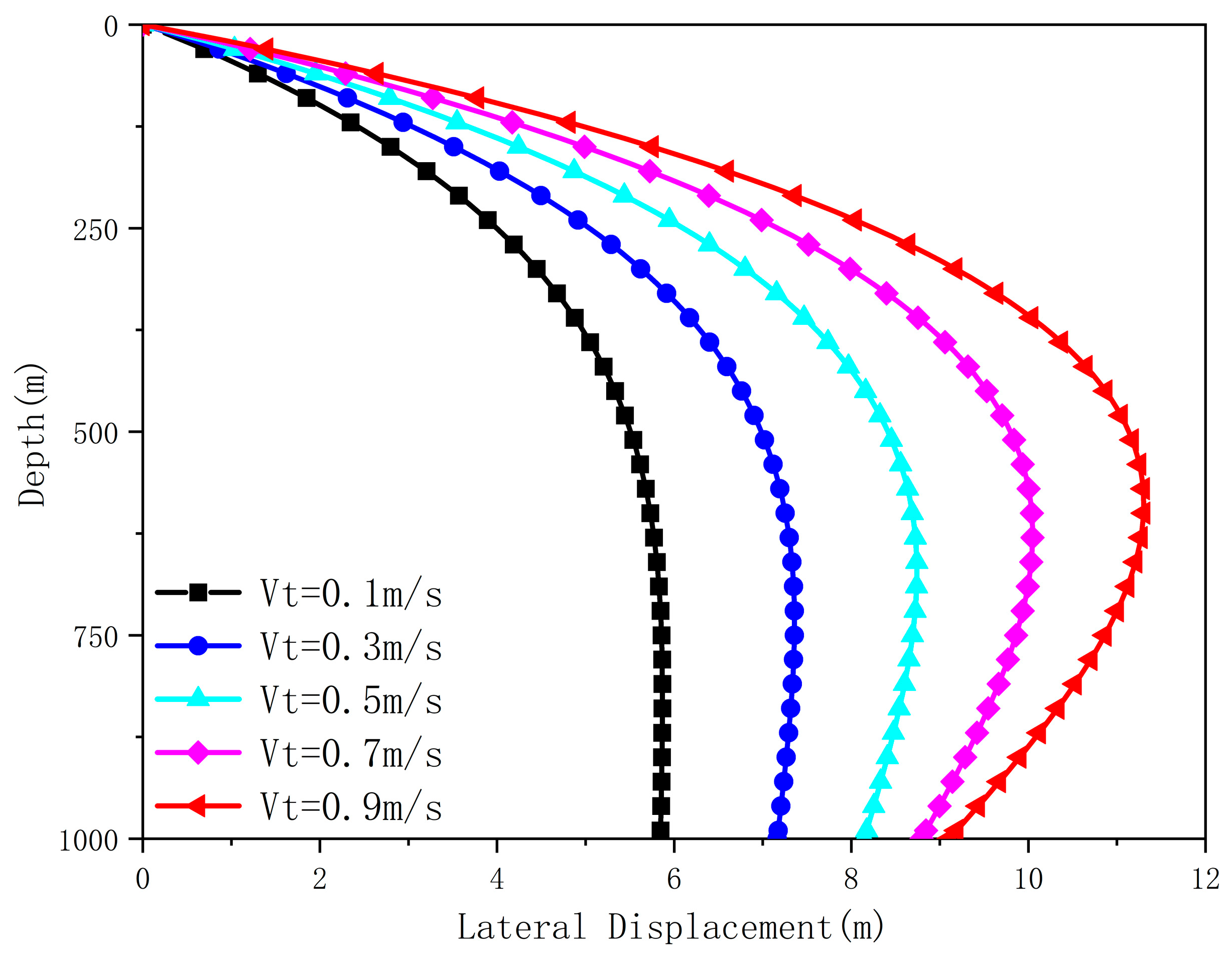
Figure 10: Lateral deformation of the intake pipe under different tidal current velocities.
3.3 Outer Surface Bending Moment of Pipe
Fig. 11 shows the surface stress distribution of the intake pipe under a wind-driven current velocity of 2 m/s and a tidal current velocity of 0.5 m/s. Given the minimal pressure difference between the inside and outside of the intake pipe, the influence of radial and hoop stresses on the total stress is neglected. The figure indicates that the maximum stress on the outer wall of the intake pipe occurs at the top. The total stress at the top, under the combined action of tensile and bending stresses, is 229 MPa. This suggests that using a pipe with greater wall thickness and higher strength at the top of the structure is beneficial for enhancing the structural safety of the intake pipe. As the water depth increases, the total stress on the outer wall gradually decreases. At the bottom where bending stress is relatively small, the stress is primarily influenced by the tensile stress from the lower counterweight block.
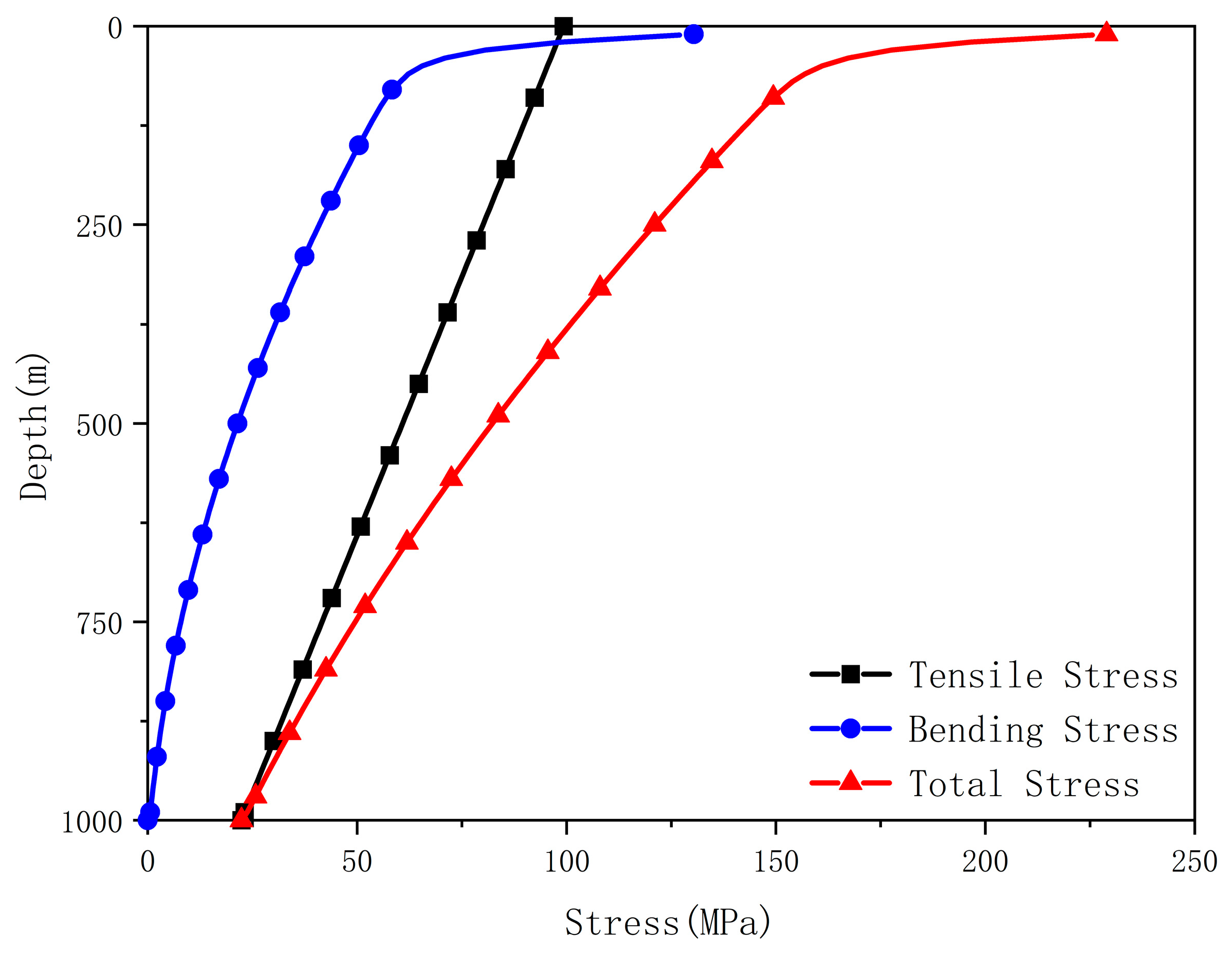
Figure 11: Surface stress of the intake pipe at different depths.
As evidenced by the aforementioned results, wave-induced loads are predominantly concentrated in the upper 100 m, exhibiting a gradual attenuation with increasing depth—decreasing from 40 N to 10 N. Therefore, during the CWP design phase, structural reinforcement in the upper section must be considered to prevent potential failure caused by these elevated loads.
The primary factors influencing external hydrodynamic loads are identified as wind-induced and tidal current velocities. Within one operational cycle, the maximum external load reaches 362 N. Under this load condition, the 1000-m CWP demonstrates significant lateral displacement within the 100–200 m depth interval. When subjected to a tidal current velocity of 0.5 m/s combined with a wind-driven current velocity of 3.0 m/s, the maximum displacement in the lower section can attain 17 m.
Further analysis of surface stress distribution reveals that the total stress exceeds 150 MPa in the upper 100-m segment. This stress level imposes stringent requirements on both the strength and bending resistance of the upper pipe section. Consequently, the structural design process should incorporate appropriate measures to enhance strength and increase wall thickness in this critical region, thereby improving the overall structural suitability of the CWP system.
This study investigates the displacement and surface stress of the OTEC CWP under varying load conditions, yielding the following conclusions:
- (1)This study comprehensively considers the influence of the marine environment on the OTEC cold water intake pipe. Based on linear wave theory, the flow velocity and acceleration of water particles under waves were analyzed, along with the wave loads at different depths. Using the Euler-Bernoulli beam model, a static load calculation method for the cold-water pipe was established, enabling a quantitative analysis of the lateral displacement and surface stress of the intake pipe.
- (2)At depths above 50 m below sea level, the velocity and acceleration of water particles induced by waves exhibit simple harmonic motion. The wave profile oscillates symmetrically about the still water level and propagates forward at a characteristic phase velocity. With increasing tidal and wind-driven current velocities, lateral deformation of the intake pipe progressively intensifies. Due to the influence of bottom weights, the maximum lateral displacement occurs at depths between 600 and 800 m below sea level.
- (3)The maximum surface stress on the CWP is observed within the upper 100-m segment, which also corresponds to the region of most significant lateral displacement. Consequently, during subsequent structural design phases of the CWP, particular attention should be paid to the mechanical behavior of this section. Appropriate measures including enhanced material strength and increased wall thickness are recommended to improve the pipe’s operational reliability and structural safety.
Acknowledgement:
Funding Statement: This research was funded by Nansha District Science and Technology Project (Grant Number. 2024ZD008), This research is also funded by China Geological Survey (Grant number: No. DD20230066, DD20242659).
Author Contributions: Study’s planning, ideas, Jing Li; informational and data analysis, Bo Ning, Bo Li; literature evaluation, Fenlan Ou, Xuemei Jin; writing—review and editing, Jing Li, Dezhi Qiu. All authors have read and agreed to the published version of the manuscript. All authors reviewed the results and approved the final version of the manuscript.
Availability of Data and Materials: The data that support the findings of this study are available from the corresponding author, upon reasonable request.
Ethics Approval: Not applicable.
Conflicts of Interest: The authors declare no conflicts of interest to report regarding the present study.
References
1. Thirugnana ST , Singh AKA , Rahimi NFBM , Langer J , Nakaoka T , Ikegami Y . OTEC: the promising renewable energy in Sabah, Malaysia. In: 2024 IEEE 12th Region 10 Humanitarian Technology Conference (R10-HTC); 2014 Oct 1–3; Kuala Lumpur, Malaysia. p. 1– 8. doi:10.1109/R10-HTC59322.2024.10778704. [Google Scholar] [CrossRef]
2. Chung YC , Wu CI . Enhancing ocean thermal energy conversion performance: optimized thermoelectric generator-integrated heat exchangers with longitudinal Vortex generators. Energies. 2024; 17( 2): 526. doi:10.3390/en17020526. [Google Scholar] [CrossRef]
3. Khan N , Kalair A , Abas N , Haider A . Review of ocean tidal, wave and thermal energy technologies. Renew Sustain Energy Rev. 2017; 72: 590– 604. doi:10.1016/j.rser.2017.01.079. [Google Scholar] [CrossRef]
4. Mao L , Wei C , Zeng S , Cai M . Heat transfer mechanism of cold-water pipe in ocean thermal energy conversion system. Energy. 2023; 269: 126857. doi:10.1016/j.energy.2023.126857. [Google Scholar] [CrossRef]
5. Kim HJ , Lee HS , Lim ST , Petterson M . The suitability of the Pacific Islands for harnessing ocean thermal energy and the feasibility of OTEC plants for onshore or offshore processing. Geosciences. 2021; 11( 10): 407. doi:10.3390/geosciences11100407. [Google Scholar] [CrossRef]
6. Liu WM , Liu L , Chen FY , Ma CL , Ge YZ , Peng JP . Technical progress of marine renewable energy in China. Sci Technol Rev. 2020; 38( 14): 27– 39. (In Chinese). [Google Scholar]
7. Saadha A , Ishihara KN , Ogawa T , Basu S , Okumura H . Techno-economic analysis of combined onshore ocean thermal energy conversion technology and seawater air conditioning in small island developing states. Sustainability. 2025; 17( 10): 4724. doi:10.3390/su17104724. [Google Scholar] [CrossRef]
8. Thirugnana ST , Jaafar AB , Rajoo S , Azmi AA , Karthikeyan HJ , Yasunaga T , et al. Performance analysis of a 10 MW ocean thermal energy conversion plant using Rankine cycle in Malaysia. Sustainability. 2023; 15( 4): 3777. doi:10.3390/su15043777. [Google Scholar] [CrossRef]
9. Zhang Y , Zheng M , Zhang L , Zhang C , Tan J , Zhang Y , et al. Investigation of dynamic behavior of ultra-large cold-water pipes for ocean thermal energy conversion. Dynamics. 2023; 3( 3): 468– 88. doi:10.3390/dynamics3030025. [Google Scholar] [CrossRef]
10. Giordani HD , Lages M , Medina M , Tan-Holmes J . Affects of the cold water pipe depth in ocean thermal energy converter plants with respect to power generation efficiency. PAM Rev Energy Sci Technol. 2015; 2: 50– 66. doi:10.5130/pamr.v2i0.1395. [Google Scholar] [CrossRef]
11. Adie PW , Adiputra R , Prabowo AR , Erwandi E , Muttaqie T , Muhayat N , et al. Assessment of the OTEC cold water pipe design under bending loading: a benchmarking and parametric study using finite element approach. J Mech Behav Mater. 2023; 32: 20220298. doi:10.1515/jmbm-2022-0298. [Google Scholar] [CrossRef]
12. Adiputra R , Utsunomiya T . Stability based approach to design cold-water pipe (CWP) for ocean thermal energy conversion (OTEC). Appl Ocean Res. 2019; 92: 101921. doi:10.1016/j.apor.2019.101921. [Google Scholar] [CrossRef]
13. Adie PW , Prabowo AR , Muttaqie T , Adiputra R , Muhayat N , Carvalho H , et al. Non-linear assessment of cold water pipe (CWP) on the ocean thermal energy conversion (OTEC) installation under bending load. Procedia Struct Integr. 2023; 47: 142– 9. doi:10.1016/j.prostr.2023.07.005. [Google Scholar] [CrossRef]
14. Adiputra R , Utsunomiya T , Koto J , Yasunaga T , Ikegami Y . Preliminary design of a 100MW-net ocean thermal energy conversion (OTEC) power plant study case: mentawai island, Indonesia. J Mar Sci Technol. 2020; 25( 1): 48– 68. doi:10.1007/s00773-019-00630-7. [Google Scholar] [CrossRef]
15. Xiang S , Cao P , Erwin R , Kibbee S . OTEC cold water pipe global dynamic design for ship-shaped vessels. In: Proceedings of the ASME 2013 32nd International Conference on Ocean, Offshore and Arctic Engineering; 2013 Jun 9–14; Nantes, France. p. V008T09A060. doi:10.1115/omae2013-10927. [Google Scholar] [CrossRef]
16. Li T , An C , Liang W , Duan M , Estefen SF . Semi-analytical solution for soil-constrained vibration of subsea free-spanning pipelines. Ships Offshore Struct. 2018; 13( 6): 666– 76. doi:10.1080/17445302.2018.1460090. [Google Scholar] [CrossRef]
17. Cao Y , Yin S , Li B , Jia S , Li Y , Qin Y , et al. Study on the mechanism between weld microstructure and crack Tie opening displacement fracture toughness of the steel catenary riser. Materials. 2025; 18( 1): 176. doi:10.3390/ma18010176. [Google Scholar] [CrossRef]
18. Krishnakumari A , Saravanan M , Vishal S , Amal Krishna A , Sharavana Kumar A , Lindsay SRK . Modelling and analysis of Vortex induced vibration in marine risers. Mater Today Proc. 2023. doi:10.1016/j.matpr.2023.02.324. [Google Scholar] [CrossRef]
19. Han J , Wang Z . Analysis of vibration characteristics of deep-sea mining risers under emergency disconnection state. Appl Ocean Res. 2025; 158: 104548. doi:10.1016/j.apor.2025.104548. [Google Scholar] [CrossRef]
20. Yin Z , Li Z , Zhou L , Wang Y , Huang X . A frequency-dependent high-cycle fatigue damage model and its application in crack nucleation of marine riser from corrosion pits. Fatigue Fract Eng Mat Struct. 2023; 46( 4): 1488– 99. doi:10.1111/ffe.13943. [Google Scholar] [CrossRef]
21. Sheehan JM , Grealish FW , Harte AM , Smith RJ . Characterizing the wave environment in the fatigue analysis of flexible risers. J Offshore Mech Arct Eng. 2006; 128( 2): 108– 18. doi:10.1115/1.2185129. [Google Scholar] [CrossRef]
22. Halkyard J , Sheikh R , Marinho T , Shi S , Ascari M . Current developments in the validation of numerical methods for predicting the responses of an ocean thermal energy conversion (OTEC) system cold water pipe. In: Proceedings of the ASME 2014 33rd International Conference on Ocean, Offshore and Arctic Engineering; 2014 Jun 8–13; San Francisco, CA, USA. p. V007T12A028. doi:10.1115/omae2014-24636. [Google Scholar] [CrossRef]
23. Si DY , Lv HN , Chen G , Xiao LF . Dynamics of cold water pipe in ocean thermal energy conversion. Ocean Eng. 2019; 37( 3): 120– 7. (In Chinese). doi:10.16483/j.issn.1005-9865.2019.03.014. [Google Scholar] [CrossRef]
24. Guan ZC , Li JJ , Han C , Zhang B , Zhao XF , Teng XQ , et al. Loads calculation and strength analysis of landing string during deepwater drilling. J China Univ Petrol Ed Nat Sci. 2018; 42( 2): 71– 8. (In Chinese). [Google Scholar]
25. Zhang L , Tan J , Zhang YL , Xu J , Huang SM , Duan QF , et al. Dynamics response analysis of a cold-water pipe for ocean thermal energy conversion under different boundary conditions. J Vib Shock. 2023; 42( 12): 59– 68. (In Chinese). doi:10.13465/j.cnki.jvs.2023.012.007. [Google Scholar] [CrossRef]
26. Hou ZH , Zheng ZQ , Chang ZY . Vortex-induced vibration performance of OTEC cold water pipe. China Offshore Platf. 2023; 38( 3): 1– 29. (In Chinese). [Google Scholar]
27. Gu JJ , An C , Carlos L , Su J . Prediction of Vortex-induced vibration of long flexible cylinders modeled by a coupled nonlinear oscillator: integral transform solution. J Hydrodyn. 2012; 24( 6): 888– 98. [Google Scholar]
28. Rasgianti , Adiputra R , Nugraha AD , Firdaus N , Sitanggang RB , Puryantini N , et al. Design optimization of stiffening system for ocean thermal energy conversion (OTEC) cold water pipe (CWP). Results Eng. 2024; 23: 102863. doi:10.1016/j.rineng.2024.102863. [Google Scholar] [CrossRef]
29. Successful Sea Trials of China’s First 20kW Floating OTEC Power Generation System [Internet]. [cited 2025 Dec 1]. Available from: http://gd.people.com.cn/n2/2023/0911/c123932-40566450.html. [Google Scholar]
30. Liu GJ , Wang QY , Tian XJ , Xie YC . Recent research and progress on hydrodynamic coefficients of marine structures with small scale pile. Period Ocean Univ China. 2020; 50( 1): 136– 44. (In Chinese). doi:10.16441/j.cnki.hdxb.20170255. [Google Scholar] [CrossRef]
Cite This Article
 Copyright © 2026 The Author(s). Published by Tech Science Press.
This work is licensed under a Creative Commons Attribution 4.0 International License , which permits unrestricted use, distribution, and reproduction in any medium, provided the original work is properly cited.
 Downloads
 Citation Tools