
 Submit a Paper
 Propose a Special lssue
 Open Access
ARTICLE
Gaussian Process Regression-Based Optimization of Fan-Shaped Film Cooling Holes on Concave Walls
1 College of Mechanical and Electrical Engineering, Taizhou University, Taizhou, 225300, China
2 College of Mechanical Engineering, Inner Mongolia University of Technology, Hohhot, 010051, China
3 College of Energy Science and Engineering, Harbin Institute of Technology, Harbin, 150001, China
* Corresponding Author: Zhiying Deng. Email:
Fluid Dynamics & Materials Processing 2026, 22(1), 9 https://doi.org/10.32604/fdmp.2026.074345
Received 09 October 2025; Accepted 23 December 2025; Issue published 06 February 2026
 View Full Text
 Download PDF
Abstract
In this study, a Gaussian Process Regression (GPR) surrogate model coupled with a Bayesian optimization algorithm was employed for the single-objective design optimization of fan-shaped film cooling holes on a concave wall. Fan-shaped holes, commonly used in gas turbines and aerospace applications, flare toward the exit to form a protective cooling film over hot surfaces, enhancing thermal protection compared to cylindrical holes. An initial hole configuration was used to improve adiabatic cooling efficiency. Design variables included the hole injection angle, forward expansion angle, lateral expansion angle, and aperture ratio, while the objective function was the average adiabatic cooling efficiency of the concave wall surface. Optimization was performed at two representative blowing ratios, M = 1.0 and M = 1.5, using the GPR-based surrogate model to accelerate exploration, with the Bayesian algorithm identifying optimal configurations. Results indicate that the optimized fan-shaped holes increased cooling efficiency by 15.2% and 12.3% at low and high blowing ratios, respectively. Analysis of flow and thermal fields further revealed how the optimized geometry influenced coolant distribution and heat transfer, providing insight into the mechanisms driving the improved cooling performance.Keywords
Since 1980, the reflux combustion chamber has evolved as one of the most common structural forms in small aero-engine combustion chambers [1]. Its comparative advantage lies in its unique airflow steering design that significantly reduces the length of the aero-engine’s shaft system. As a result, utilization efficiency can be improved. At the same time, the long flow path design inside its flame tube helps to achieve efficient combustion and a high-quality exit temperature field. However, this design poses severe challenges [2], in terms of cooling the flame tube wall. The unique concave wall structure of the flame tube in the reflux combustion chamber is also negatively affected by the high-temperature gas, which results in a large temperature gradient in the bending section of the concave wall tube. Due to the material’s limited high-temperature resistance, the concave wall tube is also prone to deformation and cracking. The latter effect can yield a significant reduction in the service life of the flame tube in the reflux combustion chamber. To meet the increasingly stringent requirements for thermal protection of hot components, improving the cooling efficiency [3] of hot components has become the primary research objective.
The most widely used external cooling technology is the air film cooling technology [4,5]. Film cooling can be described as an advanced cooling technology employed in both the industrial and aerospace sectors. It is commonly used for thermal management in high-temperature operating environments, such as turbines [6], workpiece processing, and rocket propulsion systems [7]. Film cooling holes are a vital component in film cooling technology; they are pore-like structures that open on the surface of high-temperature sections of gas turbines [8]. The geometry of the gas film holes determines the flow characteristics of the cooling jet [9], such as the velocity distribution and flow field structure, which affect the formation and coverage effect of the cold gas film. Therefore, when designing and optimizing a film cooling system, the geometry of the film cooling holes needs to be precisely controlled to achieve the best cooling effect.
The earliest shapes of air film holes were circular. The shape of the air film holes evolved as technology progressed and the need for cooling efficiency progressively increased. In the 1970s, Goldstein et al. [10] first demonstrated and quantified that fan-shaped holes produced better film cooling performance than cylindrical holes. With the emergence of fan-shaped holes, a variety of film cooling holes with different shapes has continuously appeared, such as CONSOLE studied by Yu et al. [11], the B-shaped and C-shaped holes studied by Luo et al. [12], Baseline Shaped studied by Schroeder et al. [13], and serrated trenched-hole studied by Huang et al. [14], spiral-channel hole Jia et al. [15]. Among these, the fan-shaped hole is one of the most commonly used shapes for holes. Compared with the conventional holes, the design of the fan-shaped hole weakens the shear mixing between the coolant jet and the mainstream. As a result, the ability of the jet to penetrate the mainstream is increased. However, the lateral width of the jet is increased. Numerous experimental and numerical studies have been also conducted to thoroughly examine the impact of hole geometry on cooling performance and the characteristics of the fan-shaped air film. For example, Seo et al. [16] optimized the fan-shaped air film holes for a lateral expansion angle of 10°. In another interesting work, Baek et al. [17] simulated fan-shaped air film holes for forward expansion angles ranging from 0° to 30°. In parallel, Fraas et al. [18] experimentally investigated the inlet geometries of fan-shaped film cooling holes. The impact of pore aspect ratio on-air film cooling performance was investigated using cylindrical holes by Johnson et al. [19] The complexity of the cooling system is also affected by the anisotropic air-film holes of several parameters. Any changes in a single parameter (e.g., forward inclination, lateral inclination, and aperture ratio) make it difficult to optimize the system’s cooling performance in a well-integrated manner.
To maximize the potential of the current cooling structure and achieve multi-parameter optimization of hole geometry, it is crucial to develop a scientific optimization strategy in conjunction with conducting algorithmic optimization. To this end, Liu et al. [20] performed a single-objective optimization of a fan-shaped air-film hole with a sizeable transversal space. In particular, the authors constructed a Kriging model instead of a physical model, and used a multi-island optimization algorithm to obtain the optimized solution. The optimized solution was obtained, and the space-averaged film cooling efficiency was defined as the objective function. Huang et al. [21] describes a multi-objective optimization method for round-to-slot shaped film-holes (RTSH) using computational fluid dynamic analysis and surrogate model approximation. Moreover, multi-island genetic algorithms and a non-dominated sequencing-based response surface approximation genetic algorithm (NSGA-II) were employed.
Therefore, fan-shaped holes provide excellent cooling effects, which can be improved by optimizing different parameters of the fan-shaped film cooling hole to enhance adiabatic cooling efficiency. Along these lines, in this work, different parameter modelling, meshing, and CFD numerical calculations were initially carried out. Then, a single-objective optimization design was carried out to enhance the adiabatic cooling efficiency of the concave wall film cooling holes with an initial film cooling hole. For the given spatial optimization problem, the Gaussian process regression surrogate model and Bayesian optimization algorithm were used to solve the optimal fan-shaped film cooling hole geometry parametrically.
2 Optimised Design and CFD Simulation
2.1 Geometric Model and Boundary Conditions
Fig. 1 shows the physical model and computational domain boundary conditions for the concave wall with an initial film cooling. The physical model applied in this work resembles that of a concave wall with an initial film cooling hole. More specifically, it consists mainly of a main flow channel, a secondary flow channel, 16 fan-shaped film cooling holes, and a conical initial film cooling hole. The diameter (D) of the air film hole was 1 mm, the extent of the main airflow channel was 120D and the height was 40D. The inlet of the secondary airflow channel had an extent and width of 40D and 8D, respectively, and the diameter of the concave wall was 76D, s is the concave wall archway length. The origin of the coordinate system was located at the upper right corner of the main flow channel inlet. The top-right portion of Fig. 1 depicts a magnified view of the initial film cooling hole, which consisted of a conical-shaped hole and a deflector sheet. The cold air flows through the initial film cooling hole and then flows into the fluid domain of the concave wall along the deflector sheet. The deflector sheet makes the cold air flow better adhered to the wall surface of the concave wall.
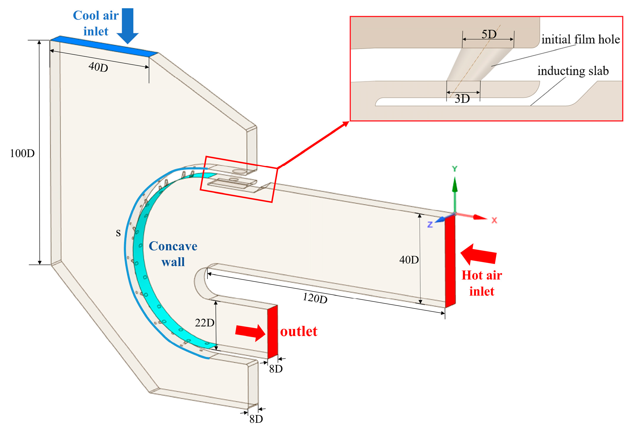
Figure 1: Diagram illustrating air film cooling on the concave wall.
The hot gas flow enters the main airflow channel from the right inlet, flows through the concave wall fluid domain, and exits from the main flow channel outlet. The fluid domain’s boundary conditions are detailed in Table 1. The mainstream inlet was set as a velocity inlet with a speed of 20 m/s, the airflow temperature at the inlet was set as 600 K, and the turbulence degree was 10%. The secondary airflow channel inlet was set as the velocity inlet, and the inlet velocity depends on different blowing ratios; the blowing ratios were M = 1 and M = 1.5, respectively, defined in Eq. (1).
The temperature of the inlet airflow to the secondary flow channel was set at 300 K with turbulence of 10%. The wall surface was set to be non-slip. The gas flow was considered an ideal gas flow. The thermal conductivity and the viscosity coefficient were calculated using kinetic theory and Sutherland’s law, respectively. The outlet was set as a pressure outlet, and the static pressure was defined as 300 kPa. Furthermore, the sides of the fluid domain were defined as periodic surfaces. All other wall surfaces were set as walls, adiabatic, and slip-free. The specific boundary conditions are listed in Table 1.
Table 1: Fluid domain boundary conditions.
| Main Flow | Secondary Flow | Outlet | ||
|---|---|---|---|---|
| 600 | 20 | 300 | M = 1.0, 1.5 | 300 |
In this work, numerical simulations were carried out using the separation implicit solver of the software ANSYS Fluent for the steady-state solution, to ensure the reliability of numerical simulations, the computational method was validated using a cylindrical hole in a flat plate model, The specific computational model and boundary conditions are detailed in the Reference [22]. Fig. 2a compares experimental data from Sinha [23] with CFD results. The turbulence model was selected through comparative analysis of different turbulence models. Fig. 2b presents the comparison of cooling efficiency on concave wall surfaces under various turbulence models, with the Realizable k-ε turbulence model [24,25] ultimately adopted. The pressure field was solved using the SIMPLEC algorithm for pressure-velocity coupled solution, the discrete equations were calculated using the second-order windward differential format, and the relative residuals in the computational process were less than 10−6. The outlet’s temperature and mass flow rate were monitored. Once these parameters stabilize, the calculation is considered converged, which indicates the end of the simulation calculation.
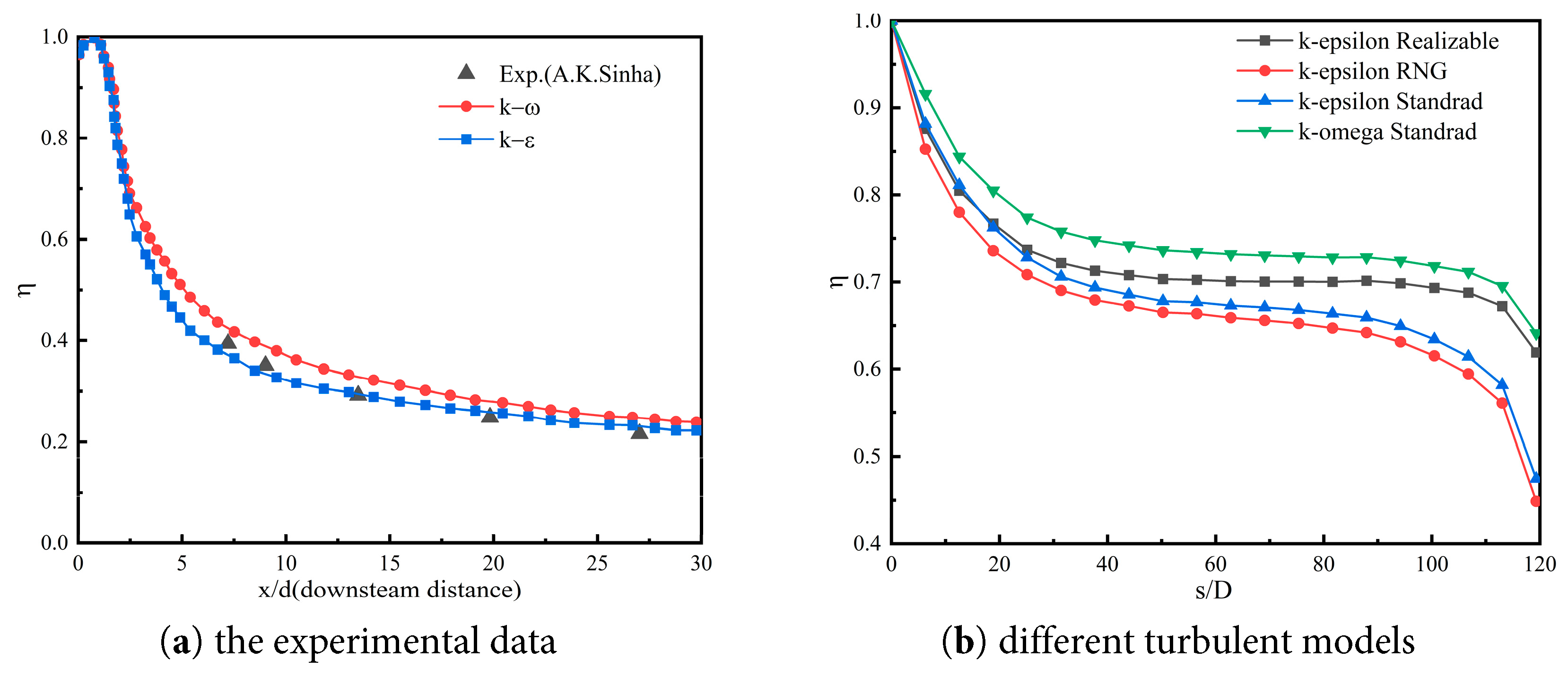
Figure 2: Validation of models.
Fig. 3 displays the body mesh generated by the numerical model; the mesh of the whole computational domain in the figure was unstructured, and the unstructured mesh was generated by the commercial computational fluid dynamics software Ansys Fluent Meshing. To improve the computational accuracy and save computational costs, a mixture of polyhedral and hexahedral methods were used to generate the meshes in the software. Considering that the middle part of the main airflow channel and the secondary airflow channel have a single structure and a simple flow field, no mesh refinement was required. As a result, polyhedral meshes were generated for this part. However, the part near the wall of the main airflow channel and the secondary airflow channel had a complex structure and variable flow field, which required mesh refinement. For this reason, a hexahedral mesh was generated for this part. In addition, Local encryption was also implemented for each film cooling hole, including the initial film cooling hole, as illustrated in Fig. 4. To avoid the effect of sensitivity of the number of meshes in the fluid domain and find out the optimum number of computational meshes, five sets of data were obtained for comparison by varying the mesh density of the fan holes and the initial film cooling hole. By comparing the average adiabatic film cooling efficiency under different mesh quantities, it was found that increasing the mesh count from 500,000 to 4,000,000 has a negligible impact on the cooling efficiency of the concave wall. Therefore, in the subsequent numerical simulations, the number of grids was chosen to be around 2 million. A comparison of the changes in the surface temperature of the concave wall with different numbers of grids is shown in Fig. 5.
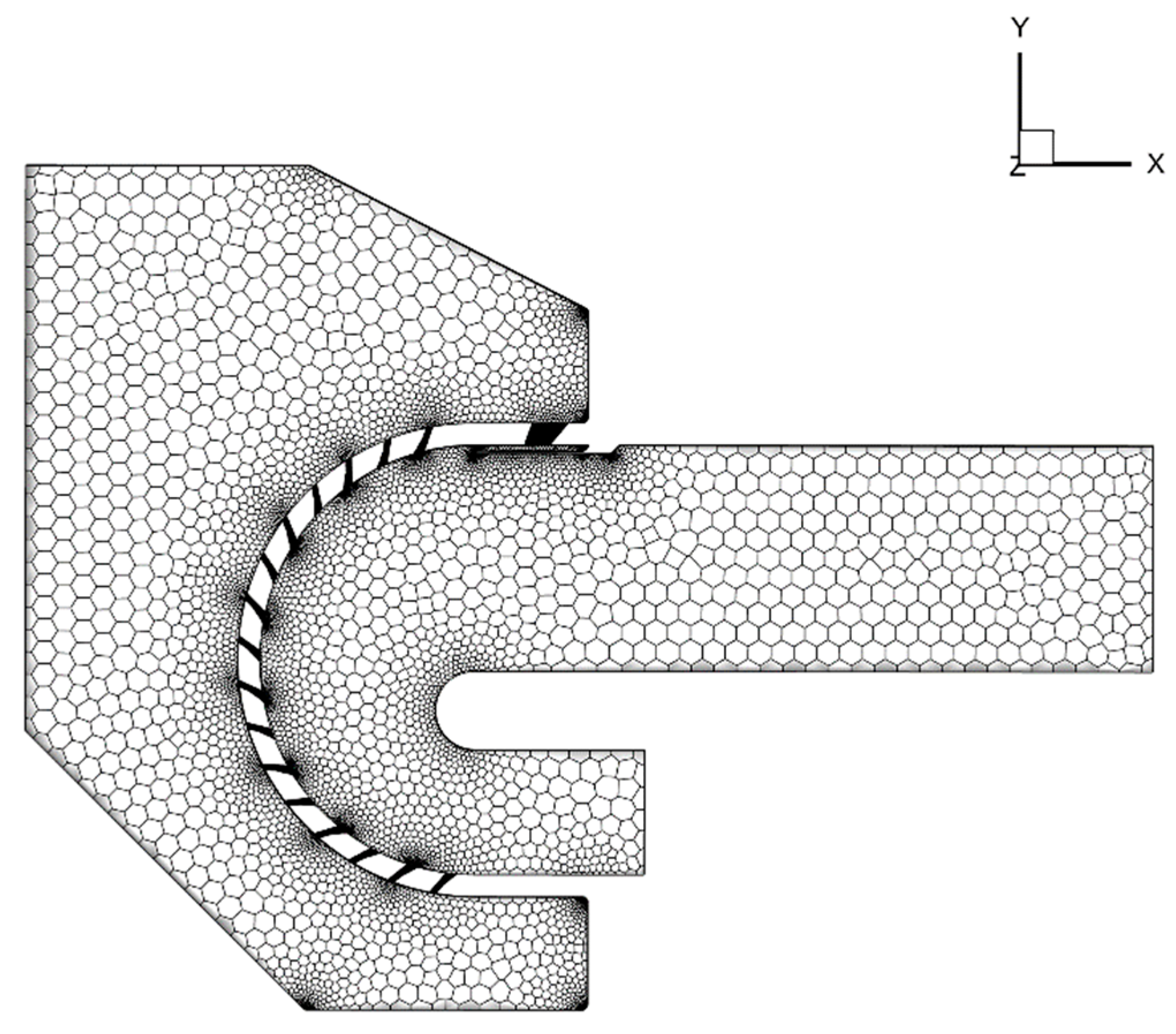
Figure 3: Example of the numerical model grid.
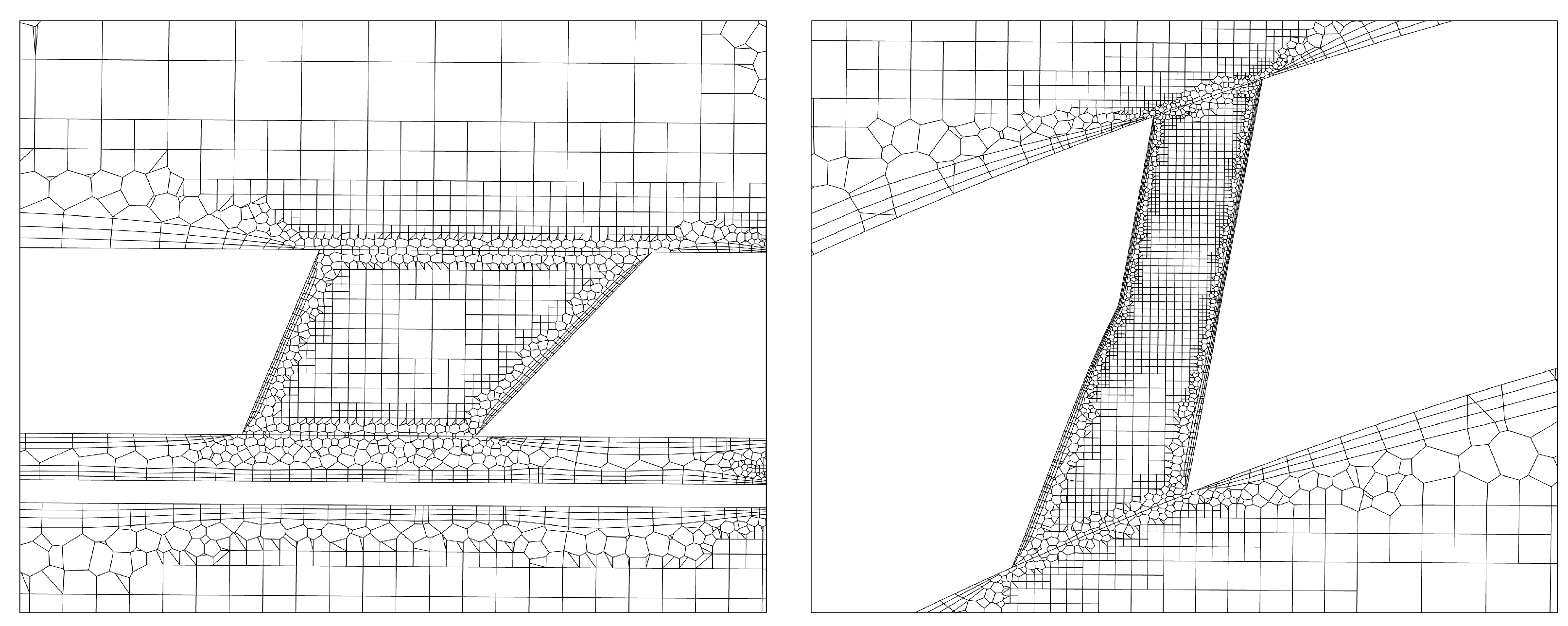
Figure 4: Example of an enlarged grid of film cooling holes.
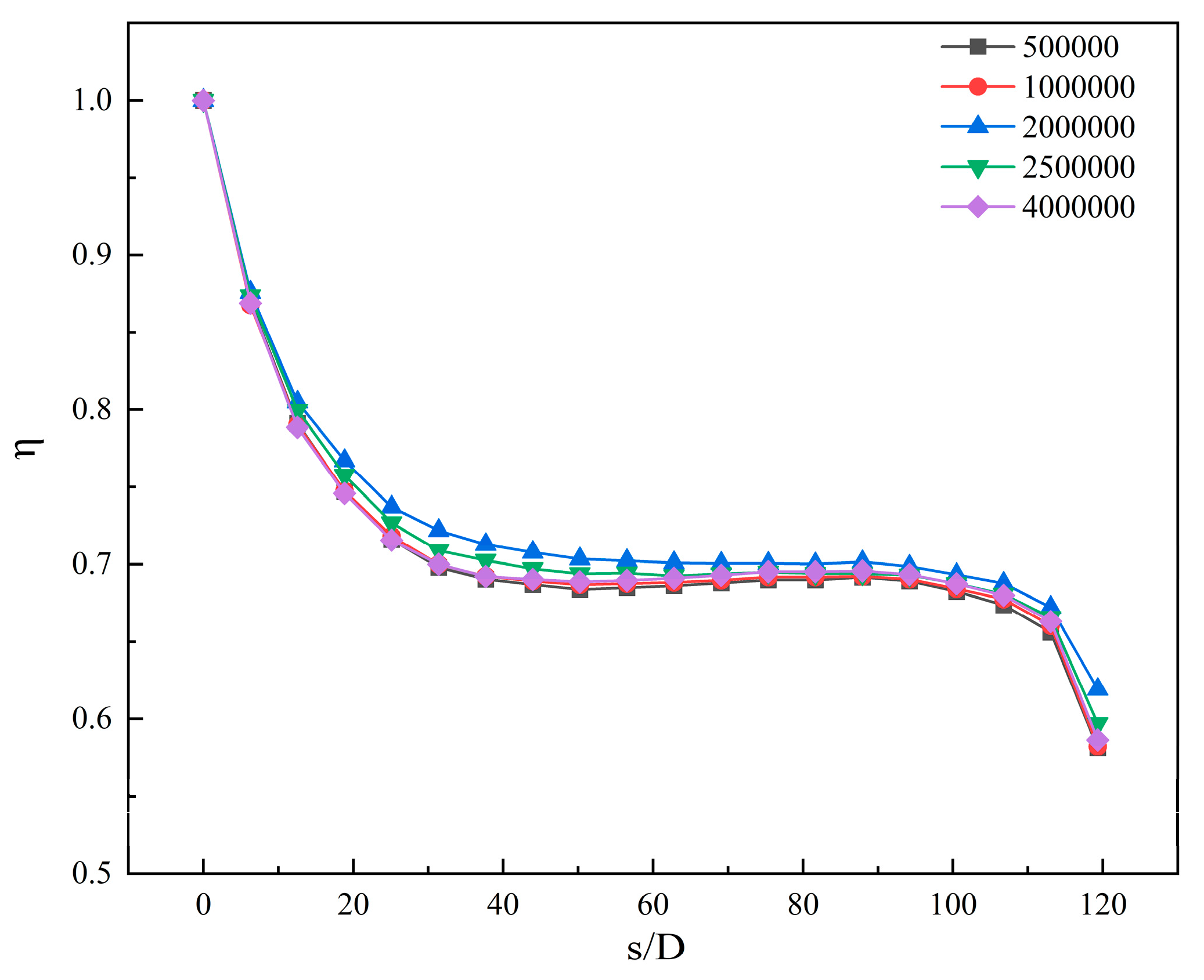
Figure 5: Verification of the grid-independence.
In the previously reported works in the literature, the numerical optimization of shaped cooling holes has been performed on a single air film hole cooling design [26,27,28]. However, for reflux combustion chamber flame cylinder cooling applications, the cooling is typically achieved through arrays of film cooling holes. Therefore, the influence of hole-to-hole interaction must be taken into account. As shown in Fig. 6, the ultra-long rhombic arrangement was adopted. Compared to in-line and cross-flow arrangements, the utilization of an ultra-long rhombic air film hole arrangement not only facilitates obtaining an excellent air film layer but also improves the average adiabatic air film cooling efficiency [29]. S is the longitudinal spacing of the air film holes, and P denotes the transverse spacing of the air film holes and both represent the distance between adjacent hole edges, where P/D = 4, and S/D = 8. The primary geometric parameters of the fan-shaped film cooling holes used in this work include the diameter of the film cooling holes inlet (D), the length of the rounded film cooling holes (L), the injection angle of the film cooling holes (
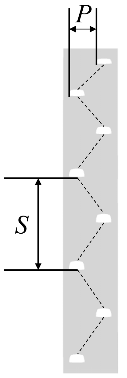
Figure 6: Arrangement of film cooling holes.
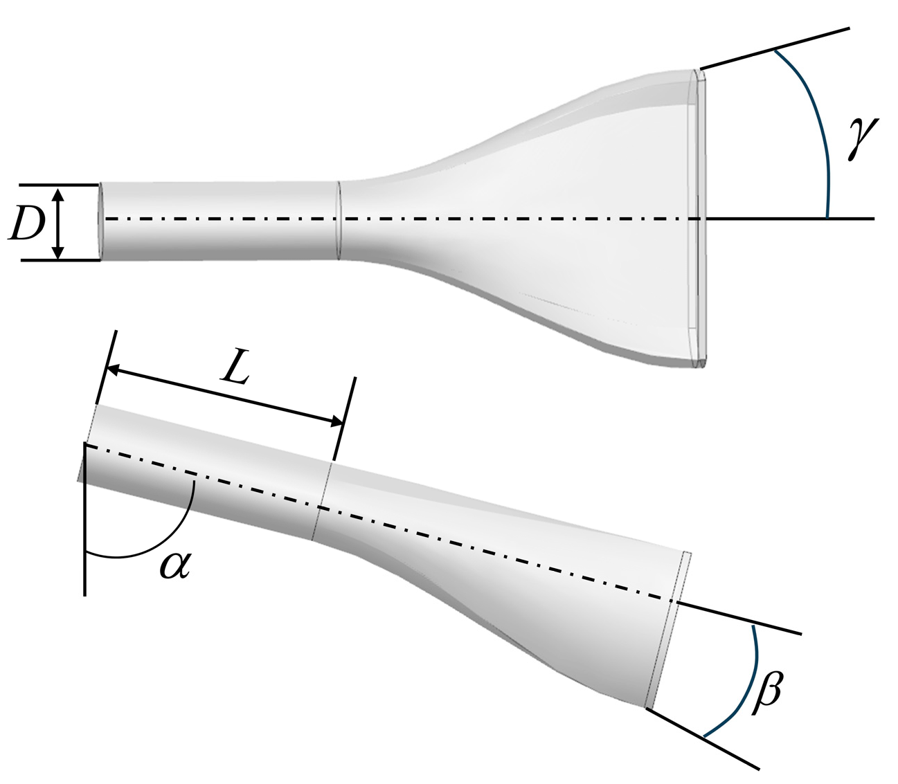
Figure 7: Geometrical parameter diagram.
Fig. 8 depicts the optimization process used in this work based on the combination of the surrogate-based model GPR and the Bayesian optimization algorithm.
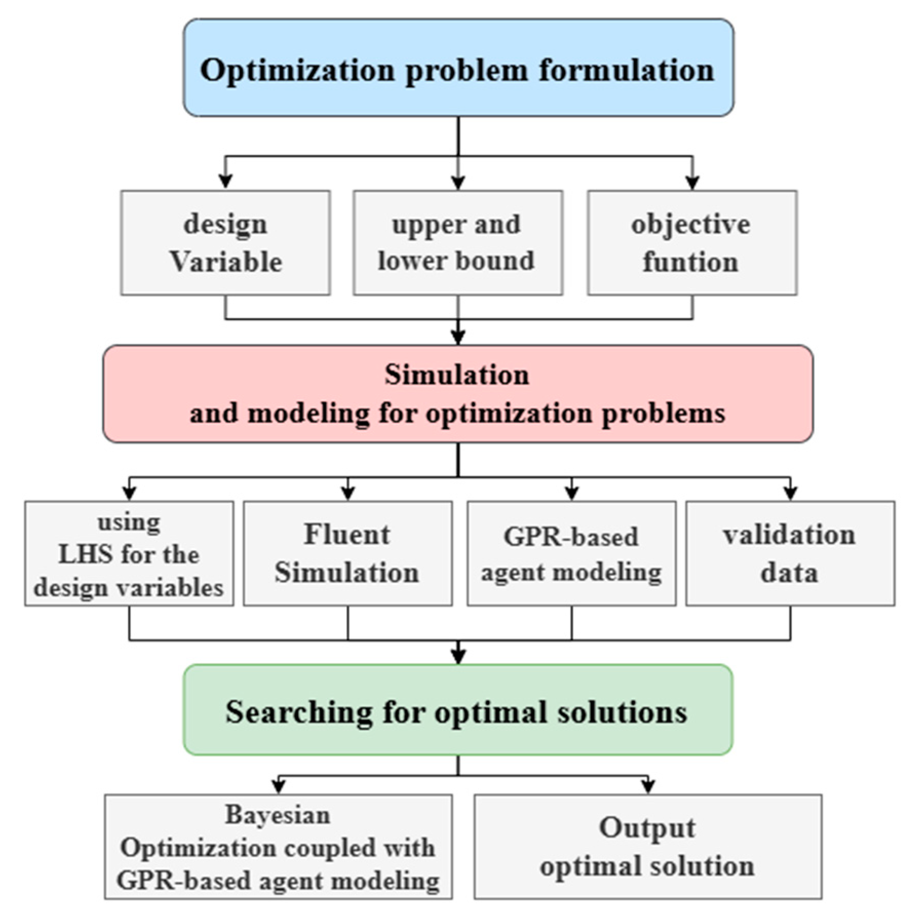
Figure 8: Schematic diagram of the optimization design process.
The initial step involves designing the variables and objective functions for the optimization problem. The forward and lateral inclination angles of the fan-shaped air film holes each play a vital role in the air film cooling process. As the forward inclination angle increases, the jet’s flow component and the distance of the reverse symmetric vortex downstream increase. The latter effect is conducive to improving the air film’s adherence to the wall, thereby enhancing the cooling effect. On the other hand, the lateral inclination angle of the air film holes mainly affects the spreading component of the jet, which in turn enhances the spreading coverage of the air film. A larger lateral expansion angle results in more extensive air film spreading, promoting a more uniform coverage. At the same time, the lateral inclination angle may also affect the degree of mixing between the cooling airflow and the main flow, which in turn affects the cooling efficiency. Therefore, four individual geometric parameters, namely, incident angle (
Table 2: Design variables.
| Design Variables | Lower Bound | Upper Bound |
|---|---|---|
| 40 | 60 | |
| 0 | 15 | |
| 10 | 20 | |
| 3 | 5 |
There are many choices regarding the setting of the objective function, such as the inverse of the spatially averaged air film cooling efficiency and the actual and theoretical kinetic energy fluxes at the mixing plane [30]. This work focused on the problem of optimizing the thermal performance of sector film cooling technology, which defines an independent objective function: the average adiabatic film cooling efficiency, which is defined in Eq. (2). This efficiency index is a crucial parameter for measuring the cooling effect. Therefore, the core objective of this work was to maximize this efficiency using optimization to achieve optimal thermal protection performance.
Therefore, the optimally independent objective function can be constructed as follows:
The second step is to establish a surrogate model. During the optimization process, the original problem may be relatively complex, difficult to model, and computationally expensive [31]. On the contrary, the surrogate model simplifies or approximates the original problem. Taking into account that surrogate models play an important role in optimization problems, they can help solve the original problem’s complexity and difficulty and facilitate the application and development of optimization algorithms. For this reason, they are widely used by the scientific community. In this work, the Gaussian Process Regression (GPR) model was used to construct the surrogate model. The main assumption of the model is the utilization of a Gaussian process for each possible function in the function space. This process is updated using the observed data, ultimately resulting in a posterior distribution that is used to predict the output of the new data. During the construction of the GPR-based surrogate model, the sample space was designed using the Latin Hypercube Sampling (LHS) method for 44 sets of samples [32], and the sampling points are shown in Fig. 9. LHS is a multidimensional random sampling method for designing experiments or sampling the parameter space. The data (cooling efficiency) of the sampling points at different blowing ratios are obtained by conducting CFD simulations. The simulated 36 sets of data (as shown in Table 3) were taken as training samples, and the GPR-based surrogate model was constructed using the Python software to train the surrogate model through 36 sets of training samples. To validate and optimize the surrogate model, 8 sets of data were taken as test samples (as listed in Table 4). Fig. 10 and Fig. 11 compare the GPR-based cooling efficiency prediction results and CFD’s cooling efficiency simulation results under M = 1.0 and M = 1.5, respectively. The cooling efficiency errors relative to the simulation data were all within 5%, the GPR-based proxy model was suitable for this study, and the cooling efficiency prediction data successfully met the requirements.
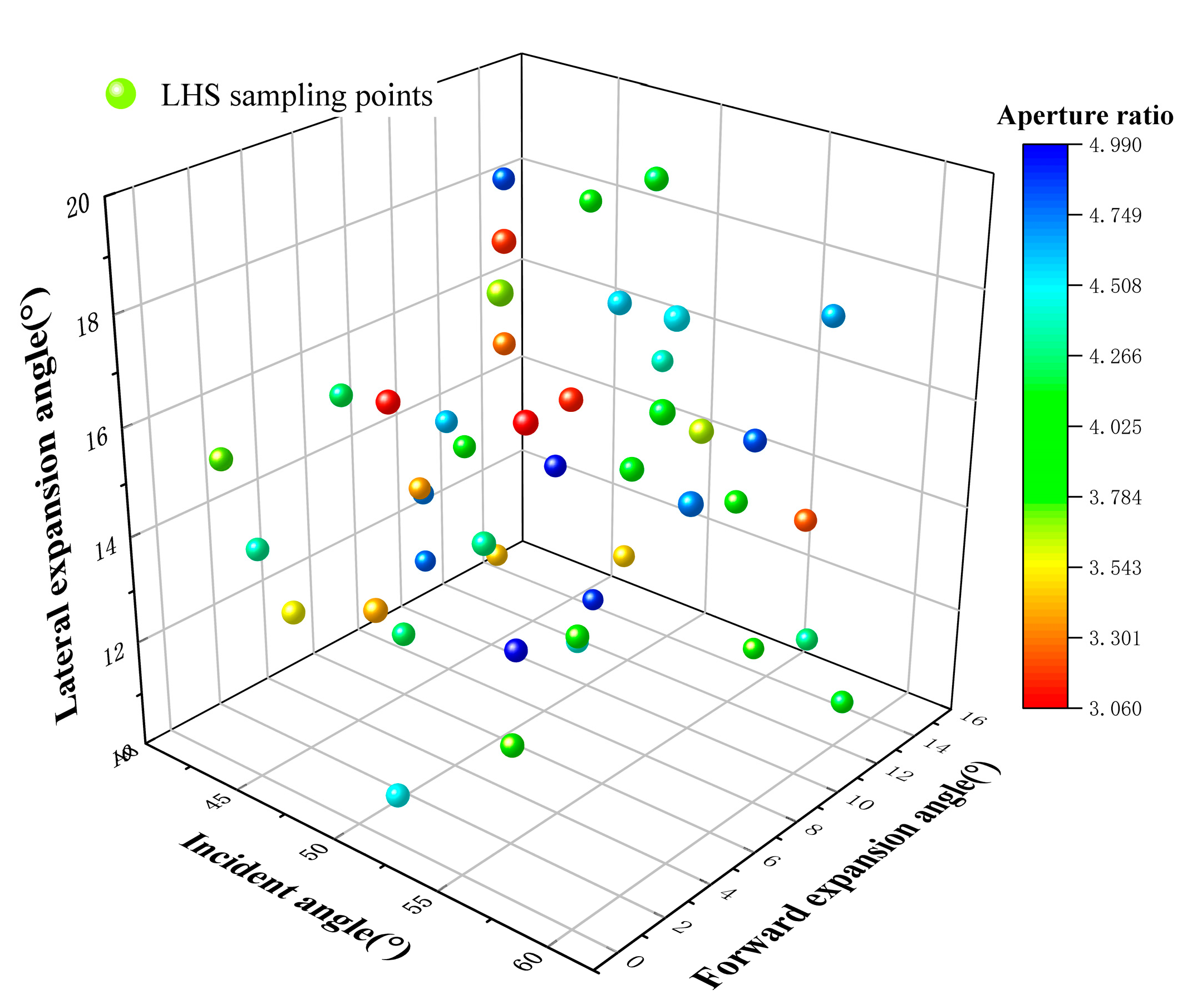
Figure 9: Schematic diagram of Latin hypercube sampling points.
Table 3: Training samples.
| No. | ||||||
|---|---|---|---|---|---|---|
| 1 | 55.3 | 1.4 | 19.8 | 3.7 | 0.713 | 0.794 |
| 2 | 43.8 | 7.8 | 13.5 | 3.4 | 0.772 | 0.843 |
| 3 | 49.1 | 14.3 | 15.4 | 4.4 | 0.722 | 0.794 |
| 4 | 52.9 | 8.5 | 18.0 | 4.6 | 0.703 | 0.770 |
| 5 | 48.0 | 3.6 | 12.3 | 4.2 | 0.722 | 0.797 |
| 6 | 52.8 | 10.2 | 19.9 | 4.1 | 0.706 | 0.762 |
| 7 | 43.2 | 1.5 | 13.7 | 4.3 | 0.754 | 0.828 |
| 8 | 44.3 | 11.3 | 18.8 | 4.8 | 0.732 | 0.799 |
| 9 | 51.9 | 3.7 | 14.6 | 4.3 | 0.729 | 0.802 |
| 10 | 43.1 | 0.4 | 15.6 | 3.8 | 0.754 | 0.827 |
| 11 | 57.9 | 13.3 | 17.5 | 4.7 | 0.688 | 0.756 |
| 12 | 45.4 | 7.8 | 15.0 | 4.6 | 0.733 | 0.806 |
| 13 | 50.8 | 0.2 | 14.1 | 3.4 | 0.731 | 0.810 |
| 14 | 45.1 | 10.2 | 11.8 | 3.4 | 0.750 | 0.823 |
| 15 | 56.3 | 10.7 | 14.5 | 3.9 | 0.702 | 0.778 |
| 16 | 54.6 | 2.4 | 11.7 | 3.8 | 0.698 | 0.776 |
| 17 | 59.8 | 4.9 | 16.2 | 4.7 | 0.681 | 0.746 |
| 18 | 44.5 | 4.1 | 16.2 | 4.2 | 0.745 | 0.819 |
| 19 | 55.6 | 6.5 | 15.9 | 4.0 | 0.700 | 0.776 |
| 20 | 50.6 | 1.1 | 10.4 | 4.5 | 0.705 | 0.774 |
| 21 | 49.2 | 2.2 | 17.1 | 3.1 | 0.777 | 0.854 |
| 22 | 47.0 | 8.9 | 16.5 | 3.3 | 0.764 | 0.838 |
| 23 | 54.1 | 5.7 | 12.8 | 3.9 | 0.704 | 0.783 |
| 24 | 51.4 | 8.2 | 11.6 | 4.4 | 0.709 | 0.781 |
| 25 | 48.8 | 9.6 | 14.3 | 5.0 | 0.716 | 0.785 |
| 26 | 57.6 | 12.8 | 13.8 | 3.2 | 0.710 | 0.788 |
| 27 | 41.6 | 9.8 | 11.3 | 4.8 | 0.745 | 0.815 |
| 28 | 47.6 | 12.6 | 10.7 | 4.9 | 0.722 | 0.792 |
| 29 | 58.6 | 5.3 | 19.0 | 4.5 | 0.687 | 0.755 |
| 30 | 52.4 | 4.6 | 12.5 | 5.0 | 0.703 | 0.768 |
| 31 | 46.8 | 7.3 | 14.9 | 4.0 | 0.731 | 0.801 |
| 32 | 54.8 | 2.8 | 17.3 | 3.1 | 0.741 | 0.822 |
| 33 | 53.2 | 6.2 | 16.8 | 3.1 | 0.747 | 0.826 |
| 34 | 58.2 | 7.0 | 16.8 | 3.6 | 0.705 | 0.785 |
| 35 | 49.9 | 11.8 | 12.2 | 3.5 | 0.730 | 0.806 |
| 36 | 56.4 | 14.5 | 10.9 | 4.2 | 0.702 | 0.772 |
Table 4: Test sample.
| No. | ||||||
|---|---|---|---|---|---|---|
| 1 | 47.6 | 12.2 | 18.6 | 3.9 | 0.744 | 0.814 |
| 2 | 59.4 | 13.1 | 10.5 | 4.1 | 0.684 | 0.759 |
| 3 | 42.5 | 9.1 | 12.9 | 4.7 | 0.746 | 0.817 |
| 4 | 53.7 | 14.7 | 10.2 | 3.8 | 0.706 | 0.782 |
| 5 | 46.0 | 0.8 | 13.1 | 3.5 | 0.757 | 0.833 |
| 6 | 56.8 | 10.9 | 15.6 | 4.8 | 0.689 | 0.756 |
| 7 | 59.1 | 4.3 | 17.8 | 4.1 | 0.686 | 0.761 |
| 8 | 50.3 | 6.0 | 19.2 | 3.2 | 0.766 | 0.842 |
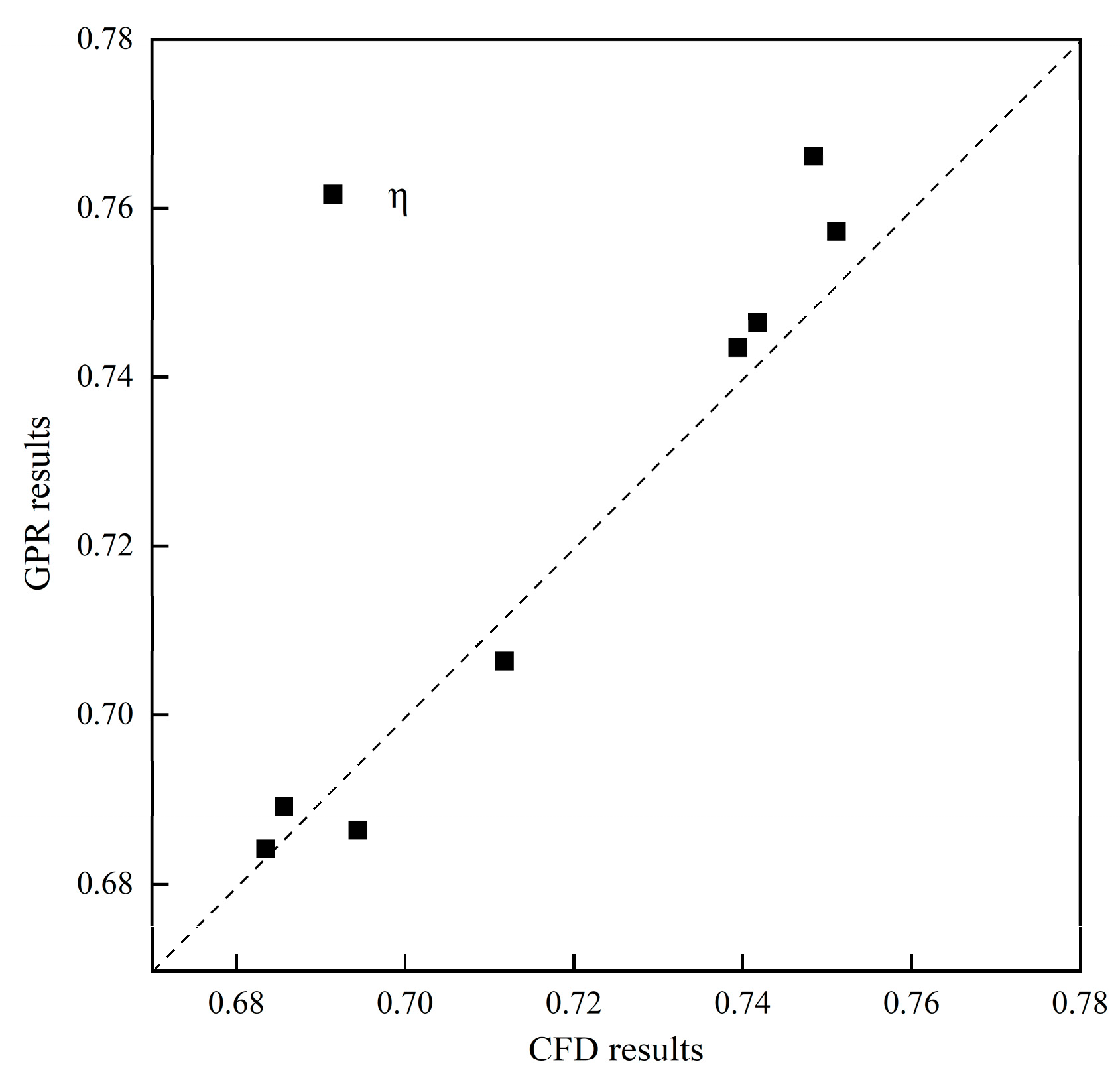
Figure 10: Comparison between the GPR-based prediction results and the CFD simulation results for M = 1.0 condition.
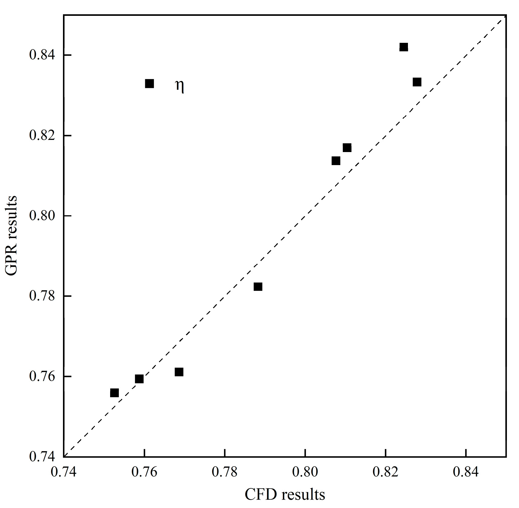
Figure 11: Comparison between the GPR-based prediction results and the CFD simulation results for M = 1.5 condition.
The third step was to solve the maximum solution, build the Bayesian optimization algorithm and GPR-based surrogate model coupling code through Python, and go through continuous debugging and optimization to get the optimal solution.
3 Optimization Results and Discussion
Three reference cases and optimization cases (Opt) for M = 1.0 and M = 1.5 are given in Table 5 and Table 6, respectively. The first reference case (Ref. 1) was chosen as the fan-shaped air film aperture studied by Zamiri et al. [33], where the following parameters were chosen: an incidence angle of 60°, a forward inclination of 10°, a lateral inclination of 10°, and an aperture ratio of 3. The second reference case (Ref. 2) was Kim et al.’s study [34] of the Crescent-shaped air-film aperture with the same parameter selection as Case 1. The third case (Ref. 3) was chosen as the optimized parameters of the back-swept fan-shaped air-film orifice studied by Huang et al. The parameters were chosen as the optimized parameters of the air-film orifice: an incidence angle of 50.3°, a forward inclination angle of 9.8°, a sideways inclination angle of 19.5°, an aperture ratio of 3. 2 As can be seen from Table 5 and Table 6, the cooling efficiency of the fan-shaped film cooling hole is affected by the blowing ratio and the optimized parameters.
At M = 1.0, the optimized fan-shaped air film holes can significantly increase the average adiabatic cooling efficiency at the wall of the concave wall by 15.2% compared to Ref. 1 and 7.7% compared to Ref. 3. At M = 1.5, a high blowing ratio improves the average adiabatic cooling efficiency of the concave wall by 12.3% compared to Ref. 1 and by 5.5% compared to Ref. 3.
Table 5: Optimization case and reference case for M = 1.0.
| No. | ||||||
|---|---|---|---|---|---|---|
| Ref. 1 | 60.00 | 10.00 | 10.00 | 3.0 | 0.703 | |
| Ref. 2 | 60.00 | 3.0 | 0.686 | |||
| Ref. 3 | 50.30 | 9.80 | 19.5 | 3.2 | 0.766 | |
| Opt | 40.00 | 0.00 | 20.00 | 3.0 | 0.801 | 0.822 |
Table 6: Optimization case and reference case for M = 1.5.
| No. | ||||||
|---|---|---|---|---|---|---|
| Ref. 1 | 60.00 | 10.00 | 10.00 | 3.0 | 0.782 | |
| Ref. 2 | 60.00 | 3.0 | 0.756 | |||
| Ref. 3 | 50.30 | 9.80 | 19.5 | 3.2 | 0.842 | |
| Opt | 40.00 | 0.00 | 20.00 | 3.0 | 0.873 | 0.891 |
3.2 Analysis of Cooling Efficiency Distribution and Temperature Field Characteristics on Concave Wall Surfaces
Fig. 12 and Fig. 13 show the distribution of the cooling efficiencies on the concave wall surface for blowing ratios of 1.0 and 1.5, respectively. The topmost region of the concave wall exhibits a cooling efficiency close to 1 due to the initial film cooling hole effect. A region of low cooling efficiency is formed in the middle of the wall, which is significantly minimized by the parameter-optimized Opt case. Compared to the Ref. 1, Ref. 2, and Ref. 3 models, the Opt case showed a significant advantage in the cooling efficiency of the concave wall under the same operating conditions. This improvement can be primarily attributed to two key features of the Opt case design: the increased lateral inclination, which promotes the cold airflow coverage over a broader range of the concave wall and extends the trailing effect; and reduced forward inclination, which minimizes aerodynamic losses and enhances the cold airflow’s adherence to the wall surface. Under high blowing ratio conditions, the Opt case showed significantly higher cooling efficiency in the lower region of the film cooling holes, forming broad bands of high cooling efficiency that offer enhanced thermal protection for the concave wall.
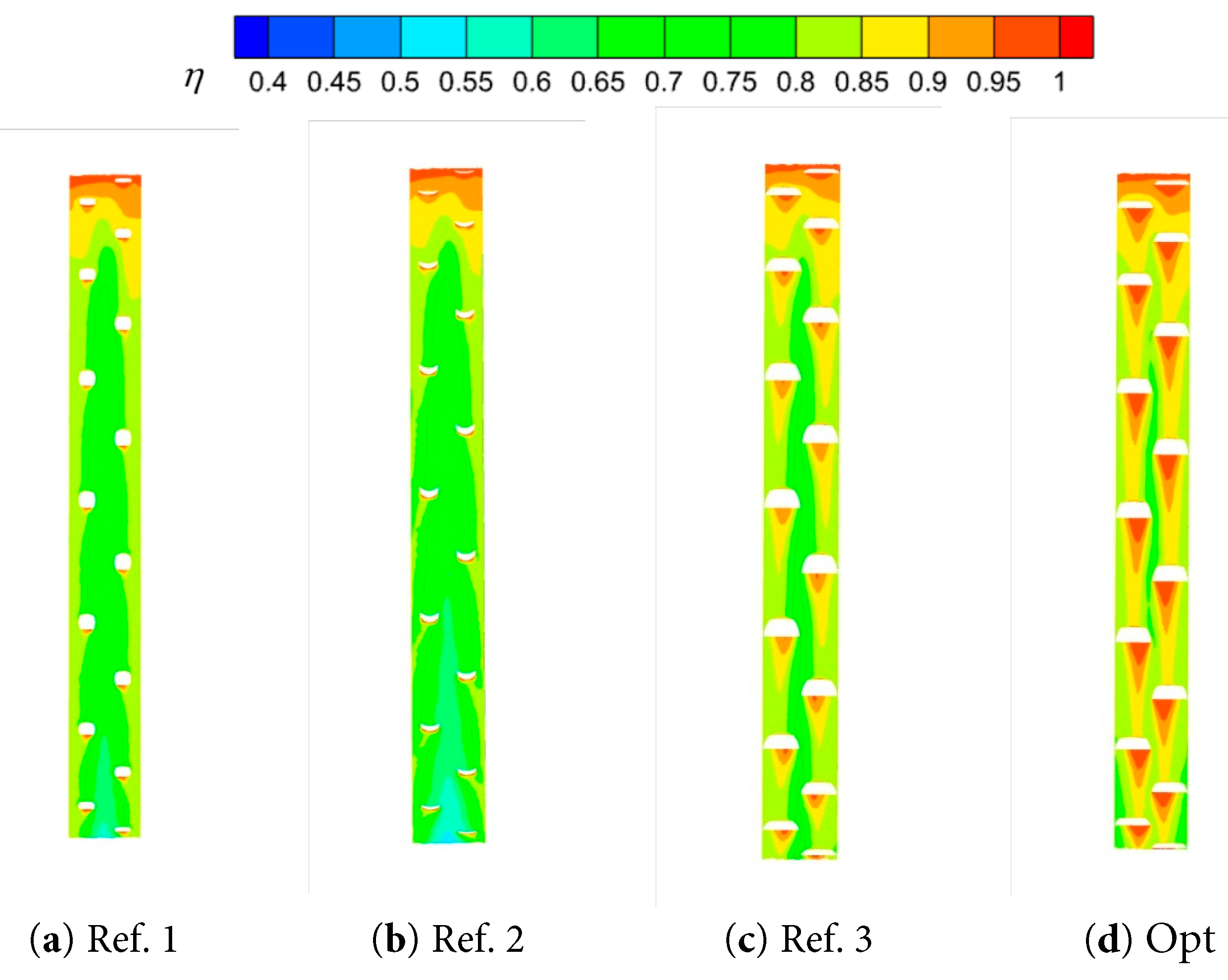
Figure 12: Comparison of the cooling efficiency of M = 1.0 concave wall surface.
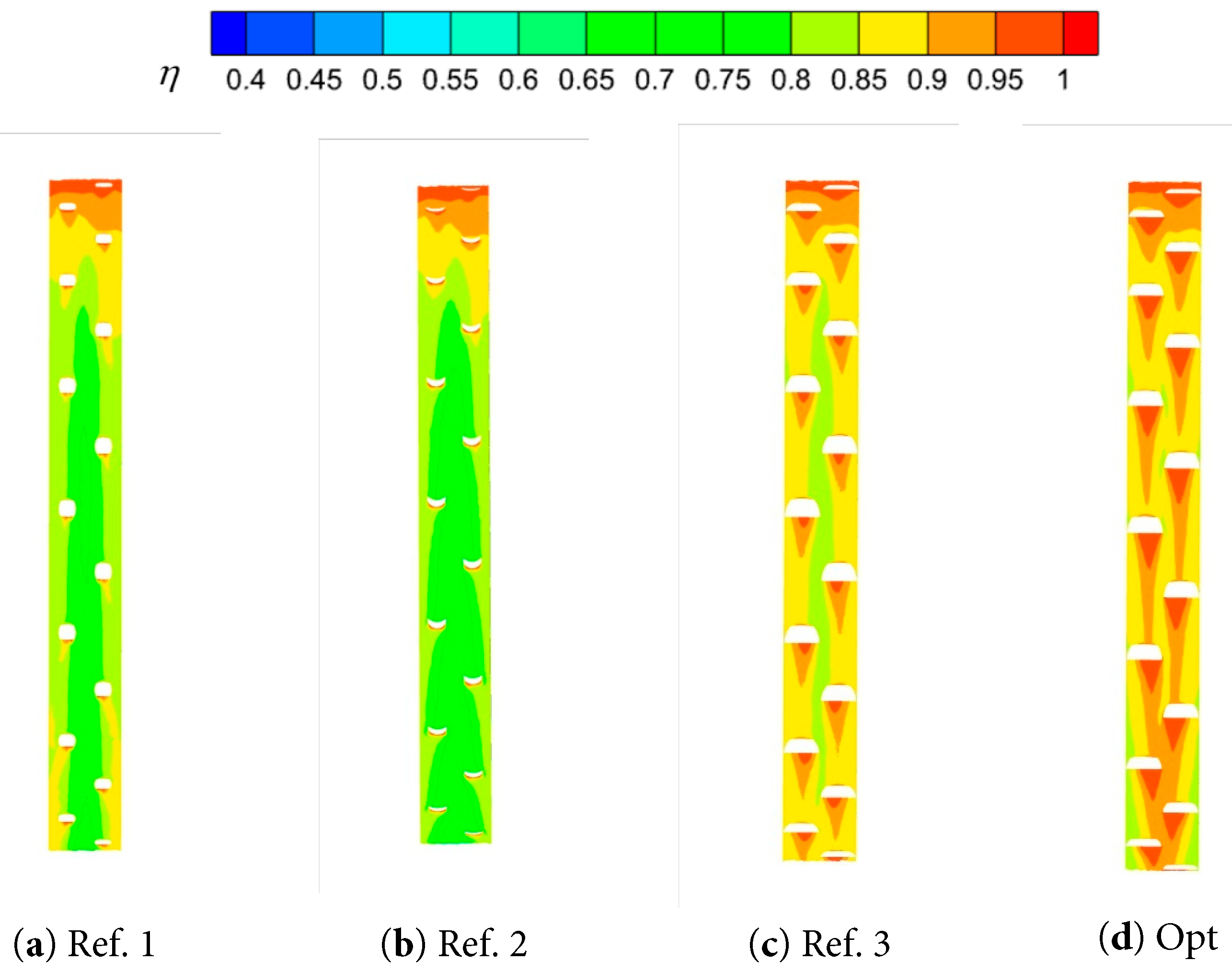
Figure 13: Comparison of the cooling efficiency of M = 1.5 concave wall surface.
Fig. 14 shows the temperature distribution and flow line changes for different models of the concave wall at blowing ratios of 1.0 and 1.5, respectively. As can be observed, the cold airflow from the fan-shaped film cooling holes outflow can be evenly spread along the concave wall surface, forming a layer of low-temperature protective layer; this protective layer effectively blocks the high-temperature hot airflow on the wall of the direct impact, which reduces the risk of deformation of the wall surface of the extensive bend materials due to thermal stress. As the blowing ratio increases, the temperature near the surface decreases, and the coverage (thickness) of the low-temperature protective layer significantly expands. This trend suggests that high blowing ratio conditions are more favourable for improving cooling efficiency and enhancing thermal protection of the wall. In particular, the flow behaviour of the cold airflow after passing through the film cooling holes in the optimized Opt case exhibits better characteristics. More specifically, the Opt case produces a more pronounced cooling wake and a longer flow path for the cold airflow, resulting in a broader and longer cooling effect on the concave wall.
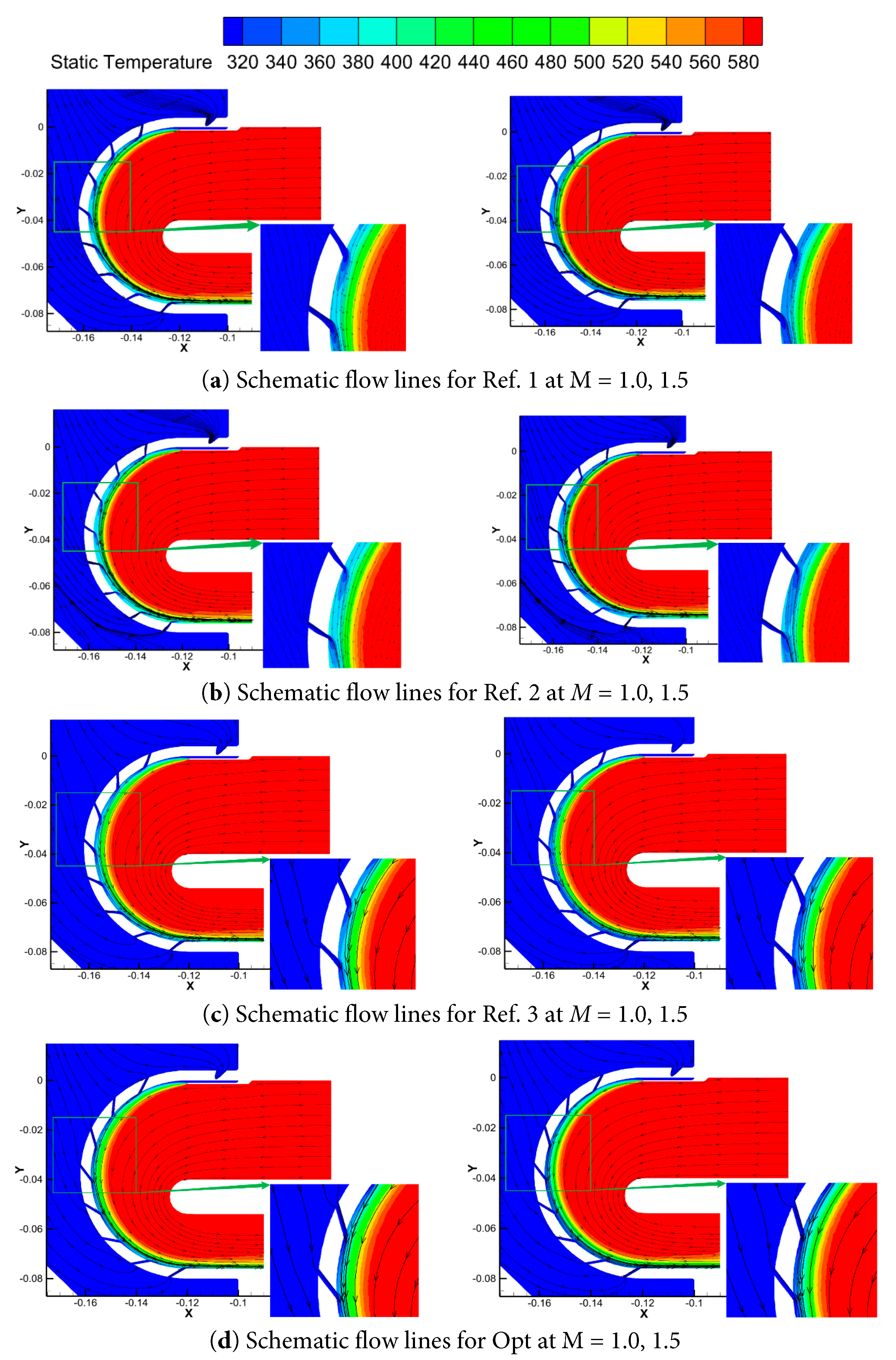
Figure 14: Schematic flow lines of Ref. 1, Ref. 2, Ref. 3, and Opt for different blowing ratios.
Fig. 15 presents the temperature distribution at different locations along the wall surface of the concave wall for the reference case Ref. 3, and the optimized case Opt. In all cases, the temperature starts at 300°C at the beginning of the concave wall, and then, it sharply rises before gradually decreasing. The optimized Opt case effectively reduces the wall temperature, with its temperature distribution at a blowing ratio of 1.0 comparable to Ref. 3 at a blowing ratio of 1.5, underscoring the Opt case’s advantage in cooling efficiency. The fluctuating temperature changes on the concave wall can be attributed to the extra-long diamond-shaped arrangement of the air film holes. This unique arrangement affects the distribution and flow path of the cold airflow, contributing to the complexity of the wall’s temperature distribution.
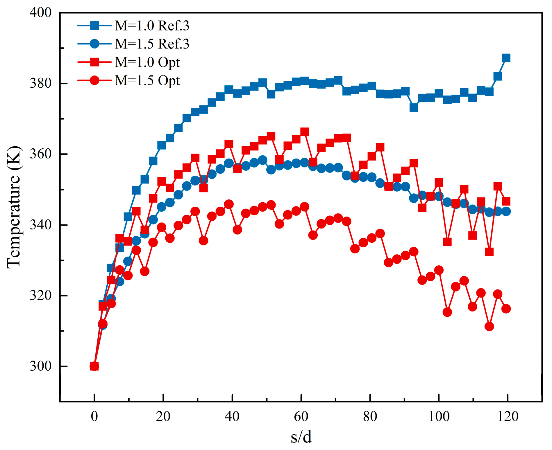
Figure 15: Comparison of Ref. 3 and Opt temperatures along the concave wall.
Fig. 16 and Fig. 17 present the distribution of the temperature comparison in three specific cross-sections along the arc length for different blowing ratios. In the two end regions of the wall of the big bend, the demarcation between the cold and the hot air streams is significantly lower compared to the middle region. The thin film layer formed by the cold air is thinner in the central region of the cross-section and relatively thicker near the edge of the slit. This effect can be attributed to the fact that the prevailing airflow tends to be closer to the film cover in the central region. In addition, at the lower end of all the cross-sections examined, a thin layer of cold air is present, effectively protecting the wall of the large bend. Specifically, the cooling regions formed by cross-section s/D = 28.9 and s/D = 104.6 were similar in thickness, and both were smaller than the thickness of the cooling region for cross-section s/D = 63.7. Under a higher blowing ratio, the downstream region of cross-section s/D = 63.7 forms a pair of vortex structures due to the interaction between the cold airflow and the crossflow. It is also worth noting that this pair of vortices exhibits asymmetric properties due to the asymmetry of the air film hole arrangement.
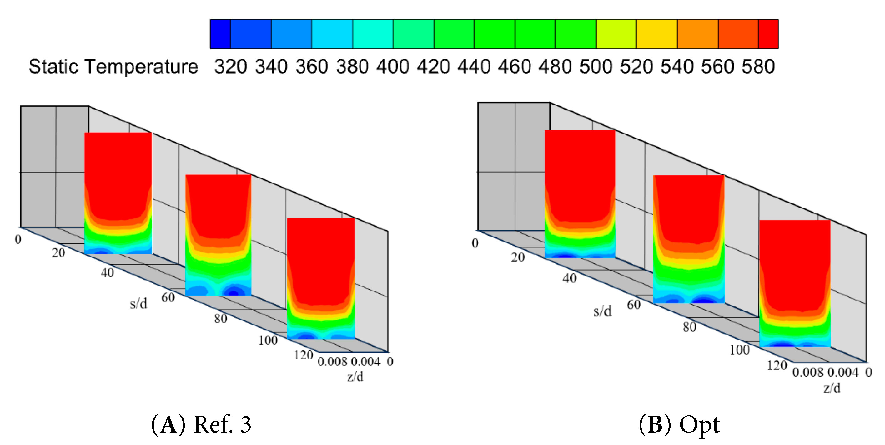
Figure 16: Temperature comparison along the arc length direction for certain cross-sections at M = 1.0.
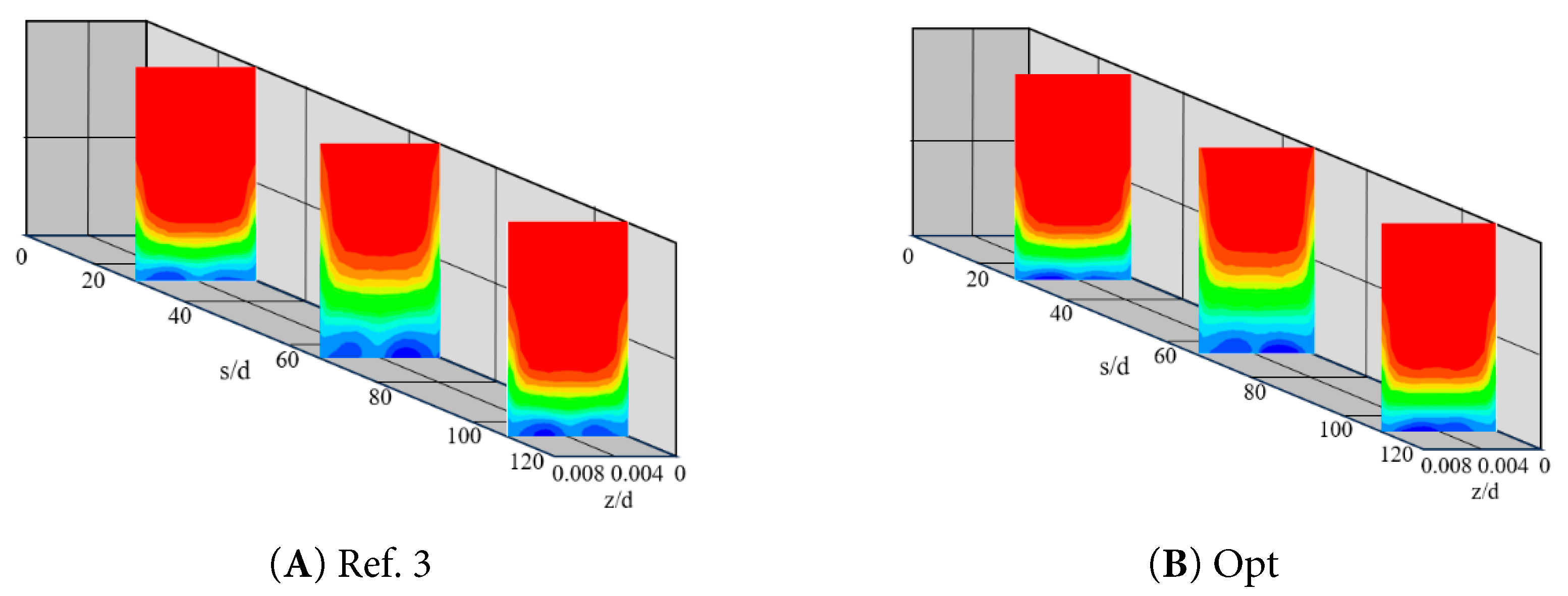
Figure 17: Temperature comparison along the arc length direction for certain cross-sections at M = 1.5.
In this work, a single-objective optimization design was conducted to enhance the adiabatic cooling efficiency of the concave wall’s air film cooling holes with an initial film cooling hole. Numerical modelling and CFD simulation were used for data establishment. The fan-shaped air film holes were arranged in an extra-long rhombic row, and the opening rate was chosen to be 2.45%. Among the main geometrical parameters of the fan-shaped holes, the incidence angle, aperture ratio, and forward and lateral inclination were chosen as the design variables. When the thermal performance of the air film holes was optimized, the objective function was selected as the average cooling efficiency of the concave wall and simulation optimization was carried out at two classical blowing ratios of M = 1.0 and M = 1.5.
The LHS was used to sample the selected range of design variables, and the Gaussian process regression was employed to construct a surrogate model to train and validate the established data. When the trained model was validated against the validation set, the errors at different blowing ratios were below 5%, and the trained model was suitable for the following optimization process. The Gaussian process regression and Bayesian optimization algorithm were coupled to find the optimal solution for the data within the design variables. The optimal solutions obtained were
The principal novelty of this work lies in the integrated optimization methodology that systematically couples geometric parameterization, surrogate model, and Bayesian optimization for concave-wall film cooling under multiple blowing ratios. This framework not only quantifies the sensitivity of cooling performance to geometric variations but also provides an efficient design exploration strategy, offering data-driven guidance for achieving optimized cooling configurations. While the current single-objective approach successfully improves cooling efficiency, it does not account for other critical engineering criteria such as cooling uniformity and pressure loss. Therefore, future research will develop a multi-objective optimization framework incorporating these competing performance metrics to generate a Pareto-optimal solution set, thereby supporting more comprehensive and practical design decisions.
Acknowledgement:
Funding Statement: This work was supported by the Jiangsu Association for Science and Technology, grant number SKX 0225 089; the National Natural Science Foundation of China, grant number 52476027.
Author Contributions: Methodology: Xiaowen Song; software: Yanzhao Yang; validation: Yanzhao Yang and Zhiying Deng; formal analysis: Yanzhao Yang; investigation: Yanzhao Yang; resources: Xiaowen Song; data curation: Yanzhao Yang and Zhiying Deng; writing—original draft preparation: Yanzhao Yang; writing—review and editing: Yanzhao Yang and Zhiying Deng; visualization: Xiaowen Song and Jianyang Yu; supervision: Xiaowen Song and Jianyang Yu; funding acquisition: Yanzhao Yang and Jianyang Yu. All authors reviewed the results and approved the final version of the manuscript.
Availability of Data and Materials: The datasets generated during and/or analyzed during the current study are available from the corresponding author on reasonable request.
Ethics Approval: Not applicable.
Conflicts of Interest: The authors declare no conflicts of interest to report regarding the present study.
Abbreviations
| Parameter Notation | Parameter Definition | |
| D | Film cooling hole diameter | |
| L | rounded film cooling holes length | |
| M | blowing ratio | |
| F | objective function | |
| P | hole-to-hole pitch | |
| p | pressure | |
| S | film cooling hole longitudinal spacing | |
| s | concave wall archway length | |
| T | temperature | |
| u | velocity | |
| α | injection angle of hole | |
| β | forward expansion angle of film cooling hole | |
| γ | lateral expansion angle of film cooling hole | |
| δ | aperture ratio | |
| η | film cooling effectiveness | |
| x, y, z | coordinates | |
| ∞ | main stream of gas | |
| c | secondary stream of gas | |
| m | main channel inlet | |
| o | outlet | |
| w | concave wall | |
| si | secondary channel inlet |
References
1. Marudhappan R , Udayagiri C , Reddy KH . Combustion chamber design and reaction modeling for aero turbo-shaft engine. Aircr Eng Aerosp Technol. 2018; 91( 1): 94– 111. doi:10.1108/aeat-10-2017-0217. [Google Scholar] [CrossRef]
2. Zhang J , Sun Y , Li J , He X . Study on the hybrid cooling of the flame tube in a small triple-swirler combustor. Energies. 2020; 13( 21): 5554. doi:10.3390/en13215554. [Google Scholar] [CrossRef]
3. Nourin FN , Amano RS . Review of gas turbine internal cooling improvement technology. J Energy Resour Technol. 2021; 143( 8): 080801. doi:10.1115/1.4048865. [Google Scholar] [CrossRef]
4. Guo C , Wang B , Kang Z , Zhang W , Zheng H . Numerical simulation study on cooling characteristics of a new type of film hole. J Therm Sci. 2021; 30( 1): 210– 9. doi:10.1007/s11630-020-1288-0. [Google Scholar] [CrossRef]
5. Dutta S , Kaur I , Singh P . Review of film cooling in gas turbines with an emphasis on additive manufacturing-based design evolutions. Energies. 2022; 15( 19): 6968. doi:10.3390/en15196968. [Google Scholar] [CrossRef]
6. Jia Y , Liu Y , He X , Xia G , Shi Z . Review of turbine film cooling technology for marine gas turbines. Processes. 2025; 13( 5): 1424. doi:10.3390/pr13051424. [Google Scholar] [CrossRef]
7. Shine SR , Nidhi SS . Review on film cooling of liquid rocket engines. Propuls Power Res. 2018; 7( 1): 1– 18. doi:10.1016/j.jppr.2018.01.004. [Google Scholar] [CrossRef]
8. Liu R , Li H , Lin J , You R , Tao Z . An experimental and numerical investigation of film cooling effectiveness on a gas turbine blade tip region. Int J Therm Sci. 2022; 177: 107544. doi:10.1016/j.ijthermalsci.2022.107544. [Google Scholar] [CrossRef]
9. Wang B , Wang F , Zhang X , Wang J , Xue T . Numerical analysis of cooling efficiency for turboshaft engines with converging-diverging film cooling holes. Int J Therm Sci. 2023; 185: 108044. doi:10.1016/j.ijthermalsci.2022.108044. [Google Scholar] [CrossRef]
10. Goldstein RJ , Eckert ERG , Burggraf F . Effects of hole geometry and density on three-dimensional film cooling. Int J Heat Mass Transf. 1974; 17( 5): 595– 607. doi:10.1016/0017-9310(74)90007-6. [Google Scholar] [CrossRef]
11. Yu M , Xuan D . Influence of converging slot-holes (consoles) with different transition surfaces on film cooling performance. J Phys Conf Ser. 2022; 2280( 1): 012019. doi:10.1088/1742-6596/2280/1/012019. [Google Scholar] [CrossRef]
12. Luo Y , Li H , Zhou Z , Xie G , Meng L , Liu L , et al. Experimental and numerical investigation on the film cooling performance of the novel B-shaped and C-shaped holes. Appl Therm Eng. 2025; 277: 127114. doi:10.1016/j.applthermaleng.2025.127114. [Google Scholar] [CrossRef]
13. Schroeder RP , Thole KA . Adiabatic effectiveness measurements for a baseline shaped film cooling hole. J Turbomach. 2022; 144( 12): 121003. doi:10.1115/1.4055271. [Google Scholar] [CrossRef]
14. Huang KN , Zhang JZ , Wang CH , Tan XM . Film cooling characteristics of serrated trenched-hole on curved surfaces. Int J Therm Sci. 2021; 164: 106919. doi:10.1016/j.ijthermalsci.2021.106919. [Google Scholar] [CrossRef]
15. Jia Y , Liu Y , Meng Z , Yin W , Hua W . Numerical study on film cooling effectiveness from spiral-channel hole. Int Commun Heat Mass Transf. 2023; 143: 106716. doi:10.1016/j.icheatmasstransfer.2023.106716. [Google Scholar] [CrossRef]
16. Jae S , Jun K , Cheol L , Su K , Shin P , Don L . Optimization of the configuration of the laidback fan-shaped film cooling hole with a lateral expansion angle of 10 degrees. Appl Therm Eng. 2019; 153: 379– 89. doi:10.1016/j.applthermaleng.2019.03.029. [Google Scholar] [CrossRef]
17. Baek SI , Lee HK , Jeong Y , Ryu J . Large eddy simulation of film cooling for a forward expansion hole under main flow oscillation. Int J Heat Mass Transf. 2024; 218: 124755. doi:10.1016/j.ijheatmasstransfer.2023.124755. [Google Scholar] [CrossRef]
18. Fraas M , Glasenapp T , Schulz A , Bauer HJ . Optimized inlet geometry of a laidback fan-shaped film cooling hole–Experimental study of film cooling performance. Int J Heat Mass Transf. 2019; 128: 980– 90. doi:10.1016/j.ijheatmasstransfer.2018.09.035. [Google Scholar] [CrossRef]
19. Johnson PL , Shyam V . Hah C Reynolds-Averaged Navier-Stokes Solutions to Flat Plate Film Cooling Scenarios [Internet]. [cited 2025 Dec 22]. Available from: https://ntrs.nasa.gov/api/citations/20110012464/downloads/20110012464.pdf. [Google Scholar]
20. Chen L , Bao A , Zhang Y , Chen D , Guan J , Dai R . Surrogate-based optimization and experiment validation of a fan-shaped film cooling hole with a large lateral space. Appl Therm Eng. 2022; 207: 118145. doi:10.1016/j.applthermaleng.2022.118145. [Google Scholar] [CrossRef]
21. Huang Y , Zhang JZ , Wang CH . Multi-objective optimization of round-to-slot film cooling holes on a flat surface. Aerosp Sci Technol. 2020; 100: 105737. doi:10.1016/j.ast.2020.105737. [Google Scholar] [CrossRef]
22. Zhu R , Xie G , Li S , Lei J . Experimental investigation and numerical analysis on effects of swirling coolant on flow characteristics and film cooling performance. Int Commun Heat Mass Transf. 2022; 135: 106112. doi:10.1016/j.icheatmasstransfer.2022.106112. [Google Scholar] [CrossRef]
23. Sinha AK , Bogard DG , Crawford ME . Film-cooling effectiveness downstream of a single row of holes with variable density ratio. J Turbomach. 1991; 113( 3): 442– 9. doi:10.1115/1.2927894. [Google Scholar] [CrossRef]
24. Yusop NM , Ali AH , Abdullah MZ . Computational prediction into staggered film cooling holes on convex surface of turbine blade. Int Commun Heat Mass Transf. 2012; 39( 9): 1367– 74. doi:10.1016/j.icheatmasstransfer.2012.07.021. [Google Scholar] [CrossRef]
25. Zhang G , Xie G , Bengt S . Investigation of interacting mechanism between film cooling and internal cooling structures of turbine blade. J Therm Sci. 2023; 32( 1): 330– 50. doi:10.1007/s11630-022-1679-5. [Google Scholar] [CrossRef]
26. Zamiri A , You SJ , Chung JT . Large eddy simulation in the optimization of laidback fan-shaped hole geometry to enhance film-cooling performance. Int J Heat Mass Transf. 2020; 158: 120014. doi:10.1016/j.ijheatmasstransfer.2020.120014. [Google Scholar] [CrossRef]
27. Zhang H , Li Y , Chen Z , Su X , Yuan X . Multi-fidelity model based optimization of shaped film cooling hole and experimental validation. Int J Heat Mass Transf. 2019; 132: 118– 29. doi:10.1016/j.ijheatmasstransfer.2018.11.156. [Google Scholar] [CrossRef]
28. Guelailia A , Khorsi A , Slimane SA , Boudjemai AM , Smahat A , Kumar P . CFD analysis of film cooling applied on longitudinally curved walls. Thermophys Aeromech. 2022; 29( 3): 385– 93. doi:10.1134/s0869864322030064. [Google Scholar] [CrossRef]
29. Yang C , Zhang J . Influence of multi-hole arrangement on cooling film development. Chin J Aeronaut. 2012; 25( 2): 182– 8. doi:10.1016/S1000-9361(11)60377-4. [Google Scholar] [CrossRef]
30. Lee KD , Kim SM , Kim KY . Multi-objective optimization of a row of film cooling holes using an evolutionary algorithm and surrogate modeling. Numer Heat Transf Part A Appl. 2013; 63( 8): 623– 41. doi:10.1080/10407782.2013.751316. [Google Scholar] [CrossRef]
31. Wang S , Zhang S , Li X , Ren J . Optimization of the film cooling hole for minimizing stress concentration factor based on surrogate model. Int J Heat Mass Transf. 2024; 227: 125546. doi:10.1016/j.ijheatmasstransfer.2024.125546. [Google Scholar] [CrossRef]
32. Dong Z , Liu D , Liang C , Hao M , Dai T , Ding H . Optimization of film cooling arrays on a gas turbine vane by using an integrated approach of numerical simulation and parameterized design. Appl Therm Eng. 2023; 219: 119464. doi:10.1016/j.applthermaleng.2022.119464. [Google Scholar] [CrossRef]
33. Zamiri A , Barigozzi G , Chung JT . Large eddy simulation of film cooling flow from shaped holes with different geometrical parameters. Int J Heat Mass Transf. 2022; 196: 123261. doi:10.1016/j.ijheatmasstransfer.2022.123261. [Google Scholar] [CrossRef]
34. Kim SM , Lee KD , Kim KY . A comparative analysis of various shaped film-cooling holes. Heat Mass Transf. 2012; 48( 11): 1929– 39. doi:10.1007/s00231-012-1043-5. [Google Scholar] [CrossRef]
Cite This Article
 Copyright © 2026 The Author(s). Published by Tech Science Press.
This work is licensed under a Creative Commons Attribution 4.0 International License , which permits unrestricted use, distribution, and reproduction in any medium, provided the original work is properly cited.
 Downloads
 Citation Tools