
 Submit a Paper
 Propose a Special lssue
 Open Access
ARTICLE

Experimental Study of Hydraulic–Natural Fracture Interactions under Variable Geomechanical Conditions in Deep Shale of the Southern Sichuan Basin
1 Shale Gas Research Institute, Petrochina Southwest Oil & Gas Field Company, Chengdu, China
2 College of Energy, Chengdu University of Technology, Chengdu, China
* Corresponding Author: Xuanhe Tang. Email:
(This article belongs to the Special Issue: Fluid and Thermal Dynamics in the Development of Unconventional Resources III)
Fluid Dynamics & Materials Processing 2026, 22(2), 10 https://doi.org/10.32604/fdmp.2026.069978
Received 04 July 2025; Accepted 30 January 2026; Issue published 04 March 2026
 View Full Text
 Download PDF
Abstract
Deep shale gas reservoirs in the southern Sichuan Basin are typically characterized by significant horizontal stress anisotropy (expressed as stress difference), variable brittleness–ductility in rock mechanics, and strong heterogeneity. These complex geomechanical conditions lead to pronounced differences in hydraulic fracturing outcomes among wells and sections. To investigate hydraulic fracture propagation and fracturing fluid injection behavior under varying geomechanical settings, true triaxial physical simulation tests were performed on 400 × 400 × 400 mm artificial rock samples. The samples were designed with different media properties based on similarity criteria. A sensitivity analysis was conducted to assess the effects of brittleness–ductility characteristics, natural fractures, and in-situ stress conditions. The results reveal that: (i) brittle samples with lower stress difference are favorable for forming complex, perforable fracture networks; (ii) brittle samples with higher stress difference tend to develop simple, planar hydraulic fractures, with natural fractures only slightly activated during very short injection periods; (iii) ductile behavior enhances the activation of natural fractures but reduces fracture complexity compared with brittle samples, even under lower stress difference; and (iv) for typical deep shale formations, larger fluid injection volumes combined with high-density, multi-cluster fracturing techniques are recommended.Keywords
The Sichuan Basin is rich in shale gas resources, which makes it a major area for shale gas development [1]. At present, several shale gas production demonstration zones are established with the main techniques breakthrough of exploration and development [2]. However, complex geological structures—such as extensive natural fractures and significant horizontal stress anisotropy—lead to challenges including difficult fracture initiation, high critical net pressure, uneven fracture propagation, and reduced complexity. These factors critically constrain efficient shale gas development in this basin [3,4]. At the same time, reservoir lithology differences, in-situ stress state and natural fracture development have a great influence on the propagation direction and fracture geometry characteristics in the process of hydraulic fracture propagation [5,6,7], which directly affects the fracturing effect.
Numerous scholars have conducted extensive research on the initiation and propagation of hydraulic fractures under various reservoir characteristics, including in-situ stress field, natural fractures, elastic formation and so on. Beugelsdijk (2000) believes that in the in-situ stress field, the hydraulic fracture morphology will become more distorted under the influence of natural fractures [8]. Peacock (2005) studied the controlling effects of natural fracture parameters, in-situ stress distribution and local disturbance on the propagation and distribution of hydraulic fractures in the formation [9]. In general, complex fracture systems are more likely to form in highly elastic formations, low in-situ stress difference (Δσ), low fluid viscosity and high displacement [10]. The experimental study of Warpinski (1993) shows that natural fractures will cause a large amount of fracturing fluid filtration and multiple fracture branch propagation, leading to the propagation of the main fracture in the direction of the natural fracture zone [11]. Fu (2014) combined numerical and physical model experiments and concluded that large horizontal stress difference, the angle between the maximum horizontal stress direction and the natural fracture, and the tensile strength of the natural fracture are conducive to passing through the natural fracture [12]. Natural fractures will lead to changes in the propagation direction of hydraulic fractures [13,14], and the interaction between the two occurs, such as capture, deflection through, and straight through, forming complex fracture network morphology [15,16,17,18].
Based on the characteristics of the deep shale reservoir in southern Sichuan basin, in order to study the 3D fracture propagation characteristics under complex geomechanics, true triaxial physical simulation tests were conducted on the 400 × 400 × 400 mm artificial rock specimens made under different media characteristics. The effects of horizontal stress difference, with or without natural fractures and the brittle or ductile characteristics of the samples on hydraulic fractures were analyzed.
2 Experimental Material and Scheme
2.1 Geological Characteristics
The research block is the Luzhou 203 well area (referred to as the Lu 203), located in the southern Sichuan Basin, and the main gas-bearing formation is the Longmaxi Formation with a burial depth between 3530~3590 m. The in-situ stress test data show that the overlying rock pressure in the block ranges from 92.61 to 93.30 MPa, with an average value of about 93 MPa, and the maximum horizontal principal stress ranges from 95.1 to 96.9 MPa. The average value is about 96.2 MPa, the minimum horizontal principal stress is between 86 and 86.5 MPa, and the average value is about 86 MPa, which belongs to the strike-slip stress state. Young’s modulus is about 29.10 GPa and Poisson’s ratio is about 0.208. In the reservoir, natural fracture zones and small faults/stratum flexures are widely developed, and there are 5 large faults with strike ranges from 30° to 75°, and most of the approaching angles are about 45° (Fig. 1). The whole reservoir in the block shows strong heterogeneity, which leads to the disequilibrium of hydraulic fracturing reformation and limits the reformation effect.
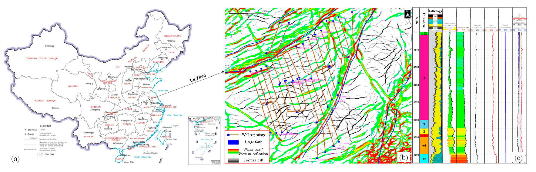
Figure 1: The geographical location (a), fracture development characteristics (b), lithology profile and rock mechanics characteristics (c) of Lu203.
In this study, a true triaxial multi-physics large-scale physical simulation experiment system was developed and constructed independently to carry out a hydraulic fracturing physical simulation experiment. The system is mainly composed of a fracturing fluid injection system, a triaxial compression loading system, a monitoring system and a triaxial loading chamber. The overall structure is shown in Fig. 2. The X-Y-Z three-direction loading plate provides power loading through the oil cylinder, and the maximum loading stress can reach 40 MPa and the maximum fracturing pressure can reach 120 MPa. Therefore, the loading method adopted by the true triaxial test instrument can better simulate the formation stress state through triaxial compression. The maximum size of the sample that can be placed in the chamber is 400 mm × 400 mm × 400 mm. To mitigate the effects of surface imperfections, 0.5 mm neoprene pads were placed between specimen faces and loading platens. The real-time monitoring system of flow and pressure is composed of a flow acquisition instrument and a computer data acquisition and control instrument, which can realize real-time monitoring and recording of the pressure, displacement and volume of pumping.
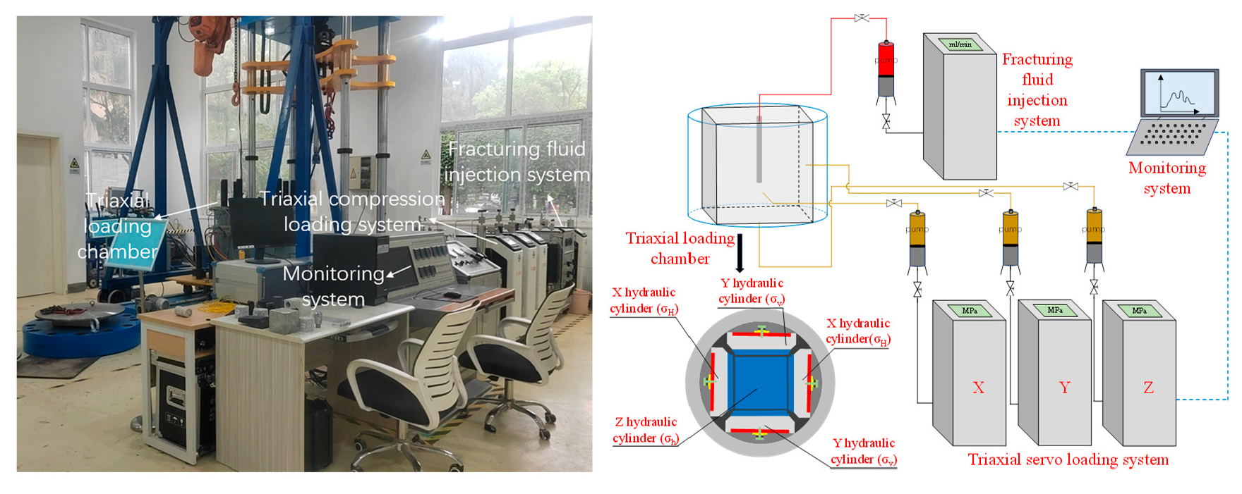
Figure 2: True triaxial multi-physics large-scale physical simulation experiment system.
2.3 Instantaneous Fracturing Mechanism of Flow Pressurization and Sample Preparation
2.3.1 Instantaneous Fracturing Mechanism of Constant Flow Pressurization
Under the constant flow injection mode, before the hydraulic fracture starts to initiate, its length is 0, and the fluid pressure in the wellbore is constant at a certain time. The fluid pressure in the wellbore gradually increases with time. The high-pressure fluid induces a high-stress area around the wellbore. The mineral particles near the wellbore have different deformations due to their different stiffness, which forms stress concentration in local areas, resulting in the primary weak surface cracking and generating hydraulic fractures [19]. The high-pressure fluid accumulated in the wellbore immediately diffuses into the fracture to drive the hydraulic fracture’s further propagation, causing the sample’s instantaneous breakdown. In this process, due to the fluid flow in the main fracture, the fluid pressure presents a gradient distribution of non-uniform pressure from the injection point to the fracture tip [20]. Therefore, this study employs constant-flow injection of fracturing fluid to investigate the 3D propagation characteristics of hydraulic fractures and their corresponding fracturing fluid pressure response characteristics under complex geomechanical settings.
Considering that the rock strength of outcrop samples is difficult to meet the requirements of deep rock samples, the strong heterogeneity affects the stability and accuracy of the experimental results, and it is difficult to obtain large physical model experimental samples underground, we adopted indoor pouring samples for the experiment. Combined with the geological characteristics of the reservoir in southern Sichuan, and based on the similarity criterion [21], a suitable similarity scale was selected. The sample was made of 425 type cement, 80 mesh fine sand and water, with a mass ratio of 2:1:0.1 (cement: fine sand: water), and the sample size was 400 mm × 400 mm × 400 mm. At the same time, in order to characterize the stratification characteristics of the sample, we adopted the method of stratification to make the sample. The sample was divided into seven layers, and after each layer was made, we waited half an hour before making the next layer to ensure that there was a certain weak cementation between the layers, but the strength of the weak cementation was not particularly low, so as to ensure that our research results would not be affected. The simulated wellbore has an inner diameter of 6 mm, an outer diameter of 16 mm, a wall thickness of 5 mm, an overall length of 360 mm, a cluster of four holes, a hole size of 2 mm, and an angle of 90° between the holes. In order to ensure the brittle-plastic contrast of the sample, a plasticizer was added to the biased ductile sample to improve the ductile characteristics of the sample. In addition, based on the raw material of the artificial sample, a cylindrical core was prepared for a pseudo-triaxial test to test the brittleness and ductility characteristics of the artificial sample (Fig. 3). This is consistent with the classical failure curve of brittle and ductile samples. The elastic modulus of the test sample is 16 GPa, Poisson’s ratio is 0.2, and the uniaxial compressive strength is 32 MPa. The specific test parameters are shown in Table 1. At the same time, the influence of natural fractures on the initiation and propagation of hydraulic fractures is studied by placing pre-arranged fractures on one side of the wellbore and not on the symmetrical side of the wellbore. The angle between the fracture and the wellbore on one side with the preset fracture is 45° and the distance from the perforation hole is 5 cm, and the fracture size is 5 cm × 10 cm (Fig. 4).
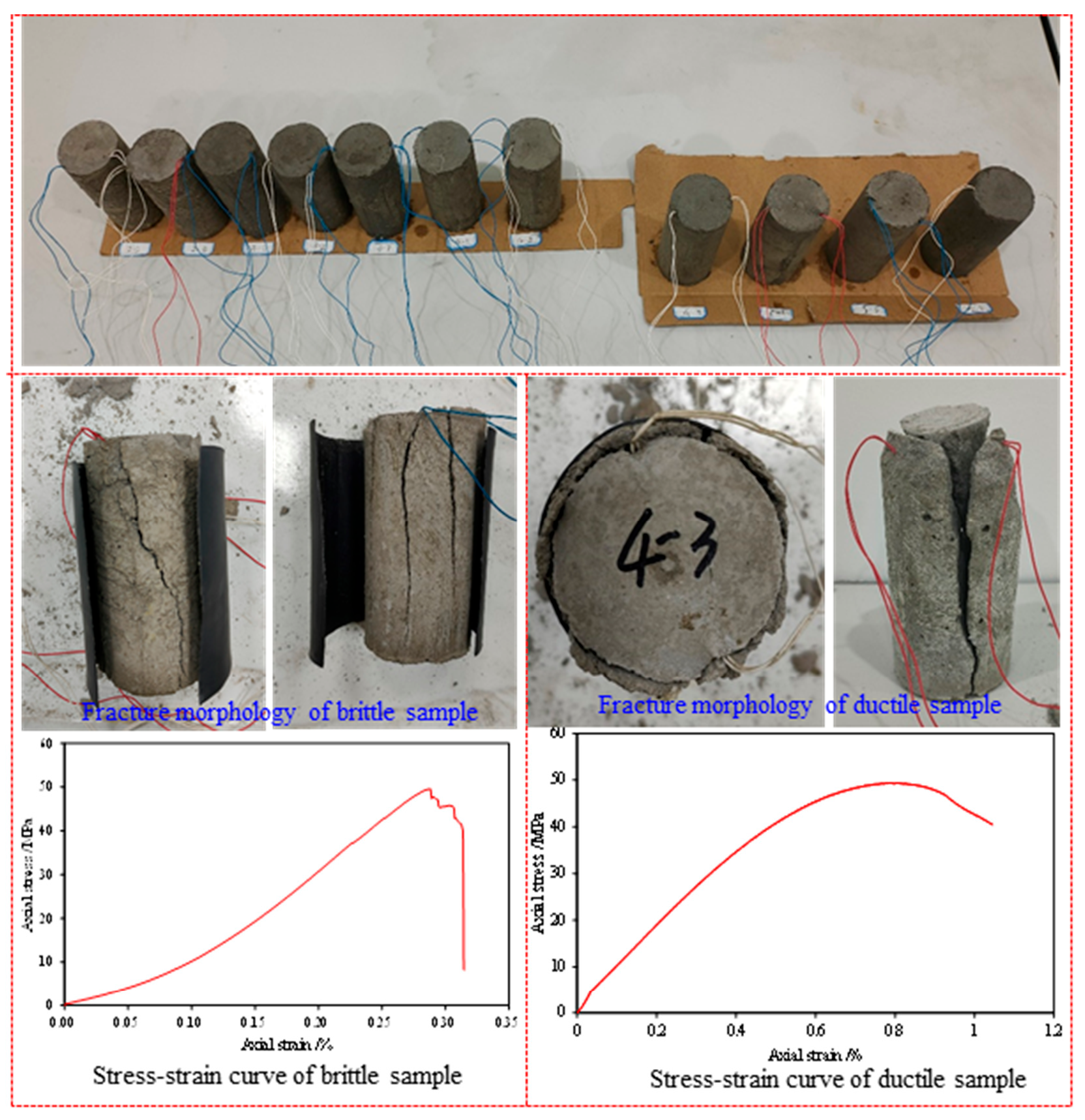
Figure 3: The test results of pseudo-triaxial compression of brittle and ductile samples.
Table 1: The mechanical parameters of brittle and ductility samples.
| No. | Confining Pressure (MPa) | Young’s Modulus (GPa) | Poisson’s ratio | Compressive Strength (MPa) | Brittleness or Ductility |
|---|---|---|---|---|---|
| 1 | 25 | 6.24 | 0.235 | 52.6 | brittleness |
| 2 | 25 | 6.15 | 0.239 | 55.1 | brittleness |
| 3 | 25 | 5.21 | 0.224 | 53.7 | brittleness |
| 4 | 25 | 6.31 | 0.231 | 54.8 | brittleness |
| 5 | 25 | 6.28 | 0.241 | 55.6 | brittleness |
| 6 | 25 | 5.94 | 0.229 | 53.2 | brittleness |
| 7 | 25 | 5.81 | 0.234 | 54.9 | brittleness |
| 8 | 25 | 4.31 | 0.302 | 48.2 | ductility |
| 9 | 25 | 5.47 | 0.287 | 47.9 | ductility |
| 10 | 25 | 4.12 | 0.292 | 45.7 | ductility |
| 11 | 25 | 4.58 | 0.311 | 46.5 | ductility |
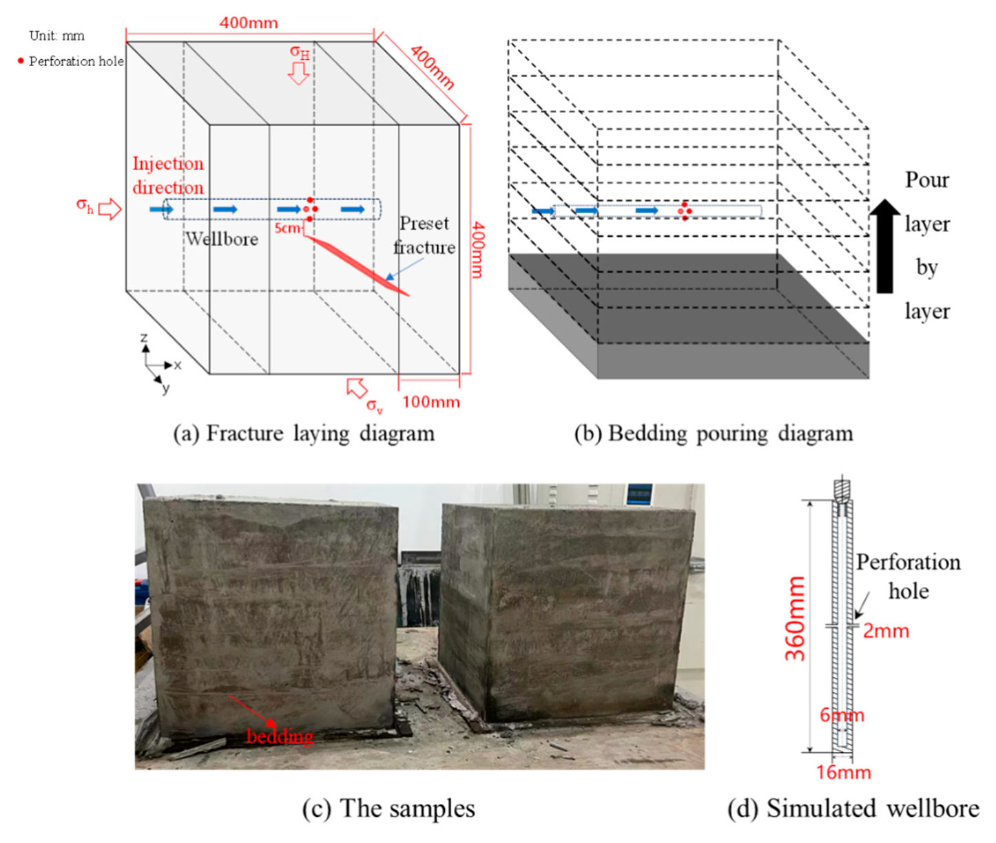
Figure 4: Schematic diagram of the artificial samples and the simulated wellbore.
2.4 Experimental Process and Scheme
Hydraulic fractures typically propagate along the maximum principal stress direction. However, in shale formations characterized by complex mineral compositions, abundant natural fractures, and pronounced structural anisotropy, hydraulic fractures interact with the matrix, natural fractures, and bedding planes through behaviors such as penetration, capture, diversion, and offset. Among these, the geometric configuration of discontinuous interfaces and their physico-mechanical properties exert the most significant influence [22,23]. Therefore, this study investigates hydraulic fracture propagation morphology in heterogeneous shale reservoirs under varying stress anisotropy, natural fracture distributions, and brittle-ductile properties. In this study, a total of 9 samples in 3 groups were simulated and compared in fracturing experiments, all of which used water with red tracer as fracturing fluid. The minimum horizontal principal stress (σh) is applied along the axis of the wellbore (X direction), the maximum horizontal principal stress (σH) is applied perpendicular to the plane of the preset fracture (Z direction), and the intermediate principal stress (σv) is applied parallel to the plane of the preset fracture (Y direction). The influence of stress difference on hydraulic fracture was investigated by changing the value of the three-way principal stress. Put the fully consolidated sample into the true triaxial experimental instrument kettle, connect the liquid injection pipe and install the pressure plate. In order to ensure the uniform force on each surface of the sample, the pressure in the y and z directions is applied first, and then the pressure is applied in the x direction until the three-way confining pressure rises to a predetermined value. Two values are used for the stress difference, among which 13.5 MPa is the average value of the stress difference in the LU203 block, and 18 MPa is about the highest value. After that, the fracturing fluid was injected into the sample at a constant rate of 15 mL/min, and the pumping pressure curve was followed in real time until the end of the experiment. The damage morphology of the sample after the test is shown in Fig. 5, and the specific parameters are shown in Table 2.
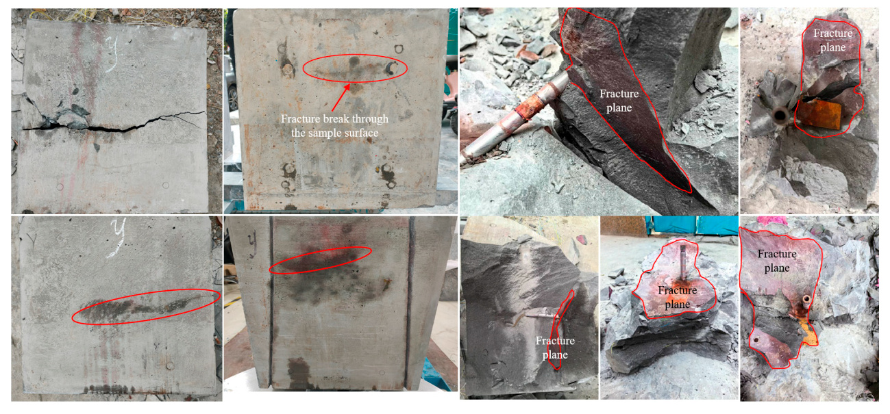
Figure 5: Fracture morphology of samples after fracturing.
Table 2: Parameters of fracturing simulation experiment.
| Sample Number | Sample Size/mm3 | Brittleness or Ductility | Triaxial Pressure/MPa | Flow Rate/(mL·min−1) | |
|---|---|---|---|---|---|
| 1-1 | 400 | Brittleness | | 13.5 | 15 |
| 1-2 | 400 | Brittleness | 13.5 | 15 | |
| 1-3 | 400 | Brittleness | 13.5 | 15 | |
| 2-1 | 400 | Brittleness | | 18 | 15 |
| 2-2 | 400 | Brittleness | | 18 | 15 |
| 2-3 | 400 | Brittleness | | 18 | 15 |
| 3-1 | 400 | Ductility | | 13.5 | 15 |
| 3-2 | 400 | Ductility | | 13.5 | 15 |
| 3-3 | 400 | Ductility | | 13.5 | 15 |
3.1 Compressive Characteristics of Brittle Sample
As shown in Fig. 6, the fracture geometry morphology of brittle/ductile samples was reconstructed based on the fracture plane morphology of fractured samples. On the whole, the three samples all formed a vertical main hydraulic fracture, and when they propagated to the preset natural fracture plane, they all turned and activated the natural fracture, and the vertical propagation was limited, making the natural fracture channel an advantageous propagation path. Then the hydraulic fracture gradually turns to the direction of maximum horizontal principal stress and breaks through to the surface of the sample. That means when the horizontal stress difference is high, it is difficult for fractures to contain pressure, and the fracturing fluid directly passes through the natural fractures with weak bonding strength to form a single main fracture until it reaches the model boundary through the sample, and the fracture surface is flatter.
The injection pressure-time curve can be divided into four stages: initial compression stage, rapid compression stage, post-peak pressure drop stage, and post-peak pressure stabilization stage. Additionally, the fluid injection pressure characteristic curve reveals: Following completion of fracturing fluid filling in high-pressure pipelines and wellbores, the pressure required to drive fluid begins to increase rapidly, reaching the specimen’s breakdown pressure at approximately 13.5 min. Under a stress difference of 13.5 MPa, with continued fracturing fluid pumping, specimens 1-1, 1-2, and 1-3 exhibited initial (peak) breakdown pressures of 14.09, 15.15, and 15.45 MPa, respectively. During the fracture propagation stage, all three specimens maintained fluid pressures around 12 MPa. Concurrently, throughout subsequent fracturing fluid injection, multiple pressure peaks occurred across all specimens, with the injection pressure curve displaying frequent fluctuations. This reflects multiple fracturing events induced by fluid pressure, involving initiation and propagation of new fractures, or post-communication between hydraulic fractures and natural fractures where fracturing fluid intrudes into natural fracture systems. This intrusion alters net fluid pressure within the fracture network, consequently causing frequent fluctuations in the injection pressure curve.
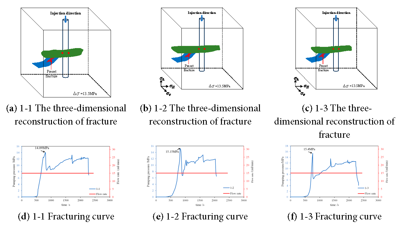
Figure 6: Fracture geometry morphology and fracture curve of brittle sample after fracturing.
3.2 Compressive Characteristics of Ductile Sample
The ductile characteristics of rock also have some influence on fracture propagation. Fig. 7 shows the three-dimensional reconfiguration of the ductile sample after pressure and the pumping pressure curve. From the three-dimensional reconfiguration, it can be found that the vertical main hydraulic fracture stops vertical propagation after activating the natural fracture through communication, but turns directly to the natural fracture and continues to propagate and expand as an extension path. After reaching the bottom of the natural fracture, it turns toward the direction of the maximum horizontal principal stress and continues to expand until it breaks through the specimen surface.
Simultaneously, the fluid injection characteristic curve indicates that all three specimens reached breakdown pressure at approximately 22 min. Specimens 3-1, 3-2, and 3-3 exhibited peak breakdown pressures of approximately 14.11, 14.93, and 14.4 MPa, respectively. Notably, Specimen 3-2 displayed two distinct breakdown pressure peaks, indicating significant secondary fracture generation, consistent with post-fracturing observations of fracture surface coverage within the specimens. The propagation pressure for all three specimens was distributed around 10 MPa.
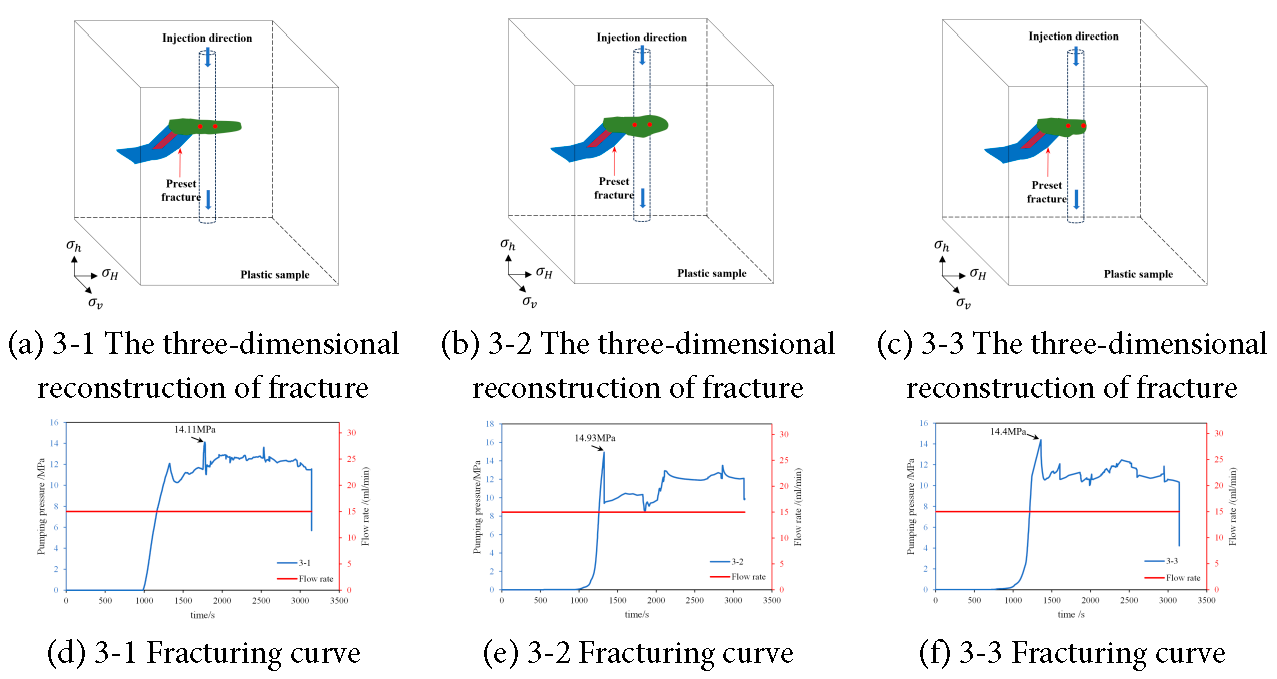
Figure 7: Fracture geometry morphology and fracture curve of ductile sample after fracturing.
3.3 Compressive Characteristics of Samples in High Stress Difference Environment
Beyond the inherent rock brittleness or ductility, the stress difference also plays a crucial role in fracture propagation, as discussed below. Fig. 8 shows the fracture geometry morphology and fracture curve of the samples with high stress difference (18 MPa) after fracturing. The three-dimensional reconstruction of the fracture shows that only one straight fracture appears in the direction of the maximum horizontal principal stress of the three samples. Because the horizontal stress difference is too high, the natural fracture is only slightly activated, only a small amount of fracturing fluid enters, and it does not become a dominant channel. The hydraulic fracture still propagates along the direction of the maximum horizontal principal stress until it breaks through to the sample surface.
The fracturing fluid pressure curve indicates that the specimen reached breakdown pressure at approximately 6.8 min, with peak values of 25.33, 24.6, and 23.76 MPa, respectively. At this point, initial fracture initiation occurred under fluid pressure. Subsequently, fluid pressure within the fracture plummeted to approximately 10 MPa. With continued pumping of fracturing fluid, the fluid pressure curve stabilized without significant fluctuations, maintaining around 15 MPa during the fracture propagation stage.
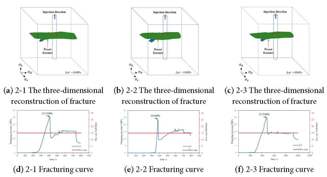
Figure 8: Fracture geometry morphology and fracture curve of the samples in a high stress environment.
Since the experiments in this work have proved a uniformity for fracture shape and injection curve, the schematic shape of the HF-NF intersection can be drawn based on the results. To evaluate the influence of three different typical geomechanical conditions, the schematic fracture morphology of HF-NF intersection behavior and the corresponding pumping pressure over injection time are compared, as shown in Fig. 9.
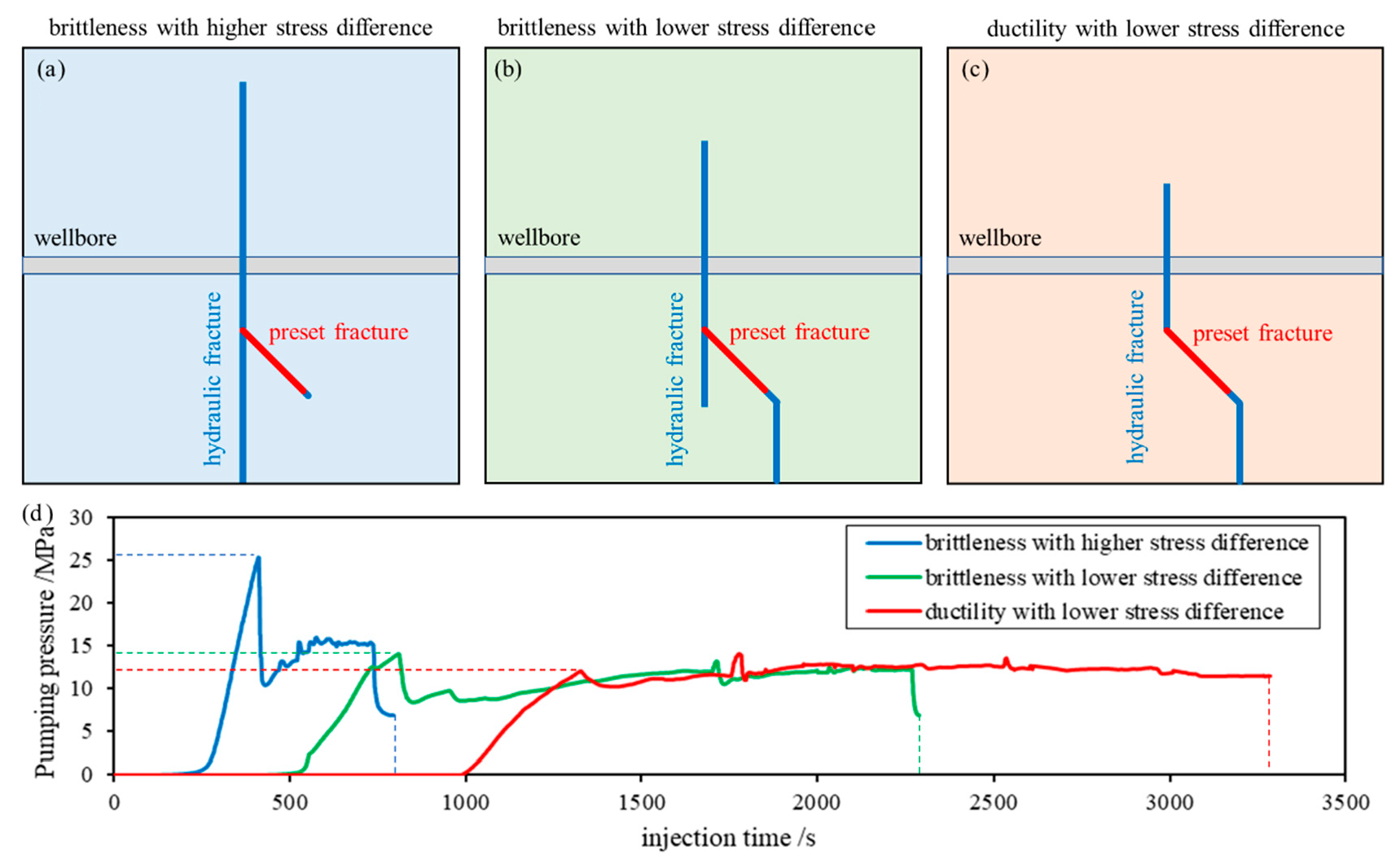
Figure 9: Behavior of hydraulic fracture interaction with natural fracture among different geomechanical conditions. (a) schematic fracture morphology of intersection behavior under brittleness with higher stress difference; (b) schematic fracture morphology of intersection behavior under brittleness with lower stress difference; (c) schematic fracture morphology of intersection behavior under ductility with lower stress; (d) pumping pressure responding among different geomechanical conditions.
- (1)Impact of ductility
For brittle shale (especially in middle-shallow depth) with a small approach angle, fluid-driven hydraulic fractures under fluid pressure can trigger natural fracture activation while simultaneously extending along the horizontal minimum stress direction, facilitating complex fracture network formation. For deep plastic shale, natural fractures may be activated, but hydraulic fracture propagation remains entirely constrained by natural fracture networks under fluid pressure, generating only a single dominant path (Fig. 9b,c). While horizontal stress difference and natural fracture parameters govern fracture network complexity, deep shale ductility dominates fluid-driven fracture propagation behavior, overriding these factors.
Moreover, the fracturing fluid pressure characteristics reveal that greater fluid volumes are required for ductile sample initiation due to delayed breakdown pressure timing (Fig. 9d). This indicates that overcoming deep shale ductility demands a significantly increased injection intensity (fluid volume per section meter) to achieve perforation results comparable to middle-shallow layers through enhanced fluid energy delivery.
- (2)Impact of stress difference
High stress difference promotes simplified hydraulic fracture geometry with minimal natural fracture engagement by fluid flow, even at small approach angles (Fig. 9a). Fig. 9d demonstrates that elevated stress differences require higher breakdown pressures, indicating increased fluid pressure demands on wellbore integrity. Propagation to geometric boundaries under high stress difference requires only approximately one-third of the time of low-stress conditions, reducing fluid energy dissipation and improving operational efficiency. Thus, high stress differences simultaneously reduce fracture network complexity under equivalent fluid injection conditions and shorten treatment duration. High-density and multi-cluster fracturing may enhance efficiency by optimizing fluid distribution. Note: While this Experimental analysis used absolute stress difference, future work will implement stress difference coefficients.
- (3)Impact of natural fractures
Natural fractures significantly alter fluid-driven hydraulic fracture propagation [24]. When hydraulic fractures encounter natural fractures, the approach angle and stress differences jointly control the fluid diversion behavior [25]. Fig. 6 demonstrates that under identical stress conditions, both elastic and ductile samples (with/without preset fractures) exhibit asymmetric propagation. This occurs because fracturing fluid preferentially enters low-resistance pathways along weaker prefabricated fractures, generating fluid-dominated “slope-type” fracture surfaces until reaching model boundaries. For deep shale, the presence of natural fractures alone cannot ensure efficient network formation; their fluid-conducting potential is constrained by the rock’s ductility and the ambient stress state.
These experimental findings enable actionable optimizations for shale operations in the Sichuan Basin, particularly for perforation clusters and fluid injection parameters.
- (1)Compared to brittle shale at mid-to-shallow depths with small approach angles, hydraulic fractures in deep ductile shale are primarily governed by natural fractures, resulting in a single propagation path. To counteract the effects of ductility, injection intensity (fluid volume per meter) must be significantly increased to achieve stimulation results comparable to those in shallower formations. In deep shale, pronounced ductility may be the dominant factor limiting fracture network complexity.
- (2)High stress differences significantly reduce treatment time, with fractures reaching geometric boundaries in only one-third of the time required under low-stress conditions. Consequently, elevated stress differences lead to both reduced fracture complexity and shorter operational durations in field applications.
- (3)Under higher stress difference conditions, elastic rock samples subjected to fluid injection exhibit simple and planar hydraulic fracture geometries, with natural fractures experiencing minimal dilation under the applied fluid pressure, achieved within a very short injection duration. Conversely, lower stress difference conditions promote fluid-driven mechanisms conducive to the formation of permeable complex fracture networks. Finally, for typical deep shale fracturing, a larger injection fluid volume as well as high-density, multi-cluster fracturing techniques are recommended.
Acknowledgement:
Funding Statement: This work was funded by the National Natural Science Foundation of China (Nos. 52204005, 52192622, U20A20265), the Sichuan Science Fund for Young Scholars (23NSFSC4652).
Author Contributions: Bo Zeng: Conceptualization, Methodology, writing—original draft, writing—review & editing; Junfeng Li: Writing—review & editing, investigation; Liqing Chen: Visualization, resources; Qiyong Gou: Methodology, supervision; Hao Luo: Methodology, supervision; Haiyan Zhu: Project administration, funding acquisition; Xuanhe Tang: Formal analysis, data curation, writing—original draft. All authors reviewed and approved the final version of the manuscript.
Availability of Data and Materials: The data that support the findings of this study are available from the corresponding author upon reasonable request.
Ethics Approval: Not applicable.
Conflicts of Interest: The authors declare no conflicts of interest.
References
1. Zou CN , Zhao Q , Cong LZ , Wang HY , Shi ZS , Wu J , et al. Development progress, potential and prospect of shale gas in China. Nat Gas Ind. 2021; 41( 1): 1– 14. (In Chinese). [Google Scholar]
2. Wang J , Guo QL , Zhao CL , Wang YM , Yu JD , Liu Z , et al. Potentials and prospects of shale oil-gas resources in major basins of China. Acta Petrolei Sin. 2023; 44( 12): 2033– 44. (In Chinese). [Google Scholar]
3. Huang L , Liao X , Fan M , Wu S , Tan P , Yang L . Experimental and numerical simulation technique for hydraulic fracturing of shale formations. Adv Geo-Energy Res. 2024; 13( 2): 83– 8. doi:10.46690/ager.2024.08.02. [Google Scholar] [CrossRef]
4. Yu J , Zhang Q , Jia C , Lei M , Zhao C , Pang R , et al. Experimental and DEM simulations of the mechanical properties of rock under freeze–thaw cycles. Cold Reg Sci Technol. 2023; 211: 103866. doi:10.1016/j.coldregions.2023.103866. [Google Scholar] [CrossRef]
5. Renshaw CE , Pollard DD . An experimentally verified criterion for propagation across unbounded frictional interfaces in brittle, linear elastic materials. Int J Rock Mech Min Sci Geomech Abstr. 1995; 32( 3): 237– 49. doi:10.1016/0148-9062(94)00037-4. [Google Scholar] [CrossRef]
6. Zheng Y , Jia C , Lei M , Huang J , Shi C . Investigation of the constitutive damage model of rock under the coupled effect of freeze–thaw cycles and loading. Rock Mech Rock Eng. 2024; 57( 3): 1861– 79. doi:10.1007/s00603-023-03627-2. [Google Scholar] [CrossRef]
7. Heidari Moghaddam R , Golshani A . Experimental study on fracture propagation in anisotropy rock under cyclic hydraulic fracturing. Eng Fract Mech. 2024; 295: 109775. doi:10.1016/j.engfracmech.2023.109775. [Google Scholar] [CrossRef]
8. Beugelsdijk LJL , De Pater CJ , Sato K . Experimental hydraulic fracture propagation in multi-fractured medium. In: Proceedings of the SPE Asia Pacific conference on integrated modelling for asset management; 2000 Apr 25–26; Yokohama, Japan. doi:10.2118/59419-MS. [Google Scholar] [CrossRef]
9. Peacock DCP , Mann A . Controls on fracturing in carbonate rocks. In: Proceedings of the SPE Middle East Oil and Gas Show and Conference; 2005 Mar 12–15; Manama, Bahrain. doi:10.2523/92980-MS. [Google Scholar] [CrossRef]
10. Jiang CB , Yang YH , Liu HH , Guo JQ , Fu YL , Wu JY . Study on influence of natural fractures on initiaition and propagation of hydraulic fracturing coal. Coal Sci Technol. 2024; 52( 5): 92– 101. (In Chinese). [Google Scholar]
11. Warpinski NR , Lorenz JC , Branagan PT , Myal FR , Gall BL . Examination of a cored hydraulic fracture in a deep gas well. SPE Prod Facil. 1993; 8( 3): 150– 8. doi:10.2118/22876-pa. [Google Scholar] [CrossRef]
12. Fu H , Huang L , Hou B , Weng D , Guan B , Zhong T , et al. Experimental and numerical investigation on interaction mechanism between hydraulic fracture and natural fracture. Rock Mech Rock Eng. 2024; 57( 12): 10571– 82. doi:10.1007/s00603-024-04101-3. [Google Scholar] [CrossRef]
13. Warpinski NR , Teufel LW . Influence of geologic discontinuities on hydraulic fracture propagation (includes associated papers 17011 and 17074). J Petrol Technol. 1987; 39( 2): 209– 20. doi:10.2118/13224-pa. [Google Scholar] [CrossRef]
14. Jeffrey RG , Bunger AP , Lecampion B , Zhang X , Chen ZR , van As A , et al. Measuring hydraulic fracture growth in naturally fractured rock. In: Proceedings of the SPE Annual Technical Conference and Exhibition; 2009 Oct 4–7; New Orleans, Louisiana. doi:10.2118/124919-ms. [Google Scholar] [CrossRef]
15. Yu S , Ren X , Zhang J . Modeling the rock frost cracking processes using an improved ice–Stress–Damage coupling method. Theor Appl Fract Mech. 2024; 131: 104421. doi:10.1016/j.tafmec.2024.104421. [Google Scholar] [CrossRef]
16. Jeffrey RG , Weber CR , Vlahovic W , Enever JR . Hydraulic fracturing experiments in the great northern coal seam. In: Proceedings of the SPE Asia Pacific Oil and Gas Conference; 1994 Nov 7–10; Melbourne, Australia. doi:10.2118/28779-ms. [Google Scholar] [CrossRef]
17. Rueda J , Mejia C , Quevedo R , Roehl D . Impacts of natural fractures on hydraulic fracturing treatment in all asymptotic propagation regimes. Comput Meth Appl Mech Eng. 2020; 371: 113296. doi:10.1016/j.cma.2020.113296. [Google Scholar] [CrossRef]
18. Barbosa LG , Cleto PR , Maedo MA , Camargo M , Rodrigues EA , Manzoli OL . Simulation of the natural fractures influence on hydraulic fractures propagation using high aspect ratio interface elements. Comput Geotech. 2025; 179: 107026. doi:10.1016/j.compgeo.2024.107026. [Google Scholar] [CrossRef]
19. Fallahzadeh SH , Shadizadeh SR , Pourafshary P . Dealing with the challenges of hydraulic fracture initiation in deviated-cased perforated boreholes. In: Proceedings of the Trinidad and Tobago Energy Resources Conference; 2010 Jun 27–30; Port of Spain, Trinidad. doi:10.2118/132797-ms. [Google Scholar] [CrossRef]
20. Wei M , Dai F , Ji Y , Wu W . Effect of fluid pressure gradient on the factor of safety in rock stability analysis. Eng Geol. 2021; 294: 106346. doi:10.1016/j.enggeo.2021.106346. [Google Scholar] [CrossRef]
21. Huang X , Huang J . Study on the proportion of similar materials in physical simulation of low strength and high brittleness rockfall. J Geol Hazards Environ Preserv. 2022; 33( 2): 21– 6. (In Chinese). [Google Scholar]
22. Sarmadi N , Harrison M , Mousavi Nezhad M , Fisher QJ . Hydraulic fracture propagation in layered heterogeneous rocks with spatially non-Gaussian random hydromechanical features. Rock Mech Rock Eng. 2024; 57( 10): 8117– 40. doi:10.1007/s00603-024-03954-y. [Google Scholar] [CrossRef]
23. Tang XH , Zhu HY , Li KD . A FEM-DFN-based complex fracture staggered propagation model for hydralic fracturing of shale gas reservoirs. Nat Gas Ind. 2023; 43( 1): 162– 76. (In Chinese). [Google Scholar]
24. Gao Q , Zhou Z , Han Y , Zhou D , Ghassemi A , Sun Q . Study on hydraulic fracture propagation under the influence of natural fractures in fractured reservoirs. Environ Earth Sci. 2025; 84( 15): 425. doi:10.1007/s12665-025-12428-5. [Google Scholar] [CrossRef]
25. Blanton TL . Propagation of hydraulically and dynamically induced fractures in naturally fractured reservoirs. In: Proceedings of the SPE Unconventional Gas Technology Symposium; 1986 May 18-21. Louisville, Kentucky. doi:10.2118/15261-ms. [Google Scholar] [CrossRef]
Cite This Article
 Copyright © 2026 The Author(s). Published by Tech Science Press.
This work is licensed under a Creative Commons Attribution 4.0 International License , which permits unrestricted use, distribution, and reproduction in any medium, provided the original work is properly cited.
 Downloads
 Citation Tools