
 Submit a Paper
 Propose a Special lssue
 Open Access
REVIEW

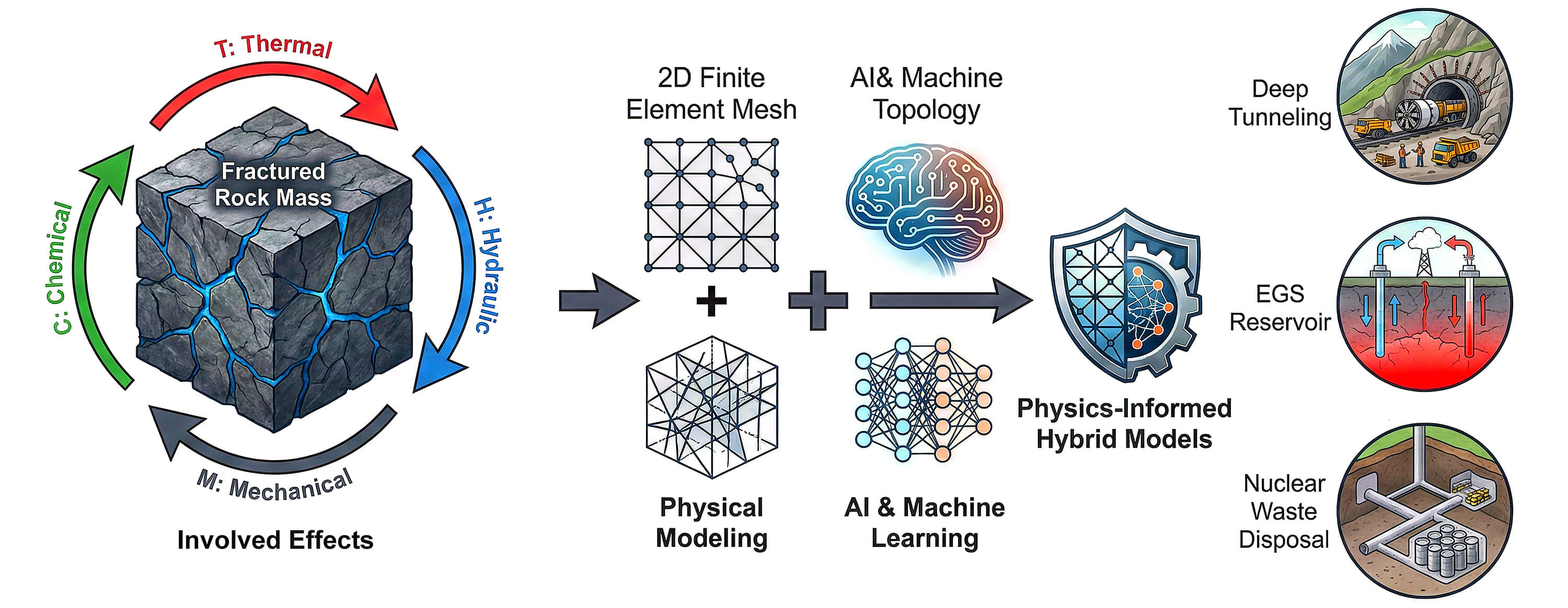
Fluid Flow in Fractured Rocks: From Multiphysics Paradigms to AI-Driven Predictive Modeling
School of Civil Engineering and Architecture, Xi’an University of Technology, Xi’an, China
* Corresponding Author: Yi Xue. Email:
(This article belongs to the Special Issue: Fluid Dynamics and Multiphysical Coupling in Rock and Porous Media: Advances in Experimental and Computational Modeling)
Fluid Dynamics & Materials Processing 2026, 22(2), 2 https://doi.org/10.32604/fdmp.2026.075809
Received 09 November 2025; Accepted 12 February 2026; Issue published 04 March 2026
 View Full Text
 Download PDF
Abstract
Fluid flow through fractured rock masses is a key process controlling the safety and performance of deep geoengineering systems, shaped by the complex interactions of thermal, hydraulic, mechanical and chemical (THMC) fields. This paper presents a systematic review of this subject with special emphasis on the multi-physics governing it. First, we elucidate the interdependent mechanisms and governing equations, highlighting the nonlinear, path-dependent, and evolving nature of the relationship between stress and permeability. Next, mainstream modeling approaches, including equivalent continuum, discrete fracture network (DFN), and dual-porosity/dual-permeability methods, are critically evaluated, and a strategy for model selection based on project scale and geological context is proposed accordingly. Moreover, experimental insights from single-fracture and triaxial flow studies are synthesized, revealing how effective stress, shear displacement, and fracture roughness control permeability evolution. In particular, the practical significance of THMC coupling is demonstrated through case studies on nuclear waste disposal, Enhanced Geothermal Systems, and tunneling projects. The review further explores AI- and machine learning-driven innovations, particularly physics-informed neural networks and hybrid modeling, which address limitations in computational efficiency, data scarcity, and physical consistency. Finally, persistent challenges, including multi-scale coupling, parameter uncertainty, and complex fracture network representation are identified and critically discussed while paying attention to future developments.Graphic Abstract
Keywords
1.1 Research Background, Significance, and Core Challenges
Fractured rock masses, dissected by discontinuous structural planes such as joints, faults, and bedding planes, exhibit hydro-mechanical behaviors fundamentally distinct from homogeneous porous media. Their pronounced spatial heterogeneity, geometric discontinuity, and permeability anisotropy govern fluid transport and critically influence the stability and performance of geotechnical and energy system [1]. Accurately characterizing and predicting seepage in such media remains a persistent challenge in geoscience and rock engineering.
In practice, seepage processes often dictate the success or failure of major subsurface projects. For example, in deep tunnels and underground caverns, coupled seepage–stress effects can trigger large deformations or catastrophic water inrush [2]. Similarly, in EGS, unconventional hydrocarbon recovery, and CO2 sequestration, effective reservoir management hinges on understanding how THMC processes dynamically alter fracture networks and their permeability evolution [3].
Despite extensive research on individual aspects—ranging from conceptual modeling to numerical simulation—a comprehensive, up-to-date synthesis that integrates theoretical frameworks, experimental insights, numerical advances, and emerging AI-driven paradigms is still lacking. This review aims to bridge these gaps by: (i) systematically categorizing seepage models; (ii) evaluating experimental scale effects and THMC coupling mechanisms; (iii) comparing mainstream numerical methods; and (iv) critically assessing the role of AI, particularly PINNs. The paper is organized as follows: Section 2 presents the fundamental principles and governing equations of THMC coupling. Section 3 reviews modeling paradigms and numerical methods for seepage. Section 4 synthesizes experimental findings on seepage characteristics. Section 5 demonstrates practical relevance through engineering case studies. Section 6 explores the integration of AI and ML in subsurface flow modeling. Section 7 discusses persistent challenges and outlines future research directions. Finally, Section 8 concludes the review with key takeaways and a forward-looking perspective.
The fundamental challenge underlying these engineering practices lies in the fact that fractures—the dominant pathways controlling fluid flow—exhibit highly random and nonlinear geometric configurations, spatial distributions, and mechanical behaviors [4,5,6]. This renders the traditional equivalent continuum theory, which relies on the assumption of a “Representative Elementary Volume (REV) [7] “invalid in many practical scenarios. Crucially, the relationship between fracture permeability and effective stress is not merely linear; instead, it displays strong nonlinearity, hysteresis, and path dependence [8]. This implies that the hydraulic properties of the rock mass evolve along distinct trajectories during loading and unloading cycles—a complex behavior that cannot be captured by static or linear models. Consequently, advanced multi-field coupling theories and dynamic numerical simulation methods are essential for in-depth investigation [9].
1.2 Structure and Research Objectives of This Paper
This review aims to provide a systematic and critical synthesis of the current state of research on fluid flow in fractured rock masses and the underlying THMC multi-field coupling mechanisms. Its primary objective is not merely to catalog existing achievements, but rather to reveal the consensus, controversies, and emerging frontiers in the field by deeply analyzing the intrinsic connections and contradictions among theoretical models, experimental findings, numerical methods, and engineering practices. In doing so, it seeks to offer a robust theoretical reference and methodological guidance for future fundamental research and engineering applications.
To achieve this objective, the paper follows a clear and coherent logical structure: First, it begins with fundamental principles, articulating the physical mechanisms of THMC coupling that govern fractured rock behavior and their mathematical formulations (Section 2). Next, it systematically reviews prevailing theoretical modeling paradigms—such as ECM and DFN—alongside numerical implementation methods—including the Finite Element Method (FEM), Discrete Element Method (DEM), and Lattice Boltzmann Method (LBM)—and provides a comparative analysis of their applicability and limitations (Section 3). Building on this foundation, the discussion turns to experimental research, synthesizing key findings from single-fracture and triaxial seepage experiments to establish a robust empirical basis for theoretical models (Section 4). Subsequently, the paper examines three representative high-stakes engineering case studies—geological disposal of nuclear waste, EGS, and tunneling projects—to demonstrate how THMC coupling theory addresses cutting-edge, high-risk engineering challenges (Section 5). Following this, it explores how AI and ML are emerging as transformative forces that are reshaping research paradigms in the field, analyzing their synergies and complementarities with traditional approaches (Section 6). Finally, the paper confronts current bottlenecks and outlines future directions, offering forward-looking perspectives on critical issues such as multi-scale modeling, parameter uncertainty, and representation of complex fracture networks (Section 7).
2 Fundamental Principles and Governing Equations of THMC Coupling
2.1 Interlocking Mechanisms of THMC Coupling
The complete THMC behavior of fractured rock masses is fundamentally an interlocked system in which multiple physical fields are tightly intertwined and mutually driven [10]. Its defining characteristic lies not in the independent action of individual fields, but in the causal chains and dynamic feedback loops established among them through well-defined physical laws [11]. A perturbation in any one field inevitably propagates and amplifies through coupling mechanisms, ultimately reshaping the state of the entire system [12]. This intrinsic interdependence necessitates that accurate prediction of fractured rock behavior move beyond the simplified paradigm of single-field analysis and instead adopt a unified, fully coupled theoretical framework.
Within this framework, the four physical fields—thermal (T), hydraulic (H), mechanical (M), and chemical (C)—are interconnected through a series of core coupling mechanisms [13]:
- Mechanical-Hydraulic Coupling: This is the most fundamental and direct coupling mechanism. Changes in the mechanical field—such as stress redistribution caused by excavation or fluid injection—directly alter the physical aperture and connectivity of fractures, thereby drastically modulating the permeability and fluid flux of the hydraulic field. Conversely, changes in the hydraulic field—such as increases or decreases in pore pressure—feed back into the mechanical field via the effective stress principle (
- Thermo-Mechanical Coupling: Changes in the thermal field induce thermal expansion or contraction of rock minerals, generating additional thermal stresses within the rock mass and consequently causing strain and displacement in the mechanical field. In EGS, the thermal stress induced by injecting cold fluid into hot rock is precisely the key physical mechanism that activates pre-existing fractures, promoting shear slip (hydraulic shearing) and thereby enhancing permeability [15].
- Hydro-Thermal Coupling: In fractured rock masses, heat transfer depends not only on thermal conduction through the rock matrix but, more significantly, on convective heat exchange by fluid flow. Key fluid properties—such as viscosity and density—are strong functions of temperature; consequently, the spatial distribution of the thermal field directly influences fluid flow patterns (hydraulic field), while fluid movement, in turn, redistributes heat and alters the thermal field itself [16]. This mutual modulation forms a complex, nonlinear feedback system.
- Chemo-Hydraulic Coupling: The chemical field primarily manifests through water–rock reactions. Dissolution or precipitation reactions between fluids and minerals microscopically alter the geometry of fracture walls—such as aperture and roughness—and even their mineralogical composition, thereby irreversibly modifying hydraulic conductivity. This process is particularly pronounced in reactive media such as bentonite buffer layers or shale, and represents a critical factor in assessing the long-term (millennia-scale) safety of nuclear waste repositories [17].
These coupling mechanisms do not operate in isolation; rather, they act synergistically and evolve dynamically. For example, in an EGS reservoir, a complete coupling cycle can be described as: hydraulic injection (H) → thermal gradient (T) → thermal stress (M) → fracture shear dilation (M–H) → increased permeability (H) → enhanced heat extraction efficiency (T) [18]. This chain clearly illustrates how an initial perturbation propagates through interlocked physical mechanisms, triggering a cascade of effects that ultimately reshape the system’s state. Fig. 1 further visualizes the core thermo-hydro-mechanical (THM) coupling paths in fractured rocks, explicitly depicting the dynamic feedback loops between hydraulic pressure, thermal gradient, and mechanical stress during fracture dilation and permeability evolution—directly echoing the EGS coupling cycle outlined above. It is precisely this highly nonlinear, path-dependent, and dynamically evolving nature that constitutes the fundamental challenge in studying seepage in fractured rock masses—and underscores the necessity of developing a comprehensive THMC coupling theory [19].
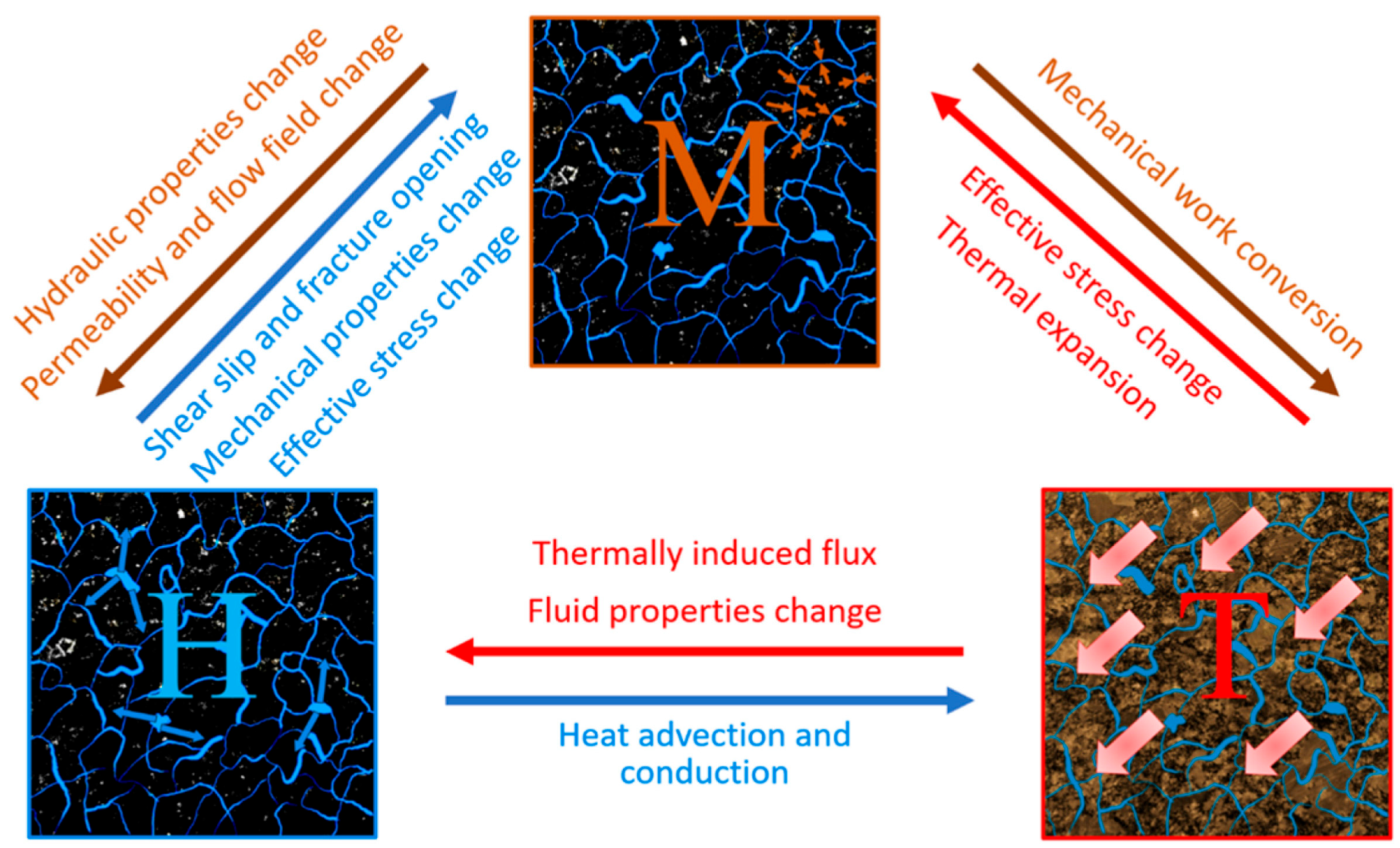
Figure 1: THM couplings in fractured rocks. Adapted with permission from Reference [20]. Copyright © 2025 Elsevier.
2.2 Governing Equations and Constitutive Relationships
The quantitative description of THMC multi-field coupled behavior in fractured rock masses relies on a set of interrelated partial differential equations. These equations respectively express the conservation laws governing the T, H, M, and C fields, and are unified into a single dynamical system through constitutive relationships [21]. This section systematically presents the core governing equations for each field and their key constitutive models, thereby establishing a solid theoretical foundation for subsequent numerical simulations and engineering analyses.
The mechanical response of rock masses is governed by the stress–strain constitutive relationship. For rock in an elastic or elastoplastic state, the relationship between the stress tensor
Within a multiphysics coupling framework, the principle of effective stress serves as the fundamental link between the mechanical and hydraulic fields. This principle states that the effective stress
Fluid flow in fractured rock masses typically follows Darcy’s law [24], which establishes a linear relationship between the fluid flux (Darcy velocity)
However, in high-velocity scenarios such as EGS or during hydraulic stimulation, inertial effects become significant, leading to non-Darcy flow behavior. Under these conditions—typically when the Reynolds number exceeds 1–10—the linear assumption of Darcy’s law breaks down. To account for this, the Forchheimer equation is widely adopted as a physically grounded extension:
In principle, the Navier-Stokes equations provide the most complete description of fluid motion at the fracture scale, resolving local velocity fields, turbulence, and boundary layer effects. However, their direct implementation in large-scale, fully coupled THMC models remains computationally prohibitive due to the need for extremely fine mesh resolution near fracture walls and the strong nonlinearity introduced into the multi-physics system. Consequently, while Navier-Stokes offers theoretical completeness, the Forchheimer model represents a pragmatic compromise that captures essential non-Darcy physics while retaining numerical tractability in field-scale simulations.
Fluid mass conservation is described by the continuity equation:
Heat transfer in rock masses occurs primarily through two mechanisms: thermal conduction and thermal convection. Thermal conduction follows Fourier’s law [25], which states that the heat flux
The system’s total energy conservation equation must account simultaneously for conduction, convection, and possible heat sources:
Moreover, temperature changes influence the mechanical field through thermal expansion effects. This mechanism is incorporated by introducing a thermal strain component
Thus, the choice of flow model—whether Darcy, Forchheimer, or Navier-Stokes—must be guided by both the characteristic flow regime and the computational feasibility within the context of multi-field coupling simulations.
The chemical field primarily manifests through water–rock reactions that induce long-term, irreversible alterations to the system’s physical properties. Although the governing equations—such as reactive transport equations—are not elaborated in detail in this review, their physical significance is critical [26]. Mineral dissolution enlarges pore or fracture space, thereby enhancing permeability, whereas precipitation clogs pore throats, reducing permeability and potentially increasing rock strength [27]. This process is especially pronounced in reactive media such as bentonite buffer layers, shale reservoirs, or host rocks surrounding nuclear waste repositories, and represents a central factor in evaluating the system’s long-term (millennia-scale) performance [28]. The chemical field typically couples indirectly with other physical fields by modifying state variables such as porosity
2.3 Engineering Relevance of Coupling Mechanisms
Although the physical mechanisms of THMC multi-field coupling in fractured rock masses are universal, the dominant processes and key controlling factors vary significantly across different engineering contexts [29]. Accurately identifying and focusing on the core coupling pathways specific to a given application is a prerequisite for developing efficient and reliable numerical models, and is crucial for optimizing engineering performance and managing risks [30].
In EGS, thermo-mechanical-hydraulic (TMH) coupling serves as the core engine driving system performance [31]. The typical process chain can be summarized as: cold fluid injection H → localized cooling of the rock mass generates thermal stresses (T → M) → induces shear slip along pre-existing fractures or propagation of new fractures M → increases fracture aperture and permeability (M → H) → enhances fluid flux and heat extraction efficiency (H → T) [32,33,34,35]. This positive feedback loop constitutes the physical basis for economically viable heat extraction in EGS. However, it also carries the risk of “thermal breakthrough”—where excessively rapid fluid flow causes a sharp decline in reservoir temperature, thereby shortening the system’s operational lifespan [36]. Fig. 2 intuitively illustrates the stress and temperature dynamics on the fault plane of reservoirs intercalated with low permeability zones, covering both no fault offset (top row) and normal fault offset (bottom row) conditions, while quantifying the relative difference in shear stress predictions between MACRIS and uniaxial solutions over the geothermal doublet’s production lifetime. Consequently, the crux of engineering design lies in precisely managing the intensity and spatial extent of TMH coupling by controlling injection parameters such as pressure and flow rate, thus striking an optimal balance between maximizing heat extraction efficiency and ensuring long-term system stability.
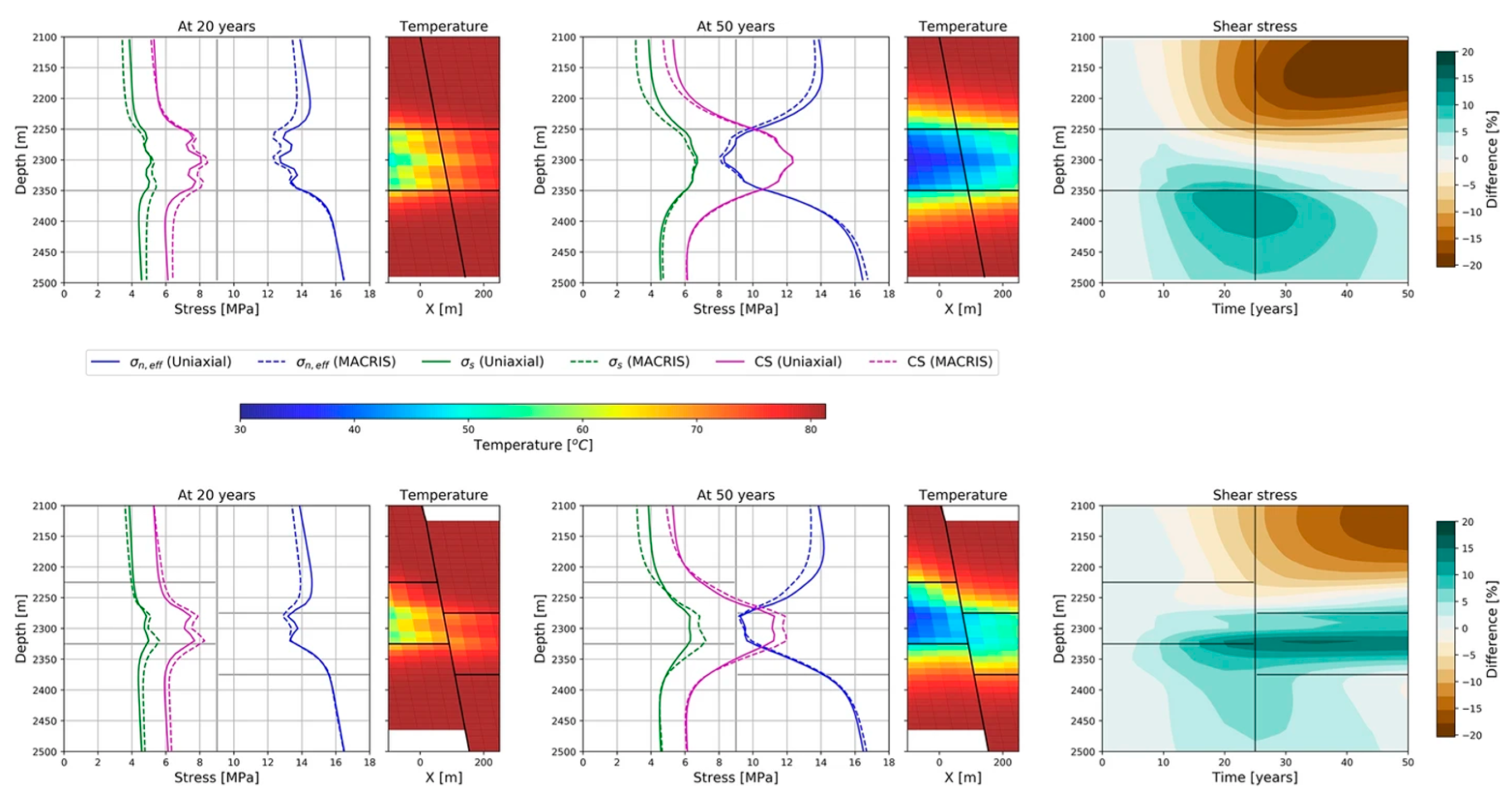
Figure 2: Stress and temperature solutions on the fault plane for a reservoir intercalated with low permeability zones in the case of no fault offset (top row) and normal fault offset (bottom row). The relative difference in shear stress solutions between both approaches is presented over the production lifetime of the geothermal doublet. A positive difference indicates MACRIS to predict a larger stress response compared to the uniaxial solution. The reservoir geometry is outlined in grey/black. Adapted with permission from Reference [37]. Copyright © 2024 Springer.
In the geological disposal of high-level radioactive waste (HLW), hydraulic–mechanical–chemical (HMC) coupling becomes the decisive factor in assessing safety over millennial timescales [38]. After the engineered barrier system (waste canisters and bentonite buffer) initially achieves self-sealing and self-supporting functionality through THM coupling, the long-term safety of the repository relies primarily on the natural barrier properties of the host rock. At this stage, potential migration pathways for radionuclides are entirely governed by the fracture network in the surrounding rock. Long-term groundwater flow H through these fractures is not only influenced by M-controlled evolution of fracture apertures but is also deeply coupled with C-driven mineral dissolution and precipitation reactions. Water–rock interactions can either fill fractures (reducing permeability) or cause alteration and widening (increasing permeability), thereby irreversibly altering the rate and pathways of radionuclide transport [39]. Consequently, HMC coupling models must be capable of capturing these slow yet decisive long-term evolutionary processes, as their predictions directly determine the reliability of safety assessments for the repository.
In deep-buried tunnels and underground caverns, hydraulic–mechanical (HM) coupling is often the direct trigger of engineering hazards [40]. Excavation-induced stress redistribution in the surrounding rock M alters the permeability of the fracture network (M → H). Simultaneously, high-head groundwater H infiltrates the excavation zone through fractures, generating seepage forces and reducing effective stress (H → M), which may lead to large deformations of the surrounding rock, water inrush, or mud gushing disasters. In cold regions where artificial ground freezing (AGF) is employed during construction, TM coupling becomes the dominant mechanism: the advancing freezing front T drives moisture migration and ice lens formation, generating frost heave pressure (T → M) that stabilizes the rock mass. However, freeze–thaw cycles T also cause progressive rock deterioration and induce cyclic variations in the stress state of support structures M, posing a threat to their long-term stability.
In summary, although the fundamental physics of THMC coupling in fractured rock is universal, its engineering manifestation is highly context-dependent. As systematically compared in Table 1, the dominant coupling pathways, governing time scales, and critical control parameters differ markedly across EGS, nuclear waste disposal, and deep tunneling—reflecting their divergent primary objectives (heat extraction, long-term containment, and structural stability) and operational horizons (decades, millennia, and construction-phase control, respectively). While these scenarios share common multiphysics foundations, their risk drivers and modeling priorities are shaped by distinct dominant feedback loops. Successful engineering practice therefore hinges not on applying a universal model, but on selectively emphasizing the relevant subset of coupling processes that dictate system behavior in each specific scenario. This targeted modeling strategy ensures both computational efficiency and physical fidelity, ultimately strengthening the bridge between multiphysics theory and real-world subsurface engineering.
Table 1: Comparative summary of dominant THMC coupling mechanisms across key subsurface engineering applications.
| Aspect | EGS | Nuclear Waste Disposal | Deep Tunnel Engineering |
|---|---|---|---|
| Primary Objective | Efficient, sustained heat extraction | Long-term radionuclide containment (>103 years) | Short-to-medium term stability during/after excavation |
| Dominant Coupling Pathway | H → T → M → H | H ↔ M ↔ C | M ↔ H |
| Cold injection → thermal stress → fracture shear → permeability increase → enhanced flow | Groundwater flow ↔ aperture evolution ↔ mineral reactions → long-term permeability change | Excavation stress redistribution ↔ fracture permeability ↔ seepage pressure → instability | |
| Time Scale | Years to decades (operational lifetime) | Centuries to millennia (post-closure safety) | Days to years (construction + relaxation phase) |
| Key Control Parameters | Injection rate/pressure, in-situ stress ratio, fracture transmissivity, thermal conductivity | Host rock permeability, buffer swelling pressure, groundwater chemistry, mineral reaction kinetics | In-situ stress magnitude/orientation, rock mass quality (RMR/GSI), groundwater head, support stiffness |
| Critical Risk | Thermal breakthrough due to channeling | Radionuclide leakage via altered fracture pathways | Water inrush, mud gushing, or large deformations |
| Modeling Focus | Dynamic TMH feedback, fracture shear activation | Slow HMC evolution, chemical–mechanical feedback | Transient HM response, seepage–stress interaction |
3 Modeling Paradigms and Numerical Methods for Seepage
3.1 Comparative Analysis of Mainstream Modeling Paradigms
The core challenge in modeling fluid flow in fractured rock masses lies in effectively representing their inherent discontinuity and strong heterogeneity. To address this challenge, the research community has developed multiple theoretical modeling paradigms, each based on distinct physical abstractions and mathematical assumptions, resulting in unique trade-offs among computational efficiency, representation accuracy, and suitability for specific applications. The fundamental differences among the three mainstream modeling paradigms—ECM, DFN models, and Dual-Medium models—including their computational efficiency—are summarized in Table 2. This section provides a systematic comparative analysis of these three dominant approaches.
Table 2: Comparative analysis of mainstream modeling approaches for seepage in fractured rock masses.
| Modeling Paradigm | Core Principle | Key Assumptions | Key Advantages | Key Limitations | Typical Application Scenarios |
|---|---|---|---|---|---|
| ECM | Treats the fractured rock mass as a continuous porous medium with equivalent anisotropic permeability. | A statistically REV exists, and rock mass properties are homogeneous at the REV scale. | High computational efficiency; conceptually simple, easy to apply in engineering practice and amenable to parameter inversion. | It struggles to accurately capture strong anisotropy and spatial heterogeneity; the model fails when a REV does not exist. | Large-scale far-field analyses (e.g., regional groundwater flow, far-field assessment of nuclear waste repositories). |
| DFN Model | Explicitly represents the geometry and topological connectivity of individual fractures in three-dimensional space. | Fluid flow occurs predominantly within the fracture network; the permeability of the rock matrix is negligible. | High physical fidelity; capable of accurately capturing localized flow paths and channeling effects. | It incurs high computational costs and is heavily dependent on high-quality, high-resolution fracture data. | Near-field high-resolution simulations (e.g., seepage in tunnel surrounding rock, reservoir stimulation around EGS wells). |
| Dual-Medium Model | Conceptualizes the system as two interacting continua: a low-permeability, high-storage rock matrix and a high-permeability, low-storage fracture network. | Fracture geometry is highly simplified; mass exchange between matrix and fractures is governed by an empirical “shape factor” or transfer function. | It achieves a good balance between computational efficiency and physical fidelity, making it suitable for multiscale fracture systems. | It cannot capture the geometric details and connectivity of individual fractures; the transfer functions lack clear physical meaning, making parameter calibration difficult. | Medium-scale reservoir simulations (e.g., geothermal fields, oil and gas reservoirs, CO2 storage sites). |
The ECM is a “top-down” macroscopic modeling approach. Its core idea is to treat the intrinsically discontinuous fractured rock mass, at a sufficiently large scale, as a continuous porous medium with anisotropic hydraulic properties [40]. The theoretical foundation of this model is the “REV” hypothesis, which posits that when the scale of investigation is much larger than the characteristic fracture spacing, the hydraulic and mechanical properties of the rock mass become statistically homogeneous and can thus be described by an equivalent permeability tensor K that characterizes the overall seepage behavior [41]. This homogenization logic is intuitively illustrated in Fig. 3, which demonstrates how a complex fracture network is upscaled into a single equivalent continuous flow channel to achieve macroscopic representation of seepage characteristics.
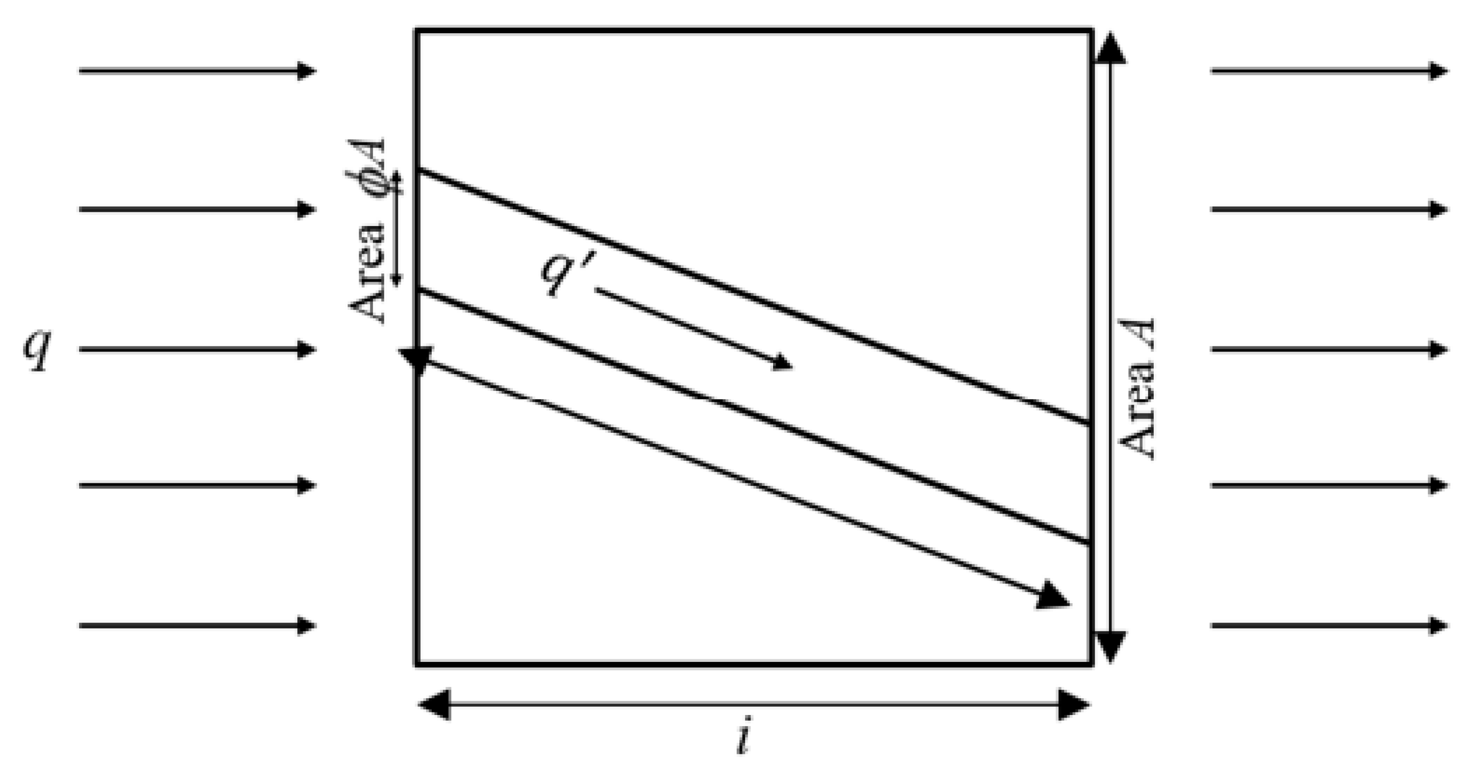
Figure 3: Schematic diagram of equivalent model (Paterson, 1983). I is the unit length of one element, A is the area of cross-section, q is the flow rate, and q′ is the flow rate in equivalent channel. Adapted with permission from Reference [42]. Copyright © 2015 Elsevier.
Advantages:
- High computational efficiency: By simplifying the complex fracture network into a continuous field, the ECM can be seamlessly integrated with well-established numerical methods such as the FEM or Finite Difference Method (FDM). This makes it suitable for large-scale engineering simulations (e.g., at watershed or far-field scales) with relatively low computational cost.
- Conceptual simplicity and strong engineering practicality: Model parameters—such as equivalent permeability—are readily invertible and calibratable using field pumping tests or tracer tests, making the model intuitive and accessible for engineering practitioners.
Limitations:
- Fragility of the REV assumption: In rock masses with sparse, highly heterogeneous, or extremely anisotropic fracture distributions, a statistically REV may not exist. In such cases, the equivalent parameters lose physical meaning, leading to model failure and unreliable predictions.
- Limited ability to represent spatial heterogeneity: ECM inherently adopts an “averaging” approach to the fracture network, making it difficult to capture the controlling influence of localized high-permeability pathways (such as major fractures or faults) on fluid flow trajectories. This often leads to underestimation of extreme-value risks, such as preferential flow or rapid contaminant transport.
- Lack of path dependence: The model typically assumes that permeability is a single-valued function of the current stress state, making it incapable of capturing the hysteresis and irreversible evolution of permeability during stress loading–unloading cycles.
Therefore, the ECM is most suitable for rock masses with high fracture density and relatively uniform fracture distribution, or for preliminary large-scale, low-resolution feasibility studies and regional impact assessments in the early stages of engineering projects [43]. Its success critically depends on the validity of the REV assumption under the specific geological conditions of the site.
The DFN model adopts a “bottom-up” modeling paradigm. Its core principle is to explicitly represent each individual fracture in the rock mass as a discrete geometric entity in three-dimensional space (typically as planar or curved surfaces) [44]. The model is constructed directly from measured or statistically derived fracture parameters, such as location, orientation, size, aperture, and roughness, thereby providing the most physically faithful representation of the discontinuous structure of fractured rock. Within the DFN framework, fluid flow is assumed to occur predominantly within the fracture network, while the rock matrix is typically treated as a low-permeability or impermeable block [45]. This explicit characterization of flow pathways makes DFN an ideal tool for investigating localized seepage paths, solute transport, and preferential flow phenomena.
Advantages:
- High physical fidelity: The DFN model can accurately capture the geometry, spatial orientation, and interconnectivity of individual fractures, thereby revealing the “channeling effect” created by major fractures or faults [46], a feature that ECMs cannot resolve. Its results possess clear physical meaning and can be directly used to analyze key hydrogeological parameters such as flow path tortuosity and the proportion of dead-end fractures.
- Applicability to complex geological conditions: For rock masses with sparse fracturing, extreme anisotropy, or the presence of large-scale structures (e.g., faults), the DFN model does not rely on the REV assumption, thereby offering greater applicability and predictive reliability.
Limitations:
- High computational cost: Explicitly solving fluid flow within each individual fracture and their interactions results in a very high number of degrees of freedom, leading to substantial computational resource demands. This becomes a major bottleneck, particularly when simulating large-scale or high-density fracture networks.
- Stringent data requirements: Model accuracy is highly dependent on the quality and completeness of input fracture geometry and hydraulic parameters. Acquiring a sufficient volume of statistically representative field data—through methods such as borehole imaging, outcrop mapping, or geophysical inversion—is often costly and technically challenging. Uncertainties in these input data propagate directly into the simulation results, affecting their reliability.
- Difficulty in scale upscaling: Extrapolating fracture parameters from small scales (e.g., laboratory or borehole scale) to engineering scales (e.g., kilometer-scale reservoirs) encounters significant scale effects and issues of parameter representativeness, often introducing systematic errors.
In summary, the DFN model, with its unparalleled geometric fidelity, has become the method of choice for near-field, high-resolution analyses—such as seepage around tunnel linings or simulations of the stimulated zone surrounding wells in EGS. However, its high computational cost and strong dependence on high-quality input data limit its applicability to localized, high-precision simulations of critical zones, rather than large-scale, system-wide assessments [47].
3.1.3 Dual-Porosity/Dual-Permeability Model
The Dual-Medium Model (Dual-Porosity/Dual-Permeability Model) is a hybrid, compromise-oriented modeling paradigm designed to bridge the gap between the macroscopic simplification of ECM and the microscopic complexity of DFN models [48]. Its core principle conceptualizes fractured rock as comprising two interconnected yet physically distinct subsystems: a high-permeability, low-storage fracture network, and a low-permeability, high-storage rock matrix [49]. This model acknowledges that rapid fluid transport through fractures is the dominant flow process, while simultaneously accounting for the matrix’s long-term role as a reservoir for fluid storage and solute diffusion.
In the classical Dual-Porosity Model, fluid flow is assumed to occur only within the fracture network at the macroscopic scale, while the matrix is treated as a stagnant “block” that exchanges fluid with fractures solely through diffusion or very slow imbibition. This formulation is suitable for scenarios where the matrix permeability is extremely low—such as in shale or tight sandstone. The more advanced Dual-Permeability Model further allows for slow but non-negligible fluid flow within the matrix itself, thereby providing a more realistic representation of bidirectional mass exchange between the matrix and the fracture network [50].
Advantages:
- Balanced computational efficiency and fidelity: This near-linear scaling enables large-scale reservoir simulations (e.g., geothermal fields, CO2 storage) where rapid scenario testing is essential.
- Multi-scale fracture handling: Aggregates structural and micro-fractures into a single fracture continuum, parameterizing multi-scale effects computationally tractably.
- Extensibility: Enhanced variants (e.g., EDPDP) incorporate stress-dependent apertures and nonlinear flow laws without significant computational overhead.
Limitations:
- Oversimplified fracture geometry: Loses individual fracture connectivity, making it incapable of capturing channeling effects (unlike DFN).
- Transfer function uncertainty: Empirical “shape factors” are highly sensitive to calibration data, introducing significant prediction errors.
- Anisotropy representation: Anisotropic tensors lack direct physical linkage to fracture geometry (unlike DFN), reducing accuracy in strongly anisotropic systems.
3.2 Evaluation of Numerical Modeling Approaches
Theoretical modeling paradigms provide a conceptual framework for fluid flow in fractured rock masses, while their practical engineering implementation heavily relies on efficient and robust numerical methods. Different numerical algorithms each possess distinct advantages and limitations in handling geometric complexity, physical nonlinearity, and multi-physics coupling. A comparative analysis of these mainstream numerical methods is presented in Table 3. This section systematically evaluates four widely used numerical approaches—FEM, DEM, Boundary Element Method (BEM), and LBM—to inform the synergistic selection of models and algorithms.
Table 3: Comparative analysis of mainstream numerical modeling methods for fractured rock masses.
| Numerical Method | Discretization Strategy | Key Advantages | Main Limitations | Typical Engineering Applications |
|---|---|---|---|---|
| FEM | Grid-based: discretizes the entire computational domain. | Widely applied; excels at handling complex geometric boundaries; readily enables strong coupling of multiphysics processes (e.g., THM). | Prone to mesh distortion under large deformations, requiring remeshing; high-fidelity simulations demand extremely fine meshes, leading to high computational costs. | Seepage analysis in dams, slope stability assessment, tunnel support design. |
| DEM | Particle-based: discretizes the rock mass into interacting blocks or particles. | Naturally suited for simulating large deformations, fracture, and progressive failure in discontinuous media; capable of capturing micromechanical behavior. | Macroscopic mechanical parameters must be obtained through calibration; computational cost increases exponentially with system size. | Rock slope failure analysis, rockfall dynamics, hydraulic fracturing process simulation. |
| BEM | Boundary-based: discretizes only boundaries and fractures. | Dimensionality reduction leads to high computational efficiency; especially well-suited for fracture problems with high surface-area-to-volume ratios; no internal mesh required. | Struggles with strongly heterogeneous materials; encounters numerical difficulties in resolving low-angle fracture intersections; tends to produce dense matrices for large-scale problems, leading to reduced computational efficiency. | Seepage in fractured porous media, contact mechanics problems, acoustic problems. |
| LBM | Lattice-based: simulates particle distribution functions at the mesoscale. | Inherently adept at capturing complex nonlinear flow phenomena (e.g., vortices, backflow); highly adaptable to complex geometries such as rough fracture walls. | Algorithms for handling complex boundary conditions incur high computational overhead; simulation techniques for dynamically evolving geometries are still under development. | High-fidelity mesoscale simulation of fluid flow in rough fractures, microfluidic device design. |
The FEM and the FDM are the most widely used numerical techniques for solving partial differential equations, particularly dominating the field of geotechnical engineering [51]. Both methods discretize the continuous solution domain into a finite number of elements or grid points, transforming the governing equations into large systems of algebraic equations for numerical solution.
The core strength of FEM lies in its ability to handle complex geometric boundaries and strongly coupled multi-physics processes. Through flexible mesh discretization, FEM can accurately conform to irregular engineering structures such as tunnels and caverns. Moreover, it naturally integrates the governing equations of THMC fields within a unified variational framework, enabling fully coupled THMC simulations [52]. Additionally, FEM offers well-established formulations for modeling material nonlinearity, such as elastoplastic constitutive behavior.
However, FEM faces two major challenges: First, when simulating large deformations or fracture propagation, the mesh can suffer severe distortion, leading to numerical instability and necessitating frequent remeshing, which incurs high computational costs [53]. Second, accurately resolving strong discontinuities such as fractures requires extremely fine meshes, significantly increasing the number of degrees of freedom [54]. To address these limitations, hybrid FEM-DEM approaches have been developed—employing FEM in macroscopically continuous regions while embedding DEM in localized fracture zones—thereby enabling a unified simulation of both continuous deformation and discontinuous failure.
Although the FDM is conceptually simpler and computationally efficient on regular grids, it lacks flexibility in handling complex geometric boundaries and struggles to achieve natural coupling of multi-physics processes. Consequently, its application in high-fidelity simulations of fractured rock masses has been increasingly superseded by the FEM.
The DEM fundamentally abandons the continuum assumption, treating rock masses as assemblies of discrete blocks or particles that interact through contact mechanics models—such as spring-dashpot systems [55]. This intrinsic feature makes DEM naturally suited for simulating discontinuous processes, including large deformations, progressive failure, and fracture evolution.
In fractured rock research, DEM can explicitly reproduce fracture opening, closure, sliding, as well as the initiation and coalescence of new fractures—without requiring predefined fracture paths. This offers a unique perspective for investigating engineering problems involving strong discontinuities, such as hydraulic fracturing, rockbursts, and slope instability. Its micromechanical framework is transparent, enabling a direct link between macroscopic responses and the evolution of microstructural features.
However, DEM also has significant limitations. First, its macroscopic mechanical parameters—such as elastic modulus and strength—are not intrinsic material properties; instead, they are derived through a calibration process that inversely maps microscopic contact parameters to macroscopic behavior. This process is time-consuming and often non-unique [56]. Second, the computational cost of DEM scales exponentially with system size, posing a severe computational bottleneck for large-scale engineering applications. Consequently, DEM is best suited for small-scale, mechanism-focused studies or, alternatively, as a complement to FEM for high-fidelity analysis of localized high-risk zones.
The BEM is a dimensionality-reduced numerical technique based on boundary integral equations. Its core idea is to discretize only the boundaries of the solution domain—including fracture surfaces—without requiring meshing of the interior region [57]. This feature enables BEM to achieve exceptional computational efficiency when dealing with problems characterized by a high surface-area-to-volume ratio.
For rock masses where flow is predominantly channeled through fracture networks, BEM can accurately represent fracture geometry and their hydraulic interactions with far fewer degrees of freedom, thereby avoiding the redundant computational effort associated with interior meshing in FEM. Moreover, BEM inherently satisfies far-field (infinite-domain) boundary conditions, giving it a distinct advantage in modeling unbounded problems such as far-field seepage.
However, the application of BEM is also constrained by its inherent limitations. First, its fundamental solutions rely on assumptions of homogeneous, linear-elastic media, making it difficult to effectively handle strongly heterogeneous materials—such as those with multiple lithological layers or complex rock matrices [58]. Second, numerical difficulties arise when dealing with low-angle intersecting fractures due to singularities in the integral equations [59]. Finally, for large-scale problems, BEM typically yields a dense system matrix, whose storage and solution costs increase rapidly with problem size, thereby limiting its applicability to very large simulations [60].
The LBM is a mesoscale numerical approach rooted in statistical mechanics, which solves the Navier-Stokes equations by simulating the collision and streaming of fluid particles on a regular lattice [61]. LBM offers unique advantages in modeling nonlinear fluid flow within complex geometric boundaries.
For fractured rock masses, LBM can directly simulate flow over digitized, rough fracture walls without relying on simplified geometric assumptions, accurately capturing complex flow phenomena such as eddies, backflow, and flow separation induced by surface roughness. Numerous studies have shown that permeability values obtained from LBM simulations are often significantly lower than those predicted by the cubic law based on the idealized parallel-plate assumption, revealing a systematic bias in traditional models under high flow velocities or complex geometries [62]. Furthermore, LBM demonstrates strong potential in handling complex flow scenarios, including multiphase flow and non-Newtonian fluids.
However, despite its high physical fidelity at the pore and fracture scale, the LBM confronts considerable limitations in computational efficiency and scalability for engineering-scale applications. These constraints arise from several inherent features of the method:
Explicit time integration: LBM relies on an explicit time-marching scheme subject to a stringent stability criterion, which typically demands very small time steps in diffusive regimes. Consequently, it requires significantly more time steps than implicit FEM solvers to simulate the same physical duration.
Substantial memory requirements: Each lattice node must store multiple distribution functions, leading to a large memory footprint per node. In contrast, FEM generally stores only primary field variables along with sparse matrix data, resulting in considerably lower memory usage for comparable spatial resolution.
Computational cost: Although LBM exhibits near-linear scaling per time step with respect to the number of lattice nodes, the overall computational expense grows rapidly with both physical time and domain size. For realistic fracture-scale simulations, this can lead to prohibitive runtimes, hindering parametric analyses or uncertainty quantification.
Parallel scaling limitations: While LBM demonstrates strong scaling on GPU-based systems due to its localized update rules, its weak scaling tends to degrade beyond certain problem sizes because of inter-process communication overhead. This makes it less suited for extreme-scale reservoir simulations compared to FEM with advanced solvers or other particle-based methods with efficient domain decomposition.
Hardware dependence: Achieving practical performance in LBM simulations strongly depends on GPU acceleration. CPU-only implementations are markedly slower, rendering them infeasible for large three-dimensional fracture networks beyond laboratory scale.
Moreover, current LBM implementations primarily focus on hydraulic field modeling; efficiently and robustly integrating LBM into a full THMC multiphysics framework remains a key direction for future research. Consequently, while LBM excels in high-fidelity microscale analysis of single fractures or small fracture clusters, its computational demands currently preclude routine use in large-scale, field-level THMC simulations—unless hybrid strategies (e.g., LBM for critical zones + FEM for far-field) are adopted.
Despite its promising potential, LBM still faces challenges in engineering applications. Algorithms for handling complex boundary conditions—such as dynamically moving boundaries—entail substantial computational overhead, and simulation techniques for time-evolving geometries (e.g., shear-induced slip or chemical dissolution) remain under active development. Moreover, current LBM implementations primarily focus on hydraulic field modeling; efficiently and robustly integrating LBM into a full THMC multiphysics framework remains a key direction for future research.
3.3 Model Selection Strategy and Applicability
In the study of fluid flow through fractured rock masses, the choice of theoretical model is not merely a technical issue but a strategic decision that can determine the success or failure of a project. The core principle lies in identifying and focusing on the dominant physical processes specific to the engineering problem at hand, and seeking an optimal balance among computational cost, data availability, and prediction accuracy. Fig. 4 intuitively demonstrates the practical value of simplified models in this balance: it presents a reference case of a homogeneous isotropic fracture network (a typical simplified idealized model), which can efficiently output key engineering-relevant results such as solute breakthrough curves, pressure difference distributions, and solute concentration fields—providing reliable macroscopic trend assessments for preliminary feasibility studies. An effective decision-making framework should integrate three key dimensions: project scale, data availability, and required accuracy, ensuring that the selected model is both computationally efficient and capable of delivering reliable, engineering-relevant results.
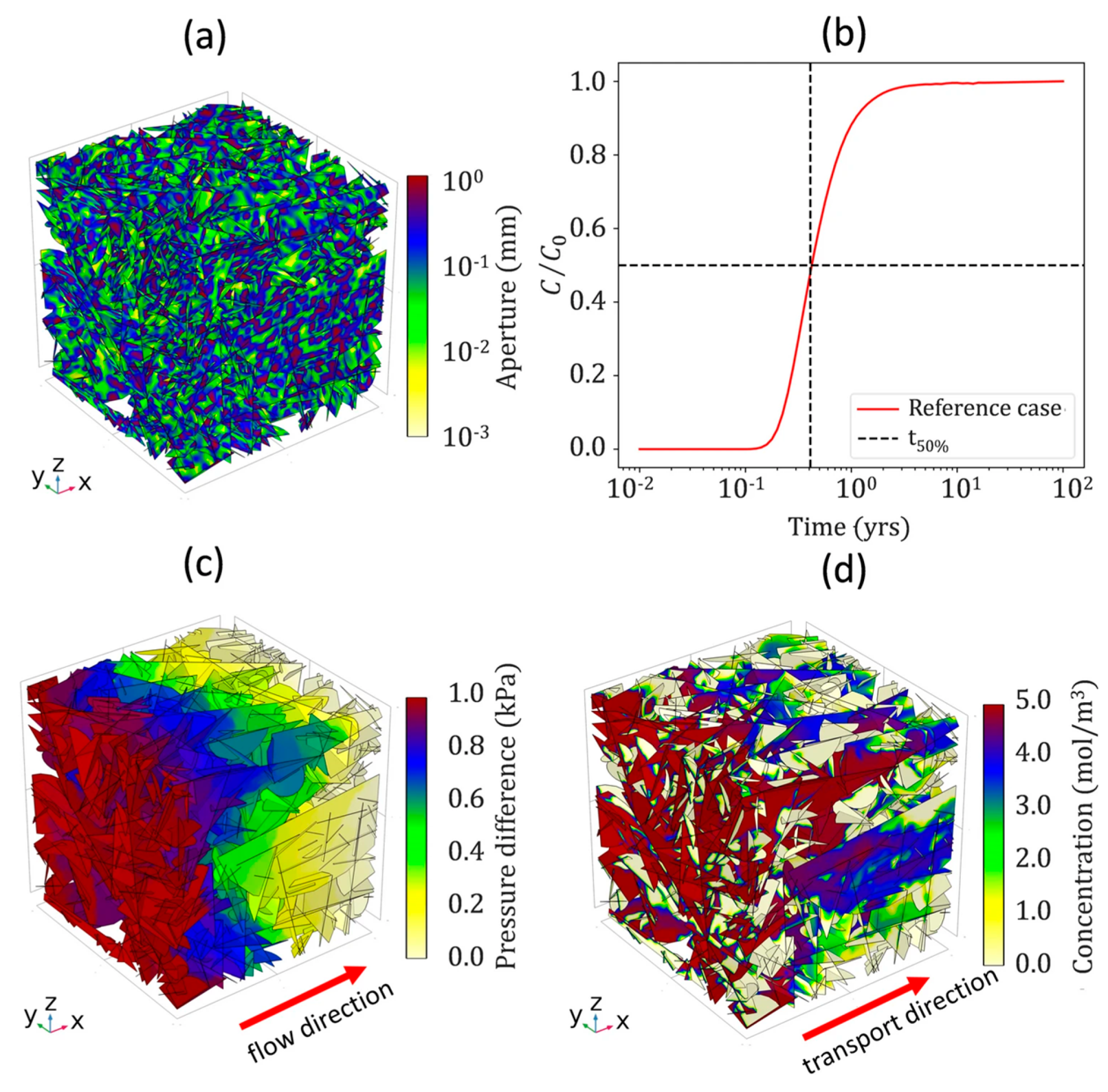
Figure 4: A reference case of isotropic fracture network: (a) aperture distribution with k = 1 and uncorrelated aperture distribution and (b) solute breakthrough curve (BTC) with its median travel time (time at 50% of the BTC), (c) pressure difference distribution in the fracture network above the exit-face pressure, and (d) solute concentration in the network at 0.5 years. Adapted with permission from Reference [63]. Copyright © 2025 Springer.
Decision Framework:
- (1)Project Scale and Spatial Extent:
- Large-scale/far-field analyses (e.g., regional groundwater flow, far-field impact zones of nuclear waste repositories): ECM are preferred. They offer high computational efficiency and are suitable for simulations at the kilometer scale, providing macroscopic, homogenized flow field distributions that meet strategic-level assessment requirements.
- Medium-scale/reservoir-scale problems (e.g., geothermal fields, oil and gas reservoirs): The dual-porosity/dual-permeability model is an ideal choice. It strikes a favorable balance between computational efficiency and physical fidelity, effectively capturing mass exchange between the rock matrix and fracture network, and is well-suited for complex systems with multiscale fracture networks.
- Small-scale/near-field analyses (e.g., tunnel surrounding rock, EGS wellbore stimulation zones, near-field of nuclear waste canisters): DFN models are essential. Only DFN can accurately capture critical mechanisms such as localized high-permeability pathways, fracture connectivity, and shear-induced slip, providing microscale insights necessary for high-fidelity design and safety assessment in high-risk zones.
- (2)Data Availability and Quality:
- Rich and high-quality data: When detailed fracture characterization data are available—such as borehole imaging, outcrop statistics, or geophysical inversion results—the DFN model can fully leverage its advantages, delivering high-fidelity predictions of significant engineering value.
- Limited or moderate-quality data: Under conditions of data scarcity or high uncertainty, ECM or dual-porosity models are more robust. They exhibit lower sensitivity to input parameters and can be calibrated through macroscopic field observations—such as pumping test data—thereby reducing the risk of model failure due to insufficient or uncertain data.
- (3)Required Accuracy and Engineering Objectives:
- High-accuracy, mechanism-focused studies: When the objective is to gain deep insight into flow pathways, solute transport mechanisms, or to assess localized hazard risks (e.g., water inrush or mud bursting), computational efficiency must be sacrificed in favor of DFN models to achieve the most physically realistic simulation of the underlying processes.
- Moderate accuracy, system-level evaluation: For optimizing system performance (e.g., EGS heat extraction efficiency or oil/gas recovery rates) or conducting comparative evaluations of multiple design scenarios, dual-porosity models are generally sufficient to provide reliable decision support.
- Low accuracy, feasibility studies: During early project stages or large-scale reconnaissance, ECM are the preferred choice for initial screening and macroscopic trend assessment due to their speed and low computational cost.
The successful application of any theoretical model fundamentally depends on the close alignment between its core assumptions and the actual geological conditions of the target rock mass. For example:
- The ECM relies on the existence of a REV. If applied to sparsely fractured or highly anisotropic rock masses where REV does not exist, the equivalent hydraulic parameters lose physical meaning, leading to predictions that significantly deviate from reality [64].
- The DFN model assumes that fluid flow occurs primarily within fractures, with the rock matrix treated as impermeable. If the matrix permeability of the target rock mass is non-negligible (e.g., in shale), a dual-permeability model must be adopted; otherwise, the storage capacity and diffusive contribution of the matrix will be significantly underestimated [65].
- The dual-porosity model simplifies the exchange process between fractures and matrix through a “transfer function”. In regions with extremely complex fracture network topology or dominant preferential flow pathways, this simplification may lead to misidentification of critical flow channels [66].
Therefore, model selection should not be a rigid, one-size-fits-all application, but rather a dynamic, iterative process of adaptation. Engineers must deeply understand the physical underpinnings and inherent limitations of each model and, in conjunction with thorough site-specific geological investigations, carefully evaluate the validity of model assumptions in the given context. Only in this way can theoretical models be effectively transformed into powerful tools for solving real-world engineering challenges—rather than becoming “black boxes” that produce misleading results.
4 Experimental Foundations of Seepage Characteristics
4.1 Single-Fracture Flow Experiments
Single-fracture flow experiments form the cornerstone for understanding the hydro-mechanical coupling behavior of fractured rock masses. By applying controlled normal stress, shear displacement, and fluid pressure to a single fracture—either artificial or natural—within rock specimens, researchers can isolate the effects of complex fracture networks and directly observe and quantify the constitutive relationships among stress state, geometric morphology, and fluid flow. Extensive experimental data consistently demonstrate that fracture permeability is not a material constant; rather, it is a highly nonlinear, path-dependent state variable jointly governed by effective stress and shear deformation [67]. Fig. 5 illustrates the evolution of hydraulic and maximum apertures with applied displacement during the simulation of a brittle rock. The hydraulic aperture, a key parameter directly correlating with fracture permeability, exhibits a distinct nonlinear response to shear displacement, further validating the path-dependent nature of permeability in fractured rock masses.
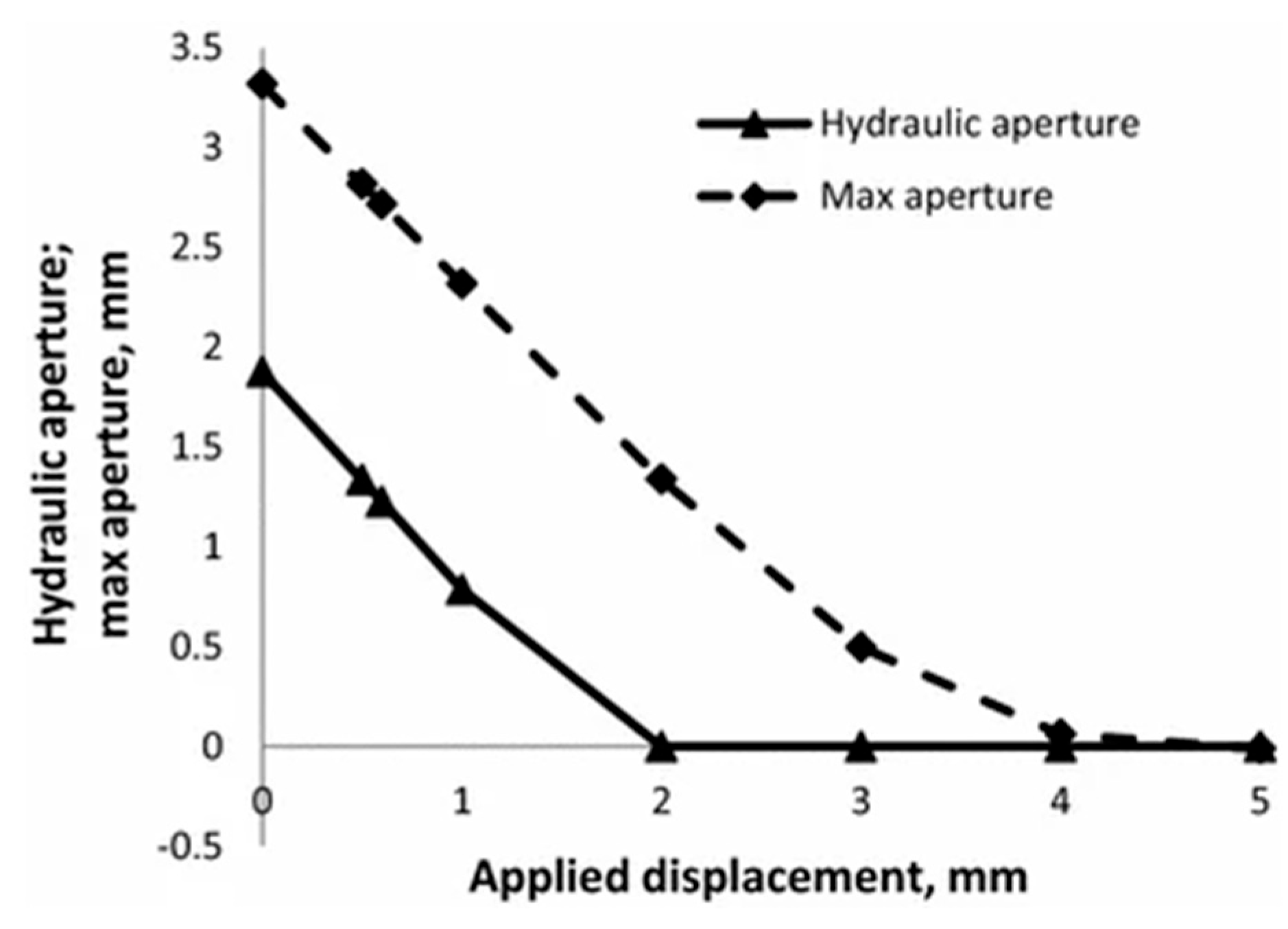
Figure 5: Hydraulic and maximum apertures versus applied displacement obtained in the simulation of a ‘brittle’ rock. Hydraulic aperture obtained with for flow in x-direction. Adapted with permission from Reference [68]. Copyright © 2016, Springer.
4.1.1 Nonlinear Control Mechanism of Effective Stress
Experimental results clearly confirm that as normal effective stress increases, the mean aperture of a fracture decreases nonlinearly while the variance of the aperture distribution increases, causing permeability to drop sharply—often by several orders of magnitude [69]. This phenomenon arises from the progressive increase and compaction of contact points between fracture walls. Mathematically, this relationship is commonly described by exponential decay or power-law functions. More importantly, the process exhibits pronounced hysteresis: during unloading, the recovery of permeability is significantly less than the loss observed during loading, indicating that part of the deformation is irreversible. This nonlinearity and hysteresis fundamentally challenge the applicability of traditional linear elastic models, necessitating the incorporation of damage or plasticity mechanisms into theoretical models to accurately capture the evolutionary history of fracture permeability.
4.1.2 Three-Stage Evolution of Shear Displacement and Roughness
When a fracture is subjected to shear displacement under constant normal stress, its permeability evolution follows a characteristic three-stage pattern:
- (1)Initial compression stage: Minor shear displacement induces “shear closure” of the fracture walls, increasing the contact area and causing a slight decrease in permeability.
- (2)Rapid dilation stage: As shear displacement further increases, microscopic asperities on the fracture walls undergo shear failure and ride-over, triggering macroscopic “shear dilation”. This leads to a significant increase in aperture and an exponential rise in permeability.
- (3)Stable residual stage: After dilation peaks, the fracture walls either become smoother or establish new stable contacts, causing the rate of permeability increase to slow down and eventually stabilize.
Fracture roughness is the key parameter governing this process. Experiments show that rougher fracture walls exhibit greater dilation potential and achieve higher peak permeability. This “dilation-induced permeability enhancement” mechanism forms the physical basis for artificially activating reservoir permeability in engineering applications such as EGS. Accurate prediction of this behavior is therefore critical to project success [70].
4.1.3 Non-Darcy Flow Behavior and the Forchheimer Equation
Under high flow velocities or large aperture conditions, fluid flow through fractures deviates from the classical linear Darcy’s law and exhibits non-Darcy behavior dominated by inertial effects. Typical experimentally observed phenomena include a nonlinear relationship between flow velocity and pressure gradient, the emergence of localized vortices and recirculation zones, and a significant increase in kinetic energy losses. To accurately describe such complex flow regimes [71], the Forchheimer equation has been widely adopted:
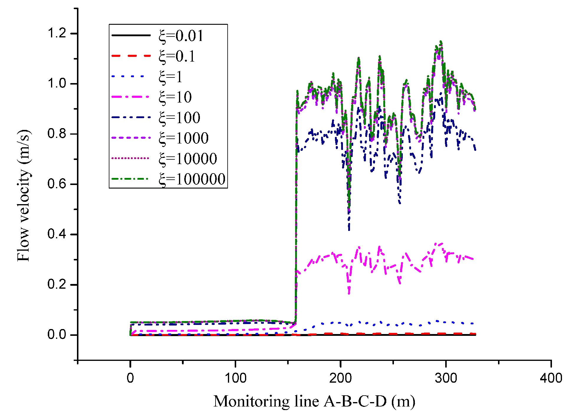
Figure 6: Velocity distribution of monitoring line at different permeability ratios. Adapted with permission from Reference [72]. Copyright © 2019, MDPI.
In summary, single-fracture experiments not only provide essential constitutive parameters but also profoundly reveal the core physical mechanisms governing fracture flow: its behavior is a dynamic outcome of the interplay among stress history, geometric morphology, and flow regime. These insights offer indispensable physical constraints and validation benchmarks for developing high-fidelity theoretical models and numerical simulations. The key influencing factors and their governing relationships have been synthesized in Table 4.
Table 4: Synthesis of key experimental parameters influencing permeability evolution in fractured rock masses.
| Experimental Parameter | Impact on Permeability | Key Physical Mechanisms and Findings | Typical Engineering Applications |
|---|---|---|---|
| Normal Effective Stress | Decreases nonlinearly and exponentially with increasing stress; exhibits incomplete recovery during unloading, showing pronounced hysteresis and path dependence. | Mean fracture aperture decreases while aperture distribution variance increases; the growth in contact area drastically constricts hydraulic flow pathways. Stress history is a critical determinant of the current permeability state. | Tunnel surrounding rock stability assessment, nuclear waste repository barrier design, deep drilling risk management. |
| Shear Displacement | Exhibits a three-stage nonlinear evolution: initial compressive closure → rapid dilation-induced expansion → stable residual stage. | Dilation is the core mechanism: asperity ride-over during shearing causes macroscopic aperture increase. The peak permeability is positively correlated with wall roughness. The Forchheimer equation effectively captures the nonlinear flow behavior under high-velocity shear conditions. | EGS reservoir stimulation, hydraulic fracturing optimization, induced seismicity risk assessment. |
| Anisotropic Stress Field | Permeability becomes highly anisotropic, decreasing exponentially with increasing maximum principal stress; lateral stress can induce a “tensile effect” that promotes fracture opening. | Stress-induced “channeling effect”: fluid flow becomes concentrated along high-conductivity pathways formed by shear slip. The angle between fracture orientation and the principal stress direction is a key geometric parameter controlling permeability anisotropy. | Oil and gas reservoir development (reservoir pressure depletion management), geothermal field production optimization, interaction analysis of deep underground cavern groups. |
| Fracture Roughness | Positively controls dilation potential: rougher fracture walls generate greater shear-induced dilation during shearing, leading to higher peak permeability. | Roughness violates the laminar flow assumption, inducing vortices and recirculation zones, which cause the actual permeability to be significantly lower than predictions from the idealized cubic law. The Forchheimer equation provides a more accurate nonlinear flow model for such conditions. | Applicable to all engineering scenarios involving fracture flow; serves as essential input parameters for high-fidelity modeling approaches such as DFN and LBM. |
4.2 Triaxial Seepage Experiments
While single-fracture experiments reveal fundamental stress–seepage coupling mechanisms, triaxial seepage experiments—by applying an anisotropic stress field (i.e., three unequal principal stresses,
4.2.1 Exponential Decay under Anisotropic Stress Fields
Under triaxial stress conditions, the permeability of fractured rock masses exhibits strong directional dependence and nonlinear decay. Experimental data consistently show that as the maximum principal stress (typically the axial stress,
4.2.2 The “Tensile Effect” of Lateral Stress
A key and counterintuitive finding is that lateral stress (confining pressure
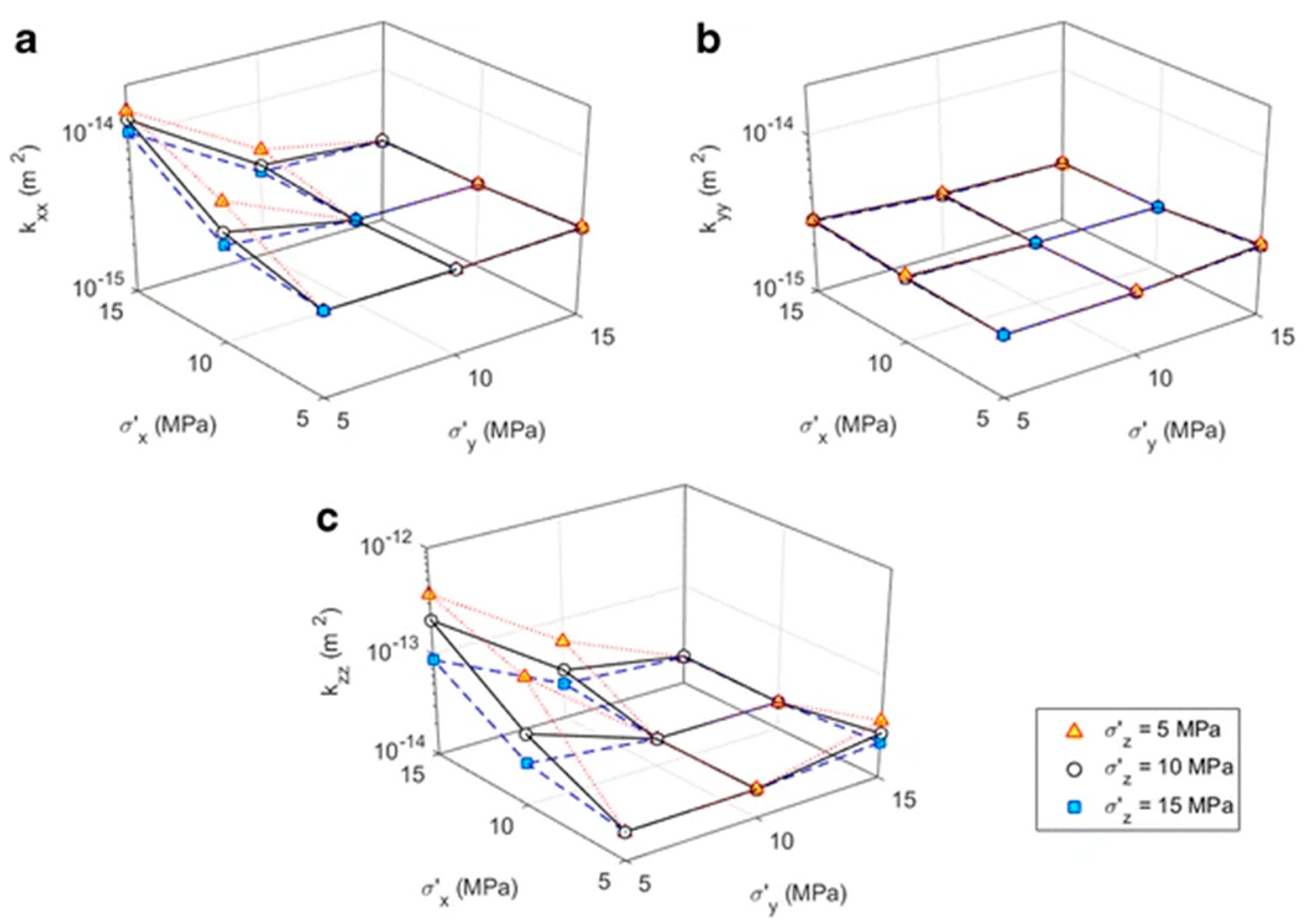
Figure 7: Variation of the equivalent permeability components (a)
4.2.3 Stress-Induced “Channeling Effect” and Its Engineering Implications
One of the most profound insights from triaxial experiments is the direct observation and validation of the stress-induced “fluid channeling” effect. When the deviatoric stress (
This effect carries significant engineering implications:
- In oil/gas and geothermal development, the “channeling effect” is a double-edged sword. On one hand, it can be deliberately harnessed to enhance reservoir permeability; on the other hand, excessive channeling can lead to “thermal breakthrough” or “gas coning”, drastically shortening the operational lifespan of the system.
- In tunneling and underground engineering, stress redistribution induced by excavation can activate fracture networks oriented in specific directions, creating sudden, high-conductivity water inrush pathways that may result in catastrophic failures.
- In nuclear waste disposal, long-term TM perturbations may alter the connectivity of the host rock fracture network, causing unpredictable redirection of radionuclide migration pathways.
Therefore, triaxial seepage experiments not only provide critical constitutive parameters but also reveal the systemic, heterogeneous, and path-selective nature of fluid flow in fractured rock masses. These findings serve as a clear warning: any model that neglects the interaction between stress anisotropy and the spatial geometry of fractures will fail to capture the “channeling effect”—a core physical process that often determines the success or failure of engineering projects.
4.3 Challenges in Scaling from Laboratory to Field Conditions
Extrapolating high-precision experimental data obtained at the laboratory scale to engineering field scales remains a long-standing and unresolved core bottleneck in the study of fluid flow in fractured rock masses. Numerous studies have confirmed that key parameters—such as permeability and reaction rates—measured in the lab often differ by orders of magnitude from those observed in situ or predicted by field-scale simulations. This “scale effect” is not merely a measurement error but stems from fundamental disparities between laboratory and field conditions in terms of system complexity, boundary constraints, and temporal scales [77].
4.3.1 Root Causes of Orders-of-Magnitude Discrepancies
Laboratory experiments—whether single-fracture tests or small-scale triaxial core tests—typically involve sample volumes ranging from a few cubic centimeters to a few liters. While such micro- or meso-scale experiments enable precise control of variables and reveal fundamental physical mechanisms (e.g., stress–permeability relationships, shear dilation), their results inherently describe an “idealized” or “localized” system. In contrast, in-situ rock masses constitute highly heterogeneous, multiscale, and dynamically coupled systems that encompass millions of fractures, span kilometers in spatial extent, and have evolved over millions of years [78]. Laboratories cannot replicate the following critical field-scale characteristics:
- Topological complexity of fracture networks: In the field, fractures are randomly distributed in three-dimensional space, intersecting and forming intricate, interconnected networks. Single-fracture laboratory experiments entirely neglect fracture–fracture interactions, while small-scale core tests are generally unable to capture large-scale structural features—such as dominant flow channels or dead-end clusters—that govern system-wide flow behavior.
- Irreproducibility of geological history: The current state of in-situ rock masses is the product of a long and complex geological history—including tectonic events, fluid–rock interactions, and stress evolution. Laboratory tests can only simulate a specific, instantaneous loading path and cannot replicate this prolonged, multiphysics evolutionary history.
- Significant disparity in boundary conditions: Laboratory tests employ artificially imposed and highly idealized boundaries (e.g., constant stress or constant flow rate), whereas in-situ rock masses exist within complex, evolving in-situ stress fields, temperature fields, and hydraulic gradients, where boundary conditions vary dynamically in both space and time.
4.3.2 Linking Laboratory Observations to Field-Scale Discrepancies
The triaxial seepage experiments reveal a pronounced stress-dependent anisotropy in permeability: under differential stress
This discrepancy is not merely quantitative but reflects a fundamental representational gap: our laboratory samples capture only the matrix and microfracture response within a localized volume, whereas field-scale permeability is dominated by sparse, highly conductive fracture corridors that are statistically unlikely to be intersected by a small core. Consequently, while the directional sensitivity of permeability to stress observed in the lab provides valuable insight into the orientation of potential flow pathways at larger scales, the magnitude must be upscaled using network-based approaches that account for the probability of intersecting major discontinuities. In this sense, the experimental data serve as a constitutive foundation for microscale behavior, but cannot alone predict macroscale transmissivity without explicit integration into a multiscale framework.
4.3.3 The Theoretical Gap from Single Fractures to Complex Networks
Directly “linearly superimposing” or “averaging” single-fracture constitutive relationships—such as the cubic law or the Forchheimer equation—to predict the behavior of complex fracture networks is theoretically invalid [79]. This is because:
- (1)Nonlinearity and path dependence are amplified: The stress–permeability relationship of a single fracture is already nonlinear and path-dependent. In a complex network, deformation of one fracture redistributes stress to neighboring fractures, causing the entire system to exhibit even stronger nonlinearity, hysteresis, and unpredictability. Consequently, the effective permeability of the network is not a simple summation of individual fracture permeabilities.
- (2)Emergence of collective phenomena: Complex fracture networks exhibit macroscopic behaviors that do not exist in isolated single fractures—most notably the “fluid channeling” effect. Under stress, certain fractures dilate and become high-conductivity pathways while others close, causing flow to concentrate intensely along a few dominant channels. This results in pronounced anisotropy and strong non-Darcy flow characteristics at the system scale—phenomena that cannot be directly predicted from single-fracture experiments.
- (3)The mathematical challenge of scale bridging: Deriving macroscopic equivalent constitutive relationships for rock masses from the physical laws governing individual fractures (microscale) remains a central challenge in multiscale modeling. Traditional homogenization theories often fail when applied to strongly heterogeneous and discontinuous media. There is an urgent need to develop new mathematical frameworks—such as nested coupling strategies or data-driven cross-scale correlation models—to rigorously link processes across scales.
Therefore, bridging the scale gap between laboratory and field cannot be achieved merely by enlarging sample size or improving measurement precision. It requires a dual-pronged approach combining theoretical innovation and technological integration: on one hand, developing multiscale coupling theories capable of linking microscale mechanisms to macroscale behavior; on the other, leveraging AI and ML to learn from sparse field data and constrain model parameters, thereby enabling an effective transition from “laboratory physics” to “field engineering”. Successfully addressing this challenge will be a pivotal step in advancing fractured rock seepage research from mechanistic understanding toward precise, predictive capability.
5 Case Studies in Engineering Applications
5.1 Bridging Scales: From Laboratory Constitutive Laws to Field-Scale Fracture Network Models
The engineering applications discussed—nuclear waste disposal, EGS, and deep tunneling—all rely fundamentally on accurate predictions of fluid flow through complex fracture networks under coupled THMC conditions. However, the constitutive relationships governing fracture-scale seepage (e.g., nonlinear Forchheimer flow, stress-dependent aperture-permeability laws) are primarily derived from controlled laboratory experiments on single fractures or triaxial rock cores. A critical challenge lies in how to upscale these microscale, often highly nonlinear, relations to inform macroscale models of heterogeneous fracture systems. Two complementary strategies have emerged to address this scale gap.
First, mathematical homogenization theory provides a rigorous framework to derive effective continuum properties from local physics. By solving boundary-value problems over REVs of a fracture network—subject to lab-calibrated constitutive laws—one can obtain an equivalent, pressure- and stress-dependent permeability tensor
Second, when fracture networks are sparse or highly anisotropic (e.g., in crystalline host rock for nuclear disposal or EGS reservoirs), the REV assumption breaks down. In such cases, nested multi-scale coupling offers a more physically faithful alternative: explicitly modeled fractures in a DFN are assigned constitutive parameters directly calibrated from laboratory experiments (e.g., shear-dilation-permeability curves from triaxial tests), while background matrix or minor fractures may use simplified relations. This strategy ensures that critical flow pathways—governing radionuclide migration or heat extraction—are governed by high-fidelity physics, without sacrificing computational feasibility.
5.2 Nuclear Waste Geological Disposal: Ensuring Long-Term Safety through THMC Coupling
The deep geological disposal of HLW is one of the most challenging long-term engineering endeavors humanity has undertaken. Its design objective is to safely isolate radionuclides from the biosphere over geological timescales of tens of thousands to hundreds of thousands of years [80]. Achieving this ambitious goal critically depends on a profound understanding and accurate modeling of coupled THMC processes [81]. A geological repository is not a static “container” but a dynamic system composed of engineered and natural barriers that continuously evolve under the influence of a thermal pulse. Its long-term safety is, in essence, the outcome of the spatiotemporal interplay of THMC coupling mechanisms.
5.2.1 THM Coupling Mechanisms in the Multi-Barrier System
Modern nuclear waste repositories employ a “multi-barrier” design philosophy, centered on three interdependent subsystems: the waste canister, the bentonite buffer layer, and the surrounding host rock. The functionality of each barrier is critically governed and finely regulated by coupled THM processes [82].
- Waste Canister: As the first line of defense, the waste canister’s primary function is to encapsulate the waste and provide initial mechanical protection. However, its more critical role is that of a powerful heat source. The thermal energy released by radioactive decay (the thermal pulse) serves as the primary driver for the entire system’s evolution. Numerical simulations show that the canister surface temperature can initially reach 80–100°C, with thermal effects extending several meters into the surrounding barriers. This thermal pulse is not merely a “burden” to be mitigated; rather, it acts as the “key” that activates the functional responses of the subsequent barriers.
- Bentonite Buffer Layer: Positioned between the waste canister and the host rock, the buffer layer is composed of highly compacted sodium bentonite. Its safety functions are entirely governed by THM coupling [83]: T → H: The thermal pulse drives moisture migration from the high-temperature zone (near the canister) toward the cooler host rock, accelerating the hydration of bentonite. H → M: Water uptake induces hydration swelling of bentonite particles, generating swelling pressures as high as several megapascals. This pressure provides uniform mechanical support against the excavation-damaged walls of the repository, effectively suppressing relaxation deformation of the host rock and ensuring the canister remains stable during seismic events. T → M: Thermal expansion, combined with hydration-induced swelling, further improves the contact between the buffer and the host rock, eliminating voids and forming a low-permeability seal. Simulation results show that under THM coupling, the porosity of bentonite can decrease from an initial value of 0.3 to below 0.1, and its permeability can reach as low as 10−20 m2—making it a near-perfect barrier against radionuclide migration [84,85].
- Host Rock: As the ultimate natural barrier, the host rock’s role is to provide a long-term stable geological environment. However, its effectiveness does not stem from the intact rock matrix itself, but rather from the integrity and evolution of its internal fracture network [86]. Under THM coupling, the host rock undergoes complex physical changes: T → M: Thermal stresses may cause pre-existing fractures to open or close, and in some cases, even initiate new microfractures. H → M: Groundwater flow through fractures alters local effective stress, thereby influencing the mechanical stability of those fractures. M → H: Any changes in fracture geometry—induced by stress redistribution or thermal stresses—directly and nonlinearly modify fracture permeability, thereby affecting the hydraulic connectivity of the entire system.
5.2.2 Fracture Network in the Host Rock: The Ultimate Controller of Radionuclide Migration
Although engineered barriers provide robust protection in the early stages, over timescales of tens of thousands of years, the potential release pathways for radionuclides are almost entirely governed by the fracture network in the host rock. In low-permeability crystalline rocks—such as granite or tuff—the contribution of the rock matrix to fluid transport is negligible; fractures serve as the sole conduits for fluid flow and radionuclide migration. Consequently, the long-term safety assessment of a geological repository fundamentally hinges on predicting the evolution of the fracture network under coupled THMC processes.
This prediction faces immense challenges:
- (1)Path dependence: The evolution of fracture permeability exhibits strong dependence on stress history. TM perturbations during repository operation may permanently alter the hydraulic properties of fractures [87].
- (2)Long-term chemical effects: Over geological timescales, water–rock chemical reactions (the C field) will slowly but continuously alter fracture surfaces. Mineral dissolution may increase aperture, while precipitation can clog flow pathways. This HMC coupling process ultimately governs the long-term rate of radionuclide migration [88].
- (3)Network topological complexity: Radionuclides do not migrate via uniform diffusion; instead, they travel along “preferential pathways” dictated by fracture connectivity. Accurately capturing this “channeling effect” requires models to go beyond the equivalent continuum assumption and explicitly represent the three-dimensional topological structure of the fracture network [89].
Nature itself provides compelling evidence: the Oklo natural nuclear reactors in Gabon underwent self-sustaining fission nearly 2 billion years ago, yet the resulting transuranic elements—such as plutonium—remain largely immobilized at the original sites to this day [90], with no significant migration observed. This “natural experiment” demonstrates that, under favorable geological conditions, fracture systems in rock can indeed retain radionuclides over billion-year timescales. Our engineering objective is to actively create and sustain such a “natural” state of safety through precise THMC-coupled design.
In summary, the success of geological nuclear waste disposal does not lie in constructing an indestructible “iron coffin”, but in designing a “living system” that actively leverages physical laws—particularly THMC coupling—to self-reinforce and self-seal over time. The deliberate utilization of bentonite swelling mechanisms and the accurate prediction of long-term evolution in the host rock’s fracture network constitute the two foundational pillars of system safety. Table 5 clearly illustrates the THM coupling processes within each barrier, serving as a key to understanding their synergistic function. Any uncertainty in modeling ultimately translates into a loss of safety margin; therefore, developing high-fidelity, multiphysics coupled models capable of resolving fracture-scale physical processes remains the central mission of research in this field.
Table 5: THM processes in deep geological repositories.
| Barrier Component | Primary THM Functions | Key THM Interactions and Mechanisms |
|---|---|---|
| Waste Canister | Encapsulates HLW and provides the initial heat source and mechanical protection. | Thermal pulse driving: Heat released from radioactive decay acts as the primary driver for system evolution, initiating bentonite hydration and altering the thermal stress field in the host rock. |
| Bentonite Buffer Layer | Provides mechanical support and an ultra-low-permeability seal through hydration-induced swelling. | T → H: Thermal gradients drive moisture migration from the high-temperature zone (near the canister) toward the cooler host rock, accelerating bentonite hydration. H → M: Water uptake induces swelling that generates swelling pressures of several megapascals, compacting the host rock and sealing voids. T → M: Thermal expansion and hydration-induced swelling act synergistically to optimize the contact between the buffer and the host rock, reducing porosity to below 0.1. |
| Host Rock | Provides long-term geological stability and serves as the ultimate natural barrier. | T → M: Thermal stresses may induce new fractures or alter the mechanical state of existing fractures. H → M: Groundwater seepage modifies local effective stress, influencing fracture stability. M → H: Stress redistribution directly and nonlinearly controls the permeability of the fracture network, thereby determining the long-term pathways for radionuclide migration. |
5.3 EGS: Optimization of Heat Extraction and Risk Management
EGS represent a cutting-edge engineering endeavor in which humans actively modify deep subsurface geological environments to harness clean energy. The core objective of EGS is to inject high-pressure fluid into low-permeability hot dry rock to artificially activate or enhance natural fracture networks, thereby creating a sustainable underground heat exchanger [91]. The success of this process hinges entirely on precise control of the coupled TMH processes. EGS is not merely an energy project; it is a complex geophysical experiment operating under extreme conditions—high temperature, high pressure, and intense in-situ stress. Its design must achieve a delicate balance between maximizing heat extraction efficiency and minimizing engineering risks.
5.3.1 The TMH Coupling Chain Driven by Cold Fluid Injection
The core physical process of EGS operation begins with the high-pressure injection of cold fluid (typically water at around 50°C). This initial hydraulic action (H) immediately triggers a tightly coupled sequence of physical responses:
- (1)TM coupling (T → M): Upon contact between the cold fluid and the hot rock mass (e.g., 200°C granite), a sharp thermal gradient develops. Localized cooling causes thermal contraction of the rock, generating significant thermal stresses that concentrate at pre-existing natural fractures or weak planes [92].
- (2)Mechanical-hydraulic coupling (M → H): When thermal stresses exceed the shear strength of fracture surfaces, shear slip—commonly referred to as “hydraulic shearing”—is induced. This process causes macroscopic shear dilation of the fracture walls, significantly increasing aperture and thereby enhancing permeability by several orders of magnitude. This mechanism lies at the heart of EGS reservoir stimulation [93].
- (3)Hydraulic-thermal coupling (H → T): The enhanced permeability dramatically improves fluid circulation within the reservoir, allowing cold fluid to flow more efficiently through the hot rock matrix, absorb heat, and transport it to the production well—thus completing the closed-loop heat extraction cycle.
This positive feedback loop—“injection → cooling → stress → shear dilation → permeability enhancement → heat extraction”—forms the physical foundation for economically viable EGS operation. However, this loop inherently embodies a fundamental contradiction: the co-dependence of permeability enhancement and thermal drawdown. While increased permeability boosts fluid flow rates, it simultaneously accelerates heat extraction and rock cooling, thereby introducing long-term stability risks to the system.
5.3.2 Quantitative Impact of Key Parameters on System Performance
The ultimate economic viability of EGS hinges on their long-term thermal power output and the Levelized Cost of Electricity (LCOE). Comprehensive numerical simulations and field trials have identified several decisive design parameters that dictate system performance. First, the injection–production pressure difference serves as the primary operational lever for flow control [94]. Second, the rock thermal expansion coefficient is pivotal, as it governs the magnitude of thermally induced stresses within the reservoir [95]. Lastly, the initial fracture permeability represents the reservoir’s “inherent quality”, acting as a critical determinant of long-term efficiency.
These quantitative relationships provide a direct basis for optimizing EGS design. Engineers can perform sensitivity analyses to tailor operational parameters—such as well spacing, injection rate, and fluid viscosity—to specific geological conditions, thereby maximizing energy output. For instance, using supercritical carbon dioxide (SCCO2) as the working fluid can further reduce flow resistance and enhance heat extraction efficiency, owing to its high compressibility and low viscosity [96].
5.3.3 “Thermal Breakthrough” and System Lifetime Management
“Thermal breakthrough” is the primary bottleneck limiting the operational lifespan of an EGS. It refers to the irreversible decline in the outlet fluid temperature at the production well caused by excessive localized cooling of the reservoir. Once thermal breakthrough occurs, the system’s thermal efficiency drops sharply, rendering it economically unviable [97]. The root cause lies in the over-activation of the aforementioned TMH coupling chain—permeability increases too rapidly, allowing the cold front to advance swiftly toward the production well.
To delay thermal breakthrough, several engineering strategies are employed: Optimized well pattern design: Increasing the distance between injection and production wells extends the fluid’s residence time within the hot reservoir. Controlled injection strategies: Pulsed or staged injection is used to avoid sustained high pressure that could cause excessive fracture dilation.
Development of the “regenerative EGS” concept [98]: Integrating the system with the power grid allows production to be paused during periods of low electricity demand, enabling the reservoir to naturally reheat and effectively function as a “seasonal thermal storage”, thereby extending the system’s overall lifespan.
5.3.4 Induced Seismicity Risk and Engineering Trade-Offs
The most controversial risk associated with EGS is its potential to induce felt seismicity. When injected fluid triggers shear slip along fractures, and if the slip is sufficiently large or occurs on seismically active faults, it can release accumulated strain energy, generating seismic events. This risk stands in sharp contradiction to thermal energy extraction efficiency: maximizing permeability enhancement often implies maximizing seismic risk.
Therefore, modern EGS projects must implement a strict “traffic light” control system: green light: microseismic activity remains within safe thresholds, allowing injection to continue or increase. yellow light: microseismic activity intensifies, requiring a reduction in injection rate or pressure. red light: felt seismic events or precursors to larger earthquakes are detected, triggering immediate cessation of injection [99].
The essence of a successful EGS project lies in performing a “minimally invasive intervention” on the reservoir through high-fidelity THM coupled models—precisely activating target fractures while avoiding or stabilizing potentially seismogenic faults. This demands models capable not only of predicting permeability evolution but also of assessing the mechanical stability of shear slip and the potential for seismic moment release [100]. Ultimately, the sustainable development of EGS hinges on our ability to translate the predictive power of physical models into real-time, dynamic risk management strategies, striking an acceptable balance between energy gain and societal risk.
5.4 Tunneling and Underground Engineering: Seepage Stability and Multiphysics Coupling Management
The construction of deep tunnels and large underground caverns represents a core engineering endeavor in humanity’s expansion into the Earth’s subsurface. Its success hinges directly on the accurate prediction and proactive management of the complex coupling among the stress field, seepage field, and temperature field in the surrounding rock mass under excavation-induced disturbance. Unlike “active modification” projects such as nuclear waste disposal or EGS, the primary objective of tunneling is “passive defense”—maintaining long-term stability of the surrounding rock and structural serviceability under the dual threats of high in-situ stress and high hydraulic pressure [101]. Achieving this goal requires engineers to deeply understand and manage the multiphysics coupling chain triggered by excavation unloading, as well as the progressive erosion effect of seepage forces on support structures [102].
5.4.1 Coupling Effect of Excavation Unloading and Pore Water Pressure Redistribution
The essence of tunnel excavation is the creation of a “void” within the in-situ stress field, triggering a dramatic redistribution of stress in the surrounding rock. This M immediately engages in strong coupling with the H:
- Stress-path-dependent permeability change: Excavation unloading creates a low-stress zone (relaxation zone) around the tunnel, where fractures open due to stress release, significantly increasing permeability [103]. This forms “highway channels” that facilitate groundwater inflow toward the excavation.
- Hydraulic gradient-driven seepage: The natural hydraulic head difference in the surrounding rock, after excavation, establishes a strong hydraulic gradient directed toward the tunnel. Guided by the newly formed high-permeability pathways, groundwater flows into the tunnel at rates far exceeding pre-excavation levels, resulting in water inrush or dripping seepage.
- Pore pressure dissipation and sharp increase in effective stress: As groundwater drains toward the tunnel, pore water pressure (
This coupled process constitutes the fundamental physical mechanism behind water and mud inrush hazards in tunneling [104]. Notably, this coupling chain is distinctly manifested in geological environments containing karst collapse columns (KCPs), where the advance of the working face triggers critical spatial-temporal changes in the surrounding rock mass. As illustrated in Fig. 8, the evolution of the damage zone and redistribution of seepage vectors before and after KCP penetration clearly demonstrate how mining-induced fractures connect with pre-existing discrete cracks in KCPs, forming a continuous water-conducting network; concurrently, stress concentration redirects seepage paths toward the working face, further amplifying the synergy between seepage-driven erosion and mechanical rock failure. Successful engineering design must therefore proactively interrupt this intensified coupling process through targeted measures such as advanced geological prediction (to identify KCPs and fracture networks), grouting curtains (to block preferential flow paths), or dewatering and pressure relief (to reduce hydraulic gradients). High-pressure water injection is one commonly used technique, employed to keep both the hydraulic gradient and stress concentration within safe thresholds [105].
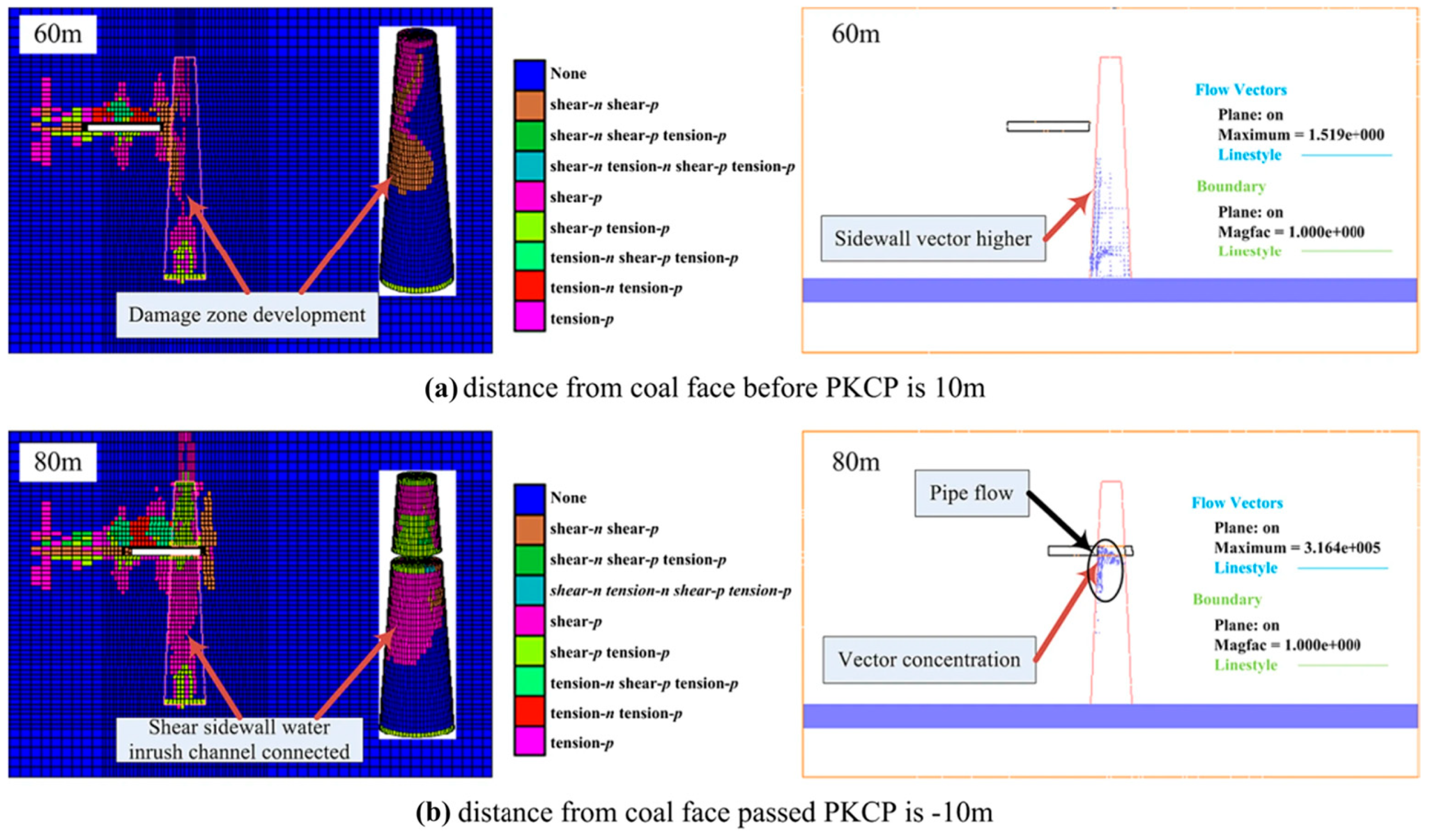
Figure 8: Damage zone and seepage vectors evolution when the working face is advanced before and after the penetrated KCP. Adapted with permission from Reference [106]. Copyright © 2022, Springer.
5.4.2 Long-Term Effects of Seepage Forces on Support Structures and Rock Mass Degradation
Seepage is not only an immediate mechanical threat but also a long-term, cumulative “chronic condition”. Its detrimental effects on engineering structures manifest primarily at two levels:
- Direct mechanical action—seepage force: Flowing groundwater exerts a “seepage force” on fracture walls and support structures, acting in the direction of flow. Under high hydraulic head gradients, this seepage force can reach the megapascal scale—sufficient to mobilize loose rock blocks, erode infill materials, and even exert sustained thrust on shotcrete linings or steel arches, leading to deformation, cracking, and potential instability of the support system [107].
- Indirect chemo-mechanical action—rock mass degradation: Long-term seepage accelerates the chemical weathering and mechanical deterioration of the surrounding rock. Groundwater dissolves cementing minerals (e.g., calcite, clay minerals), reducing rock strength and promoting fracture propagation. Simultaneously, the lubricating effect of water lowers the friction coefficient along fracture surfaces, weakening their shear resistance [108]. Experimental tests further confirm this mechanism: as illustrated in Fig. 9, the friction coefficient of basalt fractures shows a significant decreasing trend with the increase of pore water pressure, and this weakening effect is more pronounced in gouge-bearing fractures. Specifically, Fig. 9b (bare basalt fractures) and Fig. 9c (gouge-bearing basalt fractures) clearly demonstrate that pore water not only lubricates the fracture surface directly but also dissolves cementing minerals in the gouge, further reducing the shear resistance of the rock mass. This “water–rock–mechanics” degradation is slow and insidious, often remaining latent for years after construction before manifesting visibly—yet it can fundamentally undermine the long-term structural safety. Therefore, lifecycle management of tunnels must include continuous monitoring and assessment of seepage-induced corrosion effects.
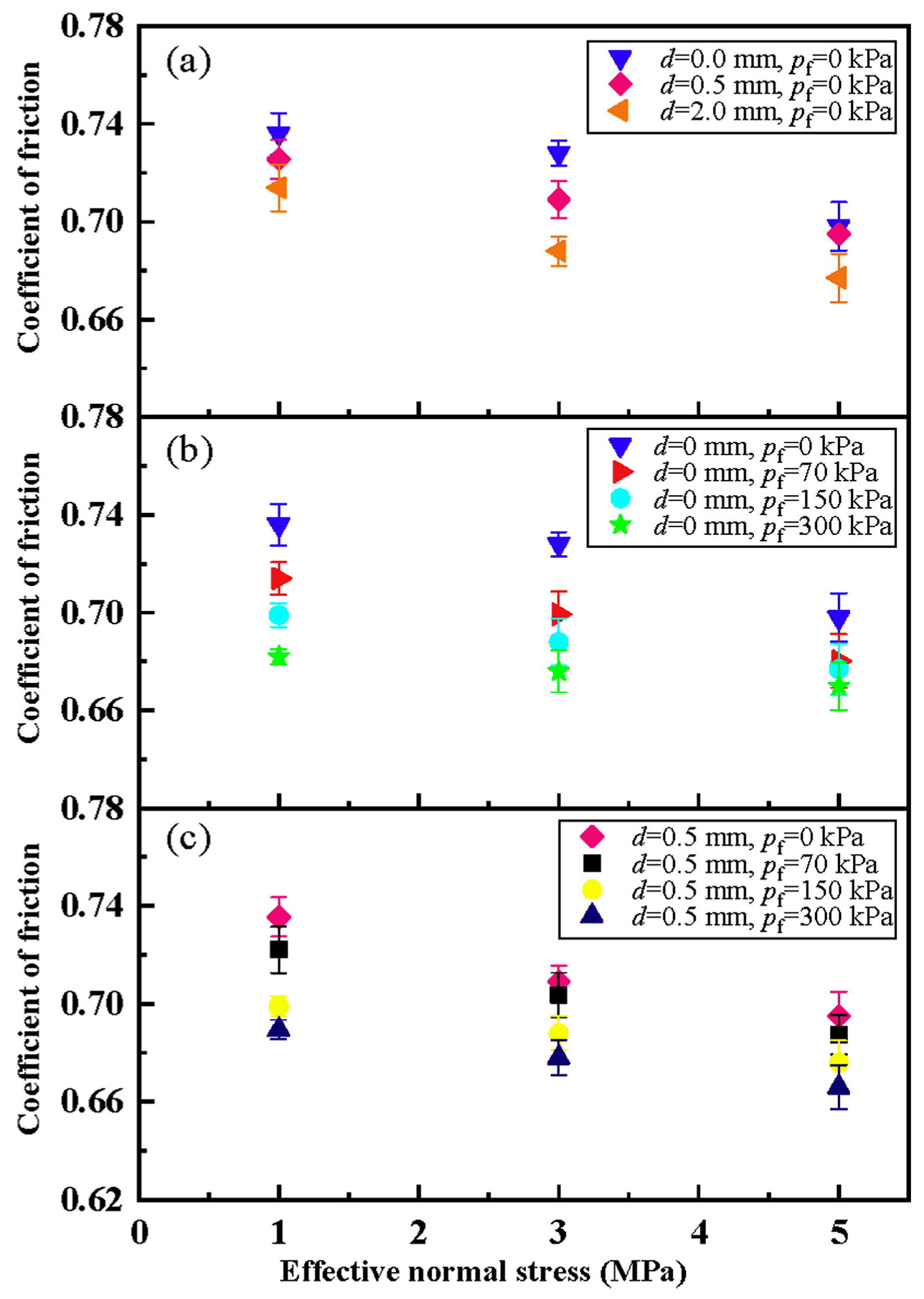
Figure 9: Variations in the friction coefficient with effective normal stress under various (a) Gouge layer thicknesses; (b) Pore pressures (bare basalt fractures); and (c) Pore pressures (gouge-bearing basalt fractures). The
5.4.3 Unique THM Challenges in Freeze Construction in Cold Regions
In water-rich weak strata or high-hydraulic-pressure zones, AGF is an effective temporary support technique. The method works by artificially refrigerating the ground to form a closed “frozen soil curtain” around the tunnel, leveraging the high strength and low permeability of frozen soil to isolate groundwater [110]. However, this approach transforms the original HM coupling problem into a far more complex THM three-field coupling challenge.
- The double-edged nature of frost heave pressure: Water expands by approximately 9% upon freezing, generating substantial frost heave pressure (up to several megapascals) in confined spaces [111]. This pressure can be harnessed beneficially to compact and densify the surrounding soil, thereby enhancing its mechanical strength. However, if not properly controlled, frost heave pressure can act adversely on support structures, causing lining cracks or deformation.
- Strong nonlinearity of the phase-change process: The advancement of the freezing front involves a highly nonlinear phase transition, accompanied by latent heat release, moisture migration, and ice lens formation. Minor changes in the temperature field (T) can trigger dramatic responses in the H and M fields. For instance, unfrozen water migrates toward the freezing front under thermal gradients, intensifying localized frost heave; meanwhile, ice formation directly alters the soil’s permeability and strength [112].
- Anisotropy and asymmetric deformation: Due to variations in geological conditions, refrigeration pipe layout, or groundwater flow, the temperature field within the frozen curtain is often non-uniform, resulting in pronounced anisotropy in both frozen soil strength and frost heave pressure. This leads to asymmetric stress and deformation distributions around the tunnel, imposing higher demands on support structure design. Numerical simulations show that neglecting this anisotropy can result in severe misestimation of structural loads.
- Cumulative damage from freeze-thaw cycles: During later construction stages or operational periods, thawing of the frozen curtain can induce thaw settlement. Repeated freeze-thaw cycles inflict cumulative damage on both the rock/soil mass and support structures, progressively degrading their strength and stiffness and continuously reducing the safety factor [113].
Therefore, the success of freeze construction critically depends on high-fidelity THM coupled models. Such models must be capable of simulating the entire process—including ice-water phase change, moisture migration, frost heave pressure generation, and stress redistribution—to provide a scientific basis for optimizing refrigeration schemes, designing support structures, and managing thaw-induced settlement risks [110]. This represents not only a technical challenge but also the ultimate test of multiphysics coupling theory’s predictive capability under extreme engineering conditions.
6 The Transformative Role of AI and ML
The rapid advancement of AI and ML is injecting a transformative force into the study of fluid flow and multiphysics coupling in fractured rock masses, accelerating a paradigm shift from traditional, physics-based deterministic modeling toward a new data-driven, pattern-recognition, and intelligent prediction framework [114]. At its core, this shift redefines the rock mass not as a set of partial differential equations to be solved, but as a complex data system rich in hidden information. By uncovering latent correlations and nonlinear patterns within data, AI/ML enables efficient and highly accurate prediction of system behavior [115].
The strength of this new paradigm lies in its powerful generalization capability and its ability to handle high-dimensional, heterogeneous data. Faced with the inherent strong heterogeneity, multiscale nature, and data sparsity of fractured rock masses, traditional physics-based models often rely on numerous simplifying assumptions. In contrast, AI/ML can directly learn complex input–output mappings from raw data—such as borehole images, geophysical logs, microseismic monitoring records, and digital rock cores—bypassing the need for explicit physical modeling and offering an “end-to-end” solution [116].
6.1.1 Typical Applications in Rock Engineering
- (1)Intelligent Rock Mass Classification and Prediction of Mechanical Parameters
Traditional rock mass classification systems (e.g., RMR, Q-system) heavily rely on expert judgment, making them subjective and inefficient [117]. AI/ML algorithms—such as Support Vector Machines (SVM), Random Forests (RF), and Artificial Neural Networks (ANN)—have been successfully applied to automate rock mass classification and enable rapid prediction of key mechanical parameters, such as uniaxial compressive strength (UCS) and elastic modulus [118]. For instance, by inputting image features from drill core samples or geophysical logging curves, these models can output rock mass mechanical properties within seconds, achieving accuracy comparable to laboratory testing and providing real-time, low-cost data support for engineering design.
- (2)Intelligent Permeability Prediction and Digital Rock Core Analysis
Permeability, as a core parameter in seepage analysis, is costly to measure directly and often lacks representativeness. AI/ML techniques—particularly three-dimensional convolutional neural networks (3D CNNs)—can now directly extract microstructural pore features from high-resolution digital rock images and predict macroscopic permeability within seconds, achieving speedups of several orders of magnitude compared to traditional methods such as the LBM or direct numerical simulation [119]. This breakthrough enables large-scale, high-precision reservoir property evaluation.
- (3)Intelligent Characterization and 3D Reconstruction of Fracture Networks
Accurate identification and geometric parameter extraction of fractures are fundamental to DFN modeling, yet traditional image segmentation methods often suffer from errors due to noise and complex backgrounds. Intelligent segmentation algorithms based on RF and deep learning can now identify fracture boundaries with high precision from complex 2D/3D images—such as CT scans or outcrop photographs—effectively overcoming the subjectivity of manual interpretation and the tendency of conventional algorithms to overestimate fracture aperture [120]. Moreover, AI models can integrate multisource data (e.g., seismic attributes, borehole imaging) to construct reservoir-scale 3D fracture intensity models, enabling a leap from “point” observations to “volumetric” characterization.
- (4)Hydraulic Fracturing and Production Forecasting
In oil/gas and geothermal engineering, predicting fracture geometry and production performance after hydraulic fracturing remains a central challenge. Purely physics-based models are limited by high computational costs and difficulty in capturing complex nonlinear behaviors. AI/ML models, by learning from vast historical fracturing datasets—including geological parameters, pumping schedules, microseismic events, and production data—can now predict fracture propagation patterns and ultimate productivity. This capability provides powerful real-time decision support for optimizing injection strategies in the field [121]. To further improve the generalization ability and computational efficiency of AI/ML models, parameter sensitivity analysis is critical for identifying key input factors and simplifying model structures. Fig. 10 presents the sensitivity analysis of two typical regression models (KRR and GPR), which quantifies the impact of core parameters (e.g., Young’s modulus, injection rate) on the prediction accuracy of fracture geometry. The results show that injection rate and closure stress are the most sensitive parameters for both models, providing a theoretical basis for feature selection in model optimization.
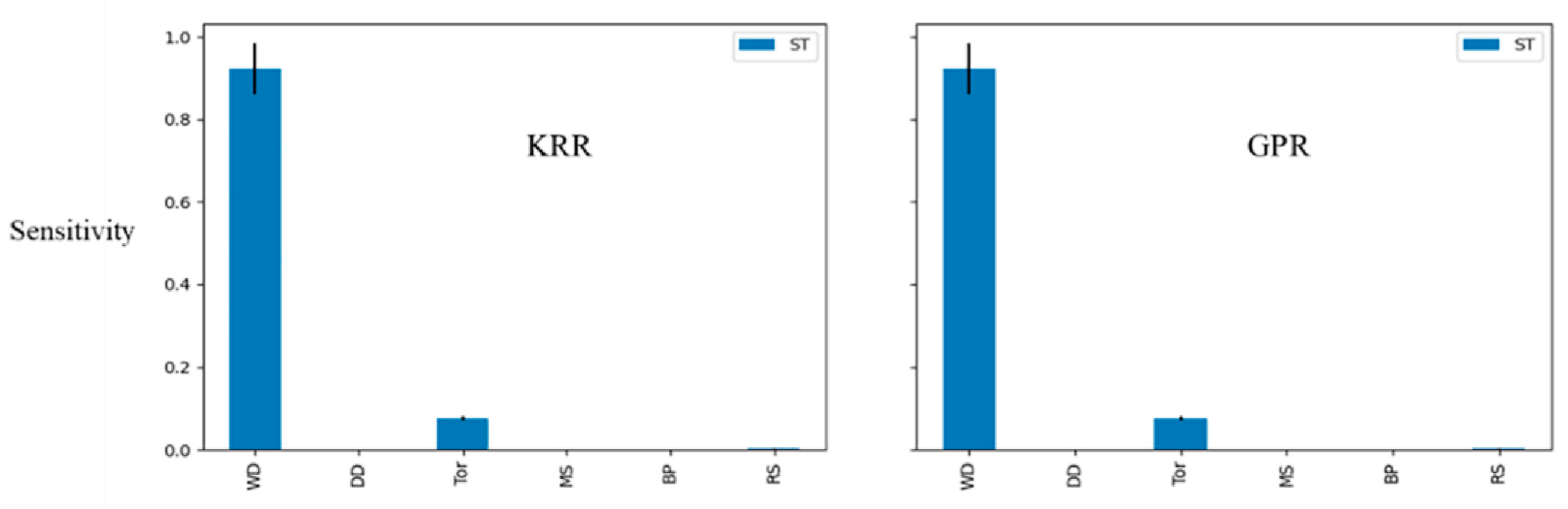
Figure 10: The sensitivity analysis of the KRR and GPR. Adapted with permission from Reference [122]. Copyright © 2025, Elsevier.
6.1.2 Maturity Assessment of AI/ML Methods in Practice
It is critical to distinguish between AI/ML approaches that have achieved engineering validation and those that remain emerging or experimental. Based on field deployment, reproducibility, and industry adoption:
- Widely validated methods include RF, SVM, and shallow ANNs. These have been successfully applied across multiple projects for rock mass classification, permeability estimation from logs, and production forecasting in conventional reservoirs [123]. Their robustness, interpretability (to some extent), and low data requirements make them suitable for routine engineering use.
- Emerging but promising methods include 3D Convolutional CNNs for digital rock physics, graph-based models for fracture network reconstruction, and physics-informed surrogates [124]. While they demonstrate high accuracy in research settings, their reliance on large, high-quality 3D datasets and limited field validation restrict current use to pilot studies or academic prototypes.
- Frontier research directions—such as Graph Neural Networks (GNNs) for dynamic DFN evolution or transformer-based models for spatiotemporal forecasting—remain largely conceptual [125], with few real-world demonstrations in deep subsurface environments due to data scarcity and computational complexity.
This tiered perspective ensures that practitioners can select appropriate tools based on project risk tolerance, data availability, and regulatory requirements—especially in safety-critical contexts like nuclear waste disposal or deep tunneling.
In summary, the AI/ML-driven paradigm is not intended to replace physics-based models but rather to serve as a powerful “accelerator” and “amplifier” for them. By automating and intelligently processing data and uncovering hidden patterns, AI/ML dramatically enhances the efficiency and accuracy of our understanding of complex geological systems. The applications listed in Table 6 offer innovative technical pathways to bridge the longstanding “data-model” gap that has challenged traditional approaches.
Nevertheless, it should be acknowledged that high-quality labeled data remain extremely scarce in deep underground engineering environments—often limited to sparse borehole measurements or indirect geophysical proxies. While few-shot learning and transfer learning offer promising avenues to mitigate data scarcity, their applicability hinges critically on the physical similarity between source and target domains. For instance, transferring a model trained on shallow sedimentary rock masses to deep crystalline fractured reservoirs may yield predictions with high confidence but poor physical fidelity, especially when key THMC coupling mechanisms differ significantly. To address this risk, future efforts should embed fundamental conservation laws as hard constraints within the transfer process and combine AI with active learning strategies to prioritize acquisition of informative field data under critical loading or injection conditions. Such safeguards are essential to ensure robustness and reliability when deploying AI in safety-critical subsurface applications.
Table 6: Core applications and technical approaches of AI/ML in fractured rock mass research.
| Application Domain | Core Task | Key AI/ML Techniques | Representative Achievements/Advantages |
|---|---|---|---|
| Intelligent Rock Mass Classification and Parameter Prediction | Rapid estimation of rock mass mechanical parameters (e.g., UCS, elastic modulus) | SVM, RF, ANN | Enables parameter prediction within seconds based on borehole images or logging data, with accuracy comparable to laboratory testing. |
| Permeability Prediction and Digital Rock Core Analysis | Direct prediction of macroscopic permeability from microscale images | 3D CNN | Prediction speed is orders of magnitude faster than LBM or direct numerical simulation, enabling large-scale reservoir property evaluation. |
| Intelligent Characterization of Fracture Networks | High-precision identification, segmentation of fractures from images, and 3D network reconstruction | RF, deep learning-based segmentation algorithms | Overcomes the overestimation of fracture aperture inherent in traditional methods, improving the accuracy of input data for DFN models. |
| Hydraulic Fracturing and Production Forecasting | Prediction of post-fracturing fracture geometry and oil/gas or geothermal production | Deep Neural Network (DNN) surrogate models | Achieves prediction accuracy >90% with a single prediction taking less than 10 s, enabling real-time optimization of injection strategies in the field. |
| Physics-Informed Modeling | Solving complex THMC-coupled partial differential equations while ensuring physical consistency | PINNs | Mesh-free solution with embedded physical laws, suitable for complex geometries and strongly nonlinear problems. |
| Hybrid Modeling and Parameter Inversion | Learning the residual between physics-based models and observational data to dynamically correct model parameters | Bayesian Neural Networks (BNNs), Gaussian Process Regression (GPR) | Improves prediction accuracy under data-sparse conditions, quantifies uncertainty, and supports data assimilation. |
6.2 Frontiers in Physics-Informed and Hybrid Modeling
Although purely data-driven AI/ML models demonstrate remarkable capabilities in prediction speed and pattern recognition, their “black-box” nature and lack of physical consistency remain fundamental barriers to widespread adoption in high-risk engineering applications. To bridge the gap between data-driven and physics-driven paradigms, two cutting-edge approaches have emerged: PINNs and Hybrid Modeling. These represent a profound shift in AI—from empirical fitting toward physics-embedded learning [126].
6.2.1 PINNs: Embedding Physical Laws into Neural Networks
The core innovation of PINNs lies in treating physical laws not as external constraints, but as intrinsic, inviolable rules directly embedded into the neural network’s loss function. Specifically, the loss function of a PINN consists of two components: (1) a data-fitting term (e.g., mean squared error between observations and network predictions), and (2) a physics residual term (i.e., the residual obtained when the network’s output is substituted into the governing partial differential equations, or (PDEs) partial differential equations). By minimizing the total loss, PINNs simultaneously fit the available data and enforce the solution to satisfy fundamental physical conservation laws—such as mass, momentum, and energy conservation—as well as constitutive relationships.
The core advantages of PINNs lie in:
- Guaranteed physical consistency: Model predictions inherently satisfy physical laws, eliminating non-physical solutions that may arise from purely data-driven approaches, thereby significantly enhancing result credibility and extrapolation capability.
- Mesh-free solution: PINNs do not require discretization of the solution domain into a mesh, thereby fundamentally avoiding the mesh distortion and remeshing challenges that plague traditional numerical methods (e.g., FEM) when handling complex geometries—such as rough fractures or moving boundaries—making them particularly well-suited for strongly discontinuous media like fractured rock masses.
- Data efficiency: By leveraging physical laws as strong prior knowledge, PINNs can produce physically plausible solutions even when observational data are sparse or noisy, significantly reducing reliance on large volumes of high-quality training data.
- High-dimensional and inverse problem solving: PINNs demonstrate unique advantages in handling high-dimensional parameter spaces and solving inverse problems—such as inferring permeability or stress fields from observational data—as their framework naturally supports the simultaneous optimization of state variables and unknown parameters.
6.2.2 Challenges in Enforcing Discontinuities at Fracture Intersections
Despite their theoretical suitability for fractured media, the practical implementation of PINNs faces significant challenges when handling discontinuous flow fields at fracture intersections, where hydraulic head gradients and fluxes can change abruptly due to mismatched transmissivity, aperture heterogeneity, or contact resistance. Standard PINN formulations assume sufficient smoothness of the solution to compute PDE residuals via automatic differentiation—a requirement violated at geometric singularities such as triple junctions or crossing fractures.
To embed such discontinuous interface conditions into the loss function, a common strategy is to explicitly enforce mass conservation and head compatibility at intersection points as soft constraints. Consider two fractures
These conditions are incorporated into the total loss as penalty terms:
These capabilities have been concretely demonstrated in a recent study by Liu et al. [127], who developed an Enriched Physics-Informed Neural Network (E-PINN) specifically for simulating two-phase flow in heterogeneous and fractured porous media—a problem long considered challenging for standard PINNs due to sharp property contrasts and interface discontinuities. To rigorously enforce flux continuity across fracture-matrix interfaces, the authors integrated the Embedded Discrete Fracture Model (EDFM) and replaced automatic differentiation with a finite volume method (FVM) to construct the physics-informed loss, ensuring accurate treatment of conservation laws at material boundaries. Their architecture further incorporates adjacency-aware anchoring, adaptive activation functions, and hard enforcement of initial/boundary conditions, significantly improving training stability and solution accuracy. Validated on 2D and 3D immiscible displacement problems in complex fractured reservoirs, this work provides a robust, mesh-free framework that directly addresses the geometric and physical complexities inherent in fractured rock masses—even under sparse data conditions.
To enhance the training stability and efficiency of PINNs, cutting-edge research has developed several advanced techniques, such as Exponential Moving Average (EMA) for weight stabilization, Residual-based Adaptive Refinement with Distribution (RAR-D) for intelligent sampling, and Bayesian optimization to automatically balance the weights between the physics residual and data-fitting terms [128]. In the context of fracture evolution in rock mechanics, strategies like transfer learning have also been introduced to avoid retraining the network from scratch at each loading step, thereby significantly improving computational efficiency.
6.2.3 Hybrid Models: Synergistic Co-Evolution of Data-Driven and Physics-Driven Approaches
If PINNs embed physical laws within the neural network, hybrid models achieve strategic synergy between data-driven and physics-driven approaches at the system architecture level. The core idea is to use a physics-based model to generate a reliable, interpretable baseline prediction, and then employ a data-driven model (e.g., a neural network) to learn the residual—or the mapping—between the physics-based prediction and real-world observations. This compensates for biases introduced by simplifying assumptions or parameter uncertainties inherent in the physical model.
Typical hybrid frameworks include:
- Low-fidelity physics-based model + high-fidelity data-driven corrector: For example, a computationally efficient ECM is used for preliminary simulation, and a neural network is then trained on the ECM’s inputs and outputs together with field monitoring data to learn the nonlinear patterns of the ECM’s prediction errors. The final prediction is given by “ECM output + neural network correction”, significantly improving accuracy while preserving physical interpretability [129].
- Physics-guided AI surrogates: Outputs from physics-based models (e.g., stress fields, temperature fields) are used as input features for AI models, guiding them to learn more complex, implicit relationships that the physics-based model cannot directly capture—such as the correlation between microseismic events and permeability evolution.
- Multiscale hybrid simulation: Physics-based models are employed at the macroscale, while data-driven models (e.g., CNNs for predicting local permeability) are used at micro- or mesoscales. Cross-scale coupling enables an optimal balance between computational efficiency and local accuracy.
The greatest value of hybrid models lies in their unification of robustness and interpretability. They inherit the strengths of physics-based models in mechanistic understanding and reliable long-term extrapolation, while simultaneously harnessing the power of AI models to handle high-dimensional, nonlinear, and heterogeneous data. This synergistic “1 + 1 > 2” effect makes hybrid modeling the most promising paradigm for tackling the extreme complexity of multiphysics coupling in fractured rock masses.
In summary, PINNs and hybrid models represent the most advanced form of AI for Science in geotechnical engineering. They do not seek to overturn traditional methods but rather to revolutionize and augment their capabilities. In the future, as algorithms continue to mature and computational power grows, physics-informed and hybrid modeling will inevitably transition from cutting-edge research to the core of engineering practice, laying a solid foundation for the next generation of intelligent rock mechanics models—ones that are interpretable, trustworthy, and capable of reliable extrapolation [130].
6.3 Comparative Analysis of AI/ML and Traditional Methods
The rise of AI and ML is not aimed at overturning or replacing traditional physics-based numerical simulation methods, but rather at providing a powerful complementary and enhancing tool. In the study of fluid flow and multiphysics coupling in fractured rock masses, AI/ML and traditional methods (e.g., FEM, DEM, DFN) each possess distinct strengths and limitations. Their true value lies not in competition, but in strategic integration—leveraging their complementary advantages to jointly tackle complex engineering challenges that neither approach can resolve alone [131]. Table 7 presents a systematic comparison between the two across multiple key dimensions.
Table 7: Comparative analysis of AI/ML and traditional numerical methods in fractured rock mass research.
| Evaluation Dimension | AI/ML Approaches | Traditional Numerical Methods |
|---|---|---|
| Computational Efficiency | Extremely high during inference: once trained, models can generate predictions in milliseconds to seconds, enabling real-time decision-making. | High computational cost: solving complex nonlinear systems of partial differential equations is extremely time-consuming, especially for large-scale models. |
| Data Requirements | Reliant on large volumes of high-quality data: model performance is highly dependent on the quantity, quality, and diversity of training data. | Reliant on accurate physical parameters: requires precise constitutive parameters, boundary conditions, and initial conditions. |
| Handling of Heterogeneity | Significant advantage: excels at automatically extracting complex patterns and correlations from high-dimensional, unstructured, and highly heterogeneous data. | Challenging: heterogeneity must be addressed through stochastic modeling or highly refined mesh discretization, which drastically increases computational cost. |
| Physical Consistency | Potential weakness: purely data-driven models may produce non-physical solutions; this can be mitigated by embedding physical laws, as in PINNs. | Core strength: grounded in first principles, results inherently satisfy physical laws and exhibit intrinsic consistency. |
| Interpretability | “Black-box” nature: complex models such as deep learning offer limited transparency in their decision-making process, making it difficult to provide explanations at the level of underlying physical mechanisms. | Highly interpretable: governing equations and solution procedures are clear and transparent, allowing direct tracing of the evolution of physical quantities. |
| Applicable Scenarios | Rapid prediction, pattern recognition, classification, surrogate modeling, big data mining, real-time monitoring, and early warning. | Mechanistic studies, process simulation, long-term evolution prediction, safety assessment of high-risk engineering projects, and in-depth analysis of physical mechanisms. |
As shown in the table above, AI/ML and traditional methods are fundamentally complementary rather than mutually exclusive. The “speed” and “data-driven” strengths of AI/ML precisely address the “computational slowness” and “parameter dependency” limitations of traditional methods, while the “physical consistency” and “interpretability” of traditional approaches provide essential constraints and validation benchmarks for the “black-box” nature of AI/ML.
Future research and engineering practice will increasingly adopt the following synergistic strategies:
- (1)AI as an “accelerator” for traditional models: Train AI models as surrogate models for computationally expensive physics-based simulations. For example, a neural network can replace time-consuming DFN or THMC coupled simulations to enable second-level parameter sensitivity analysis or real-time optimization, while the physics-based model is reserved for validation and calibration in critical scenarios.
- (2)Traditional models provide “physical constraints” for AI: Embed physical laws into AI training (e.g., via PINNs) or use outputs from physics-based models as input features for AI, ensuring the physical plausibility of AI predictions and enhancing their generalization capability in data-sparse regions.
- (3)Hybrid modeling frameworks: Construct an integrated architecture combining a “physics-based model + AI corrector”. The physics-based model provides a baseline prediction, while the AI component learns the residual between this baseline and real-world observations, thereby significantly improving predictive accuracy while preserving physical interpretability.
- (4)AI-driven data assimilation and parameter inversion: Leverage AI’s powerful pattern recognition capabilities to efficiently invert key subsurface parameters—such as permeability and stress fields—from sparse, noisy field monitoring data (e.g., microseismic events, temperature, pressure), thereby providing more accurate inputs for traditional physics-based models.
In summary, the integration of AI/ML with traditional numerical methods represents an evolution in fractured rock mass research—from reliance on a “single tool” to the deployment of an “intelligent toolchain”. Table 8 clearly illustrates the respective strengths and weaknesses of AI/ML and traditional approaches, offering an intuitive basis for understanding their complementary relationship. Future breakthroughs will no longer hinge on the extreme advancement of any single method, but on how skillfully we weave this synergistic “physics + data” network to achieve an unprecedented balance among computational efficiency, predictive accuracy, physical robustness, and engineering practicality. This is not merely a choice of technical pathway, but a profound transformation in research paradigm [132].
Table 8: Strategies of AI/ML for addressing core challenges in fractured rock mass research.
| Core Challenge | AI/ML Response Strategy | Key Technologies and Expected Benefits |
|---|---|---|
| Data Scarcity and Quality Bottleneck | Synthetic data generation and data augmentation | Use Generative Adversarial Networks (GANs) or Variational Autoencoders (VAEs) to generate synthetic fracture networks that conform to geostatistical rules, thereby expanding training datasets and enhancing model robustness. |
| Multisource heterogeneous data fusion | Integrate seismic attributes, well logs, remote sensing imagery, and laboratory data to train multimodal AI models that extract meaningful information from “soft data.” | |
| Model “Black Box” and Lack of Interpretability | Developing Explainable Artificial Intelligence (XAI) | Apply XAI techniques such as SHAP and LIME to visualize the decision pathways of AI models, providing engineers with physically interpretable insights and enhancing trust in model predictions. |
| Constructing physics-informed hybrid models | Adopt a “physics-based model + AI corrector” architecture that maintains physical interpretability while leveraging AI to learn complex residuals, thereby unifying high accuracy with transparency. | |
| Computational Cost and Efficiency Bottleneck | Developing AI surrogate models | Replace time-consuming physics-based simulations (e.g., DFN, LBM) with neural networks, reducing single simulation time from hours to seconds and enabling real-time optimization and uncertainty quantification. |
| AI-driven solver acceleration | Employ GNNs to design intelligent preconditioners, or apply reinforcement learning (RL) to optimize time-stepping strategies, significantly enhancing the convergence speed and stability of traditional solvers. | |
| Complex Networks and Multiscale Characterization | Intelligent inverse modeling and parameter inversion | Train DNNs on monitoring data—such as microseismic events, temperature, and pressure—to invert the geometry of subsurface fracture networks and permeability fields, enabling an intelligent leap from “observations” to “models”. |
| Cross-scale correlation modeling | Use deep learning to establish mapping relationships between microscopic pore characteristics and macroscopic equivalent parameters (e.g., permeability, modulus), providing a data-driven bridge for multiscale simulations. | |
| Weak Model Generalization and Extrapolation Capability | PINNs | Enforce compliance with governing equations in the loss function to ensure the model produces physically consistent solutions even in data-sparse regions or extrapolation scenarios, thereby enhancing prediction reliability. |
6.4 Embedding AI into Traditional Simulation Workflows: Practical Integration Pathways for Engineering Applications
While the complementary nature of AI/ML and traditional numerical methods has been widely acknowledged, a critical gap remains between theoretical synergy and practical implementation in real-world engineering projects. To bridge this gap, it is essential to move beyond conceptual comparisons and articulate concrete, actionable strategies for mbedding AI modules into established simulation workflows—such as those based on FEM, DFN, or dual-porosity models—without disrupting existing engineering practices.
Three pragmatic integration pathways have emerged as particularly viable for field deployment:
- (1)AI as a Plug-in Surrogate for Bottleneck Components
Identify computationally intensive subroutines within a traditional workflow (e.g., fracture network flow solver, THMC coupling loop, or parameter sensitivity analysis) and replace them with pre-trained AI surrogates. For instance, a 3D CNN trained on LBM simulations of digital rock cores can instantly predict permeability tensors [133], which are then fed into a reservoir-scale DFN model. This “swap-and-run” approach requires minimal modification to legacy code and delivers orders-of-magnitude speedup while preserving the overall workflow structure.
- (2)AI-Augmented Physics-Based Simulators via Residual Learning
In this hybrid architecture, the physics-based simulator runs as usual to generate a baseline prediction (e.g., pore pressure evolution during tunnel excavation). A lightweight neural network—trained on historical monitoring data (e.g., piezometer readings, extensometer displacements)—learns the residual error between simulation and reality [134]. The final output is the sum of the physics-based prediction and the AI correction. This strategy compensates for model simplifications (e.g., homogenized fracture properties) without sacrificing interpretability, making it suitable for safety-critical applications like dam foundation seepage analysis.
- (3)AI-Driven Real-Time Data Assimilation Loops
Integrate streaming field data (e.g., from fiber-optic DTS/DAS, microseismic arrays, or IoT sensors) into the simulation cycle via AI-enabled inversion. For example, a BNN can continuously update fracture aperture distributions in a DFN model using real-time pressure transients [135], effectively creating a “digital twin” of the subsurface system. This closed-loop framework transforms static simulations into dynamic, adaptive decision-support tools—critical for operations such as EGS reservoir management or CO2 injection monitoring.
Key Enablers and Implementation Considerations:
- Modular software design: Adoption hinges on simulation platforms (e.g., OpenGeoSys, TOUGH–FLAC3D, COMSOL) supporting external AI calls via APIs or co-simulation interfaces.
- Uncertainty quantification: Techniques like Monte Carlo dropout or ensemble methods should be integrated to propagate AI prediction uncertainty into final engineering decisions.
- Data curation pipelines: Field engineers need standardized protocols to convert raw sensor logs into AI-ready features (e.g., time-series embeddings, spatial statistics).
These integration pathways demonstrate that AI does not require a “rip-and-replace” overhaul of existing workflows. Instead, it can be incrementally embedded as intelligent, task-specific modules—enhancing accuracy, speed, and adaptability while respecting the institutional knowledge and validation standards embedded in traditional geomechanical practice.
7 Core Challenges and Future Research Directions
The profound scale-dependent discrepancies between laboratory measurements and field-scale behavior constitute a primary motivation for the development of advanced multiscale modeling frameworks. As shown, key hydraulic and mechanical parameters (e.g., permeability, reaction rates) measured on centimeter-scale rock cores often deviate by orders of magnitude from their in-situ counterparts due to the irreducible complexity of natural fracture networks [136], geological history, and boundary conditions at engineering scales. This “scale gap” renders single-scale models inherently unreliable for field prediction [137]. Consequently, the multiscale coupled modeling strategies discussed in this section are not merely theoretical refinements; they represent a necessary paradigm shift to bridge the chasm between controlled laboratory physics and real-world fractured rock systems.
7.1 Multiscale Coupled Modeling
One of the most fundamental challenges in the study of fluid flow and multiphysics coupling in fractured rock masses is bridging the vast gap between microscopic pore/fracture scales and macroscopic engineering/geological scales [138]. The macroscopic behavior of rock masses is not a simple summation of its components but an emergent property arising from the collective evolution of millions of microscopic physical processes—such as non-Darcy flow, fluid–rock reactions, and fracture wall contact mechanics—under complex geometric constraints. While current mainstream models have matured significantly at individual scales, the core bottleneck limiting predictive accuracy and generalizability remains the lack of a theoretical framework that seamlessly links physical mechanisms across scales and enables a consistent transfer from “microscale mechanisms” to “macroscale responses” [139].
7.1.1 Decoupling between Microscale Mechanisms and Macroscale Behavior
At the microscale (micrometer to millimeter scale), fluid flow through rough fractures has long deviated from the classical linear Darcy’s law, exhibiting non-Darcy characteristics dominated by inertial effects. Flow patterns include vortices, recirculation zones, and high-velocity jets—complex phenomena that require nonlinear models such as the Forchheimer equation for accurate description [140]. Simultaneously, water–rock chemical reactions (dissolution/precipitation) at mineral surfaces proceed slowly at molecular diffusion rates, yet they irreversibly alter fracture geometry, ultimately governing the long-term permeability and mechanical strength of the rock mass at the macroscale. However, in engineering-scale (meter to kilometer) numerical models, these microscale processes are typically either highly parameterized or entirely neglected. For instance, the permeability tensor in ECMs functions as a “black-box” parameter, disconnected from its underlying microscale physical origins. Similarly, while the “shape factor” in dual-porosity models attempts to characterize matrix–fracture exchange, its physical definition remains ambiguous—particularly for sparse fracture networks [141].
This scale disconnect leads to systematic biases in model predictions. Reaction rates or permeability parameters measured in the laboratory often differ by orders of magnitude when extrapolated to field scales. The root cause lies in the inability of macroscopic models to capture the nonlinear cumulative effects of microscale mechanisms and the amplification of spatial heterogeneity across scales.
7.1.2 Building Scale Bridges: Homogenization Techniques and Nested Coupling Strategies
To bridge this gap, future research must move beyond simplistic “scaling-up” approaches and develop cross-scale modeling methods capable of faithfully transferring physical mechanisms across scales. Two cutting-edge directions hold particular promise:
- (1)Advanced Homogenization Techniques: Traditional homogenization methods (e.g., volume averaging) often fail when applied to strongly heterogeneous and discontinuous media. Next-generation homogenization theories must accommodate nonlinear constitutive relationships and dynamic boundary conditions. For instance, the multiscale FEM, based on Representative Volume Elements (RVEs), embeds a microscale RVE model at each macroscopic integration point to compute local nonlinear responses—such as stress-induced permeability changes—in real time. The homogenized results are then fed back into the macroscale model [142]. This approach enables microscopic physical laws—such as Forchheimer flow or chemical reaction kinetics—to be explicitly embedded into macroscopic governing equations in the form of constitutive relationships, thereby achieving faithful transfer of physical mechanisms across scales.
- (2)Nested Coupling Strategies: This approach acknowledges that different physical processes dominate at different scales and employs scale-appropriate models in different regions, dynamically exchanging data to achieve coupling. For example, in the near-wellbore stimulation zone of an EGS, a high-fidelity DFN model or LBM can be used to simulate microscale fracture dilation and non-Darcy flow; in the far-field reservoir, a computationally efficient dual-porosity model suffices. The two domains are bidirectionally coupled through shared boundary conditions—such as pressure, flow rate, and temperature. This “local high-fidelity + global efficiency” architecture captures critical physical details where they matter most while maintaining manageable overall computational cost, making it an ideal solution for large-scale, multiscale engineering problems.
Moreover, data-driven cross-scale correlation models are emerging as a powerful new tool. By leveraging ML—particularly DNNs—these models can directly learn the complex, nonlinear mapping between microscale features (e.g., porosity distribution, fracture roughness) and macroscale effective properties (e.g., equivalent permeability, elastic modulus) from large datasets of microscale simulations or high-resolution digital rock images [143]. Unlike traditional approaches, this method does not rely on explicit physical derivation; instead, it efficiently constructs an “empirical bridge” across scales, making it especially valuable for complex systems where underlying physical mechanisms remain poorly understood.
In summary, the future of multiscale coupled modeling does not lie in pursuing a single “universal” model, but in developing a flexible, open, and integrative multiscale collaborative framework [144]. Such a framework should be capable of intelligently selecting and coupling sub-models at appropriate scales based on the specific problem at hand, ensuring that microscale physical mechanisms are faithfully reflected in macroscale predictions. Only through this approach can we achieve a true cognitive leap—from “seeing a single tree” to “understanding the entire forest”—and lay a robust scientific foundation for the safety and efficiency of deep Earth engineering.
7.2 Model and Parameter Uncertainty
In the study of multiphysics coupling in fractured rock masses, the reliability of model predictions is fundamentally constrained by the accuracy of input parameters. However, obtaining high-fidelity THMC coupling parameters—especially under the extreme conditions typical of deep subsurface environments, such as high temperature, high pressure, and strong chemical corrosivity—represents one of the most severe technical bottlenecks in the field today [145]. This parameter uncertainty is not merely a matter of measurement error; rather, it arises from the combined effects of physical complexity, limitations of experimental techniques, and scale-dependent phenomena. Consequently, it creates a persistent and often irreducible gap between numerical simulations and field observations.
7.2.1 Inherent Difficulties in Parameter Acquisition under High Temperature and High Pressure
Deep rock masses—such as those in EGS reservoirs or host rocks surrounding nuclear waste repositories—typically exist under extreme conditions of several hundred degrees Celsius and tens of megapascals of pressure. Under such harsh thermo-hydro-chemical environments, the constitutive relationships between rock and fluid exhibit strong nonlinearity and path dependence. For example:
- Stress sensitivity of permeability: Under high in-situ stress, fracture closure and shear dilation exhibit highly nonlinear behavior that is strongly dependent on stress history. Conventional laboratory triaxial tests struggle to replicate the complex in-situ stress paths, causing laboratory-derived stress-permeability relationships to fail when extrapolated to field condition [146].
- Temperature dependence of thermal properties: Parameters such as rock thermal conductivity, thermal expansion coefficient, and fluid viscosity and density vary significantly with temperature. In high-temperature zones above 200°C, even minor errors in these parameters can be exponentially amplified through the THM coupling chain, leading to substantial deviations in predicted thermal recovery efficiency or temperature field distribution from actual field behavior [147].
- Scale effects in chemical reaction rates: Mineral dissolution/precipitation rates measured in the laboratory are typically obtained under idealized conditions. At the field scale, however, these rates are strongly controlled by fluid transport, fracture geometry, and mineral spatial distribution, often resulting in discrepancies of several orders of magnitude compared to laboratory values [148].
More critically, many key parameters—such as fracture surface friction coefficient, Biot-Willis coefficient
7.2.2 Urgent Need for High-Fidelity In Situ Experiments and Extreme-Environment Sensing Technologies
To overcome this bottleneck, the research focus must shift from “relying on laboratory calibration” to “developing in situ validation capabilities”. Currently, there is an urgent demand for the following two types of technologies:
- (1)High-Fidelity In Situ Coupled Experimentation Techniques:
Current laboratory equipment is mostly designed for single physical fields or mild conditions, making it inadequate for replicating the true multiphysics environments found in EGS or nuclear waste repositories. There is an urgent need to develop next-generation, field-scale physical simulation platforms capable of simultaneously applying high temperature, high pressure, reactive fluids, and mechanical perturbations under controlled conditions to directly observe the dynamic response of fracture networks under coupled THMC processes [150]. For instance, a large-scale true-triaxial seepage–thermal–mechanical coupled testing system could simulate the combined effects of kilometer-scale in-situ stress fields and thermal pulses, providing the most field-representative validation benchmark for numerical models.
- (2)Intelligent Sensing and Monitoring Technologies for Extreme Environments:
Direct field measurement is the ultimate means to reduce parameter uncertainty, yet current sensors commonly suffer from short lifespans, low accuracy, and frequent failure under deep subsurface high-temperature and high-pressure conditions. Future research must deeply integrate with materials science and microelectronics to develop a new generation of intelligent sensors capable of withstanding extreme environments:
- Distributed fiber-optic sensing: Based on Brillouin or Raman scattering principles, this technology enables continuous, real-time monitoring of temperature, strain, and pore pressure along boreholes or tunnels, with spatial resolution down to the meter scale. It is passive, immune to electromagnetic interference, and highly durable in harsh environments.
- Nanofunctional material-based sensors: Examples include temperature-sensitive quantum dots or piezoelectric nanoparticles that can be injected into fracture networks. These nanoscale probes enable in situ monitoring by remotely detecting their response signals to infer local physical fields—effectively acting as “microscopic sensors” embedded directly within the rock matrix.
- Self-powered and wireless transmission technologies: Address the critical challenges of power supply and data retrieval for deep subsurface sensors, enabling long-term, real-time, and unattended monitoring.
- Furthermore, data assimilation techniques will serve as the critical link between field monitoring and numerical modeling. By continuously integrating sparse and noisy field observations—such as microseismic events, temperature, and pressure—into numerical models in real time, data assimilation dynamically updates model parameters and state variables. This significantly reduces predictive uncertainty and enables a paradigm shift from “open-loop simulation” to “closed-loop forecasting” [151].
In summary, model and parameter uncertainty remains the central obstacle preventing fractured rock multiphysics coupling research from advancing from qualitative understanding to quantitative prediction [152]. Overcoming this challenge cannot rely solely on algorithmic improvements; it demands a dual-driven approach combining experimental innovation and sensing technology breakthroughs. A unified, four-in-one parameter calibration and validation framework—integrating laboratory experiments, in situ testing, field monitoring, and data assimilation—must be established. Only through such an integrated system can we provide truly reliable scientific foundations for the safe design and risk management of deep Earth engineering projects [153].
7.3 Characterization of Complex Fracture Networks
The core challenge in accurately modeling natural fractured rock masses lies in realistically and efficiently characterizing their inherent high degree of randomness, complex three-dimensional topological structure, and multi-fracture intersection characteristics. These geological features are not mere geometric details—they are decisive factors that directly control fluid flow pathways, solute transport efficiency, and mechanical stability. Current mainstream modeling approaches universally encounter theoretical bottlenecks and computational difficulties when dealing with such complexity, creating an urgent need for next-generation intelligent algorithms to overcome the dual constraints of representation accuracy and computational efficiency.
7.3.1 Modeling Challenges Posed by Stochasticity, 3D Topology, and Fracture Intersections
Natural fracture networks form complex systems comprising randomly interweaving fractures of diverse scales, orientations, and densities in three-dimensional space. The stochastic nature of their 3D topology is illustrated in Fig. 11 through a comparison between measured fracture traces and simulated ones; the simulated traces are generated by intersecting a sampling window with a 3D stochastic discontinuity model. This correspondence between field observations and numerical simulations not only validates the rationality of the stochastic modeling approach—the primary modeling challenges arise in three key aspects:
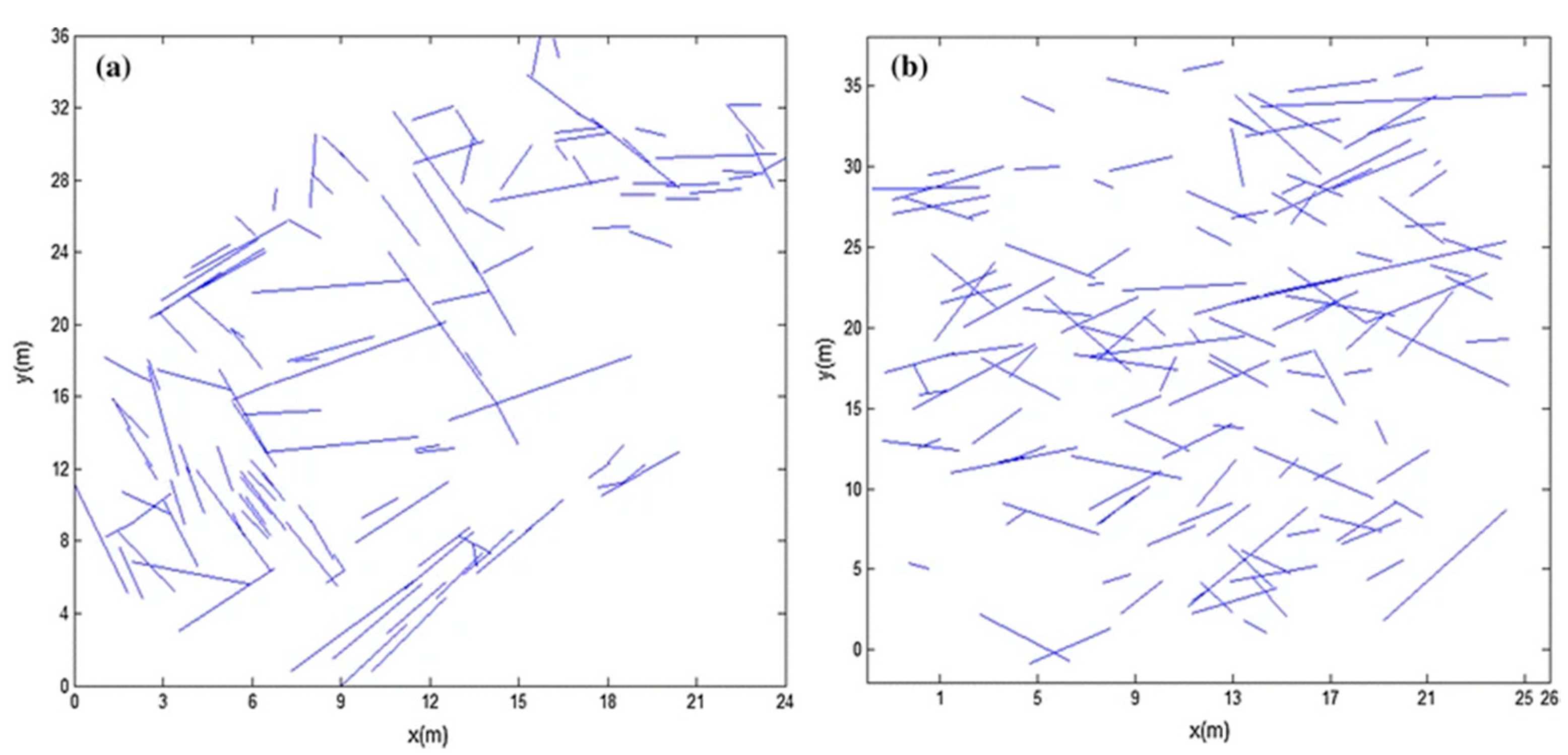
Figure 11: Comparison between measured traces and numerical model. (a) In-situ measured discontinuities traces. (b) Simulated traces formed by intersection between sampling window and stochastic model. Adapted with permission from Reference [154]. Copyright © 2015, Springer.
- (1)Geometric stochasticity and statistical characterization: Fracture parameters—such as location, size, aperture, and roughness—follow specific probability distributions (e.g., power-law or log-normal distributions). Although DFN models can generate stochastic networks via Monte Carlo methods, the calibration of their statistical parameters (e.g., fracture density, mean aperture) heavily relies on sparse and costly field data—such as borehole imaging or outcrop mapping. Uncertainty in these data propagates directly into the model, resulting in large variances in simulation outcomes and limiting their applicability for deterministic safety assessments in high-risk engineering projects [155].
- (2)Three-dimensional topological connectivity: The connectivity of fractures in 3D space is the key determinant of the “channeling effect”. An isolated fracture contributes negligibly to global flow, whereas a connected pathway formed by intersecting fractures can carry over 90% of the total fluid flux. Traditional DFN models often fail during mesh generation when handling 3D fracture intersections—either due to geometric conflicts or the creation of severely distorted elements—compromising both computational stability and accuracy.
- (3)Physical modeling of fracture intersections: At fracture intersection points, fluid flow and mechanical behavior undergo dramatic changes. The classical cubic law breaks down, and flow exhibits strong three-dimensional vortices and significant pressure losses. Simultaneously, stress concentration at these junctions greatly increases the likelihood of new fracturing or shear slip. Current models typically simplify intersections as “nodes” and approximate their hydraulic behavior using empirical “intersection rules” or “transfer coefficients”, which lack a solid physical basis and constitute a major source of predictive uncertainty in numerical simulations.
These challenges give rise to a fundamental contradiction: although DFN models can, in principle, represent fracture networks with the highest fidelity, their high computational cost and demanding data requirements make them impractical for large-scale engineering applications. Conversely, while ECM or dual-porosity models offer computational efficiency, their excessive geometric simplifications prevent them from capturing critical localized flow pathways [156].
7.3.2 ML: Solving Inverse Modeling and Parameter Constraint Challenges
ML, particularly DNNs, offers a revolutionary approach to addressing the aforementioned characterization challenges. Its core value lies in the ability to automatically learn the complex, nonlinear mapping between fracture network geometric features and macroscopic system responses—such as pressure, temperature, and microseismic signals—from sparse and noisy observational data, thereby enabling efficient inverse modeling and parameter constraint.
- (1)Inverting fracture networks from observational data: Traditional inversion methods—such as trial-and-error or optimization algorithms—suffer from exponentially increasing computational costs and a tendency to converge to local optima when dealing with high-dimensional parameter spaces (involving tens of thousands of fracture parameters). In contrast, DNNs can establish an end-to-end mapping from “observational data → fracture network parameters” through supervised learning [157]. For instance, Fig. 12 illustrates the complex dynamic evolution of fracture networks captured by high-resolution CT scanning. Such image sequences contain rich information regarding pore structure and geometric topology, presenting a significant challenge for traditional manual interpretation or simple segmentation methods to accurately capture subtle, nonlinear changes. This highlights the specific advantage of ML: AI models can directly utilize these complex CT image sequences as input data, automatically extracting key features to rapidly and accurately identify and quantify the evolution of fracture network patterns. By taking the spatial distribution, magnitude, and timing of microseismic events as input, a trained DNN can predict the orientation, density, and aperture distribution of subsurface fractures—achieving speeds several orders of magnitude faster than conventional inversion techniques.
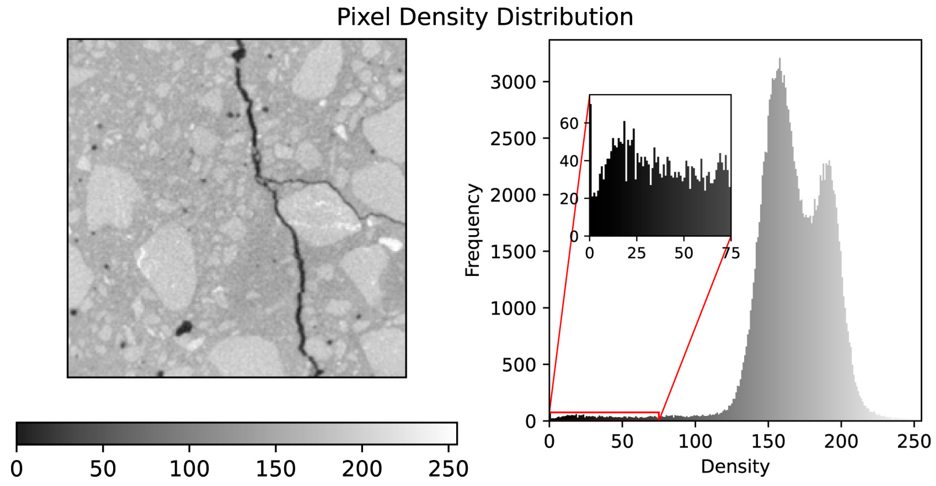
Figure 12: Pixel density distribution of a CT-scan of fractured concrete. Adapted with permission from Reference [158]. Copyright © 2023, Elsevier.
- (2)Data-driven parameter calibration and uncertainty quantification: DNNs can serve as “surrogate models” to replace computationally expensive physics-based simulations for massive parameter sweeps. Using methods such as BNNs, they can not only predict optimal parameter sets but also quantify the uncertainty of predictions, providing risk-informed decision intervals for engineering applications. For example, in an EGS project, historical injection pressure and production temperature data can be used to train a DNN to invert the reservoir’s permeability and stress fields; the resulting model can then directly inform the optimization of injection strategies for subsequent operational phases [159].
- (3)Intelligent generation and augmentation: When field data are extremely scarce, GANs or VAEs can generate large ensembles of geologically plausible “synthetic fracture networks” based on limited statistical priors. These synthetic datasets can be used to augment training data or enable Monte Carlo–based risk analysis, effectively alleviating data scarcity bottlenecks.
- (4)Cross-scale correlation modeling: ML excels at integrating multi-source, multi-scale data. For example, by using both macro-scale geophysical attributes (e.g., seismic velocity, resistivity) and micro-scale digital rock image features as joint inputs, a DNN can be trained to predict a reservoir-scale Fracture Intensity Index (FSI), enabling an intelligent leap from “point” (borehole) to “area” (reservoir) characterization.
In summary, the accurate characterization of complex fracture networks has evolved from a purely geometric modeling problem into a systems-level endeavor that integrates data, models, and intelligence. ML is not intended to replace physics-based models; rather, it equips them with an “intelligent eye” and “accelerating wings”, enabling automatic extraction of critical information from massive datasets and efficient constraint of model parameters—ultimately allowing us to “see through” and “preview” the subsurface world. Looking ahead, with the advancement of cutting-edge technologies such as Physics-Informed Machine Learning (PIML) and GNNs, we are poised to develop a new generation of intelligent characterization models that faithfully capture geological complexity while maintaining physical consistency and computational efficiency—paving a transformative path toward safer and more effective deep Earth engineering.
7.4 Theoretical Model Innovation
The theoretical foundation of current multiphysics coupling research in fractured rock masses is primarily built upon the framework of classical Continuum Mechanics (CM). However, this theoretical system faces fundamental limitations when applied to naturally discontinuous, multi-fractured media like rock [160]. The continuum assumption requires the material to be defect-free and infinitely differentiable at all scales—a premise fundamentally incompatible with the pervasive presence of discontinuities (joints, faults, bedding planes) in fractured rock and the processes of fracture initiation, propagation, and coalescence under stress. To overcome this theoretical bottleneck, developing new modeling frameworks that inherently accommodate discontinuities has become the most cutting-edge and potentially transformative research direction in the field. Among these, Peridynamics (PD) and Continuum-Discontinuum Coupling Methods represent two of the most promising pathways.
7.4.1 Beyond CM: Inherent Limitations of Classical Theory
Traditional numerical methods—such as the FEM—must either predefine crack paths or rely on complex fracture criteria (e.g., maximum tensile stress criterion, energy release rate criterion) when simulating rock fracturing. This approach is inherently descriptive rather than predictive. When crack paths are unknown or involve complex branching and coalescence, such models often fail. Moreover, FEM suffers from numerical instability in strongly discontinuous problems involving large deformations or fragmentation, due to severe mesh distortion. This necessitates frequent and costly remeshing, which not only increases computational expense but also introduces ambiguity in the physical interpretation of results. These shortcomings stem from the mathematical foundation of FEM—PDEs—which require field variables (e.g., displacement, stress) to be spatially continuous and differentiable, whereas real rock fracture is an inherently discontinuous and nonlocal physical process.
7.4.2 PD: A Revolutionary Breakthrough in Nonlocal Theory
PD is a novel solid mechanics theory based on nonlocal integral equations. Its core idea is to abandon the concept of spatial derivatives and instead describe a material’s mechanical behavior through long-range interaction forces between material points and their neighbors. In the PD framework, a body is discretized into a set of finite-volume “material points”, each connected to other points within a finite distance—known as the “horizon”—via pairwise “bonds”. Material damage is represented by bond breakage: when the relative displacement between two connected points exceeds a critical threshold, the bond breaks. This mechanism naturally captures crack initiation, propagation, and branching without requiring predefined crack paths or additional fracture criteria.
The core advantages of PD lie in:
- Native handling of discontinuities: Crack initiation and propagation emerge naturally from the model solution rather than through artificial intervention. This gives PD unparalleled advantages in simulating complex fracture networks and fragmentation processes.
- Mesh-free and derivative-free formulation: Since PD does not rely on spatial derivatives, it is immune to mesh distortion, making it especially well-suited for simulating large deformations and extreme failure scenarios.
- Nonlocality: The “horizon” in PD inherently incorporates nonlocal material interactions, enabling a more physically realistic representation of phenomena such as stress wave propagation and dynamic fracture.
- To date, PD theory has evolved from the original bond-based formulation to the more general state-based framework and has been successfully extended to multiphysics coupling domains such as TM and hydro-mechanical processes. It has demonstrated significant potential in simulating engineering problems like hydraulic fracturing, rockbursts, and slope instability, and is increasingly regarded as a “game-changer” for the future of theoretical modeling in rock mechanics [161].
Despite its conceptual elegance, the practical deployment of PD in realistic subsurface environments demands explicit integration with THMC coupling physics. In geothermal reservoir stimulation, for instance, thermal contraction induces tensile stresses that concentrate at pre-existing fracture tips—a classical stress singularity under continuum theory. Similarly, during CO2-brine-rock interactions, localized mineral dissolution creates sharp porosity/permeability fronts, while pore pressure diffusion across fracture-matrix interfaces generates discontinuous hydraulic gradients. These multiscale, multiphysics discontinuities challenge the differentiability assumptions of PDE-based models.
PD’s nonlocal integral formulation inherently circumvents this limitation: by replacing spatial derivatives with finite integrals over a horizon, field variables need not be continuous or differentiable. This provides a mathematically consistent framework to resolve stress concentrations at crack tips and abrupt changes in temperature, concentration, or pore pressure without enrichment or regularization.
However, extending PD to fully coupled THMC systems introduces significant numerical challenges. First, formulating nonlocal constitutive laws that consistently couple thermal expansion, fluid pressure, chemical potential, and bond failure remains an open problem. Second, the explicit time integration typically used in PD becomes prohibitively restrictive when stiff diffusive (e.g., heat conduction) or reactive (e.g., dissolution kinetics) processes are included, often requiring time steps orders of magnitude smaller than those in mechanical-only simulations. Third, the dense interaction matrix in 3D nonlocal models leads to O(N2) memory and computational complexity, which is exacerbated when multiple fields (T, H, M, C) each require their own horizon-based operators. Addressing these issues—through implicit PD schemes, adaptive horizons, or hybrid local–nonlocal coupling—is essential for PD to transition from a fracture mechanics tool to a predictive THMC simulator.
7.4.3 Continuum-Discontinuum Coupling Methods: Integrating Macroscopic Efficiency with Microscopic Fidelity
Whereas PD seeks to reconstruct the theoretical foundation from the ground up, continuum-discontinuum coupling methods represent a pragmatic engineering strategy that aims to combine the computational efficiency of continuum models with the fracture-representation fidelity of discrete approaches. The core idea is to apply different modeling scales within the same computational domain: use an efficient FEM in regions far from fractures (“continuum zones”), and switch to discrete models—such as the DEM or extended Finite Element Method (XFEM)—in areas where fracturing is anticipated or has already occurred (“discontinuum zones”). Seamless transfer of data and energy across the coupling interface is achieved through carefully designed algorithms, ensuring physical consistency and numerical stability.
Typical coupling frameworks include:
- FEM-DEM coupling: FEM is used at the macroscale to simulate the overall deformation of the rock mass, while DEM particles are embedded in localized high-stress zones or along predefined weak planes to model fracture opening, sliding, and fragmentation. This approach captures both the global stress field and the detailed local fracture processes, and has been successfully applied in tunnel excavation and hydraulic fracturing simulations.
- FEM-XFEM coupling: The XFEM introduces enrichment functions into the FEM framework, enabling cracks to propagate arbitrarily within elements without requiring remeshing. The FEM-XFEM coupled model can efficiently simulate the evolution of complex crack networks while preserving the original FEM mesh structure.
The advantages of hybrid methods lie in:
- High computational efficiency: High-cost discrete models are employed only in critical regions, significantly reducing the overall computational burden.
- Clear physical mechanisms: Classical CM retains its interpretability in continuous regions, while fracture behavior is accurately captured in discontinuous zones.
- Strong engineering applicability: These methods can be readily integrated into existing commercial software frameworks, facilitating adoption and practical implementation by engineers.
- In summary, the ultimate goal of theoretical model innovation is to establish a universal framework capable of consistently describing the entire spectrum of rock behavior—from continuous deformation to discontinuous fracture. Peridynamics, with its revolutionary nonlocal formulation, offers a fundamentally new mathematical foundation toward this vision. Meanwhile, continuum-discontinuum coupling methods provide practical, engineering-oriented solutions for today’s complex geomechanical challenges. Looking ahead, as computational power grows and theoretical frameworks mature, we may witness the dawn of a “post-continuum mechanics” era—one in which rock “fracturing” is no longer a modeling deficiency, but rather the central and most authentic physical attribute of the material itself [162].
7.5 Efficient Numerical Algorithms
As the physical fidelity and geometric complexity of multiphysics coupling models for fractured rock masses continue to increase, the computational challenges in their numerical solution have grown exponentially. Modern high-fidelity models—such as fully coupled THMC-DFN simulations or peridynamics—often involve millions to hundreds of millions of degrees of freedom, with governing equations characterized by strong nonlinearity, tight multiphysics coupling, and multiscale features. Traditional serial solvers and general-purpose commercial software are no longer adequate for such large-scale, highly nonlinear problems. Consequently, the development of efficient, robust, and scalable next-generation numerical algorithms has become the critical enabler for translating theoretical advances into practical engineering applications. Achieving this goal hinges on two pillars: leveraging advanced parallel computing architectures and strategically integrating AI/ML.
7.5.1 Parallel Computing and Solver Development for Large-Scale, Strongly Nonlinear Problems
Modern high-performance computing (HPC) provides the hardware foundation to address computational bottlenecks, but fully harnessing its potential requires the development of advanced algorithms specifically designed to exploit its capabilities:
- (1)Large-Scale Parallelization and Domain Decomposition Techniques:
For computationally intensive models such as DFN or FEM-DEM, large-scale parallel computing strategies are essential. By employing domain decomposition methods, the entire computational domain is partitioned into multiple subdomains, each assigned to a different computing node for concurrent solution, significantly reducing simulation time [163]. For instance, when simulating a kilometer-scale EGS reservoir, the domain can be divided into hundreds of subregions, enabling near-linear speedup on supercomputing clusters.
- (2)Efficient Solvers for Nonlinear Systems:
THMC-coupled equations fundamentally form a strongly nonlinear system of algebraic equations. The traditional Newton-Raphson method often struggles with convergence in highly nonlinear or ill-conditioned systems due to sensitivity to initial guesses or singularity of the Jacobian matrix. To address this, more robust solver strategies are required:
- Preconditioning techniques: Design efficient preconditioners—such as multigrid methods or incomplete LU (ILU) factorization—to improve the condition number of the Jacobian matrix and accelerate iterative convergence.
- Globally convergent algorithms: Incorporate trust-region methods or homotopy continuation strategies to enhance global convergence, especially when the initial guess is far from the true solution.
- Matrix-free methods: For extremely large-scale problems, avoid explicitly assembling and storing the full Jacobian matrix; instead, approximate its action via automatic differentiation or finite differences, drastically reducing memory consumption.
- (3)Efficient Algorithms for Multiphysics Coupling:
Fully implicit solution of strongly coupled problems (e.g., TMH) leads to a dramatic increase in the size and complexity of the global system matrix. To mitigate this, partitioned solvers or loosely coupled algorithms are essential. For example, a staggered iterative strategy—such as “implicit solution of the mechanical field + explicit update of the hydraulic field” [164]—can significantly reduce the computational cost per time step while maintaining numerical stability.
- (4)Adaptive Meshing and Dynamic Load Balancing:
When simulating localized processes such as fracture propagation or shear slip, Adaptive Mesh Refinement (AMR) dynamically refines the mesh in critical regions—such as fracture tips—while maintaining a coarser discretization in the far field. This strategy optimizes computational resources by preserving accuracy where it matters most without unnecessary overhead elsewhere. Coupled with dynamic load balancing algorithms, AMR ensures uniform computational workload across all processing nodes, preventing performance bottlenecks caused by localized mesh refinement.
7.5.2 Strategic Integration of AI/ML for Acceleration and Optimization
AI/ML is not merely an independent predictive tool; its deeper value lies in its role as a “computational accelerator” and “intelligent optimizer”, deeply embedded within traditional numerical solution workflows to achieve revolutionary gains in computational efficiency:
- (1)AI Surrogate Modeling:
Train DNNs or GPR models as high-speed surrogates for computationally expensive physics-based simulations. For instance, a DNN can replace time-consuming LBM or DFN simulations, reducing a single simulation from hours to seconds—enabling rapid parameter sensitivity analysis, uncertainty quantification, or real-time optimization control [165]. In EGS design, engineers can use such surrogate models to evaluate thousands of design scenarios within minutes, a task that would take months with conventional methods.
- (2)AI-Driven Solver Acceleration:
- Intelligent preconditioners: Use GNNs to learn the structural features of the system matrix and automatically generate optimal preconditioners, significantly accelerating the convergence of linear solvers [166].
- Convergence path prediction: Train ML models to forecast the convergence behavior of nonlinear iterations, enabling dynamic adjustment of step sizes or switching between solution strategies to avoid unproductive iterations.
- Adaptive time-step control: Employ RL-based intelligent controllers that dynamically adjust the time step based on real-time system states, maximizing computational efficiency while maintaining solution accuracy.
- (3)AI-Optimized Model Parameters and Design Variables:
Integrate AI/ML with optimization algorithms—such as genetic algorithms or Bayesian optimization—to establish an “intelligent optimization loop”. For example, in tunnel support design, a surrogate model can be trained with support parameters (e.g., bolt spacing, shotcrete thickness) as inputs and key performance indicators (e.g., rock mass displacement, seepage rate) as outputs. Bayesian optimization then automatically explores the design space to identify the optimal support configuration, drastically reducing the design cycle from weeks or months to hours or days.
- (4)Multifidelity Modeling and Transfer Learning:
Construct a hybrid architecture combining a low-fidelity physics-based model (e.g., ECM) with a high-fidelity AI corrector. The AI component learns the error mapping between the low-fidelity and high-fidelity models (e.g., DFN), enabling near-high-fidelity predictions at a fraction of the computational cost. Transfer learning further enhances efficiency by allowing a model trained in one context—such as a laboratory-scale experiment—to be rapidly adapted to a different context, such as a field-scale engineering application, significantly reducing the need for redundant training and data collection.
In summary, the future of efficient numerical algorithms lies in the deep integration of computational science, applied mathematics, and AI. Neither hardware upgrades alone nor incremental algorithmic improvements are sufficient to meet the ever-growing computational demands. Only by treating AI/ML as a “meta-algorithm”—strategically embedding it into the core components of numerical simulation, from mesh generation and equation solving to parameter optimization—can we build a truly next-generation “intelligent computational engine”. This engine will not only overcome current bottlenecks in large-scale, strongly nonlinear problems but also unlock transformative possibilities for multiphysics coupling research in fractured rock masses, propelling the field from being merely “computable” toward a new era of “real-time optimization” and “autonomous decision-making”.
In summary, research on multiphysics coupling in fractured rock masses is undergoing a pivotal paradigm shift—spanning from the fundamental challenge of characterizing complex fracture networks, through groundbreaking theoretical innovations, to the engineering implementation of highly efficient numerical algorithms. Table 9 systematically outlines these core challenges and future directions, providing a clear roadmap for the technological evolution of the field.
Table 9: Core challenges and future directions in multiphysics coupling research for fractured rock masses.
| Core Challenges | Key Scientific Questions | Future Research Directions and Technical Pathways |
|---|---|---|
| Multiscale Coupled Modeling | How can microscale mechanisms—such as non-Darcy flow and water–rock reactions—be effectively bridged to macroscale rock mass behavior? | Develop advanced homogenization techniques, nested coupling strategies, and data-driven cross-scale correlation models to enable faithful transfer of physical mechanisms across scales. |
| Model and Parameter Uncertainty | How can reliable THMC coupling parameters be obtained under extreme high-temperature and high-pressure conditions? | Develop high-fidelity in situ experimental platforms and extreme-environment-resistant intelligent sensors—such as distributed fiber-optic systems and nanoscale probes—and integrate them with data assimilation techniques to dynamically update and calibrate model parameters. |
| Characterization of Complex Fracture Networks | How can three-dimensional, stochastic, and intersecting fracture networks be realistically and efficiently characterized, along with their controlling influence on fluid flow? | Integrate ML (e.g., DNNs, GNNs) for inverse modeling and parameter constraint, and develop intelligent generative algorithms (e.g., GANs) to alleviate data scarcity. |
| Experimental Technology Innovation | How can we overcome the limitations of current laboratory equipment in simulating realistic reservoir conditions—specifically high temperature, high pressure, and multiphysics coupling? | Promote interdisciplinary collaboration to develop next-generation true-triaxial THMC coupled testing systems and downhole in situ monitoring technologies, providing high-fidelity validation benchmarks for numerical models. |
| Theoretical Model Innovation | How can we move beyond classical continuum mechanics to natively handle the discontinuities and fracture processes inherent in rock? | Develop PD and continuum-discontinuum coupling methods (e.g., FEM-DEM, FEM-XFEM) to establish a unified theoretical framework capable of consistently describing the entire process from deformation to fracture. |
| Efficient Numerical Algorithms | How can we address the computational bottlenecks posed by large-scale, strongly nonlinear, multiphysics coupled problems? | Develop large-scale parallel solvers and adaptive algorithms, and strategically integrate AI/ML techniques—such as PINNs and surrogate models—to enable computational acceleration and intelligent optimization. |
8.1 Summary of Key Research Findings
This review synthesizes recent advances in understanding fluid flow and THMC coupling in fractured rock masses, highlighting a unifying principle: hydraulic behavior is inherently nonlinear, stress-sensitive, path-dependent, and dynamically evolving—defying simplistic or static representations.
A central finding is the bidirectional “closure-dilation” mechanism governed by effective stress. Permeability decays exponentially as normal stress closes fractures, yet can surge during shear-induced dilation. Critically, this process exhibits strong hysteresis: permeability trajectories differ during loading versus unloading, meaning the current hydraulic state encodes the full stress history. Consequently, models ignoring path dependence inevitably misrepresent real rock behavior.
This mechanism underpins major engineering phenomena: in EGS, cold-water injection induces thermal stresses that trigger shear slip and fracture activation; in tunneling, excavation unloading can cause shear dilation and water/mud inrush; in nuclear waste disposal, thermal pulses alter fracture connectivity and radionuclide transport pathways. Thus, predicting and controlling dilation is pivotal to safety and performance.
Modeling approaches must be selected based on scale, objective, and data availability:
- ECM offer computational efficiency for large-scale far-field analysis but require a REV;
- DFN models provide high-fidelity near-field simulation of DFNs, ideal for critical zones like EGS wellbores or tunnel walls, albeit at high computational cost;
- Dual-porosity/permeability models balance efficiency and physics for reservoir-scale simulations with multiscale fractures.
Complementary numerical methods (FEM, DEM, LBM, BEM) should be chosen according to dominant physical processes (e.g., large deformation, non-Darcy flow). Crucially, model validity depends on alignment between its assumptions and actual geological conditions—no matter how elegant, a geologically detached model lacks predictive power.
In essence, the field has evolved from empirical descriptions toward an integrated, multiscale, multiphysics framework. Future progress hinges on two challenges: (1) faithfully capturing the dynamic stress–deformation–seepage coupling chain, and (2) reliably upscaling microscale mechanisms to inform macroscale predictions.
8.2 Implications for Engineering Practice
The practical value of this synthesis lies in actionable, scenario-specific modeling strategies grounded in fundamental physics and comprehensive site characterization—the cornerstone for reducing uncertainty.
- Nuclear Waste Disposal: Adopt a far-field–near-field nested coupling framework. Use ECM or dual-porosity models at kilometer scales for regional flow and thermal plume prediction; deploy DFN or PINNs at meter scales around canisters to resolve bentonite hydration, THM coupling, and fracture evolution under thermal pulses.
- EGS: Implement a dynamic optimization approach. During stimulation, use DFN or FEM-DEM to simulate shear-induced dilation from cold injection; during production, shift to efficient dual-porosity or AI surrogate models for long-term forecasting, enhanced by real-time data assimilation (e.g., microseismic inversion via ML).
- Tunneling: Focus on seepage–stress coupling for hazard prevention. Apply HM-coupled FEM during excavation to manage pore pressure and grouting; use THMC models in operation to assess long-term chemical degradation, freeze-thaw damage, and support stability—with uncertainty quantified via probabilistic or ML-based methods.
Across all scenarios, integrated site characterization is indispensable:
- (1)Fuse multiscale data (microscopic to regional) to build “point-to-volume” geological models;
- (2)Conduct multiphysics co-observation (e.g., DTS/DAS for concurrent temperature/strain);
- (3)Employ Bayesian inversion, EnKF, or ML surrogates for real-time parameter calibration;
- (4)Establish a closed-loop “characterization–modeling–validation” cycle that evolves throughout the project lifecycle.
Only through tight integration of advanced modeling and thorough characterization can we move from managing uncertainty toward deterministic prediction—ensuring the safety and sustainability of deep Earth engineering.
We summarize core findings and forward-looking priorities in Table 10. This structured overview underscores the interdependence among fundamental mechanisms, modeling strategies, engineering implementation, and emerging interdisciplinary frontiers—providing a roadmap for next-generation research.
Table 10: Summary of key research findings by theme and corresponding future directions.
| Theme/Aspect | Key Findings | Future Research Directions |
|---|---|---|
| Fundamental Flow Behavior | Fluid flow in fractured rock is highly nonlinear, stress-sensitive, path-dependent, and dynamically evolving; permeability is not constant but governed by effective stress and shear-induced dilation. | Develop constitutive models that explicitly embed hysteresis, memory effects, and irreversible deformation into permeability evolution laws. |
| Dilation Mechanism | Shear-induced fracture dilation is a critical physical bridge linking theory to engineering (e.g., EGS stimulation, tunneling hazards, nuclear waste migration). | Quantify dilation thresholds under coupled THMC conditions and integrate them into real-time risk control systems. |
| Modeling Paradigms | ECM, DFN, and dual-porosity models each suit specific scales and purposes; model choice must align with REV existence, data availability, and computational constraints. | Advance adaptive hybrid frameworks that dynamically switch or nest modeling approaches based on local physics. |
| Numerical Methods | FEM, DEM, LBM, BEM offer complementary strengths for different physical regimes (e.g., large deformation, non-Darcy flow). | Promote interoperable solvers and standardized interfaces for multi-method coupling (e.g., FEM-DEM-LBM). |
| Engineering Applications | Scenario-specific strategies are essential: nested modeling for nuclear waste, dynamic optimization for EGS, and lifecycle hazard modeling for tunnels. | Build digital twins that integrate real-time monitoring, AI updating, and physics-based simulation for operational decision support. |
| Site Characterization | Multiscale, multiphysics data integration is the foundation for reducing model uncertainty. | Establish “characterization–modeling–validation” closed loops using Bayesian inversion, EnKF, and distributed sensing (e.g., DTS/DAS). |
| Interdisciplinary Integration | Breakthroughs require convergence of AI, computational science, materials science, and rock mechanics. | Foster co-designed research programs that jointly develop sensors, models, and validation protocols across disciplines. |
| Global Collaboration | Benchmarking (e.g., DECOVALEX) and open data are vital for model credibility and reproducibility. | Create international open repositories for fractured rock data, models, and V&V standards for key engineering scenarios. |
To translate the promise of AI into reliable engineering practice, we propose a three-phase research roadmap aligned with data availability, model fidelity, and deployment readiness:
Short-term (1–3 years): Focus on hybridizing validated ML models (e.g., RF, shallow ANNs) with domain knowledge—such as incorporating rock mass rating rules or Darcy’s law as feature constraints. Prioritize standardization of small-scale labeled datasets from borehole logs, core imaging, and microseismic monitoring, and deploy these models in low-risk decision support tasks (e.g., preliminary rock classification or injection zone screening).
Medium-term (3–7 years): Develop physics-informed deep learning frameworks that embed conservation laws (mass, momentum, energy) as hard or soft constraints. Integrate multi-source data (geophysical, geochemical, mechanical) via multimodal architectures, and validate surrogate models against controlled field experiments (e.g., in-situ stimulation tests at underground research laboratories). Active learning strategies should guide targeted data acquisition under critical THMC conditions.
Long-term (7–15+ years): Realize autonomous, self-calibrating digital twins of deep subsurface systems capable of real-time forecasting and risk-aware control. This requires breakthroughs in few-shot domain adaptation across geological settings, explainable AI for regulatory trust, and robust uncertainty quantification under extreme data sparsity. Close collaboration among geoscientists, AI researchers, and regulators will be essential to establish certification protocols for safety-critical applications such as nuclear waste repositories or deep geothermal reservoirs.
The field is entering a transition phase where breakthroughs will stem not from isolated advances, but from deep interdisciplinary integration:
- AI & computational science will shift from auxiliary tools to core simulation engines, with PINNs, GNNs, and operator learning enabling real-time, physics-consistent solutions;
- Materials science will enable extreme-environment sensing (e.g., quantum dots) and refine chemo-mechanical constitutive laws;
- Rock mechanics will transcend continuum limits via peridynamics and hybrid continuum–discontinuum frameworks.
Three technical directions will dominate the next decade:
- (1)Physics-informed AI to embed conservation laws into neural networks, ensuring extrapolatable predictions;
- (2)Hybrid modeling, combining interpretable physics-based baselines with AI correctors for high-accuracy, high-trust forecasts;
- (3)Intelligent multiscale simulation, dynamically linking pore-, fracture-, and reservoir-scale domains via adaptive homogenization and ML-based cross-scale mapping.
Accelerating progress demands global collaboration: strengthening initiatives like DECOVALEX, building open data/model repositories, and establishing unified Verification & Validation (V&V) standards for key applications. Only through shared benchmarks and transparent validation can models gain the reliability needed for engineering decision-making.
We stand at an inflection point—where intelligent, physics-grounded digital twins of fractured rock systems are within reach. Achieving this vision is both a scientific imperative and an engineering necessity for the sustainable development of subsurface resources.
Acknowledgement:
Funding Statement: The authors received no specific funding.
Author Contributions: Zhuo Pan: methodology, writing—original draft. Lin Zhu: writing—review & editing. Yi Xue: data curation, conceptualization. Hao Xu: writing—review & editing. All authors reviewed and approved the final version of the manuscript.
Availability of Data and Materials: The datasets generated and/or analyzed during the current study are available from the corresponding author on reasonable request.
Ethics Approval: Not applicable.
Conflicts of Interest: The authors declare no conflicts of interest.
References
1. Zhang B , Wang L , Liu J . Finite element analysis and prediction of rock mass permeability based on a two-dimensional plane discrete fracture model. Processes. 2023; 11( 7): 1962. doi:10.3390/pr11071962. [Google Scholar] [CrossRef]
2. Frenelus W , Peng H , Zhang J . Seepage actions and their consequences on the support scheme of deep-buried tunnels constructed in soft rock strata. Infrastructures. 2024; 9( 1): 13. doi:10.3390/infrastructures9010013. [Google Scholar] [CrossRef]
3. Rathnaweera TD , Wu W , Ji Y , Gamage RP . Understanding injection-induced seismicity in enhanced geothermal systems: From the coupled thermo-hydro-mechanical-chemical process to anthropogenic earthquake prediction. Earth Sci Rev. 2020; 205: 103182. doi:10.1016/j.earscirev.2020.103182. [Google Scholar] [CrossRef]
4. Liu X , Li M , Zeng N , Li T . Investigation on nonlinear flow behavior through rock rough fractures based on experiments and proposed 3-dimensional numerical simulation. Geofluids. 2020; 2020( 1): 8818749. doi:10.1155/2020/8818749. [Google Scholar] [CrossRef]
5. Zhao X , Yang B , Niu Y , Yang C . Seepage-fractal characteristics of fractured media rock materials due to high-velocity non-darcy flow. Fractal Fract. 2022; 6( 11): 685. doi:10.3390/fractalfract6110685. [Google Scholar] [CrossRef]
6. Zhao M , Kong D , Teng S , Shi J . Combined effects of the roughness, aperture, and fractal features on the equivalent permeability and nonlinear flow behavior of rock fracture networks. Phys Fluids. 2024; 36( 7): 074110. doi:10.1063/5.0208425. [Google Scholar] [CrossRef]
7. Costanza-Robinson MS , Estabrook BD , Fouhey DF . Representative elementary volume estimation for porosity, moisture saturation, and air-water interfacial areas in unsaturated porous media: Data quality implications. Water Resour Res. 2011; 47( 7): 2010WR009655. doi:10.1029/2010WR009655. [Google Scholar] [CrossRef]
8. Ghabezloo S , Sulem J , Guédon S , Martineau F . Effective stress law for the permeability of a limestone. Int J Rock Mech Min Sci. 2009; 46( 2): 297– 306. doi:10.1016/j.ijrmms.2008.05.006. [Google Scholar] [CrossRef]
9. Wang M , Li X , Yang S , Teng L , Chen Q , Jiang S . Research on deformation and fracture characteristics of the fractured rock mass under coupling of heavy rainfall infiltration and mining unloading. Front Earth Sci. 2022; 9: 792038. doi:10.3389/feart.2021.792038. [Google Scholar] [CrossRef]
10. Tsang CF . Coupled hydromechanical-thermochemical processes in rock fractures. Rev Geophys. 1991; 29( 4): 537– 51. doi:10.1029/91RG01832. [Google Scholar] [CrossRef]
11. Viswanathan HS , Ajo-Franklin J , Birkholzer JT , Carey JW , Guglielmi Y , Hyman JD , et al. From fluid flow to coupled processes in fractured rock: Recent advances and new frontiers. Rev Geophys. 2022; 60( 1): e2021RG000744. doi:10.1029/2021RG000744. [Google Scholar] [CrossRef]
12. Rutqvist J , Zheng L , Chen F , Liu HH , Birkholzer J . Modeling of coupled thermo-hydro-mechanical processes with links to geochemistry associated with bentonite-backfilled repository tunnels in clay formations. Rock Mech Rock Eng. 2014; 47( 1): 167– 86. doi:10.1007/s00603-013-0375-x. [Google Scholar] [CrossRef]
13. Seetharam SC , Thomas HR , Cleall PJ . Coupled thermo/hydro/chemical/mechanical model for unsaturated soils—Numerical algorithm. Int J Numer Meth Eng. 2007; 70( 12): 1480– 511. doi:10.1002/nme.1934. [Google Scholar] [CrossRef]
14. Witherspoon PA , Gale JE . Mechanical and hydraulic properties of rocks related to induced seismicity. Eng Geol. 1977; 11( 1): 23– 55. doi:10.1016/0013-7952(77)90018-7. [Google Scholar] [CrossRef]
15. Ishibashi T , Asanuma H , Mukuhira Y , Watanabe N . Laboratory hydraulic shearing of granitic fractures with surface roughness under stress states of EGS: Permeability changes and energy balance. Int J Rock Mech Min Sci. 2023; 170: 105512. doi:10.1016/j.ijrmms.2023.105512. [Google Scholar] [CrossRef]
16. Yao C , Shao Y , Yang J , Huang F , He C , Jiang Q , et al. Effects of fracture density, roughness, and percolation of fracture network on heat-flow coupling in hot rock masses with embedded three-dimensional fracture network. Geothermics. 2020; 87: 101846. doi:10.1016/j.geothermics.2020.101846. [Google Scholar] [CrossRef]
17. Vo U , Fall M , Sedano JÁI , Nguyen TS . A multiphysics model for the near-field evolution of a geological repository of radioactive waste. Minerals. 2023; 13( 12): 1535. doi:10.3390/min13121535. [Google Scholar] [CrossRef]
18. Bächler D , Kohl T . Coupled thermal–hydraulic–chemical modelling of enhanced geothermal systems. Geophys J Int. 2005; 161( 2): 533– 48. doi:10.1111/j.1365-246X.2005.02497.x. [Google Scholar] [CrossRef]
19. Li H , Tian H , Ma K . Seepage characteristics and its control mechanism of rock mass in high-steep slopes. Processes. 2019; 7( 2): 71. doi:10.3390/pr7020071. [Google Scholar] [CrossRef]
20. Vaezi I , Yoshioka K , De Simone S , Gómez-Castro BM , Paluszny A , Jalali M , et al. A review of thermo-hydro-mechanical modeling of coupled processes in fractured rock: From continuum to discontinuum perspective. J Rock Mech Geotech Eng. 2025; 17( 11): 7460– 88. doi:10.1016/j.jrmge.2025.04.033. [Google Scholar] [CrossRef]
21. Ma Y , Chen X , Hosking LJ , Yu HS , Thomas HR . THMC constitutive model for membrane geomaterials based on Mixture Coupling Theory. Int J Eng Sci. 2022; 171: 103605. doi:10.1016/j.ijengsci.2021.103605. [Google Scholar] [CrossRef]
22. Brace WF . A note on permeability changes in geologic material due to stress. Pure Appl Geophys. 1978; 116( 4): 627– 33. doi:10.1007/BF00876529. [Google Scholar] [CrossRef]
23. Zhao X , Huang B , Chen B , Hou M . Experimental investigation of the effect of evenly distributed pore pressure on rock damage. Lithosphere. 2022; 2021( Special 4): 1759146. doi:10.2113/2022/1759146. [Google Scholar] [CrossRef]
24. Chen Y , Zhou C . Stress/strain-dependent properties of hydraulic conductivity for fractured rocks. In: Developments in Hydraulic Conductivity Research. Houston, TX, USA: InTech; 2011. doi:10.5772/16007. [Google Scholar] [CrossRef]
25. Dhar A , Spohn H . Fourier’s law based on microscopic dynamics. Comptes Rendus Phys. 2019; 20( 5): 393– 401. doi:10.1016/j.crhy.2019.08.004. [Google Scholar] [CrossRef]
26. Suzuki K , Oda M , Kuwahara T , Hirama K . Material property changes in granitic rock during long-term immersion in hot water. Eng Geol. 1995; 40( 1–2): 29– 39. doi:10.1016/0013-7952(95)00012-7. [Google Scholar] [CrossRef]
27. Sabo MS , Beckingham LE . Porosity-permeability evolution during simultaneous mineral dissolution and precipitation. Water Resour Res. 2021; 57( 6): e2020WR029072. doi:10.1029/2020WR029072. [Google Scholar] [CrossRef]
28. Bucher F , Müller-Vonmoos M . Bentonite as a containment barrier for the disposal of highly radioactive wastes. Appl Clay Sci. 1989; 4( 2): 157– 77. doi:10.1016/0169-1317(89)90006-9. [Google Scholar] [CrossRef]
29. Rutqvist J , Tsang CF . Multiphysics processes in partially saturated fractured rock: Experiments and models from Yucca Mountain. Rev Geophys. 2012; 50( 3): 2012RG000391. doi:10.1029/2012RG000391. [Google Scholar] [CrossRef]
30. Farajpour I , Atamturktur S . Partitioned analysis of coupled numerical models considering imprecise parameters and inexact models. J Comput Civ Eng. 2014; 28( 1): 145– 55. doi:10.1061/(asce)cp.1943-5487.0000253. [Google Scholar] [CrossRef]
31. Lei Z , Zhang Y , Cui Q , Shi Y . The injection-production performance of an enhanced geothermal system considering fracture network complexity and thermo-hydro-mechanical coupling in numerical simulations. Sci Rep. 2023; 13: 14558. doi:10.1038/s41598-023-41745-7. [Google Scholar] [CrossRef]
32. Zhang H , Wan Z , Zhao Y , Zhang Y , Chen Y , Wang J , et al. Shear induced seepage and heat transfer evolution in a single-fractured hot-dry-rock. Comput Model Eng Sci. 2021; 126( 2): 443– 55. doi:10.32604/cmes.2021.013179. [Google Scholar] [CrossRef]
33. Ye Z , Ghassemi A . Injection-induced shear slip and permeability enhancement in granite fractures. J Geophys Res Solid Earth. 2018; 123( 10): 9009– 32. doi:10.1029/2018JB016045. [Google Scholar] [CrossRef]
34. Gholizadeh Doonechaly N , Abdel Azim RR , Rahman SS . A study of permeability changes due to cold fluid circulation in fractured geothermal reservoirs. Ground Water. 2016; 54( 3): 325– 35. doi:10.1111/gwat.12365. [Google Scholar] [CrossRef]
35. Jansen G , Miller SA . On the role of thermal stresses during hydraulic stimulation of geothermal reservoirs. Geofluids. 2017; 2017( 1): 4653278. doi:10.1155/2017/4653278. [Google Scholar] [CrossRef]
36. Blöcher MG , Zimmermann G , Moeck I , Brandt W , Hassanzadegan A , Magri F . 3D numerical modeling of hydrothermal processes during the lifetime of a deep geothermal reservoir. Geofluids. 2010; 10( 3): 406– 21. doi:10.1111/j.1468-8123.2010.00284.x. [Google Scholar] [CrossRef]
37. Marelis A , Beekman F , van Wees JD . 3D mechanical analysis of geothermal reservoir operations in faulted sedimentary aquifers using MACRIS. Geotherm Energy. 2024; 12( 1): 5. doi:10.1186/s40517-024-00284-8. [Google Scholar] [CrossRef]
38. Gens A , Guimaräes LDN , Olivella S , Sánchez M . Modelling thermo-hydro-mechano-chemical interactions for nuclear waste disposal. J Rock Mech Geotech Eng. 2010; 2( 2): 97– 102. doi:10.3724/sp.j.1235.2010.00097. [Google Scholar] [CrossRef]
39. Sánchez M , Pomaro B , Gens A . Coupled THM analysis of a full-scale test for high-level nuclear waste and spent fuel disposal under actual repository conditions during 18 years of operation. Géotechnique. 2023; 73( 5): 418– 38. doi:10.1680/jgeot.21.00106. [Google Scholar] [CrossRef]
40. Wu G , Chen W , Rong C , Jia S , Dai Y . Elastoplastic damage evolution constitutive model of saturated rock with respect to volumetric strain in rock and its engineering application. Tunn Undergr Space Technol. 2020; 97: 103284. doi:10.1016/j.tust.2020.103284. [Google Scholar] [CrossRef]
41. Berkowitz B , Bear J , Braester C . Continuum models for contaminant transport in fractured porous formations. Water Resour Res. 1988; 24( 8): 1225– 36. doi:10.1029/WR024i008p01225. [Google Scholar] [CrossRef]
42. Ma J . Review of permeability evolution model for fractured porous media. J Rock Mech Geotech Eng. 2015; 7( 3): 351– 7. doi:10.1016/j.jrmge.2014.12.003. [Google Scholar] [CrossRef]
43. Mortazavi SMS , Rezaie Beydokhti O , Khoei AR . Modeling enhanced geothermal systems using a hybrid XFEM–ECM technique. Appl Therm Eng. 2023; 230: 120755. doi:10.1016/j.applthermaleng.2023.120755. [Google Scholar] [CrossRef]
44. Elmo D , Rogers S , Stead D , Eberhardt E . Discrete Fracture Network approach to characterise rock mass fragmentation and implications for geomechanical upscaling. Min Technol. 2014; 123( 3): 149– 61. doi:10.1179/1743286314Y.0000000064. [Google Scholar] [CrossRef]
45. Li X , Li D , Xu Y , Feng X . A DFN based 3D numerical approach for modeling coupled groundwater flow and solute transport in fractured rock mass. Int J Heat Mass Transf. 2020; 149: 119179. doi:10.1016/j.ijheatmasstransfer.2019.119179. [Google Scholar] [CrossRef]
46. Hoefner ML , Fogler HS . Pore evolution and channel formation during flow and reaction in porous media. AlChE J. 1988; 34( 1): 45– 54. doi:10.1002/aic.690340107. [Google Scholar] [CrossRef]
47. Zhang Q , Dong S , Liu Y , Huang J , Xiong F . Algorithmic approach to discrete fracture network flow modeling in consideration of realistic connections in large-scale fracture networks. J Rock Mech Geotech Eng. 2024; 16( 9): 3798– 811. doi:10.1016/j.jrmge.2024.02.011. [Google Scholar] [CrossRef]
48. Blessent D , Jørgensen PR , Therrien R . Comparing discrete fracture and continuum models to predict contaminant transport in fractured porous media. Ground Water. 2014; 52( 1): 84– 95. doi:10.1111/gwat.12032. [Google Scholar] [CrossRef]
49. Phillips T , Kampman N , Bisdom K , Forbes Inskip ND , den Hartog SAM , Cnudde V , et al. Controls on the intrinsic flow properties of mudrock fractures: A review of their importance in subsurface storage. Earth Sci Rev. 2020; 211: 103390. doi:10.1016/j.earscirev.2020.103390. [Google Scholar] [CrossRef]
50. Gerke HH , van Genuchten MT . A dual-porosity model for simulating the preferential movement of water and solutes in structured porous media. Water Resour Res. 1993; 29( 2): 305– 19. doi:10.1029/92WR02339. [Google Scholar] [CrossRef]
51. Augarde CE , Lee SJ , Loukidis D . Numerical modelling of large deformation problems in geotechnical engineering: A state-of-the-art review. Soils Found. 2021; 61( 6): 1718– 35. doi:10.1016/j.sandf.2021.08.007. [Google Scholar] [CrossRef]
52. Sun X , Luo H , Soga K . A coupled thermal–hydraulic–mechanical–chemical (THMC) model for methane hydrate bearing sediments using COMSOL Multiphysics. J Zhejiang Univ Sci A. 2018; 19( 8): 600– 23. doi:10.1631/jzus.a1700464. [Google Scholar] [CrossRef]
53. Tian F , Tang X , Xu T , Li L . An adaptive edge-based smoothed finite element method (ES-FEM) for phase-field modeling of fractures at large deformations. Comput Meth Appl Mech Eng. 2020; 372: 113376. doi:10.1016/j.cma.2020.113376. [Google Scholar] [CrossRef]
54. Linder C , Armero F . Finite elements with embedded strong discontinuities for the modeling of failure in solids. Int J Numer Meth Eng. 2007; 72( 12): 1391– 433. doi:10.1002/nme.2042. [Google Scholar] [CrossRef]
55. Luding S . Introduction to discrete element methods. Basic of contact force models and how to perform the micro-macro transition to continuum theory. Rev Eur De Génie Civ. 2008; 12( 7–8): 785– 826. doi:10.3166/ejece.12.785-826. [Google Scholar] [CrossRef]
56. Ji S , Karlovšek J . Calibration and uniqueness analysis of microparameters for DEM cohesive granular material. Int J Min Sci Technol. 2022; 32( 1): 121– 36. doi:10.1016/j.ijmst.2021.11.003. [Google Scholar] [CrossRef]
57. Xu J , Zhao P , Zhang Y , Wang J , Ge W . Discrete particle methods for engineering simulation: Reproducing mesoscale structures in multiphase systems. Resour Chem Mater. 2022; 1( 1): 69– 79. doi:10.1016/j.recm.2022.01.002. [Google Scholar] [CrossRef]
58. Sato K , Horne RN . Perturbation boundary element method for heterogeneous reservoirs: Part 1—Steady-state flow problems. SPE Form Eval. 1993; 8( 4): 306– 14. doi:10.2118/25299-pa. [Google Scholar] [CrossRef]
59. Gray LJ , Phan AV , Kaplan T . Boundary integral evaluation of surface derivatives. SIAM J Sci Comput. 2004; 26( 1): 294– 312. doi:10.1137/s1064827502406002. [Google Scholar] [CrossRef]
60. Liu YJ , Nishimura N . The fast multipole boundary element method for potential problems: A tutorial. Eng Anal Bound Elem. 2006; 30( 5): 371– 81. doi:10.1016/j.enganabound.2005.11.006. [Google Scholar] [CrossRef]
61. Han Y , Cundall PA . Lattice Boltzmann modeling of pore-scale fluid flow through idealized porous media. Int J Numer Meth Fluids. 2011; 67( 11): 1720– 34. doi:10.1002/fld.2443. [Google Scholar] [CrossRef]
62. Kang Q , Zhang D , Chen S . Unified lattice Boltzmann method for flow in multiscale porous media. Phys Rev E Stat Nonlin Soft Matter Phys. 2002; 66( 5 Pt 2): 056307. doi:10.1103/PhysRevE.66.056307. [Google Scholar] [CrossRef]
63. Osuji NI , Niemi A , Tsang CF , Jiang C , Lei Q . Impact of multiscale anisotropy on flow and transport in three-dimensional fracture networks. Hydrogeol J. 2025; 33( 6): 1501– 28. doi:10.1007/s10040-025-02940-0. [Google Scholar] [CrossRef]
64. Sari M . Determination of representative elementary volume (REV) for jointed rock masses exhibiting scale-dependent behavior: A numerical investigation. Int J Geo Eng. 2021; 12( 1): 34. doi:10.1186/s40703-021-00164-1. [Google Scholar] [CrossRef]
65. Parker BL , Cherry JA , Chapman SW . Discrete fracture network approach for studying contamination in fractured rock. AQUA Mundi. 2012; 3( 2): 101– 16. [Google Scholar]
66. Gerke HH , van Genuchten MT . Evaluation of a first-order water transfer term for variably saturated dual-porosity flow models. Water Resour Res. 1993; 29( 4): 1225– 38. doi:10.1029/92WR02467. [Google Scholar] [CrossRef]
67. Faoro I , Niemeijer A , Marone C , Elsworth D . Influence of shear and deviatoric stress on the evolution of permeability in fractured rock. J Geophys Res Solid Earth. 2009; 114( B1): 2007JB005372. doi:10.1029/2007JB005372. [Google Scholar] [CrossRef]
68. Lavrov A . Fracture permeability under normal stress: A fully computational approach. J Petrol Explor Prod Technol. 2017; 7( 1): 181– 94. doi:10.1007/s13202-016-0254-6. [Google Scholar] [CrossRef]
69. Wang M , Yang Y , Zhou Y , Shi H , Huang J . The influence mechanism of effective stress, adsorption effect and Klinkenberg effect on coal seam permeability. Front Energy Res. 2023; 10: 979117. doi:10.3389/fenrg.2022.979117. [Google Scholar] [CrossRef]
70. Yuan Y , Xu T , Moore J , Lei H , Feng B . Coupled thermo–hydro–mechanical modeling of hydro-shearing stimulation in an enhanced geothermal system in the raft river geothermal field, USA. Rock Mech Rock Eng. 2020; 53( 12): 5371– 88. doi:10.1007/s00603-020-02227-8. [Google Scholar] [CrossRef]
71. Brunold CR , Hunns JCB , Mackley MR , Thompson JW . Experimental observations on flow patterns and energy losses for oscillatory flow in ducts containing sharp edges. Chem Eng Sci. 1989; 44( 5): 1227– 44. doi:10.1016/0009-2509(89)87022-8. [Google Scholar] [CrossRef]
72. Xue Y , Liu Y , Dang F , Liu J , Ma Z , Zhu L , et al. Assessment of the nonlinear flow characteristic of water inrush based on the brinkman and forchheimer seepage model. Water. 2019; 11( 4): 855. doi:10.3390/w11040855. [Google Scholar] [CrossRef]
73. Zhang X , Sanderson DJ . Effects of stress on the two-dimensional permeability tensor of natural fracture networks. Geophys J Int. 1996; 125( 3): 912– 24. doi:10.1111/j.1365-246X.1996.tb06034.x. [Google Scholar] [CrossRef]
74. Trimmer D , Bonner B , Heard HC , Duba A . Effect of pressure and stress on water transport in intact and fractured gabbro and granite. J Geophys Res Solid Earth. 1980; 85( B12): 7059– 71. doi:10.1029/JB085iB12p07059. [Google Scholar] [CrossRef]
75. Lei Q , Wang X , Xiang J , Latham JP . Polyaxial stress-dependent permeability of a three-dimensional fractured rock layer. Hydrogeol J. 2017; 25( 8): 2251– 62. doi:10.1007/s10040-017-1624-y. [Google Scholar] [CrossRef]
76. Auradou H , Drazer G , Boschan A , Hulin JP , Koplik J . Flow channeling in a single fracture induced by shear displacement. Geothermics. 2006; 35( 5–6): 576– 88. doi:10.1016/j.geothermics.2006.11.004. [Google Scholar] [CrossRef]
77. Shackelford CD , Javed F . Large-scale laboratory permeability testing of a compacted clay soil. Geotech Test J. 1991; 14( 2): 171– 9. doi:10.1520/gtj10559j. [Google Scholar] [CrossRef]
78. Rutqvist J . Fractured rock stress-permeability relationships from in situ data and effects of temperature and chemical-mechanical couplings. Geofluids. 2015; 15( 1–2): 48– 66. doi:10.1111/gfl.12089. [Google Scholar] [CrossRef]
79. Xue K , Zhang Z , Hao S , Luo P , Wang Y . On the onset of nonlinear fluid flow transition in rock fracture network: Theoretical and computational fluid dynamic investigation. Phys Fluids. 2022; 34( 12): 125114. doi:10.1063/5.0130652. [Google Scholar] [CrossRef]
80. Zou L , Cvetkovic V . Disposal of high-level radioactive waste in crystalline rock: On coupled processes and site development. Rock Mech Bull. 2023; 2( 3): 100061. doi:10.1016/j.rockmb.2023.100061. [Google Scholar] [CrossRef]
81. Tsang CF . Linking thermal, hydrological, and mechanical processes in fractured rocks. Annu Rev Earth Planet Sci. 1999; 27: 359– 84. doi:10.1146/annurev.earth.27.1.359. [Google Scholar] [CrossRef]
82. Félix B , Lebon P , Miguez R , Plas F . A review of the ANDRA’s research programmes on the thermo-hydromechanical behavior of clay in connection with the radioactive waste disposal project in deep geological formations. Eng Geol. 1996; 41( 1–4): 35– 50. doi:10.1016/0013-7952(95)00025-9. [Google Scholar] [CrossRef]
83. Rutqvist J , Chijimatsu M , Jing L , Millard A , Nguyen TS , Rejeb A , et al. A numerical study of THM effects on the near-field safety of a hypothetical nuclear waste repository—BMT1 of the DECOVALEX III project. Part 3: Effects of THM coupling in sparsely fractured rocks. Int J Rock Mech Min Sci. 2005; 42( 5–6): 745– 55. doi:10.1016/j.ijrmms.2005.03.012. [Google Scholar] [CrossRef]
84. Zheng X , Underwood TR , Bourg IC . Molecular dynamics simulation of thermal, hydraulic, and mechanical properties of bentonite clay at 298 to 373 K. Appl Clay Sci. 2023; 240: 106964. doi:10.1016/j.clay.2023.106964. [Google Scholar] [CrossRef]
85. Wang YP , Wang Z , Zeng ZQ , Yi FC , Luo Y . A numerical simulation study on the migration of the 90Sr nuclide of buffer material under the coupling effect of multiple factors. Sustainability. 2024; 16( 23): 10537. doi:10.3390/su162310537. [Google Scholar] [CrossRef]
86. Neretnieks I . Diffusion in the rock matrix: An important factor in radionuclide retardation? J Geophys Res Solid Earth. 1980; 85( B8): 4379– 97. doi:10.1029/JB085iB08p04379. [Google Scholar] [CrossRef]
87. Sanchez-Roa C , Saldi GD , Mitchell TM , Iacoviello F , Bailey J , Shearing PR , et al. The role of fluid chemistry on permeability evolution in granite: Applications to natural and anthropogenic systems. Earth Planet Sci Lett. 2021; 553: 116641. doi:10.1016/j.epsl.2020.116641. [Google Scholar] [CrossRef]
88. Li SH , Chiou SL . Radionuclide migration in fractured porous rock: Analytical solution for a kinetic solubility-limited dissolution model. Nucl Technol. 1993; 104( 2): 258– 71. doi:10.13182/NT93-A34889. [Google Scholar] [CrossRef]
89. Hyman JD , Dentz M , Hagberg A , Kang PK . Linking structural and transport properties in three-dimensional fracture networks. J Geophys Res Solid Earth. 2019; 124( 2): 1185– 204. doi:10.1029/2018JB016553. [Google Scholar] [CrossRef]
90. Bros R , Carpena J , Sere V , Beltritti A . Occurrence of Pu and fissiogenic REE in hydrothermal apatites from the fossil nuclear reactor 16 at oklo (Gabon). Radiochim Acta. 1996; 74( s1): 277– 82. doi:10.1524/ract.1996.74.special-issue.277. [Google Scholar] [CrossRef]
91. Breede K , Dzebisashvili K , Liu X , Falcone G . A systematic review of enhanced (or engineered) geothermal systems: Past, present and future. Geotherm Energy. 2013; 1( 1): 4. doi:10.1186/2195-9706-1-4. [Google Scholar] [CrossRef]
92. Fredrich JT , Wong TF . Micromechanics of thermally induced cracking in three crustal rocks. J Geophys Res Solid Earth. 1986; 91( B12): 12743– 64. doi:10.1029/JB091iB12p12743. [Google Scholar] [CrossRef]
93. Rinaldi AP , Rutqvist J , Sonnenthal EL , Cladouhos TT . Coupled THM modeling of hydroshearing stimulation in tight fractured volcanic rock. Transp Porous Medium. 2015; 108( 1): 131– 50. doi:10.1007/s11242-014-0296-5. [Google Scholar] [CrossRef]
94. Zhou L , Zhu Z , Xie X , Hu Y . Coupled thermal–hydraulic–mechanical model for an enhanced geothermal system and numerical analysis of its heat mining performance. Renew Energy. 2022; 181: 1440– 58. doi:10.1016/j.renene.2021.10.014. [Google Scholar] [CrossRef]
95. Singh M , Mahmoodpour S , Bär K , Sass I . Heat extraction in geothermal systems with variable thermo-poroelastic fracture apertures. Geotechnics. 2023; 3( 4): 1196– 206. doi:10.3390/geotechnics3040065. [Google Scholar] [CrossRef]
96. Avanthi Isaka BL , Ranjith PG , Rathnaweera TD . The use of super-critical carbon dioxide as the working fluid in enhanced geothermal systems (EGSs): A review study. Sustain Energy Technol Assess. 2019; 36: 100547. doi:10.1016/j.seta.2019.100547. [Google Scholar] [CrossRef]
97. Liu H , Wang H , Lei H , Zhang L , Bai M , Zhou L . Numerical modeling of thermal breakthrough induced by geothermal production in fractured granite. J Rock Mech Geotech Eng. 2020; 12( 4): 900– 16. doi:10.1016/j.jrmge.2020.01.002. [Google Scholar] [CrossRef]
98. Sanyal SK , Butler SJ . An analysis of power generation prospects from enhanced geothermal systems. Geothermal Resources Council Transactions. 2005; 29: 131– 8. [Google Scholar]
99. Zhou W , Lanza F , Grigoratos I , Schultz R , Cousse J , Trutnevyte E , et al. Managing induced seismicity risks from enhanced geothermal systems: A good practice guideline. Rev Geophys. 2024; 62( 4): e2024RG000849. doi:10.1029/2024RG000849. [Google Scholar] [CrossRef]
100. Rutqvist J , Dobson PF , Garcia J , Hartline C , Jeanne P , Oldenburg CM , et al. The northwest geysers EGS demonstration project, California: Pre-stimulation modeling and interpretation of the stimulation. Math Geosci. 2015; 47( 1): 3– 29. doi:10.1007/s11004-013-9493-y. [Google Scholar] [CrossRef]
101. Yao Q , Ma Y , Xiao Z , Zhang Z , Lu Y , Liu C . Analysis of surrounding rock pressure of deep buried tunnel considering the influence of seepage. Geofluids. 2022; 2022( 1): 3644147. doi:10.1155/2022/3644147. [Google Scholar] [CrossRef]
102. Sun Q , De Corte W , Liu X , Taerwe L . Model test and numerical simulation for tunnel leakage-induced seepage erosion in different strata. Appl Sci. 2024; 14( 9): 3908. doi:10.3390/app14093908. [Google Scholar] [CrossRef]
103. Evans KF , Genter A , Sausse J . Permeability creation and damage due to massive fluid injections into granite at 3.5 km at Soultz: 1. Borehole observations. J Geophys Res Solid Earth. 2005; 110( B4): 2004JB003168. doi:10.1029/2004JB003168. [Google Scholar] [CrossRef]
104. Xie Q , Cao Z , Sun W , Fumagalli A , Fu X , Wu Z , et al. Numerical simulation of the fluid-solid coupling mechanism of water and mud inrush in a water-rich fault tunnel. Tunn Undergr Space Technol. 2023; 131: 104796. doi:10.1016/j.tust.2022.104796. [Google Scholar] [CrossRef]
105. Liu X , Xu G , Zhang C , Kong B , Qian J , Zhu D , et al. Time effect of water injection on the mechanical properties of coal and its application in rockburst prevention in mining. Energies. 2017; 10( 11): 1783. doi:10.3390/en10111783. [Google Scholar] [CrossRef]
106. Ma D , Duan H , Zhang J , Bai H . A state-of-the-art review on rock seepage mechanism of water inrush disaster in coal mines. Int J Coal Sci Technol. 2022; 9( 1): 50. doi:10.1007/s40789-022-00525-w. [Google Scholar] [CrossRef]
107. Wang J , Li S , Li L , Shi S , Zhou Z , Song S . Mechanism of water inrush in fractures and block collapse under hydraulic pressure. Math Comput Simul. 2020; 177: 625– 42. doi:10.1016/j.matcom.2020.05.028. [Google Scholar] [CrossRef]
108. Guo S , Pu H , Yang M , Liu D , Sha Z , Xu J . Study of the influence of clay minerals on the mechanical and percolation properties of weakly cemented rocks. Geofluids. 2022; 2022( 1): 1712740. doi:10.1155/2022/1712740. [Google Scholar] [CrossRef]
109. Zhong Z , Xu C , Wang L , Hu Y , Zhang F . Experimental investigation on frictional properties of stressed basalt fractures. J Rock Mech Geotech Eng. 2023; 15( 6): 1457– 75. doi:10.1016/j.jrmge.2022.12.020. [Google Scholar] [CrossRef]
110. Zhou MM , Meschke G . A three-phase thermo-hydro-mechanical finite element model for freezing soils. Num Anal Meth Geomechanics. 2013; 37( 18): 3173– 93. doi:10.1002/nag.2184. [Google Scholar] [CrossRef]
111. Taber S . Frost heaving. J Geol. 1929; 37( 5): 428– 61. doi:10.1086/623637. [Google Scholar] [CrossRef]
112. Sadiq MF , Naqvi MW , Cetin B , Daniels J . Role of temperature gradient and soil thermal properties on frost heave. Transp Res Rec J Transp Res Board. 2025; 2679( 1): 217– 26. doi:10.1177/03611981221147261. [Google Scholar] [CrossRef]
113. Zhao Y , Feng J , Liu K , Xu H , Wang L , Liu H . Study of the stability of a soil-rock road cutting slope in a permafrost region of Hulunbuir. Adv Civ Eng. 2020; 2020: 6701958. doi:10.1155/2020/6701958. [Google Scholar] [CrossRef]
114. Syed FI , AlShamsi A , Dahaghi AK , Neghabhan S . Application of ML & AI to model petrophysical and geomechanical properties of shale reservoirs—A systematic literature review. Petroleum. 2022; 8( 2): 158– 66. doi:10.1016/j.petlm.2020.12.001. [Google Scholar] [CrossRef]
115. Morgenroth J , Khan UT , Perras MA . An overview of opportunities for machine learning methods in underground rock engineering design. Geosciences. 2019; 9( 12): 504. doi:10.3390/geosciences9120504. [Google Scholar] [CrossRef]
116. Hui G , Ren Y , Bi J , Wang M , Liu C . Artificial intelligence applications and challenges in oil and gas exploration and development. Adv Geo-Energy Res. 2025; 17( 3): 179– 83. doi:10.46690/ager.2025.09.01. [Google Scholar] [CrossRef]
117. Lee HK , Song MK , Jeong YO , Lee SS . Development of an automatic rock mass classification system using digital tunnel face mapping. Appl Sci. 2024; 14( 19): 9024. doi:10.3390/app14199024. [Google Scholar] [CrossRef]
118. Matin SS , Farahzadi L , Makaremi S , Chelgani SC , Sattari G . Variable selection and prediction of uniaxial compressive strength and modulus of elasticity by random forest. Appl Soft Comput. 2018; 70: 980– 7. doi:10.1016/j.asoc.2017.06.030. [Google Scholar] [CrossRef]
119. Wu J , Yin X , Xiao H . Seeing permeability from images: Fast prediction with convolutional neural networks. Sci Bull. 2018; 63( 18): 1215– 22. doi:10.1016/j.scib.2018.08.006. [Google Scholar] [CrossRef]
120. Reinhardt M , Jacob A , Sadeghnejad S , Cappuccio F , Arnold P , Frank S , et al. Benchmarking conventional and machine learning segmentation techniques for digital rock physics analysis of fractured rocks. Environ Earth Sci. 2022; 81( 3): 71. doi:10.1007/s12665-021-10133-7. [Google Scholar] [CrossRef]
121. Erofeev AS , Orlov DM , Perets DS , Koroteev DA . AI-based estimation of hydraulic fracturing effect. SPE J. 2021; 26( 4): 1812– 23. doi:10.2118/205479-pa. [Google Scholar] [CrossRef]
122. Zhuang X , Liu Y , Hu Y , Guo H , Nguyen BH . Prediction of rock fracture pressure in hydraulic fracturing with interpretable machine learning and mechanical specific energy theory. Rock Mech Bull. 2025; 4( 2): 100173. doi:10.1016/j.rockmb.2024.100173. [Google Scholar] [CrossRef]
123. Mohammadinia F , Ranjbar A , Kafi M , Shams M , Haghighat F , Maleki M . Shale volume estimation using ANN, SVR, and RF algorithms compared with conventional methods. J Afr Earth Sci. 2023; 205: 104991. doi:10.1016/j.jafrearsci.2023.104991. [Google Scholar] [CrossRef]
124. Liu M , Ahmad R , Cai W , Mukerji T . Hierarchical homogenization with deep-learning-based surrogate model for rapid estimation of effective permeability from digital rocks. J Geophys Res Solid Earth. 2023; 128( 2): e2022JB025378. doi:10.1029/2022JB025378. [Google Scholar] [CrossRef]
125. Sun AY , Jiang P , Mudunuru MK , Chen X . Explore spatio-temporal learning of large sample hydrology using graph neural networks. Water Resour Res. 2021; 57( 12): e2021WR030394. doi:10.1029/2021WR030394. [Google Scholar] [CrossRef]
126. Raissi M , Perdikaris P , Karniadakis GE . Physics-informed neural networks: A deep learning framework for solving forward and inverse problems involving nonlinear partial differential equations. J Comput Phys. 2019; 378: 686– 707. doi:10.1016/j.jcp.2018.10.045. [Google Scholar] [CrossRef]
127. Yan X , Lin J , Wang S , Zhang Z , Liu P , Sun S , et al. Physics-informed neural network simulation of two-phase flow in heterogeneous and fractured porous media. Adv Water Resour. 2024; 189: 104731. doi:10.1016/j.advwatres.2024.104731. [Google Scholar] [CrossRef]
128. Nabian MA , Gladstone RJ , Meidani H . Efficient training of physics-informed neural networks via importance sampling. Comput Aided Civ Infrastruct Eng. 2021; 36( 8): 962– 77. doi:10.1111/mice.12685. [Google Scholar] [CrossRef]
129. Liu D , Wang Y . Multi-fidelity physics-constrained neural network and its application in materials modeling. J Mech Des. 2019; 141( 12): 121403. doi:10.1115/1.4044400. [Google Scholar] [CrossRef]
130. Saadati G , Javankhoshdel S , Mohebbi Najm Abad J , Mett M , Kontrus H , Schneider-Muntau B . AI-powered geotechnics: Enhancing rock mass classification for safer engineering practices. Rock Mech Rock Eng. 2025; 58( 10): 11319– 49. doi:10.1007/s00603-024-04189-7. [Google Scholar] [CrossRef]
131. Chen X , Zhang K , Ji Z , Shen X , Liu P , Zhang L , et al. Progress and challenges of integrated machine learning and traditional numerical algorithms: Taking reservoir numerical simulation as an example. Mathematics. 2023; 11( 21): 4418. doi:10.3390/math11214418. [Google Scholar] [CrossRef]
132. Khan S , Yairi T , Tsutsumi S , Nakasuka S . A review of physics-based learning for system health management. Annu Rev Control. 2024; 57: 100932. doi:10.1016/j.arcontrol.2024.100932. [Google Scholar] [CrossRef]
133. Thavarajah R , Zhai X , Ma Z , Castineira D . Fast modeling and understanding fluid dynamics systems with encoder–decoder networks. Mach Learn Sci Technol. 2021; 2( 2): 025022. doi:10.1088/2632-2153/abd1cf. [Google Scholar] [CrossRef]
134. Zhou CB , Chen YF , Hu R , Yang Z . Groundwater flow through fractured rocks and seepage control in geotechnical engineering: Theories and practices. J Rock Mech Geotech Eng. 2023; 15( 1): 1– 36. doi:10.1016/j.jrmge.2022.10.001. [Google Scholar] [CrossRef]
135. Ye J , Zeng W , Do NC , Lambert M . Reconstructing transient pressures in pipe networks from local observations by using physics-informed neural networks. Water Res. 2024; 257: 121648. doi:10.1016/j.watres.2024.121648. [Google Scholar] [CrossRef]
136. Neuman SP . Trends, prospects and challenges in quantifying flow and transport through fractured rocks. Hydrogeol J. 2005; 13( 1): 124– 47. doi:10.1007/s10040-004-0397-2. [Google Scholar] [CrossRef]
137. Fookes PG . Geology for engineers: The geological model, prediction and performance. Q J Eng Geol. 1997; 30( 4): 293– 424. doi:10.1144/gsl.qjeg.1997.030.p4.02. [Google Scholar] [CrossRef]
138. Ghoniem NM , Busso EP , Kioussis N , Huang H . Multiscale modelling of nanomechanics and micromechanics: An overview. Philos Mag. 2003; 83( 31–34): 3475– 528. doi:10.1080/14786430310001607388. [Google Scholar] [CrossRef]
139. Ekechukwu GK , Sharma J . Well-scale demonstration of distributed pressure sensing using fiber-optic DAS and DTS. Sci Rep. 2021; 11: 12505. doi:10.1038/s41598-021-91916-7. [Google Scholar] [CrossRef]
140. Zhu C , Xu X , Wang X , Xiong F , Tao Z , Lin Y , et al. Experimental investigation on nonlinear flow anisotropy behavior in fracture media. Geofluids. 2019; 2019( 1): 5874849. doi:10.1155/2019/5874849. [Google Scholar] [CrossRef]
141. Rostami P , Sharifi M , Dejam M . Shape factor for regular and irregular matrix blocks in fractured porous media. Petrol Sci. 2020; 17( 1): 136– 52. doi:10.1007/s12182-019-00399-9. [Google Scholar] [CrossRef]
142. Rodrigues Lopes IA , Andrade Pires FM . Formulation and numerical implementation of a variationally consistent multi-scale model based on second-order computational homogenisation at finite strains for quasi-static problems. Comput Meth Appl Mech Eng. 2022; 392: 114714. doi:10.1016/j.cma.2022.114714. [Google Scholar] [CrossRef]
143. Santos JE , Yin Y , Jo H , Pan W , Kang Q , Viswanathan HS , et al. Computationally efficient multiscale neural networks applied to fluid flow in complex 3D porous media. Transp Porous Medium. 2021; 140( 1): 241– 72. doi:10.1007/s11242-021-01617-y. [Google Scholar] [CrossRef]
144. Yang A . On the common conceptual and computational frameworks for multiscale modeling. Ind Eng Chem Res. 2013; 52( 33): 11451– 62. doi:10.1021/ie303123s. [Google Scholar] [CrossRef]
145. Meng T , Pei J , Feng G , Hu Y , Zhang Z , Zhang D . Permeability and porosity in damaged salt interlayers under coupled THMC conditions. J Petrol Sci Eng. 2022; 211: 110218. doi:10.1016/j.petrol.2022.110218. [Google Scholar] [CrossRef]
146. Gentier S , Hopkins D , Riss J . Role of fracture geometry in the evolution of flow paths under stress. In: Dynamics of fluids in fractured rock. Washington, DC, USA: American Geophysical Union; 2000. p. 169– 84. doi:10.1029/gm122p0169. [Google Scholar] [CrossRef]
147. Wu F , Zhang D , Ma L , Meng T , Zhao G , Liu P , et al. Thermo-hydro-mechanical (THM) evolution law and development of permeability and pore structure of enhanced geothermal systems at ultra-high temperatures. Geothermics. 2021; 97: 102253. doi:10.1016/j.geothermics.2021.102253. [Google Scholar] [CrossRef]
148. Hunt AG , Ghanbarian B , Skinner TE , Ewing RP . Scaling of geochemical reaction rates via advective solute transport. Chaos. 2015; 25( 7): 075403. doi:10.1063/1.4913257. [Google Scholar] [CrossRef]
149. Machta BB , Chachra R , Transtrum MK , Sethna JP . Parameter space compression underlies emergent theories and predictive models. Science. 2013; 342( 6158): 604– 7. doi:10.1126/science.1238723. [Google Scholar] [CrossRef]
150. Einstein H . Physical modelling in rock mechanics and rock engineering. Rock Mech Rock Eng. 2024; 57( 12): 10187– 204. doi:10.1007/s00603-024-04106-y. [Google Scholar] [CrossRef]
151. Rubio PB , Chamoin L , Louf F . Real-time Bayesian data assimilation with data selection, correction of model bias, and on-the-fly uncertainty propagation. Comptes Rendus Mécanique. 2019; 347( 11): 762– 79. doi:10.1016/j.crme.2019.11.004. [Google Scholar] [CrossRef]
152. Andersson J , Shapiro AM , Bear J . A stochastic model of a fractured rock conditioned by measured information. Water Resour Res. 1984; 20( 1): 79– 88. doi:10.1029/WR020i001p00079. [Google Scholar] [CrossRef]
153. Birkholzer JT , Tsang CF , Bond AE , Hudson JA , Jing L , Stephansson O . 25 years of DECOVALEX—Scientific advances and lessons learned from an international research collaboration in coupled subsurface processes. Int J Rock Mech Min Sci. 2019; 122: 103995. doi:10.1016/j.ijrmms.2019.03.015. [Google Scholar] [CrossRef]
154. Guo L , Li X , Zhou Y , Zhang Y . Generation and verification of three-dimensional network of fractured rock masses stochastic discontinuities based on digitalization. Environ Earth Sci. 2015; 73( 11): 7075– 88. doi:10.1007/s12665-015-4175-3. [Google Scholar] [CrossRef]
155. Yin T , Chen Q . Simulation-based investigation on the accuracy of discrete fracture network (DFN) representation. Comput Geotech. 2020; 121: 103487. doi:10.1016/j.compgeo.2020.103487. [Google Scholar] [CrossRef]
156. Mustapha H , Mustapha K . A new approach to simulating flow in discrete fracture networks with an optimized mesh. SIAM J Sci Comput. 2007; 29( 4): 1439– 59. doi:10.1137/060653482. [Google Scholar] [CrossRef]
157. Vu MT , Jardani A . Mapping discrete fracture networks using inversion of hydraulic tomography data with convolutional neural network: SegNet-Fracture. J Hydrol. 2022; 609: 127752. doi:10.1016/j.jhydrol.2022.127752. [Google Scholar] [CrossRef]
158. Ferreira CAS , Nick HM . Computed-tomography-based discrete fracture-matrix modeling: An integrated framework for deriving fracture networks. Adv Water Resour. 2023; 177: 104450. doi:10.1016/j.advwatres.2023.104450. [Google Scholar] [CrossRef]
159. Li L , Chang J , Vakanski A , Wang Y , Yao T , Xian M . Uncertainty quantification in multivariable regression for material property prediction with Bayesian neural networks. Sci Rep. 2024; 14: 10543. doi:10.1038/s41598-024-61189-x. [Google Scholar] [CrossRef]
160. Chung ET , Efendiev Y , Leung T , Vasilyeva M . Coupling of multiscale and multi-continuum approaches. GEM Int J Geomath. 2017; 8( 1): 9– 41. doi:10.1007/s13137-017-0093-8. [Google Scholar] [CrossRef]
161. Sarfaraz H , Amini MM . Numerical modeling of rock slopes with a potential of block-flexural toppling failure. J Min Environ. 2020; 11: 247– 59. doi:10.22044/JME.2019.8887.1778. [Google Scholar] [CrossRef]
162. Zhao T , Crosta GB , Utili S , De Blasio FV . Investigation of rock fragmentation during rockfalls and rock avalanches via 3-D discrete element analyses. J Geophys Res Earth Surf. 2017; 122( 3): 678– 95. doi:10.1002/2016JF004060. [Google Scholar] [CrossRef]
163. Bank RE , Jimack PK . A new parallel domain decomposition method for the adaptive finite element solution of elliptic partial differential equations. Concurr Comput Pract Exp. 2001; 13( 5): 327– 50. doi:10.1002/cpe.569. [Google Scholar] [CrossRef]
164. Shutov AV , Landgraf R , Ihlemann J . An explicit solution for implicit time stepping in multiplicative finite strain viscoelasticity. Comput Meth Appl Mech Eng. 2013; 265: 213– 25. doi:10.1016/j.cma.2013.07.004. [Google Scholar] [CrossRef]
165. Tripathy RK , Bilionis I . Deep UQ: Learning deep neural network surrogate models for high dimensional uncertainty quantification. J Comput Phys. 2018; 375: 565– 88. doi:10.1016/j.jcp.2018.08.036. [Google Scholar] [CrossRef]
166. Zhao B , Guo J , Yang C . Understanding the performance of learning precoding policies with graph and convolutional neural networks. IEEE Trans Commun. 2024; 72( 9): 5657– 73. doi:10.1109/TCOMM.2024.3388506. [Google Scholar] [CrossRef]
Cite This Article
 Copyright © 2026 The Author(s). Published by Tech Science Press.
This work is licensed under a Creative Commons Attribution 4.0 International License , which permits unrestricted use, distribution, and reproduction in any medium, provided the original work is properly cited.
 Downloads
 Citation Tools