
 Submit a Paper
 Propose a Special lssue
 Open Access
ARTICLE

Reverse Energy Flows in Two-Dimensional Photonic Crystals and Similarities with Vortex Formation and Analogous Flows in Hydrodynamics
Prokhorov General Physics Institute of the Russian Academy of Sciences, Moscow, Russia
* Corresponding Author: Andrey Pryamikov. Email:
(This article belongs to the Special Issue: Vortex Phenomena in Various Fields of Physics: from Hydrodynamics to Biophysics)
Fluid Dynamics & Materials Processing 2026, 22(3), 3 https://doi.org/10.32604/fdmp.2026.071903
Received 15 August 2025; Accepted 06 March 2026; Issue published 31 March 2026
 View Full Text
 Download PDF
Abstract
This paper examines the connection between photonic band-gap formation in two types of two-dimensional photonic crystals and the emergence of reverse electromagnetic energy flows generated by linearly polarized plane waves incident on a photonic-crystal slab. We show that these reverse energy flows, observed in both transmitted and reflected fields, originate from vortex structures in the Poynting vector. The resulting energy-flow patterns exhibit striking analogies to vortex formation in fluid motion past obstacles. The geometry and dynamics of the Poynting-vector vortices determine whether the incident electromagnetic energy is impeded, leading to the formation of photonic band gaps, or instead guided through the structure, enabling transmission.Graphic Abstract
Keywords
Electromagnetic energy flow is a fundamental dynamical characteristic of electromagnetic radiation, and it is quantified by the Poynting vector. Electromagnetic energy backflow is a phenomenon that occurs when the direction of the Poynting vector is opposite to that of the wave field propagation. Situations where the Poynting and wave vectors have opposite directions are well known in the case of metamaterials. While it seems obvious that the energy flow of a light beam in free space has the same direction as the beam propagation direction then the occurrence of a reverse energy flows or energy backflows when the Poynting vector has negative values within some regions may seem counterintuitive. In addition, it is known that in classical fluid dynamics, the flow of fluid is characterized by velocity vectors that describe the direction and magnitude of fluid motion. When the flow encounters obstacles or particular boundary conditions, complex structures such as vortices—regions of swirling flow—can develop. These vortices can cause reverse flow regions where the fluid moves contrary to the main flow direction, significantly influencing transport phenomena and energy distribution. Similarly, in the context of electromagnetic wave propagation within photonic crystals, the Poynting vector represents the directional energy flux density of the electromagnetic field. The formation of Poynting vector vortices corresponds to localized regions where the energy flow circulates, creating reverse energy flow analogous to fluid flow reversal in vortices. This behavior impacts the overall transmission and reflection of waves, just as vortices in fluids affect flow resistance and transport.
In electrodynamics, the conditions for a negative Poynting vector to arise and the energy backflow effect to emerge require complicated nonparaxial electromagnetic fields. Thus, the effect associated with the formation of reverse energy flows in photonics can be achieved for vector Bessel beams, tightly-focused optical beams in the focal region and in other similar cases [1,2,3,4,5,6]. It used to be believed that the main applications of energy backflows in photonics are related to microparticle manipulation like ‘tractor beams’, etc. [7]. However, in a paper from the year 2000, it was demonstrated that reverse flows of electromagnetic field energy could also arise in photonic crystal waveguides [8]. The waveguide was formed by creating a defect in a two-dimensional photonic crystal with circular dielectric rods arranged on a triangular lattice in a background of air. It was shown that, unlike a planar waveguide, in which the Poynting vector of the core mode moves in a straight line, in a photonic crystal waveguide, there is a twisting in the defect mode energy flows near the boundaries of the transmission bands. The resulting reverse energy flows can practically stop the movement of the energy of the defect mode along the waveguide axis [8]. A similar phenomenon occurs in hollow—core fibers with a curved core-cladding boundary. In this case, there is no translational symmetry in the distribution of air holes or dielectric rods as in a 2D photonic crystal, but nevertheless, reverse energy flows of the air—core modes are formed in the walls of the fiber cladding boundary [9]. In addition, there are quite a few works devoted to analogies arising between electromagnetism and hydrodynamics. In particular, the hydrodynamic approach to the description of optical vortices was covered in [10,11,12], and general problems arising when drawing analogies between electromagnetism and hydrodynamics were discussed in [13,14,15,16,17].
In this paper, we consider the issue of the relationship between the effective reflection of plane waves from 2D photonic crystal slabs and the formation of reverse flows of radiation energy arising in this case. It was demonstrated that when reflecting radiation in the photonics band gap mode, the structure of the reverse energy flows of the electromagnetic field leads to a significant decrease in the total energy flow going through the photonic crystal. Similar phenomena can occur in hydrodynamics, for example, in the well-known Tesla valve invented in 1920 by Nikola Tesla (Fig. 1), when asymmetric forward and reverse fluid flows meet in the same channel. Valves are structures with a higher-pressure drop when fluid flows in the reverse rather than the forward direction. The Tesla valve is a series of interconnected, asymmetric, tear-shaped loops (islands and bends) that allow it to move fluid in a single direction without any moving parts. This device generates a substantial resistance difference between two flow directions. When fluid flows in the desirable direction, it moves smoothly through the channels with minimal resistance. However, for the flow in the reverse direction, the geometry of the valve creates vortices, disrupting the flow and increasing the resistance to the backward leakage. Analogies with the Tesla valve are used in various fields of science [18].
Thus, conducting research into the formation of photonic band gaps and the associated reverse flows of electromagnetic energy in photonic crystals helps to draw intriguing conceptual parallels with classical fluid dynamics, particularly in the study of flow patterns, vortices, and energy transport.
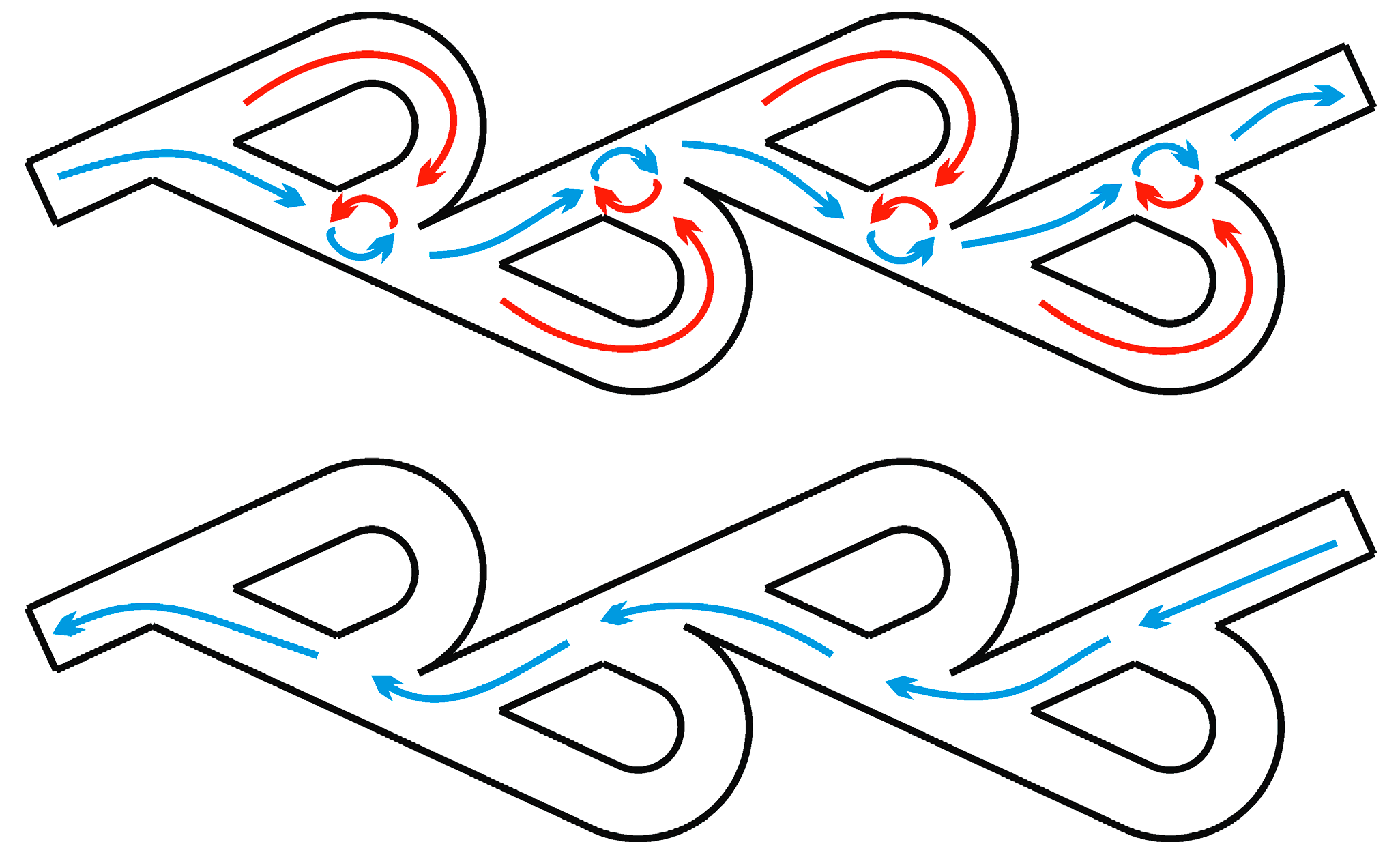
Figure 1: Schematic representation of the operating principle of the Tesla valve operating principle.
2 Reverse Energy Flows in 2D Photonic Crystal with Air Holes
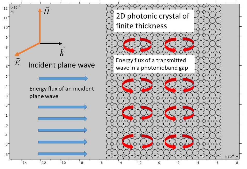
Let us consider the incidence of TE and TM polarized plane waves on a finite two-dimensional photonic crystal with parameters described in the classical work [19]. The square lattice photonic crystal consists of air holes with an air-filling fraction of
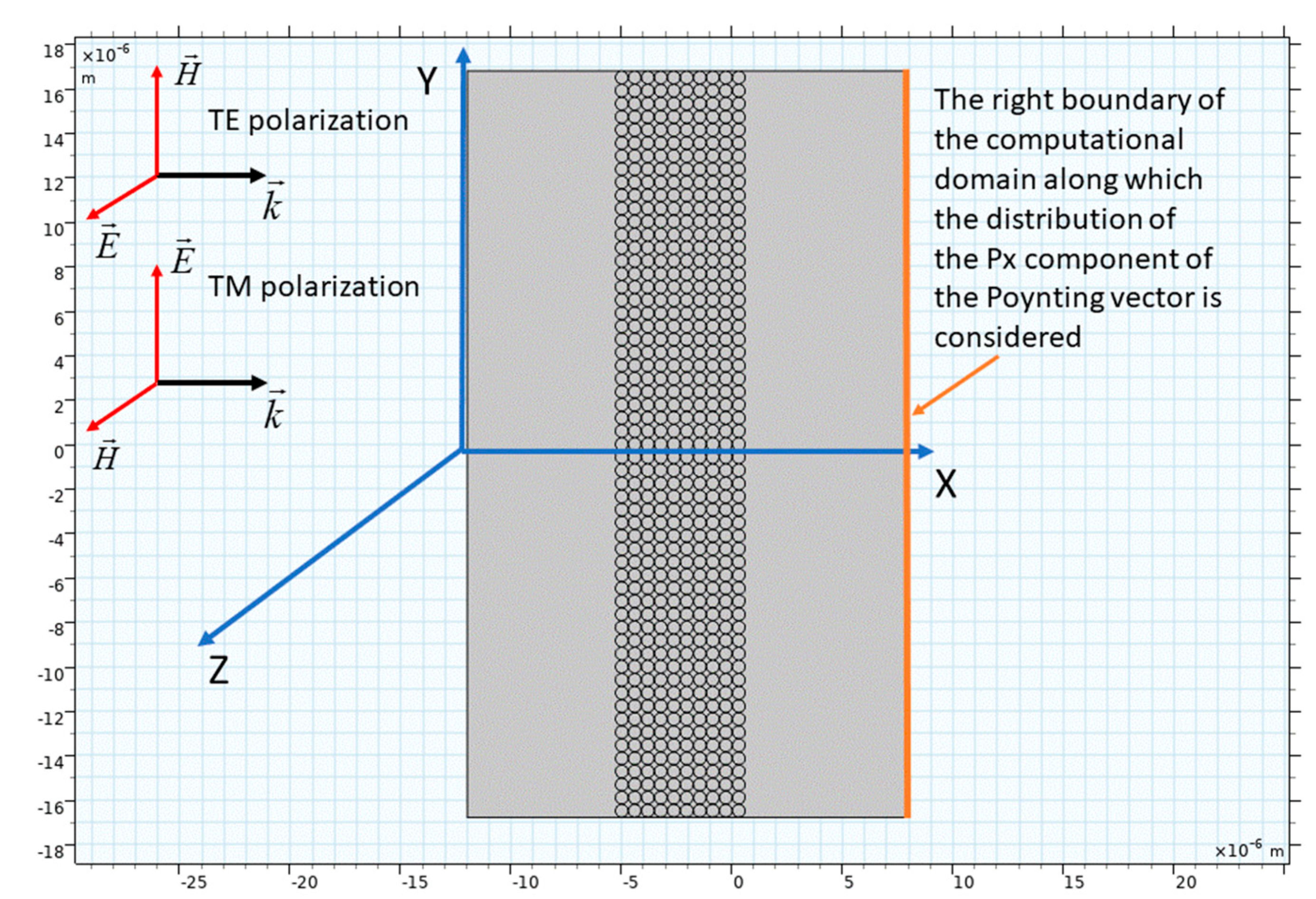
Figure 2: A two-dimensional photonic crystal of finite thickness on which TE and TM polarized plane waves fall from the left.
According to the results in [19], the normalized frequency values of 0.38 for the TM polarized incident plane wave (the electric field is directed along the vertical axis Y (Fig. 2)) and for the TE polarized wave (the electric field is directed along Z-axis (Fig. 2)) lie in the photonic band gap region (Fig. 3). The normalized frequency value of 0.5 is outside the photonic band gap for both polarization of incident plane waves, as it can be seen from Fig. 3.
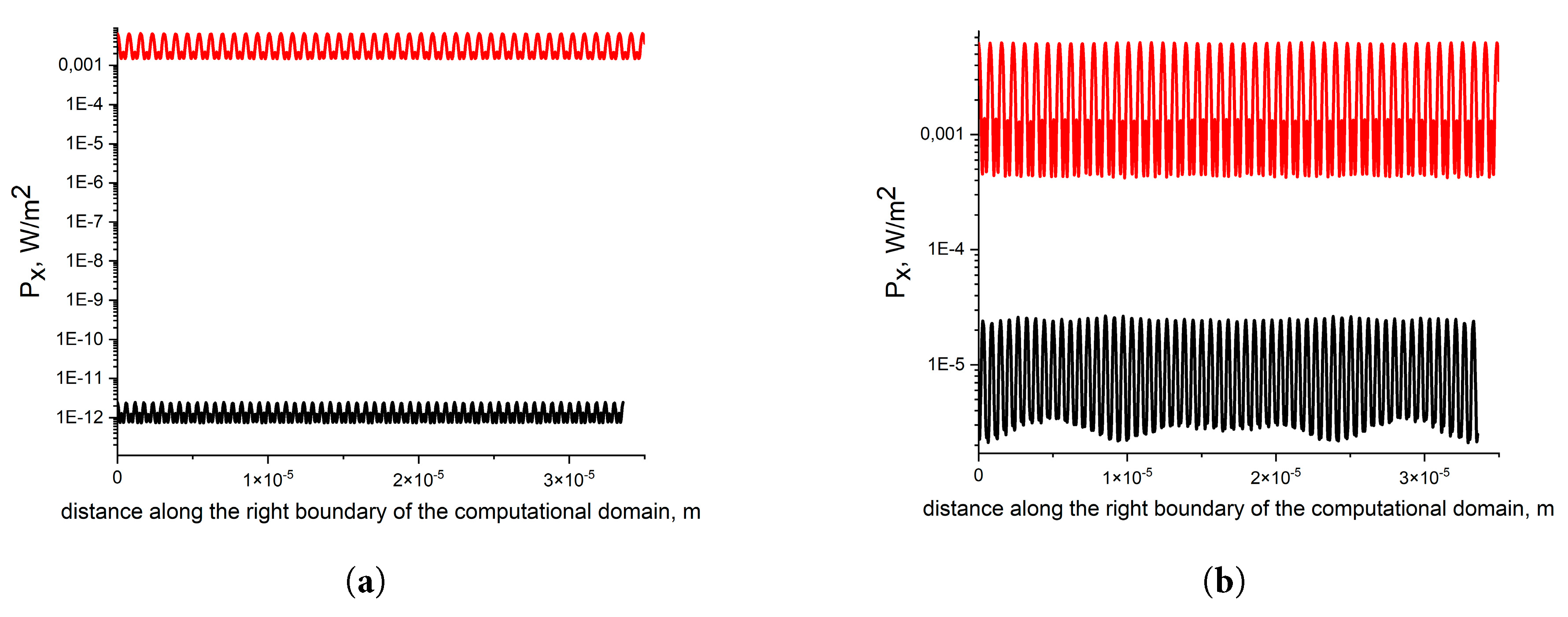
Figure 3: (a) Distribution of the
Let us consider the process of formation of photonic band gaps via the energy flows behavior of the plane wave incident on a 2D photonic crystal slab. It is obvious that to characterize the energy flows both inside and outside photonic band gaps, it is necessary to consider the Poynting vector
As it can be seen from Fig. 4 and Fig. 5, the interference of the incident and reflected waves leads to the formation of curves
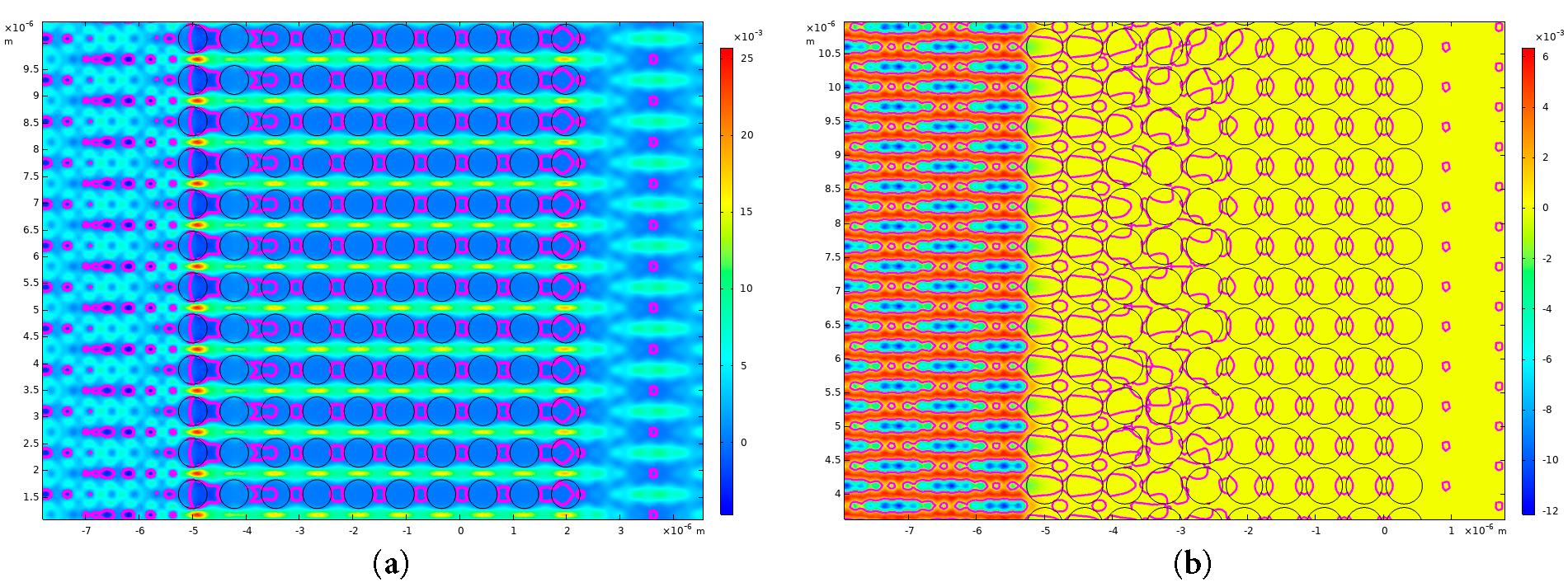
Figure 4: (a) Distribution of the
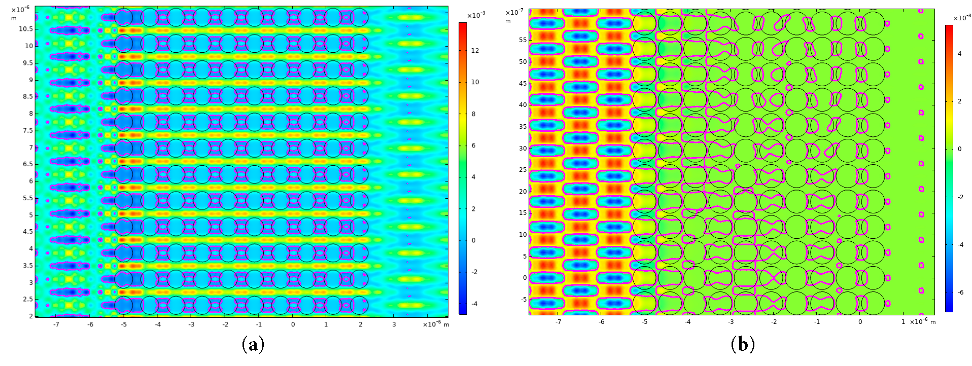
Figure 5: (a) Distribution of the
As in the case of hollow—core fibers with negative curvature of the core-cladding boundary [9], reverse flows of radiation energy must arise due to the presence of vortex motions of the Poynting vector. Since the Poynting vector is a vector, when all its components are simultaneously zero at a given point in space, the direction of the Poynting vector becomes undefined, and a singularity arises. So a Poynting vector vortex may form around this singularity. In our case, the Poynting vector has one component
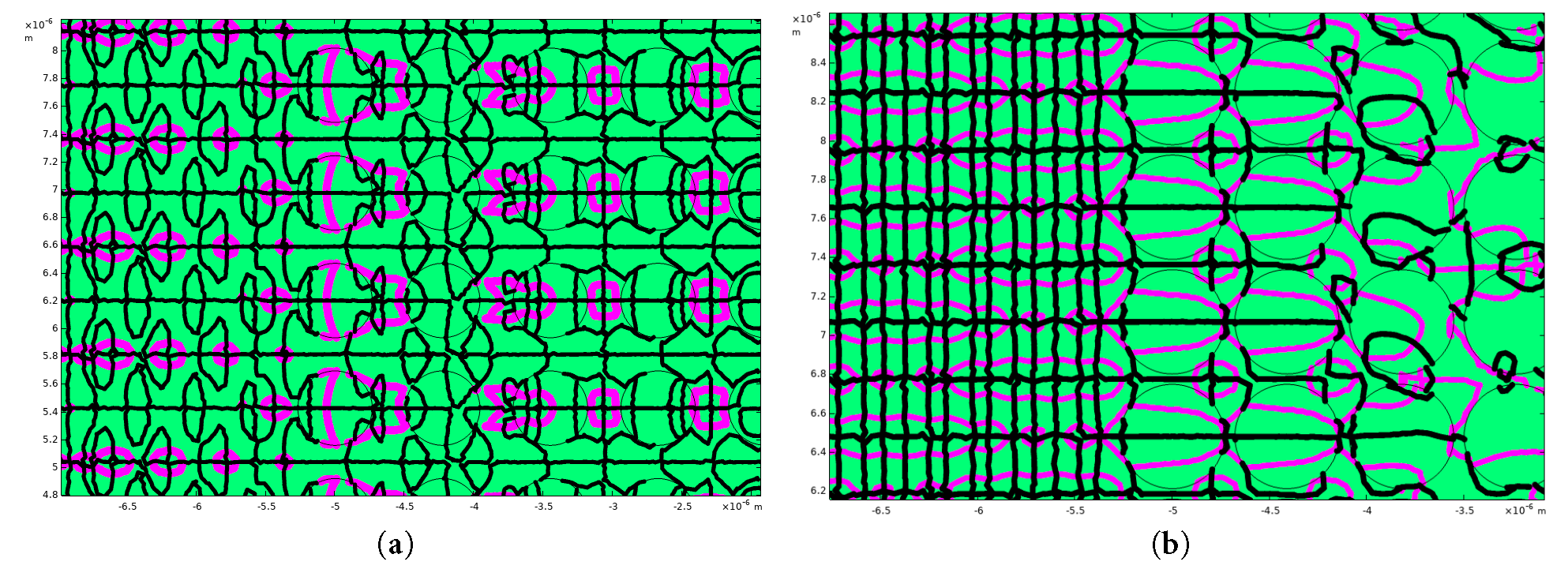
Figure 6: (a) Curves
It is clear from Fig. 6 that it is at the intersection points of these curves that the reverse flows of radiation energy are formed (Fig. 4). Thus, it is the singularities and the corresponding vortices of the Poynting vector of the transmitted and reflected waves that are the cause of the formation of reverse energy flows in the considered photonic crystal slabs with air holes. As can be seen from Fig. 6, the arrangement of vortices in the cross-section of the photonic crystal is directly related to the modes of weak or strong radiation transmission through the photonic crystal slab.
As was indicated in the Introduction, the formation of Poynting vector vortices in 2D photonic crystals may be analogous to vortices formed in a moving fluid flow. The photonic band gap acts as a kind of “barrier” or “forbidden zone” for certain frequencies, analogous to a fluid dynamic system where flow is blocked or redirected by obstacles or changes in boundary conditions. Energy can be carried in fluids by pressure variations or swirling motion and vortices can create areas of low pressure at their cores and higher pressure around them, which disrupts the smooth, forward movement of the liquid and slows down its flow. Within the band gap, the emergence of Poynting vector vortices leads to the blocking or localization of electromagnetic energy flow, much like how fluid vortices can inhibit or redirect fluid motion. Let us consider the distribution of the Poynting vector streamlines (Fig. 7) for the case of photonic crystal slabs shown in Fig. 4.
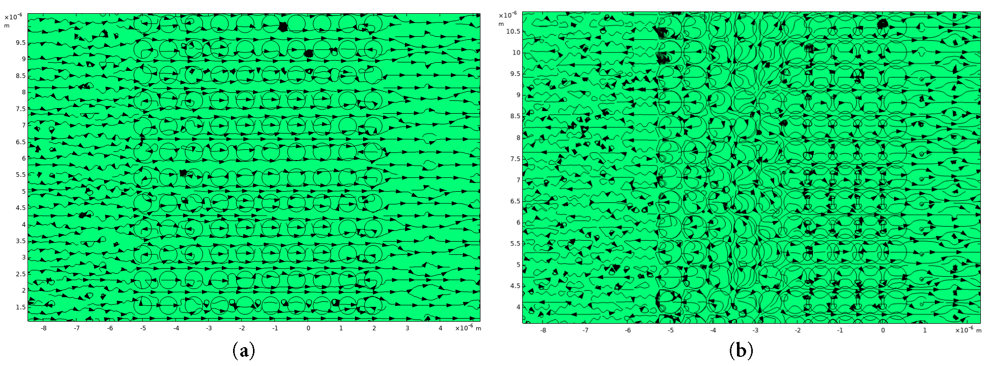
Figure 7: (a) Streamlines of
In the case of strong radiation transmission of the incident TM polarized plane wave, the streamlines of the Poynting vector (Fig. 4a), although deviating from the rectilinear path in the photonic crystal slab, do not form vortices and reverse energy flows in the regions between the air holes (Fig. 7a). Therefore, the energy of the electromagnetic wave is transferred freely through these channels inside the photonic crystal slab. While in the photonic band gap (Fig. 4b) the streamlines of the Poynting vector twist, forming reverse energy flows in the regions between the air holes of the photonic crystal, thereby reducing the radiation transmission of the incident wave through the photonic crystal slab (Fig. 7b). Thus, this behavior is analogous to that of fluid dynamic systems in which fluid vortices can inhibit or redirect fluid motion. In our case, the Poynting vector vortices formed between the rows of air holes and outside the photonic crystal slab perform the same function for the energy flow of the incident plane wave.
To make the analogy between fluid motion in hydrodynamics and energy flow in 2D photonic crystals clearer, let us consider a quantity called vorticity. In a steady plane motion of a fluid, the velocity of a particle
Since in this paper we study the vortex behavior of the Poynting vector for electromagnetic plane waves (also with the harmonic time dependence for wave field components
3 Reverse Energy Flows in 2D Photonic Crystal with Dielectric Rods
As a second example of reverse energy flows occurring in 2D photonic crystals, let us consider the photonic crystal from the work [21] where dielectric rods with a high refractive index surrounded by air are located at the nodes of a square lattice. The parameters of the photonic crystal are
Based on the results of the work [21], a photonic crystal with a rod radius r = 0.315 μm and a distance between the rods a = 1.75 μm was chosen. These parameters of a photonic crystal allow one to obtain a complete photonic band gap for TE polarized incident plane wave at a wavelength of 5 μm, with a wavelength of 2.78 μm and 3.5 μm, both outside the photonic band gap. We plotted the distribution of the Poynting vector
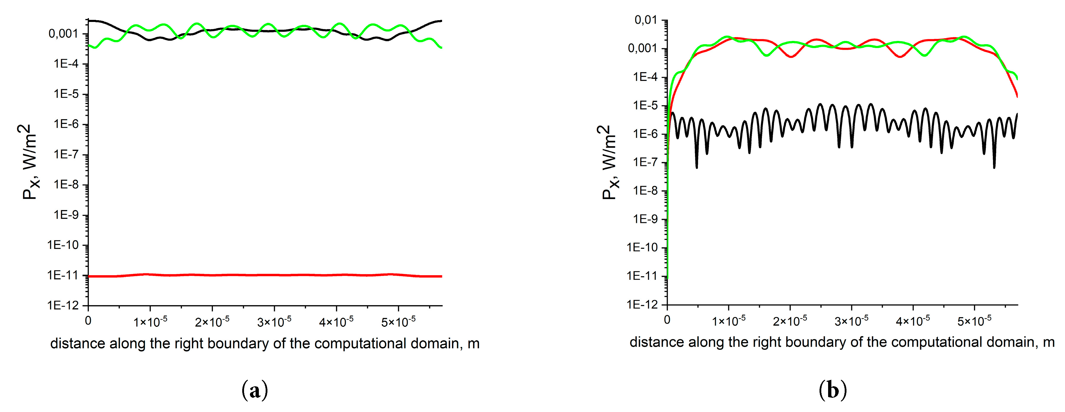
Figure 8: (a) Distribution of the
The distribution of the Poynting vector
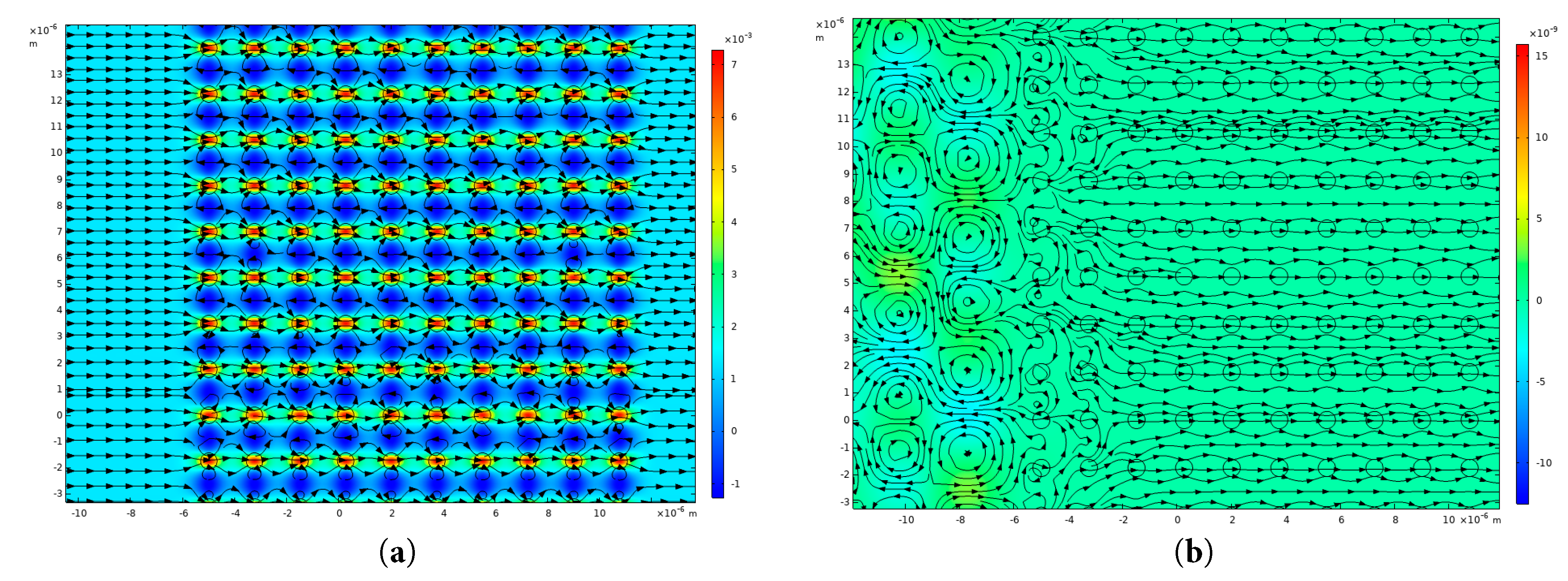
Figure 9: (a) Streamlines of the Poynting vector
As it can be seen from Fig. 9a, the reverse energy flows at a wavelength of 2.78 μm are observed only in the areas between the layers of rods of the photonic crystal slab. The distribution of the Poynting vector streamlines shows that the main part of the radiation passes through the rods and there are no vortices outside the photonic crystal slab. For a photonic band gap at a wavelength of 5 μm (Fig. 9b), the Poynting vector streamlines form a vortex structure in the region in front of the photonic crystal slab. This leads to a sharp drop in the radiation transmission through the photonic crystal slab (Fig. 8a). For a TM polarized incident plane wave, the transmission of radiation through a photonic crystal slab has large values at wavelengths of 5 μm and 3.5 μm (Fig. 8b).
This is confirmed by the behavior of the Poynting vector streamlines shown in Fig. 10. From Fig. 10, it is evident that in this case, with strong radiation transmission through the photonic crystal slab, there are no reverse flows or vortex movements of energy.
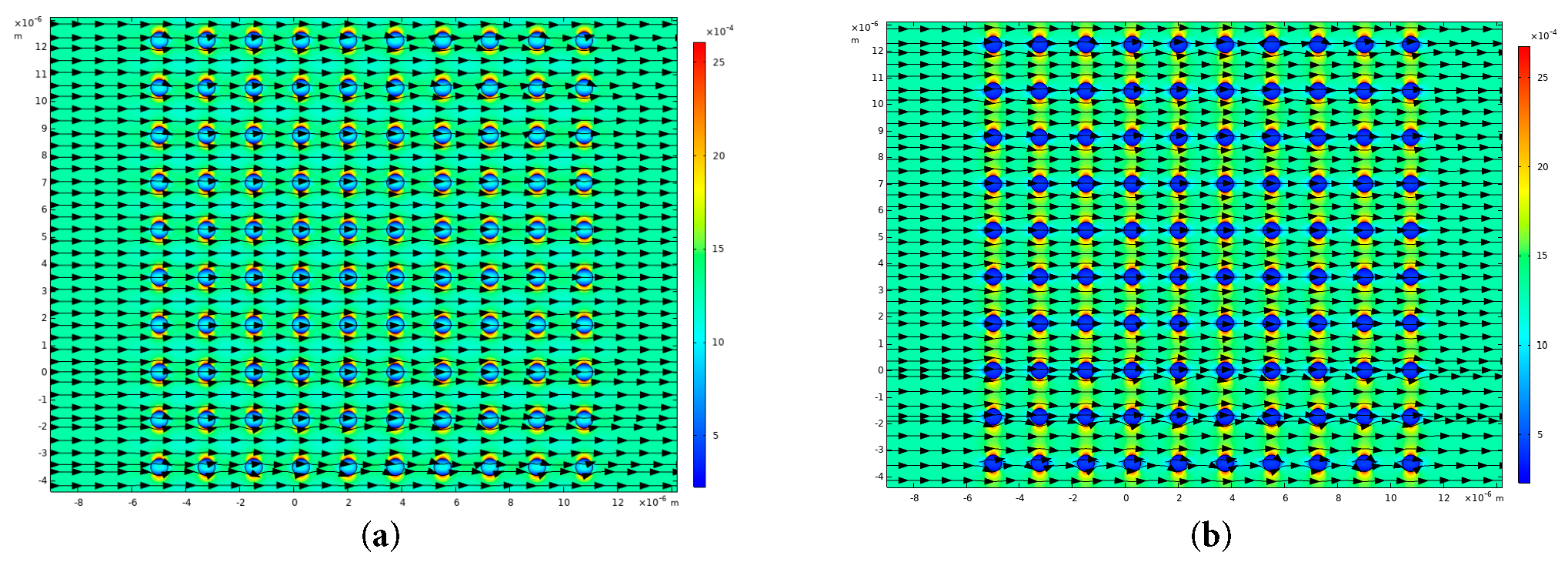
Figure 10: (a) Streamlines of the Poynting vector
The situation with radiation transmission changes qualitatively if we consider the incidence of TM polarized plane wave at a wavelength of 2.78 μm (Fig. 8b).
In this case, the Poynting vector streamlines begin to twist (Fig. 11a) forming reverse energy flows as is in the case of a complete photonic band gap for a TE polarized incident plane wave (Fig. 8a). This behavior of the energy flow is caused by Poynting vector vortices, whose centers lie at the intersection of curves
Thus, it can be argued that the formation of photonic band gaps in 2D photonic crystals is accompanied by the emergence of vortex motions of the Poynting vector for reflected and transmitted radiation. This in turn leads to the formation of reverse flows of electromagnetic field energy in certain areas of the photonic crystal cross-section.
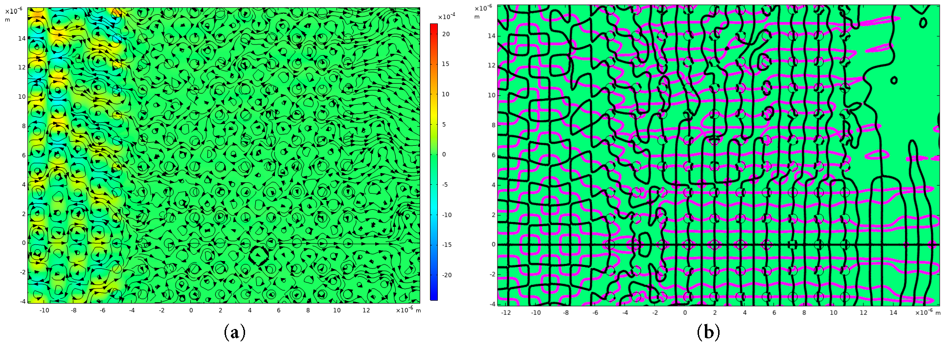
Figure 11: (a) Streamlines of the Poynting vector
In this paper, we considered the transmission of TM and TE polarized plane waves through photonic crystal slabs whose optical properties were obtained in previous studies. Calculations confirmed the presence of photonic band gaps in the required spectral regions. By analogy with hydrodynamics, in which the flow of fluids is characterized by velocity vectors, we examined the behavior of the Poynting vector for propagating electromagnetic radiation in photonic crystal slabs. It turned out that, as is in the case of a fluid encountering obstacles, vortices—regions of swirling flow—can arise in the distribution of the Poynting vector, which in turn generate reverse flows of electromagnetic radiation energy. The decrease in the transmission of electromagnetic radiation through photonic crystal slabs (photonic band gaps) is characterized by the formation of reverse energy flows and Poynting vector vortices. Moreover, this is true for different types of two-dimensional photonic crystals. Therefore, while the physics and governing equations differ (Maxwell’s equations for electromagnetic waves vs. Navier-Stokes equations for fluid flow), the conceptual framework of vector fields, vortex formation, and reverse flow provides a meaningful analogy. This analogy can inspire new ways to understand, visualize, and model complex electromagnetic phenomena by borrowing insights and mathematical tools from classical fluid dynamics.
Acknowledgement:
Funding Statement: The author received no specific funding for this study.
Availability of Data and Materials: The data that support the findings of this study are available from the Corresponding Author, Andrey Pryamikov, upon reasonable request.
Ethics Approval: Not applicable.
Conflicts of Interest: The author declares no conflicts of interest.
References
1. Novitsky AV , Novitsky DV . Negative propagation of vector Bessel beams. J Opt Soc Am A. 2007; 24( 9): 2844. doi:10.1364/JOSAA.24.002844. [Google Scholar] [CrossRef]
2. Kotlyar VV , Kovalev AA , Nalimov AG . Energy density and energy flux in the focus of an optical vortex: Reverse flux of light energy. Opt Lett. 2018; 43( 12): 2921– 4. doi:10.1364/OL.43.002921. [Google Scholar] [CrossRef]
3. Yuan G , Rogers ETF , Zheludev NI . “Plasmonics” in free space: Observation of giant wavevectors, vortices, and energy backflow in superoscillatory optical fields. Light Sci Appl. 2019; 8: 2. doi:10.1038/s41377-018-0112-z. [Google Scholar] [CrossRef]
4. Yan W , Gao Y , Yuan Z , Long X , Chen Z , Ren ZC , et al. Energy-flow-reversing dynamics in vortex beams: OAM-independent propagation and enhanced resilience. Optica. 2024; 11( 4): 531. doi:10.1364/OPTICA.517474. [Google Scholar] [CrossRef]
5. Lu W , Zhou J , Zhang Y , Shi P , Yuan X , Min C . Controllable three-dimensional helical energy backflow in an optical focusing field. Opt Lett. 2024; 49( 21): 6009– 12. doi:10.1364/OL.540915. [Google Scholar] [CrossRef]
6. Saari P , Besieris IM . Energy backflow in unidirectional monochromatic and space–time waves. Photonics. 2024; 11( 12): 1129. doi:10.3390/photonics11121129. [Google Scholar] [CrossRef]
7. Li H , Cao Y , Zhou LM , Xu X , Zhu T , Shi Y , et al. Optical pulling forces and their applications. Adv Opt Photon. 2020; 12( 2): 288. doi:10.1364/AOP.378390. [Google Scholar] [CrossRef]
8. Søndergaard T , Dridi KH . Energy flow in photonic crystal waveguides. Phys Rev B. 2000; 61( 23): 15688– 96. doi:10.1103/PhysRevB.61.15688. [Google Scholar] [CrossRef]
9. Pryamikov A , Alagashev G , Falkovich G , Turitsyn S . Light transport and vortex-supported wave-guiding in micro-structured optical fibres. Sci Rep. 2020; 10( 1): 2507. doi:10.1038/s41598-020-59508-z. [Google Scholar] [CrossRef]
10. Andersen JM , Voitiv AA , Siemens ME , Lusk MT . Hydrodynamics of noncircular vortices in beams of light and other two-dimensional fluids. Phys Rev A. 2021; 104( 3): 033520. doi:10.1103/PhysRevA.104.033520. [Google Scholar] [CrossRef]
11. Voitiv AA , Andersen JM , Ford PC , Lusk MT , Siemens ME . Hydrodynamics explanation for the splitting of higher-charge optical vortices. Opt Lett. 2022; 47( 6): 1391– 4. doi:10.1364/OL.447014. [Google Scholar] [CrossRef]
12. Andersen JM , Voitiv AA , Ford PC , Siemens ME . Amplitude structure of optical vortices determines annihilation dynamics. J Opt Soc Am A. 2023; 40( 2): 223– 8. doi:10.1364/JOSAA.475907. [Google Scholar] [CrossRef]
13. Marmanis H . Analogy between the Navier–Stokes equations and Maxwell’s equations: Application to turbulence. Phys Fluids. 1998; 10( 6): 1428– 37. doi:10.1063/1.869762. [Google Scholar] [CrossRef]
14. Arbab AI . Is the electromagnetic field in a medium a fluid or a wave? Optik. 2017; 130: 154– 61. doi:10.1016/j.ijleo.2016.10.130. [Google Scholar] [CrossRef]
15. Jamati F . Analogy between vortex waves and EM waves. Fluid Dyn Res. 2018; 50( 6): 065511. doi:10.1088/1873-7005/aae16a. [Google Scholar] [CrossRef]
16. Tripodi G , Ruta G . Maxwell’s early unitary view of electricity and fluid mechanics. Encyclopedia. 2024; 4( 1): 13– 25. doi:10.3390/encyclopedia4010002. [Google Scholar] [CrossRef]
17. Onorato M , Baronio F , Conforti M , Chabchoub A , Suret P , Randoux S . Hydrodynamics and optical waves: A common approach for unidimensional propagation. In: Onorato M , Resitori S , Baronio F , editors. Rogue and shock waves in nonlinear dispersive media. Lecture notes in physics. Vol. 926. Cham, Switzerland: Springer; 2025. doi:10.1007/978-3-319-39214-1_1. [Google Scholar] [CrossRef]
18. Huang X , Anufriev R , Jalabert L , Watanabe K , Taniguchi T , Guo Y , et al. A graphite thermal Tesla valve driven by hydrodynamic phonon transport. Nature. 2024; 634( 8036): 1086– 90. doi:10.1038/s41586-024-08052-1. [Google Scholar] [CrossRef]
19. Villeneuve PR , Piche´ M . Photonic band gaps in two-dimensional square and hexagonal lattices. Phys Rev B. 1992; 46( 8): 4969– 72. doi:10.1103/PhysRevB.46.4969. [Google Scholar] [CrossRef]
20. Burr KP . Marine hydrodynamics. Lecture 9. Cambridge, MA, USA: MIT Lectures; 2005. [Google Scholar]
21. Mekis A , Chen JC , Kurland I , Fan S , Villeneuve PR , Joannopoulos JD . High transmission through sharp bends in photonic crystal waveguides. Phys Rev Lett. 1996; 77( 18): 3787– 90. doi:10.1103/PhysRevLett.77.3787. [Google Scholar] [CrossRef]
Cite This Article
 Copyright © 2026 The Author(s). Published by Tech Science Press.
This work is licensed under a Creative Commons Attribution 4.0 International License , which permits unrestricted use, distribution, and reproduction in any medium, provided the original work is properly cited.
 Downloads
 Citation Tools