
 Login
Login Register
 Submit a Paper
 Propose a Special lssue
 Open Access
REVIEW
Active Cooling Technologies for Hypersonic Vehicles: Challenges, Advances, and Future Prospects
1 College of Mechanical Engineering, Hunan University of Arts and Science, Changde, China
2 Hunan Gaochuang Xiangyu Technology Co., Ltd., Changde, China
* Corresponding Author: Liang Yin. Email:
Fluid Dynamics & Materials Processing 2026, 22(9), 11 https://doi.org/10.32604/fdmp.2026.085289
Received 08 May 2026; Accepted 08 September 2026; Issue published 28 September 2026
 View Full Text
 Download PDF
Abstract
Hypersonic vehicles are subjected to extreme aerodynamic heating, making active cooling technologies a critical component of their thermal protection systems. This paper presents a comprehensive review of the fundamental principles, operating mechanisms, recent research developments, and key technical challenges associated with three major active cooling approaches: regenerative cooling, gas film cooling, and transpiration cooling. The review establishes a comparative framework to support the selection of cooling strategies according to specific mission requirements, while identifying current limitations and outlining priorities for future research. The analysis shows that regenerative cooling is well suited to long-duration missions owing to its high heat removal capability, although it requires complex structural integration. Gas film cooling offers a relatively simple and effective solution but demands a substantial coolant supply, which can reduce overall system efficiency. Transpiration cooling exhibits significant potential for next-generation hypersonic vehicles because of its exceptional thermal protection performance, yet its implementation remains constrained by demanding material and manufacturing requirements. Future advances are expected to arise from hybrid cooling architectures that combine the strengths of multiple techniques, together with intelligent thermal management systems capable of adapting to highly variable operating conditions.Keywords
Conquering near space and achieving rapid global reach along with efficient access to space represent a strategic high ground in the aerospace sector of the 21st century. Hypersonic vehicles serve as the core carriers for realizing this objective [1]. However, overcoming the “thermal barrier” stands as one of the most formidable physical challenges that must be addressed on their developmental trajectory [2,3,4,5]. When an aircraft operates at a Mach number of 5 or higher, either within or traversing through the atmosphere, intense aerodynamic compression and viscous dissipation effects irreversibly convert substantial amounts of kinetic energy into thermal energy. The immediate consequence is the generation of extreme aerodynamic heating environments at critical components of the aircraft, such as the nose, leading edge, inlet lip, combustion chamber wall, and control rudder surface. Point temperatures can easily exceed 2000°C, while local heat flux densities may reach several megawatts or even tens of megawatts (MW/m2) per square meter [6,7,8]. Fig. 1 gives the effective operating range of each aerospace propulsion system [9]. This magnitude of heat load significantly surpasses the tolerance limits of conventional aerospace materials. In absence of effective thermal protection measures, structural failure will occur in an exceedingly short time due to softening, melting, oxidation, and even ablation—resulting in catastrophic [10].
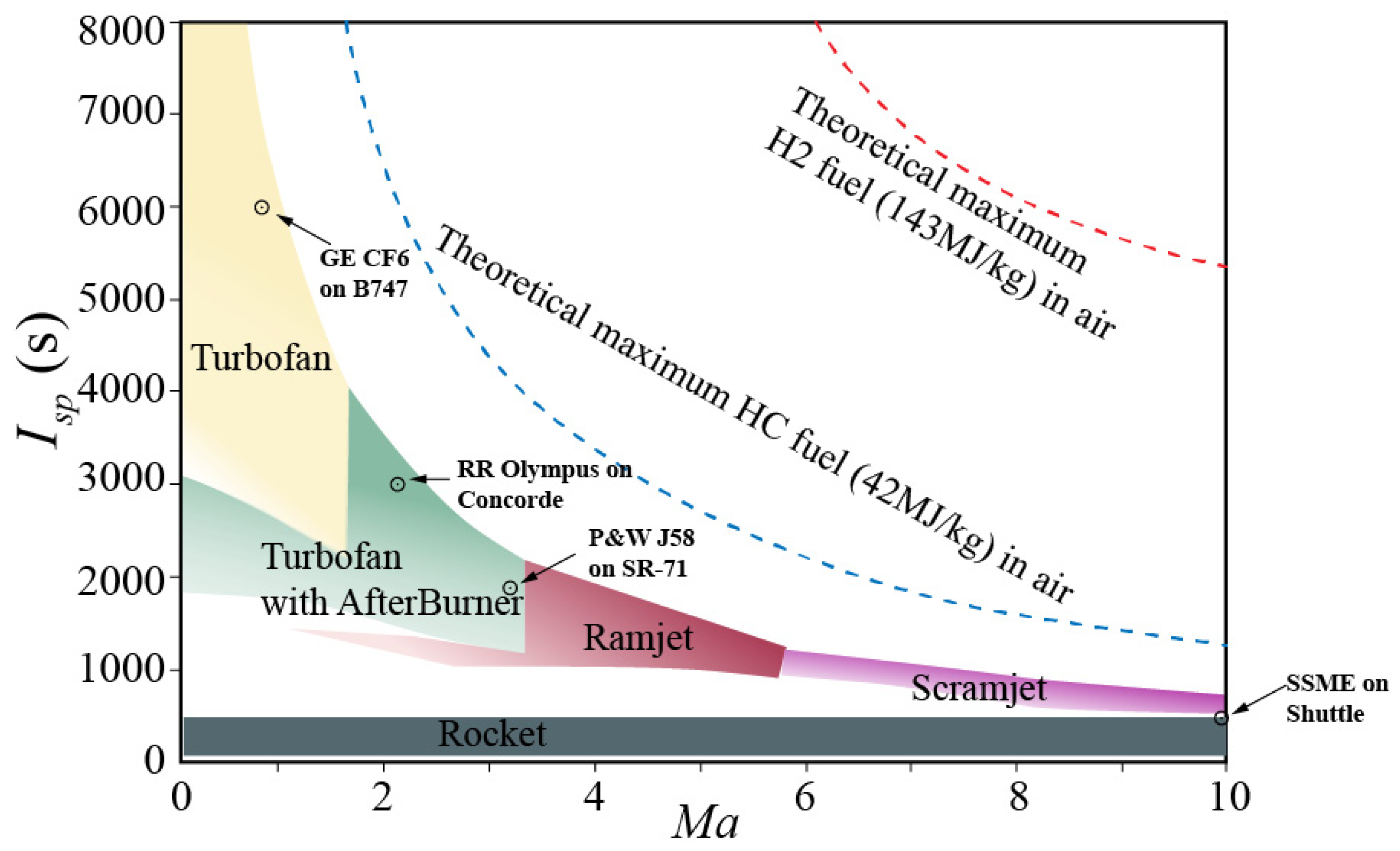
Figure 1: Effective operating range of each aerospace propulsion system.
In the context of such an extreme thermal environment, the thermal protection system serves as a critical lifeline for ensuring the safe operation of hypersonic vehicles. Typical thermal protection strategies for these vehicles can be categorized into three distinct methods: passive, semi-passive, and active [7,11,12].
Passive thermal protection provides cooling for the internal structures of aircraft through the use of heat-resistant materials, insulating materials, and specialized structural designs. This approach primarily encompasses three techniques: insulation, heat sinks, and thermal structures [13,14,15]. Thermal insulation structures are predominantly employed in scenarios characterized by medium heat flux density and short operational durations. Their surfaces effectively dissipate most aerodynamic heat to the external environment via radiation while preventing inward conduction through an insulating layer. Consequently, only a minimal amount of heat penetrates into the secondary layer structure. This method not only efficiently regulates temperature but also preserves aerodynamic shape integrity. The heat sink structure capitalizes on the material’s inherent heat capacity to absorb and store a significant portion of incoming heat; only a small fraction is released through radiation. Its ability to retain heat is closely linked to factors such as specific heat capacity, density, and structural thickness of the material used. While this method features a straightforward and reliable design that maintains aerodynamic shape, its thermal control efficiency tends to be relatively low. Increasing thickness may enhance performance but also adds weight to the structure—an unfavorable outcome for high-load flight missions [16,17]. The thermal structure employs a high-temperature resistant skin that is coated with a high-emissivity finish. During the pneumatic heating process, heat is dissipated into the environment through intense radiation until equilibrium is achieved between the surface radiant heat and the pneumatic heating heat. This approach is not constrained by heating duration, allowing for continuous thermal protection while maintaining aerodynamic shape; however, it does have a maximum thermal load limit [18,19]. Three typical passive thermal protection structures are illustrated in Fig. 2. As shown in Fig. 2a, ceramic heat-resistant tiles provide effective thermal insulation for regions subjected to moderate heat flux and short-duration missions, with their surfaces radiating most aerodynamic heat back to the external environment. As shown in Fig. 2b, flexible heat insulation felt offers lightweight and adaptable thermal protection, featuring low thermal conductivity and ease of installation on curved surfaces. Fig. 2c presents the third and fourth generation super heat-resistant alloy honeycomb sandwich structure, which achieves high strength-to-weight ratios and superior high-temperature capability, making it suitable for more demanding thermal environments. It should be noted that the selection among these passive protection strategies must be comprehensively evaluated based on multiple factors, including heat flux conditions, operational duration, weight constraints, and mission-specific requirements [20].
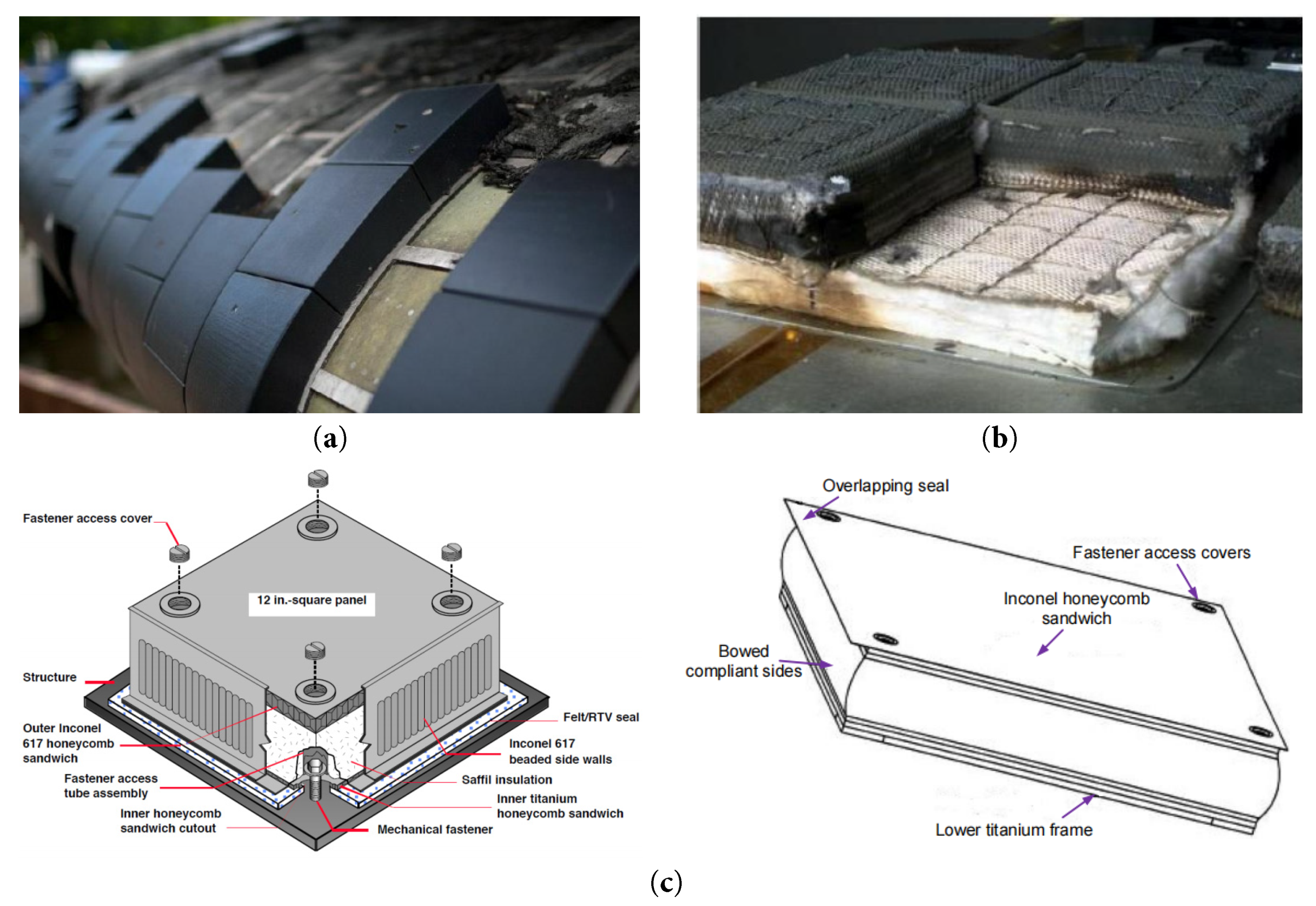
Figure 2: Three passive thermal protection structures; (a) ceramic heat-resistant tiles; (b) flexible heat insulation felt; (c) third and fourth generation super heat-resistant alloy honeycomb sandwich structure.
Under the prolonged influence of high heat flow, passive thermal protection often fails to meet operational requirements, necessitating the adoption of semi-passive methods. These primarily encompass two structural approaches: heat pipes and ablation.
Heat pipe employs a phase change cycle for effective heat transfer, making it particularly suitable for regions experiencing intense localized heating while maintaining relatively lower peripheral temperatures. In this system, the working medium absorbs heat and vaporizes at the hot end; it then flows to the cold end where condensation occurs, releasing heat in the process. Subsequently, through capillary action, it returns to the hot end, thereby establishing a continuous cycle, as illustrated in Fig. 3. This structure frequently incorporates refractory metal heat pipes within composite materials to channel concentrated heat towards low-temperature zones before dissipating it via radiation. Such an arrangement not only preserves optimal aerodynamic shapes but also allows for reuse [21,22,23,24].
Ablative cooling operates by consuming material through its own phase transformation and is particularly suited for extreme aerodynamic heating environments [25,26,27,28]. During ablation, materials undergo various reactions—including decomposition and vaporization—at elevated temperatures that generate gases capable of carrying away substantial amounts of heat. Concurrently, there is a gradual reduction in structural mass along with alterations in surface shape [29], as shown in Fig. 4. While this method can adjust aerodynamic characteristics to some extent, its application is typically limited to single missions or requires repair and reuse; an example being the bottom section of a reentry capsule’s heat shield used in manned spaceflight.
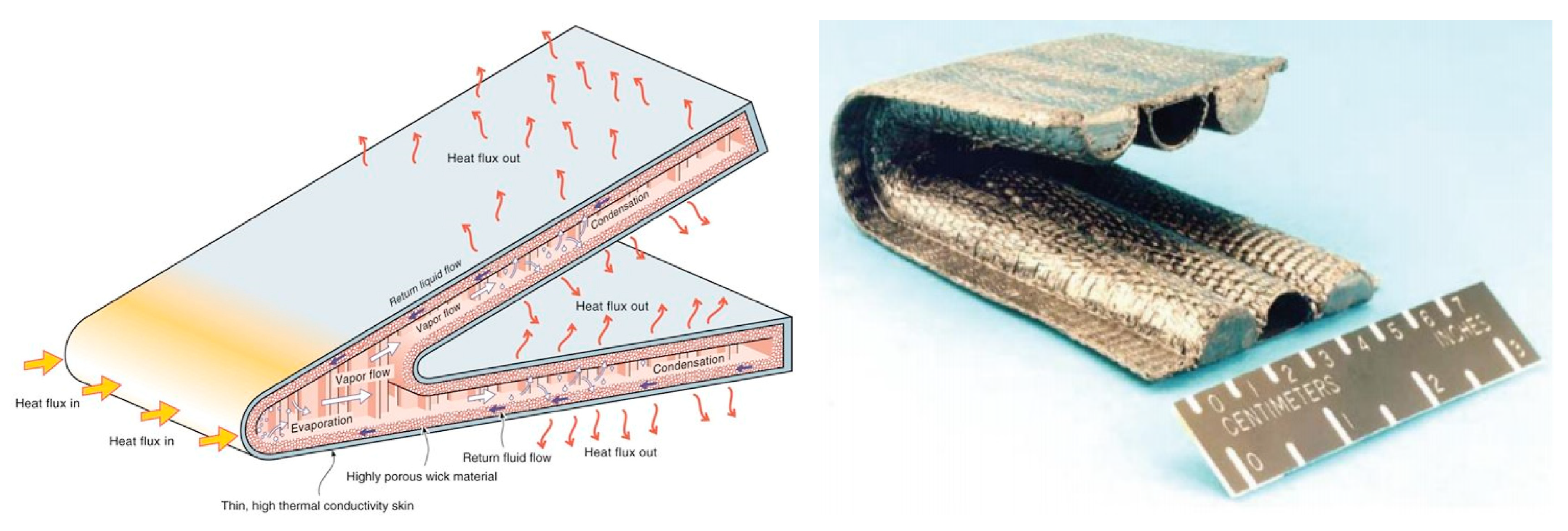
Figure 3: Heat pipe heat protection principle and model.
Both methodologies rely on phase change mechanisms; however, one functions as a closed-loop cycle while the other facilitates consumptive heat dissipation—each targeting distinct scenarios involving reusable systems versus those subjected to singular high thermal loads.
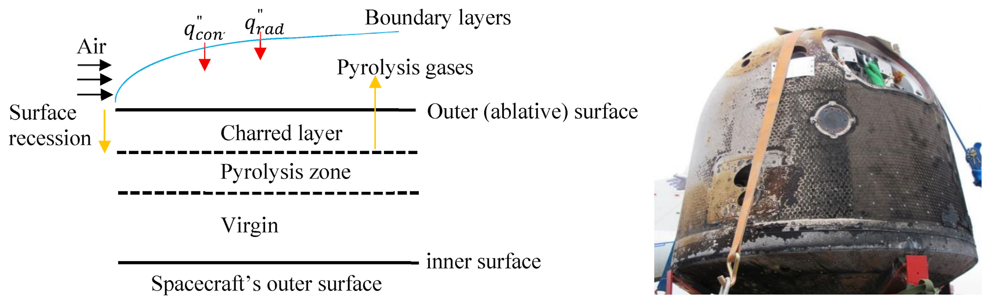
Figure 4: Ablation principle and pictures.
Although passive and semi-passive thermal protection technologies have demonstrated effectiveness and relative simplicity in structure across most space missions, their thermal management capabilities are fundamentally constrained by the inherent properties of materials and one-time phase change processes. These methods are increasingly proving inadequate when confronted with stringent requirements such as extreme heat flux density, prolonged atmospheric re-entry, or reusable aircraft. To overcome these limitations, active thermal protection technology has emerged. The core concept involves a shift from “tolerating and dissipating” heat to “actively managing and transferring” it. By incorporating external energy sources, cooling fluids, or real-time control systems, precise regulation of structural temperature can be achieved, thereby significantly enhancing the thermal survivability and mission adaptability of aircraft. It should be noted that several excellent reviews exist on specific aspects of hypersonic thermal protection systems. For instance, Luo et al. [30] provided a comprehensive review of regenerative cooling technologies tailored specifically to scramjet engines, addressing key phenomena including supercritical heat transfer, pyrolysis, and coking. While such focused reviews deliver in-depth treatment of individual technologies, the present manuscript addresses a distinct gap by offering a broader, comparative perspective—systematically encompassing three major active cooling approaches: regenerative cooling, gas-film cooling, and transpiration cooling—within a unified analytical framework. This holistic approach facilitates rigorous cross-technology comparison and delivers actionable, engineering-oriented guidance for technology selection and system integration.
This article aims to provide a robust theoretical foundation and comprehensive technical references for the design, selection, optimization, and future research directions of hypersonic vehicle thermal protection systems through systematic organization and analysis. This effort seeks to address the “thermal barrier” bottleneck effectively while promoting the practical application process of hypersonic technology.
2.1 Regenerative Cooling Technology
Regenerative cooling technology was first proposed by Tsiolkovsky and subsequently applied to the thrust chambers of rocket engines [31]. Since its inception, regenerative cooling technology has found extensive applications in the aerospace applications, as illustrated in Fig. 5. The early development of this technology can be traced back to the RD-107/108 engine developed by the Soviet Union in the late 1950s. This engine featured a design that allowed kerosene to flow through rectangular brazed steel cooling channels, thereby establishing a foundation for regenerative cooling systems in liquid rockets. Through fuel-staged cooling and a parallel multi-combustion chamber scheme, this technology facilitated over sixty years of continuous operation for rockets ranging from Vostok to Soyuz.
Simultaneously, the Soviet Union/Russia achieved an innovative composite design integrating liquid hydrogen regenerative cooling with radiation-cooled nozzles on the RD-0120 engine used in the Energy rocket. Its helical wound copper alloy lining combined with a stainless steel shell brazed structure is capable of withstanding heat flows up to 20 MW/m2. The legacy of high-pressure pre-combustion chamber cooling technologies has profoundly influenced subsequent developments such as the RD-180/191 series. In the 1990s, under the leadership of TsNIIMash (Central Institute of Mechanical Manufacturing Science), efforts were made towards developing “needle” hypersonic vehicles aimed at validating scramjet engine technologies for Mach numbers between 6 and 14. These engines were designed to incorporate fuel regeneration cooling while utilizing high-temperature resistant materials for their fuselage. Although this project did not reach full completion, it laid critical groundwork for advancements like the “Zircon” missile. The 3M22 “Zircon” hypersonic cruise missile entered service in Russia in 2022 and features a design wherein heat-absorbing hydrocarbon fuel circulates through an integrated cooling channel constructed from ceramic matrix composites (CMC). This configuration provides thermal protection against gas temperatures exceeding 2000°C under conditions corresponding to Mach number greater than 8. Consequently, it has emerged as the world’s first operational hypersonic power system employing fuel-regenerated cooling deployed in actual combat scenarios.
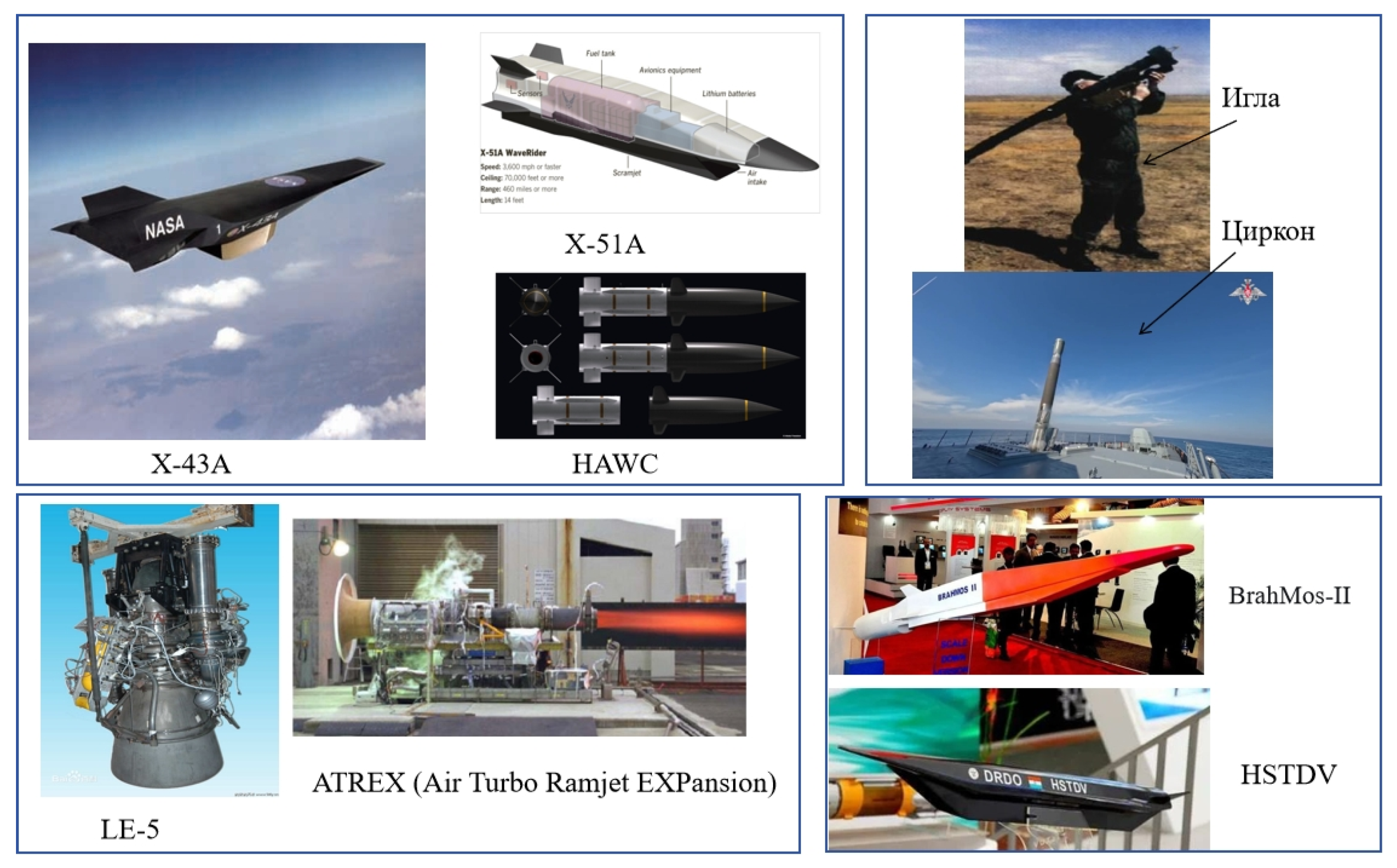
Figure 5: Typical applications of regenerative cooling technology.
The main engine (SSME) of the US Space Shuttle employs a regenerative cooling system utilizing liquid hydrogen as the coolant [32,33]. In May 2010, the X-51A “Wave Rider” demonstrator successfully implemented an ethylene/JP-7 fuel regenerative cooling combustion chamber, achieving a flight duration of 143 s. This milestone indicates that engine regenerative cooling technology in the United States has matured and is progressively advancing into engineering application research. Both DARPA’s “Advanced All-State Engine” (AFRE) project and the Air Force’s “Hypersonic Air-Breathing Weapon Concept” (HAWC) are reliant on this advanced regenerative cooling technology [34].
In 1994, Japan introduced a stepped variable cross-section cooling channel in the LE-7 engine of the H-II rocket to optimize the distribution of liquid hydrogen flow rates and mitigate local overheating. Initially, several test failures occurred due to brazing defects. However, through the development of both the LE-5 and LE-7 engines for the H-II rocket, significant advancements were made in mastering core thermal protection technologies related to high-pressure liquid hydrogen regenerative cooling. By 2001, the LE-7A achieved stable operation through precision machining and material enhancements. As we entered the 21st century, there has been an evolution in regenerative cooling technology driven by demands for hypersonic propulsion that can withstand extreme thermal environments. The Air Turbo Ramjet Engine with Expander Cycle (ATREX) project, collaboratively developed by Japan Aerospace Exploration Agency (JAXA) and Ishikawajima-Harima Heavy Industries Co., Ltd. (IHI), stands out as one of Japan’s most innovative aerospace engine initiatives. At its core is a pre-cooler utilizing liquid hydrogen fuel regeneration cooling capable of reducing incoming air temperatures to 160 K. Additionally, it employs liquid hydrogen regenerative cooling to protect high-temperature components such as combustion chambers.
India is engaged in two hypersonic missile projects: the “BrahMos-2” and the Hypersonic Technology Demonstrator Vehicle (HSTDV). The BrahMos-2 cruise missile shares a similar configuration with Russia’s Zircon hypersonic missile, utilizing the same engine and propulsion technology. Its scramjet engine will incorporate fuel regeneration cooling, likely employing a specialized heat-absorbing hydrocarbon fuel supplied by Russia. The HSTDV is an initiative launched by India’s Defence Research and Development Organisation (DRDO) in 2005, aimed at developing a scramjet engine demonstrator. This project serves as a test platform for evaluating critical technologies necessary for hypersonic flight and represents a fundamental component of India’s hypersonic endeavors. The independently developed scramjet engine is expected to integrate an advanced fuel regeneration cooling system. In successful test flights conducted in 2019 and 2020, powered flights lasting 20 s were achieved, showcasing the effectiveness of its regenerative cooling system and fuel. These accomplishments have positioned India among the select few nations worldwide that have mastered both scramjet engines and independent thermal protection technologies.
Regenerative cooling technology is the most prevalent cooling method employed in hypersonic vehicles [35,36,37]. This technique typically utilizes fuel as the coolant. The coolant effectively removes heat from the combustion chamber wall by circulating through interlayers or channels situated between the inner and outer walls of the combustion chamber, thereby achieving efficient cooling of the combustion chamber wall. Simultaneously, after absorbing heat, the coolant can be reintroduced into the combustion chamber via injectors for subsequent combustion. This process allows energy to be “regenerated”, as illustrated in Fig. 6. The primary advantage of regenerative cooling technology lies in its ability to maintain engine performance without adverse effects. However, excessive pressure drops within the cooling channels may lead to elevated pressures throughout the entire engine system, which could hinder efforts to increase both combustion chamber pressure and overall engine performance.
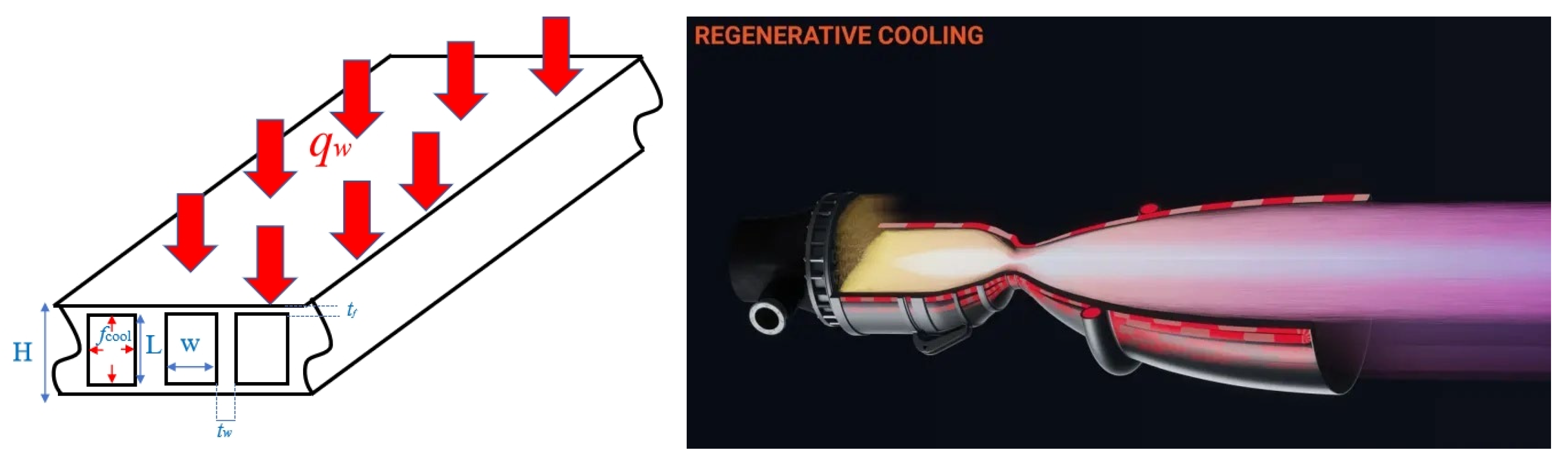
Figure 6: Regenerative cooling technology.
As the flight Mach number increases, the fuel heat sink required for the regenerative cooling of scramjet engines correspondingly rises. At this juncture, it becomes essential to fully leverage the chemical heat sink inherent in the fuel to satisfy the demands of the cooling task. This type of fuel is referred to as endothermic hydrocarbon fuel [38]. However, when used solely as a coolant, fuel possesses a limited capacity for heat absorption. Furthermore, super-combustion ramjet engines operate under extreme thermal loads, which can easily result in scenarios where the ratio of coolant demand flow rate to combustion demand flow rate exceeds Consequently, any excess fuel must be discarded, leading to both waste and degradation in quality.
At present, the conventional approach involves modifying fuel through a catalyst to enhance its heat absorption capacity. However, during the regenerative cooling process, hydrocarbon fuels typically exist in a supercritical state. At this stage, the density, dynamic viscosity coefficient, and specific heat capacity of hydrocarbon fuels undergo significant changes, resulting in highly complex fluid flow, heat transfer, and mass transfer phenomena [39]. This complexity has been extensively investigated in the open literature. In relation to regenerative cooling technology that utilizes hydrocarbon fuels as coolants, researchers worldwide have conducted extensive studies that can be categorized into three main areas:
2.1.1 Research on the Mechanisms of Cracking and Coking in Hydrocarbon Fuels
Coking is a complex series of chemical and physical processes. Based on different coking mechanisms, it can be categorized into thermal oxidation coking and thermal cracking coking. Thermal oxidation coking primarily occurs within the temperature range of 145°C to 425°C. This process arises when dissolved oxygen in the fuel reacts with its components to generate coking precursors, which subsequently initiate a series of free radical chain reactions. Fig. 7 illustrates the transformation process of the oxidized coking material [40]. Jiang [41], Heneghan [42], Katta [43], Doungthip [44], and Kuprowicz [45] have conducted extensive research on the mechanism of kerosene thermal oxidation coking. Their findings indicate that the thermal oxidation coking reaction predominantly results from interactions between various heteroatomic components in kerosene and peroxyl radicals derived from hydrocarbons, followed by further oxidation under conditions rich in dissolved oxygen, leading to the formation of insoluble macromolecular substances. A relatively detailed kinetic model for this oxidative coking chemical reaction has been proposed.
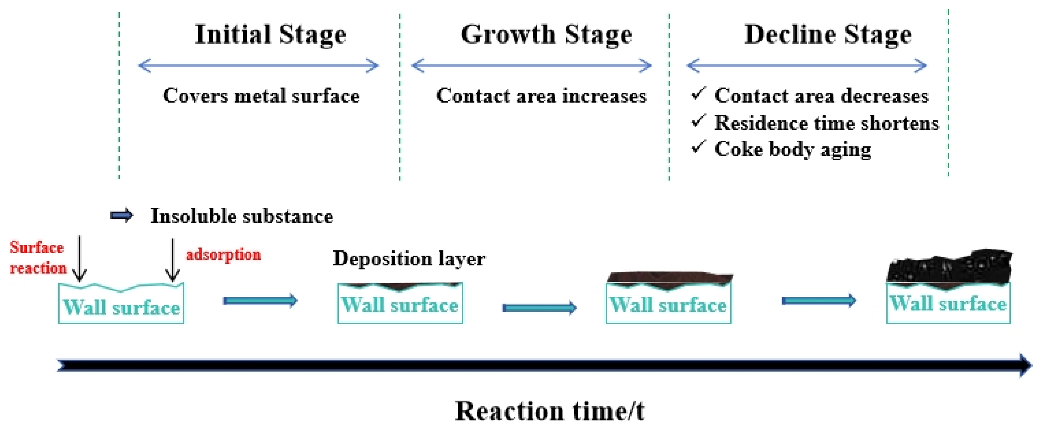
Figure 7: The evolution process of coke structure in the oxidative coking experiment.
When the temperature continues to rise to approximately 425°C, thermal oxidation coking gradually transitions into thermal cracking coking. Currently, research on pyrolysis-induced coking primarily focuses on the development of pyrolysis reaction models and the factors influencing the pyrolysis coking rate. A considerable number of studies have been conducted on this topic in the existing literature. For example, Hou et al. [46] established a comprehensive lumped reaction mechanism for kerosene pyrolysis through experimental investigations, and based on this framework, systematically studied phenomena including kerosene cracking and associated flow and heat transfer characteristics under both supercritical and subcritical conditions in regenerative cooling channels. Jia et al. [47] investigated the thermal cracking behavior of n-decane under varying pressure conditions. The resulting pyrolysis products were identified and analyzed using gas chromatography/mass spectrometry (GC/MS), leading to the proposal of a detailed reaction mechanism involving 164 components and 842 elementary reactions. Fig. 8 shows the scanning electron microscope images of carbon deposit morphologies.
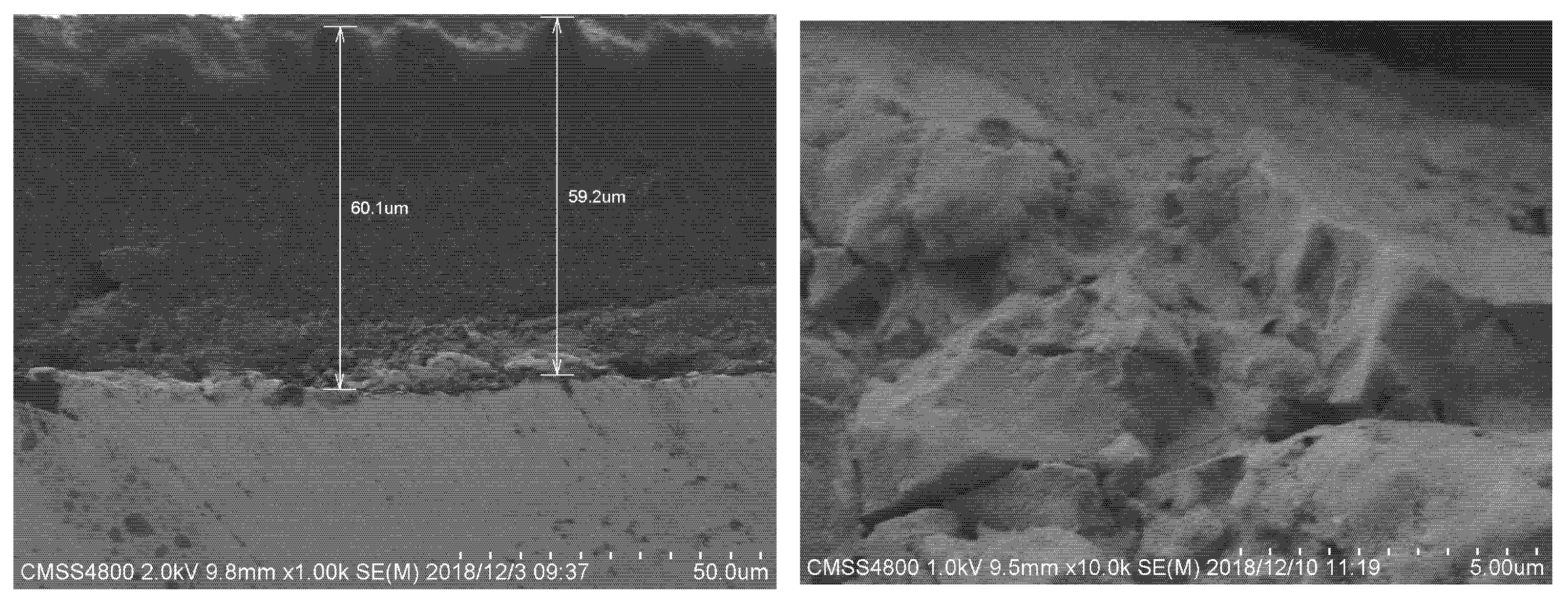
Figure 8: Scanning electron microscope images of carbon deposit morphologies.
At present, several predictive models have been developed to elucidate the mechanism of thermal cracking. For instance, the high-temperature decomposition model for long-chain alkanes, established by the French institutions ONERA and MBDA [48], has been validated across a wide range of temperatures and pressures. Efforts are also underway to incorporate a carbon deposition model into the simulation framework to enhance the accuracy of computational fluid dynamics (CFD) parameter predictions. Depeyre et al. [49] proposed a radical-based reaction mechanism for the thermal cracking of chain alkanes, known as the R-K model. Subsequently, Djimasbe [50] refined the R-K model and introduced the F-S-S mechanism, which has since been corroborated by other researchers. Ward et al. developed a two-dimensional program to simulate the cracking process of hydrocarbon fuels and experimentally validated the cracking behavior and heat transfer characteristics of n-decane and n-dodecane using the Proportional Product Distribution (PPD) chemical model. This model demonstrates high applicability for studying convective heat transfer in n-decane tubes under moderate to low cracking rates; however, its prediction accuracy deteriorates significantly at higher cracking rates. Research on the physical properties of coking products derived from hydrocarbon fuels has also been extensively conducted, primarily through experimental approaches. For example, Lucas et al. [51] determined the density of pyrolytic coke from methane within the temperature range of 1273~1373 K. Similarly, Ji et al. [52] investigated kerosene coking products formed at 800~900 K and experimentally characterized their apparent morphology and key physical property parameters.
2.1.2 Research on Methods for Inhibiting Cracking and Coking in Hydrocarbon Fuels
At present, the solutions to this problem can be categorized into two main approaches. The first involves the addition of specific additives capable of inhibiting kerosene coking. For instance, Taylor et al. [53] introduced trace amounts of sulfides and nitrogen compounds; Jin et al. [54] incorporated organic sulfur- and phosphorus-based coking inhibitors; Strohm et al. [55] added tetrahydronaphthalene at a volume fraction of 2%; Guo et al. [56] utilized organic selenium compounds in conjunction with hydrogen-donating agents to mitigate coking during the cracking process; and Zhang et al. [57] introduced 1% o-methylhydroquinone (THQ). These studies collectively demonstrate that the incorporation of such inhibitors effectively suppresses both surface-catalyzed coking and free radical-mediated coking, thereby reducing the cracking rate and lowering the overall coking tendency.
The second approach focuses on minimizing coking by optimizing operational parameters. Current research indicates that temperature and dissolved oxygen are the most critical factors influencing kerosene coking, with flow regime and operating pressure playing secondary roles. Within the cooling channel, the physical factors affecting oxidation and coking of aviation kerosene include temperature, pressure, flow velocity, and channel geometry. Chemical factors encompass the primary hydrocarbon components, antioxidants, metallic species, sulfides, hydrogen peroxides, and other trace constituents, in addition to temperature, as illustrated in Fig. 9. These factors significantly influence the spatial distribution of coke deposition by modulating chemical reaction pathways, heat transfer efficiency, and mass transfer rates.
The absorption of heat by hydrocarbon fuel in the cooling channel induces a rise in temperature. However, the influence of temperature is highly complex. On one hand, it triggers significant variations in physical properties, thereby affecting the flow behavior of the fuel. On the other hand, temperature serves as a critical parameter in determining the rate constants of chemical reactions and represents one of the most influential factors in the oxidation coking process. Although existing studies have elucidated the effects of key parameters such as temperature and dissolved oxygen on oxidation coking, there remains a lack of coordinated multi-parameter control strategies. In particular, the dynamic equilibrium mechanism under the strong coupling between abrupt high-temperature-induced changes in physical properties and chemical reactions is still not well understood.
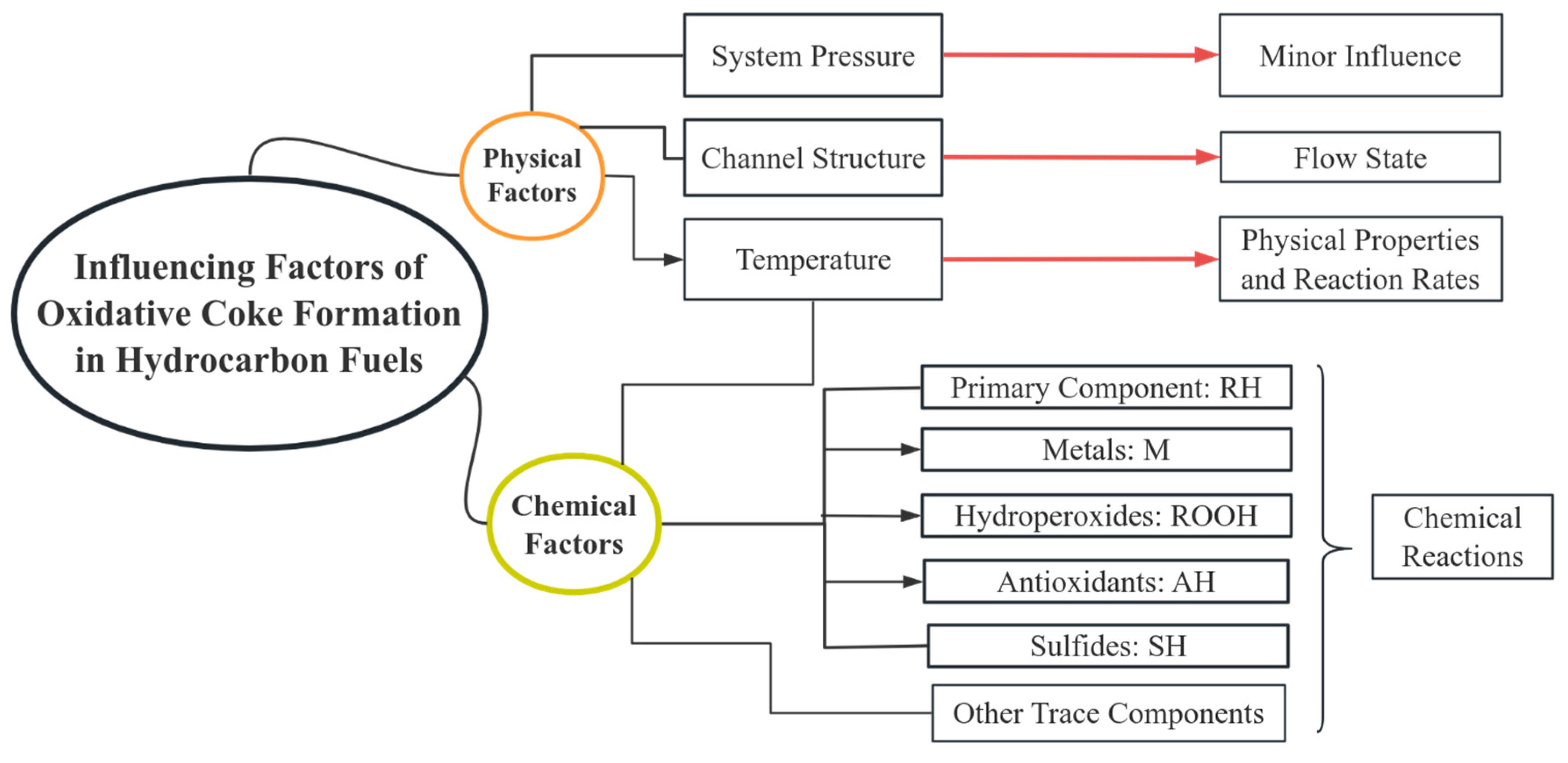
Figure 9: Influencing factors of oxidative coke formation in hydrocarbon fuels.
2.1.3 Research on the Coupling Effect between Coking and Heat Transfer
Regarding the influence of thermodynamic conditions on the coupling of heat transfer and coking, the abrupt variation in physical properties under supercritical pressure has emerged as a key research focus, as illustrated in Fig. 10. The NASA research team found that the reduction in density and viscosity of JP-7 fuel in the supercritical state enhances turbulence, thereby inducing a dynamic equilibrium characterized by periodic spalling and regeneration of the coke layer. When the heat flux density exceeds 1204.6 kW/m2, heat transfer deterioration (HTD) ensues—characterized by a sharp rise in wall temperature and a sudden decline in the heat transfer coefficient. This deterioration arises from the formation of a gas-like thermal boundary layer adjacent to the wall, induced by abrupt variations in thermophysical properties of the supercritical fluid [24], thereby triggering an exponential increase in the coking rate. Flow characteristics also significantly affect coke distribution. A high flow velocity in microchannels can mitigate boundary layer retention, reducing coke deposition by up to 50%. However, in rectangular channels, secondary flows induce localized high-temperature zones at corner regions, where the coking rate is 2~3 times higher than in the central areas [58,59,60,61]. Investigations into the coupled effects of heat transfer and coking have revealed a nonlinear relationship between coke layer thickness and the degradation of the heat transfer coefficient. When the wall temperature surpasses 750°C, the thermal resistance contributed by the coke layer becomes the dominant factor in heat transfer deterioration, resulting in a reduction of over 30% in heat exchange efficiency.
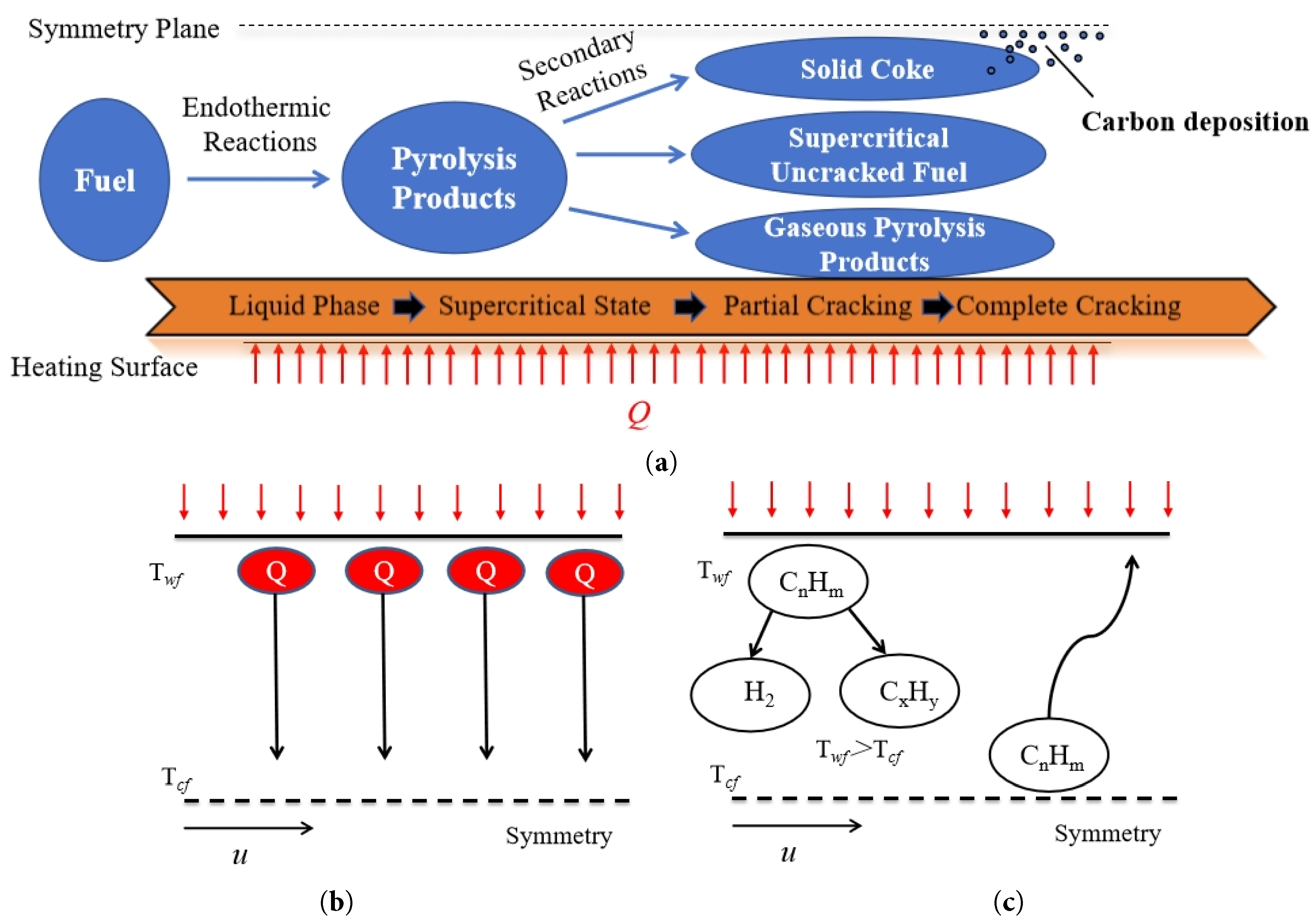
Figure 10: Hydrocarbon fuel cracking coking and multi-physical field coupling relationship: (a) hydrocarbon fuel cracking coking; (b) heat diffuses radially along the channel; (c) components diffuse radially along the channel.
Li et al. [62] verified the disturbance effect of coking on boundary layer flow through microchannel studies, and proposed that the dynamic feedback between the porosity and thermal conductivity of the coke deposit constitutes the core mechanism underlying heat transfer degradation. The Advanced Power Technology group at Harbin Institute of Technology systematically investigated the influence of oxidation-induced cracking reactions on the flow and heat transfer mechanisms of hydrocarbon fuels, and analyzed the non-uniform flow distribution of such fuels in regenerative cooling channels [63,64]. Research conducted by Chang [65], Liu [66], and Feng et al. [67] indicates that when coke deposits form on the wall of a cooling channel, a critical coke thickness exists within the channel. When the deposit thickness is below this critical value, heat exchange performance within the channel is enhanced; however, once the thickness exceeds the critical threshold, heat transfer efficiency deteriorates significantly. Measurement results reported by Taddeo et al. [68] demonstrate that the amount of coke deposited in the cooling channel is primarily influenced by the wall heat flux density. Furthermore, coke formation leads to an increase in wall temperature and a rise in pressure drop across the channel. It is evident that, although existing studies have elucidated the correlation between abrupt changes in supercritical fluid properties and dynamic coking behavior, challenges remain—particularly regarding the lack of quantitative characterization of cross-scale coupling mechanisms and insufficient accuracy in predictive models for critical coking thickness. Recent numerical investigations have also explored geometric enhancements to mitigate heat transfer deterioration. For instance, Shanmugam et al. [69] numerically demonstrated that integrating arc-rib turbulators within regenerative cooling channels can significantly improve the thermal-hydraulic performance of supercritical hydrogen, achieving a wall temperature reduction of 9–28.7% compared to smooth channels. Such passive enhancement techniques offer a complementary approach to active cooling strategies, potentially alleviating the adverse effects of coking and supercritical heat transfer deterioration through improved flow mixing and near-wall thermal transport.
2.2 Gas Film Cooling Technology
Research on gas film cooling originated in the 1940s and was initially developed to address thermal management and de-icing requirements for aircraft wings. Subsequently, the technology was progressively extended to the cooling of high-temperature turbine blades and other critical hot surfaces in aerospace applications. Gas film cooling effectively creates a protective barrier by isolating high-temperature gases from the heated wall surface, thereby safeguarding structural components against excessive thermal loads. Since the 1970s, it has been adopted as a primary cooling method for aero gas turbines and has evolved into a widely utilized and highly effective thermal protection strategy, particularly for hot-section components subjected to severe heat fluxes in gas turbine systems [70,71,72,73]. Owing to its simple configuration and superior cooling performance, gas film cooling technology has also found increasing application in the thermal management of high-temperature components in rocket engines, aero engine nozzles, and critical surfaces of hypersonic vehicles.
Since 2000, the number of journal publications related to gas film cooling technology has increased rapidly, establishing gas film cooling as a prominent research focus within active cooling technologies. Fig. 11 illustrates the annual number of journal papers published on film cooling technology and hypersonic film cooling technology from 2002 to 2024. The data are sourced from the ScienceDirect.
The fundamental principle of gas film cooling involves injecting low-temperature coolant gas through discrete holes or slots located upstream of a hot wall into a high-temperature mainstream flow. This coolant forms a protective, low-temperature film adjacent to the wall, thereby isolating or attenuating direct contact and convective heat transfer between the hot gas and the wall surface, while simultaneously reducing the radiative heat flux at the wall, as illustrated in Fig. 12. The effectiveness of this process primarily depends on the interaction between the coolant jet and the high-temperature mainstream, as well as its influence on the near-wall flow and temperature fields. Film cooling performance is significantly influenced by key parameters such as blowing ratio, density ratio, injection angle, hole geometry, hole spacing, and mainstream turbulence intensity, as summarized in the Table 1.
Depending on the mainstream velocity, gas film cooling can be classified into subsonic and supersonic regimes. Supersonic film cooling differs fundamentally from its subsonic counterpart, as it must account for fluid compressibility effects. Moreover, the channel geometry and coolant injection induce shock wave formation, leading to abrupt changes in the flow field. Consequently, the physical mechanisms governing subsonic film cooling cannot be directly applied to supersonic conditions.
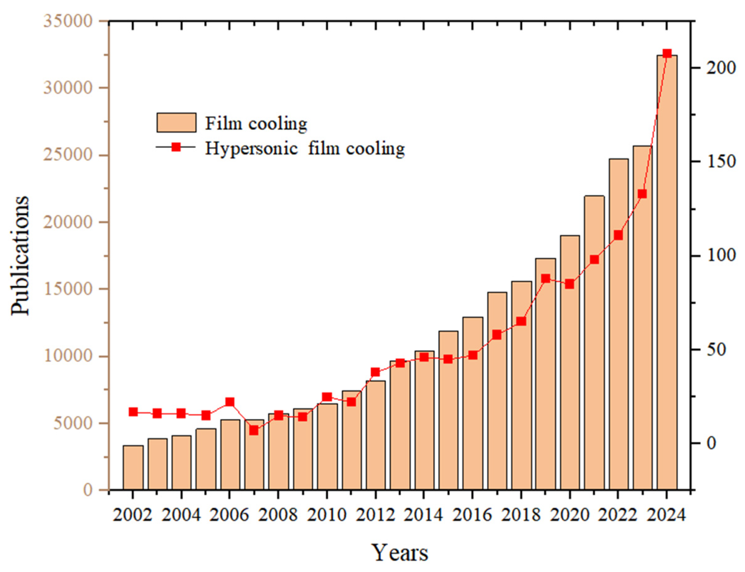
Figure 11: The number of journal papers on gas film cooling.
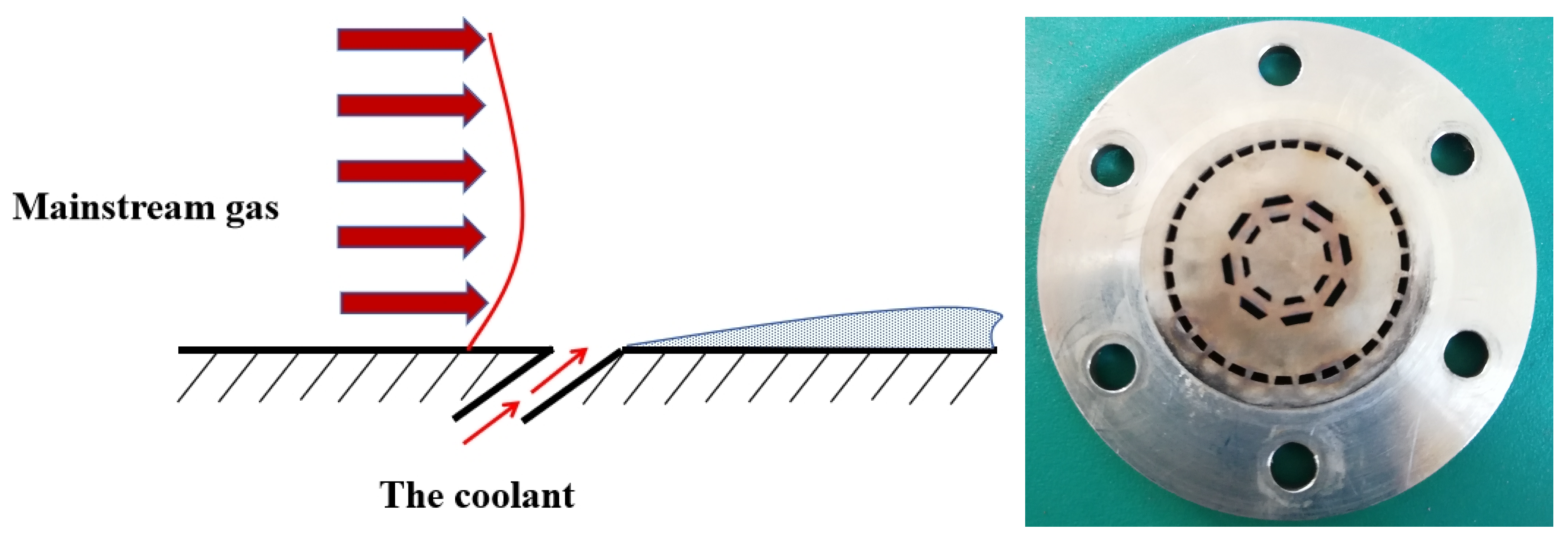
Figure 12: Principle of gas film cooling and picture.
Table 1: Factors influencing gas film cooling.
| Main Parameter | Influencing Factors | Reference |
|---|---|---|
| The process structure of the holes | the shape of the holes, the spray angle, the hole length, and the hole diameter | [74,75,76] |
| Jet and mainstream parameters | mainstream velocity, blowing ratio, ratio of jet to mainstream density, momentum ratio, jet pressure loss, pressure gradient, mainstream turbulence intensity, mainstream boundary layer thickness, shock wave | [77,78] |
| Hole arrangement process spacing | row spacing, row number, and arrangement method | [79,80,81] |
| Other parameters | cooling medium, wall shape, surface curvature, and surface roughness | [82,83] |
In the study of gas film cooling, a key parameter commonly employed to characterize the behavior of film cooling is the blowing ratio M, defined as
In the formula,
The cooling effect of the gas film can be characterized by that of the heat insulation gas film. The cooling efficiency of the gas film is defined as a dimensionless ratio of temperature differences.
In the formula,
When defining the cooling efficiency of supersonic gaseous films, the recovery temperature is typically employed and is defined as follows:
In the formula,
In the formula,
From the above formula, it can be observed that the primary factors influencing the cooling efficiency of supersonic gas films are molecular weight, specific heat capacity, viscosity, and speed of sound. Gulhan et al. [87] employed air and helium as coolants and compared their film cooling performance under identical flow conditions. The experimental results indicate that lighter gases exhibit superior cooling effectiveness when used as coolants. This is attributed to the fact that, at the same mass flow rate, lighter gases yield a larger volumetric flow rate, thereby forming a thicker and more effective protective gas film. When an incident shock wave interacts with the cooling gas film, the tangential injection of a coolant with a relatively lower molecular weight tends to induce more intense mixing between the mainstream flow and the coolant, accelerating the dissipation of the coolant. However, Peng et al. [88] and Ni et al. [89], in their investigations on the cooling performance of shock wave interactions with tangential slit gas films, found that although shock wave incidence promotes faster dissipation of gases with lower molecular weights, helium—despite its low molecular weight—achieves the highest cooling effectiveness. This superior performance is primarily due to helium’s higher specific heat capacity. Furthermore, the influence of viscosity on gas film cooling efficiency cannot be overlooked. Keller et al. [90] demonstrated that viscosity and thermal conductivity are linked through the Prandtl number. Assuming constant Prandtl number and heat capacity, a osity leads to a decrease in thermal conductivity. Since low viscosity is associated with low thermal conductivity, coolants with lower viscosity offer enhanced advantages in terms of thermal protection.
According to the jet angle between the mainstream and the coolant, gas film cooling technology can be classified into tangential gas film cooling, cross-jet gas film cooling, and counter-jet gas film cooling [91,92]. Tangential slot film cooling is the most fundamental and widely used configuration [93]. Its principle involves injecting coolant through holes or slots at a shallow angle of 20° to 45° relative to the wall surface, such that the coolant flow direction is nearly aligned with that of the high-temperature mainstream [94,95], as showed in Fig. 13. The coolant then spreads along the wall, forming a protective low-temperature gas film. By directly covering the surface and reducing the temperature gradient in the near-wall region, this film effectively isolates the wall from the hot gas and suppresses convective heat transfer. However, the primary challenge arises from the velocity shear between the coolant jet and the mainstream, which induces a pair of counter-rotating vortices (CVP). These vortices act similarly to a winch mechanism, entraining high-temperature fluid from the outer flow toward the wall while simultaneously lifting the cooler fluid away from the surface. This process leads to the formation of “hot spots” in the regions between adjacent cooling holes, resulting in a significant deterioration of cooling effectiveness downstream. Consequently, despite its simple structure and acceptable performance at low blowing ratios, the detrimental impact of CVPs limits the overall cooling efficiency. As such, tangential film cooling is predominantly employed in gas turbine blades and other components subjected to relatively moderate heat loads [96].
Unlike tangential gas film cooling, cross-jet gas film cooling typically involves injecting the coolant into the mainstream at a large angle or perpendicularly. This configuration generates a strong kidney-shaped flow vortex, significantly enhancing the lateral diffusion of the cooling gas along the wall surface. As a result, the coverage width of a single hole is substantially increased, and the downstream distribution becomes more uniform. Furthermore, the induced vortex structure effectively “pins” the coolant close to the wall, improving resistance to flow separation and enhancing stability under adverse pressure gradients. The primary limitation of this approach lies in the intense three-dimensional vortex system, which promotes premature mixing between the coolant and the mainstream in the vicinity of the injection orifice. This may lead to lower cooling effectiveness in the near-orifice region compared to tangential jet configurations. Additionally, the complex vortex dynamics pose a risk of entraining high-temperature mainstream gas toward the wall, potentially resulting in localized hot spots.
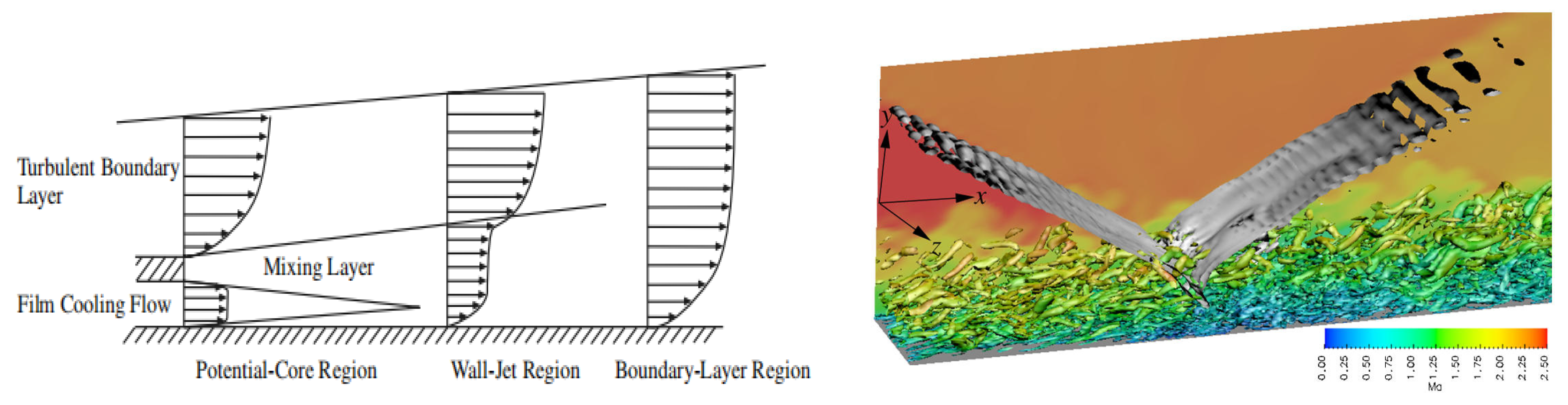
Figure 13: The principle of tangential gas film cooling and the flow structure of the cross-jet gas film cooling.
Zhou et al. [97] investigated the flow and heat transfer characteristics of a impingement/effusion composite cooling structure through numerical simulations, revealing that reducing hole spacing and increasing the blowing ratio can significantly enhance wall cooling performance. Rozati et al. [98] employed large eddy simulation to analyze the flow structures and adiabatic effectiveness of film cooling at the leading edge of a cylinder under various blowing ratios, and concluded that although an increased blowing ratio enhances jet-mainstream mixing, it simultaneously reduces cooling efficiency. Saumweber et al. [99] experimentally examined the impact of freestream turbulence on the cooling performance of film cooling with different hole geometries. The results indicated that the cooling effectiveness of cylindrical holes deteriorates under high-turbulence conditions, whereas fan-shaped holes are more vulnerable to adverse effects from turbulence, particularly at elevated blowing ratios. Lee et al. [100] conducted a numerical study on the mixing characteristics of dual transverse injection in scramjet engines, demonstrating that the rear injection is strongly influenced by the blockage effect induced by the front jet, and that an optimal injection spacing exists to maximize both mixing efficiency and penetration depth. All of the aforemtioned literature has highlighted the critical influence of flow parameters and structural optimization on cooling and mixing performance, as showed in Fig. 14.
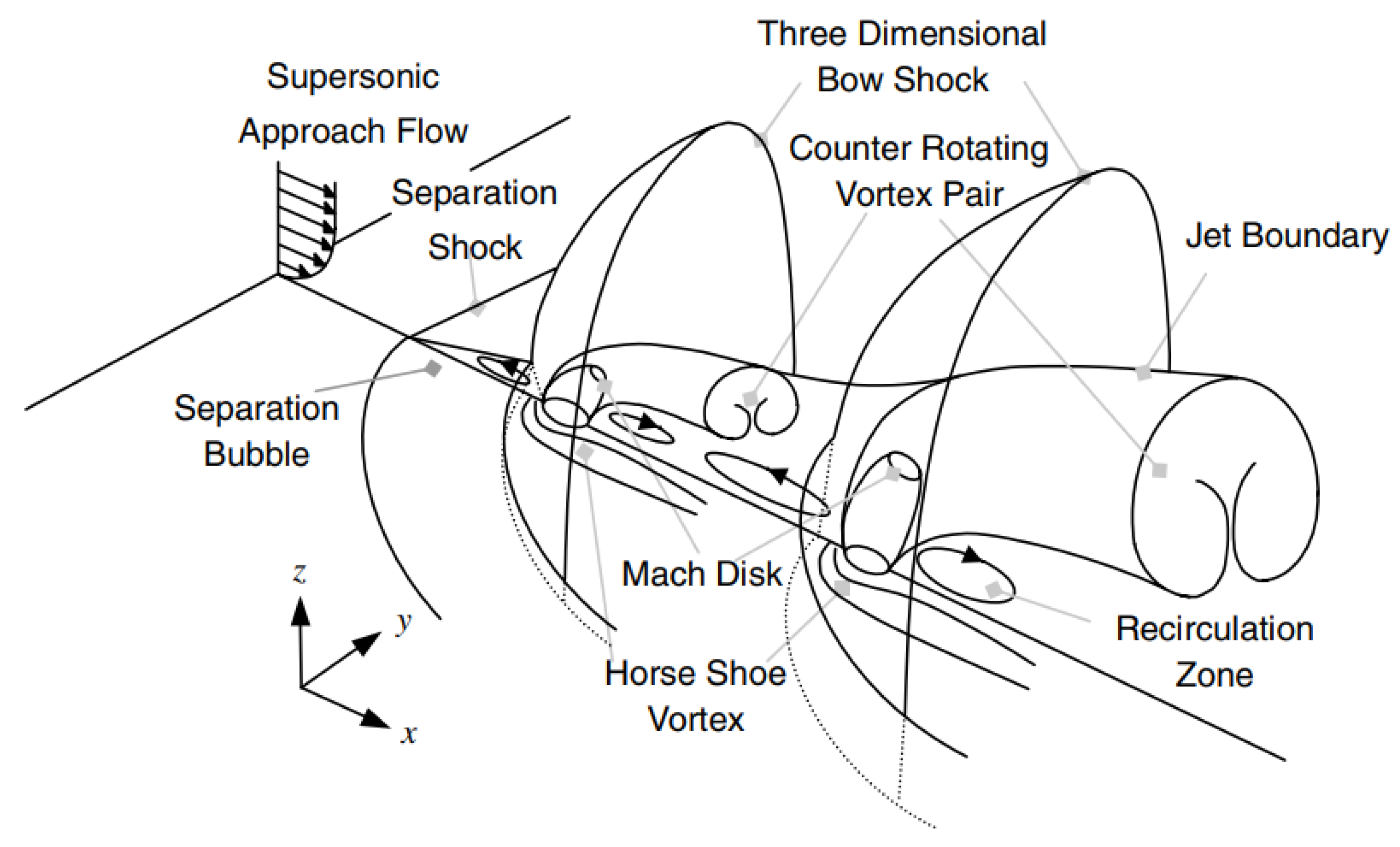
Figure 14: Schematic view of mean flowfield of dual transverse injection.
Opposing jet technology represents a revolutionary and cutting-edge concept, wherein coolant is injected directly against the direction of the mainstream flow. The underlying mechanism transcends simple surface “coverage” and instead relies on the formation of an aerodynamic barrier: a high-speed reverse jet generates a stable, enveloping, and protruding aerodynamic structure upstream of the injection point. This structure induces significant deflection of the high-temperature mainstream, effectively preventing it from reaching the actual wall surface [101], as showed in Fig. 15. Intense mixing between the coolant and the mainstream occurs in the region far ahead of the wall, resulting in the formation of a large low-temperature coolant mass that substantially reduces the temperature of the fluid reattaching downstream. This cooling mechanism achieves exceptionally high efficiency—far surpassing conventional methods—and demonstrates particular effectiveness in protecting the most critical upstream regions. However, this comes at the cost of considerable aerodynamic drag and remarkably high coolant consumption, rendering it a frontier technology still under active investigation for addressing extreme thermal environments.
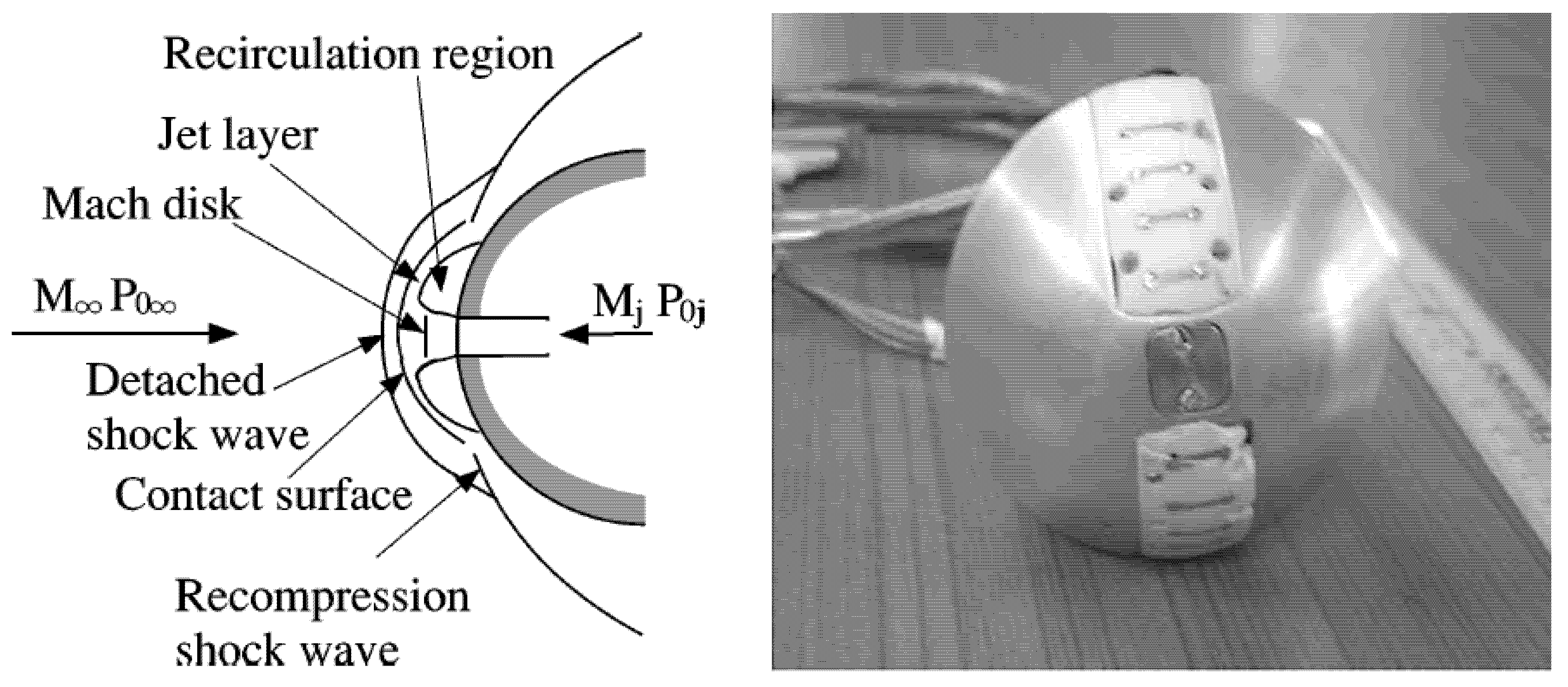
Figure 15: Opposing jet principle and physical diagram.
In 1952, Love introduced the opposing jet concept into the supersonic flight regime and demonstrated that the opposing jet exhibits superior performance in supersonic flow compared to its performance in low-speed flight conditions [102]. Subsequently, numerous scholars have conducted extensive investigations into its underlying working mechanisms [103]. A review of the existing literature reveals that current research on opposing jet technology primarily focuses on the following aspects:
2.2.1 Numerical Simulation and Experimental Investigation of Opposing Jet Flow
In 1976, Schiff conducted the first numerical simulation study on opposing jets, primarily aiming to assess the simulation capabilities and investigate the physical characteristics of the numerically generated flow field [104]. Sun et al. [105] carried out numerical simulations on the integration of aerospike with opposing jets under hypersonic freestream conditions, as well as on the combination of forward-facing cavities and opposing jets, providing a comprehensive review of the current research status on opposing jets, with particular emphasis on advancements in numerical simulation studies [106]. Gerdroodbary et al. [107] investigated the drag reduction and thermal protection performance of a porous opposing jet using numerical simulation methods, and concluded that it outperforms the single jet. Huang et al. [108,109] systematically studied, through numerical simulations, the influence of opposing jet orifice configurations on drag reductionnd thermal protection efficiency. They analyzed the effects of key parameters such as total jet pressure ratio, angle of attack, and freestream Mach number on the aerodynamic and thermal performance.
In 2021, Ji et al. [110] conducted numerical simulations on porous opposing jets and observed that the jet displaced the bow shock wave at the leading edge of the forebody outward, resulting in the formation of multiple Mach disks and internal recirculation zones. These findings confirmed the significant effectiveness of porous jets in drag reduction and thermal protection, thereby promoting advancements in the optimization of jet configurations. Gao et al. [111] through detailed analysis of the flowfield structure, revealed that the interaction between the counter-flow jet and the incoming airflow generates a Mach disk to achieve pressure equilibrium. They further proposed integrating opposing jets with other techniques such as aerospike and forward-facing cavities, offering new insights for the technological application. Deng et al. [112,113] performed numerical simulations on a lift-body vehicle under opposing jet conditions at an incoming flow Mach number of 8, focusing on the drag reduction performance of the long penetration mode (LPM) and its associated periodic oscillation characteristics. Shang et al. [114] experimentally obtained numerical shadowgraphs for both the long and short penetration modes (LPM and SPM), as shown in Fig. 16, and identified shock bifurcation phenomena arising from the interaction between the counter-flow jet and the shock wave. Fig. 17 illustrates the schematic diagrams depicting the flow field structures associated with the SPM and LPM modes [115,116].
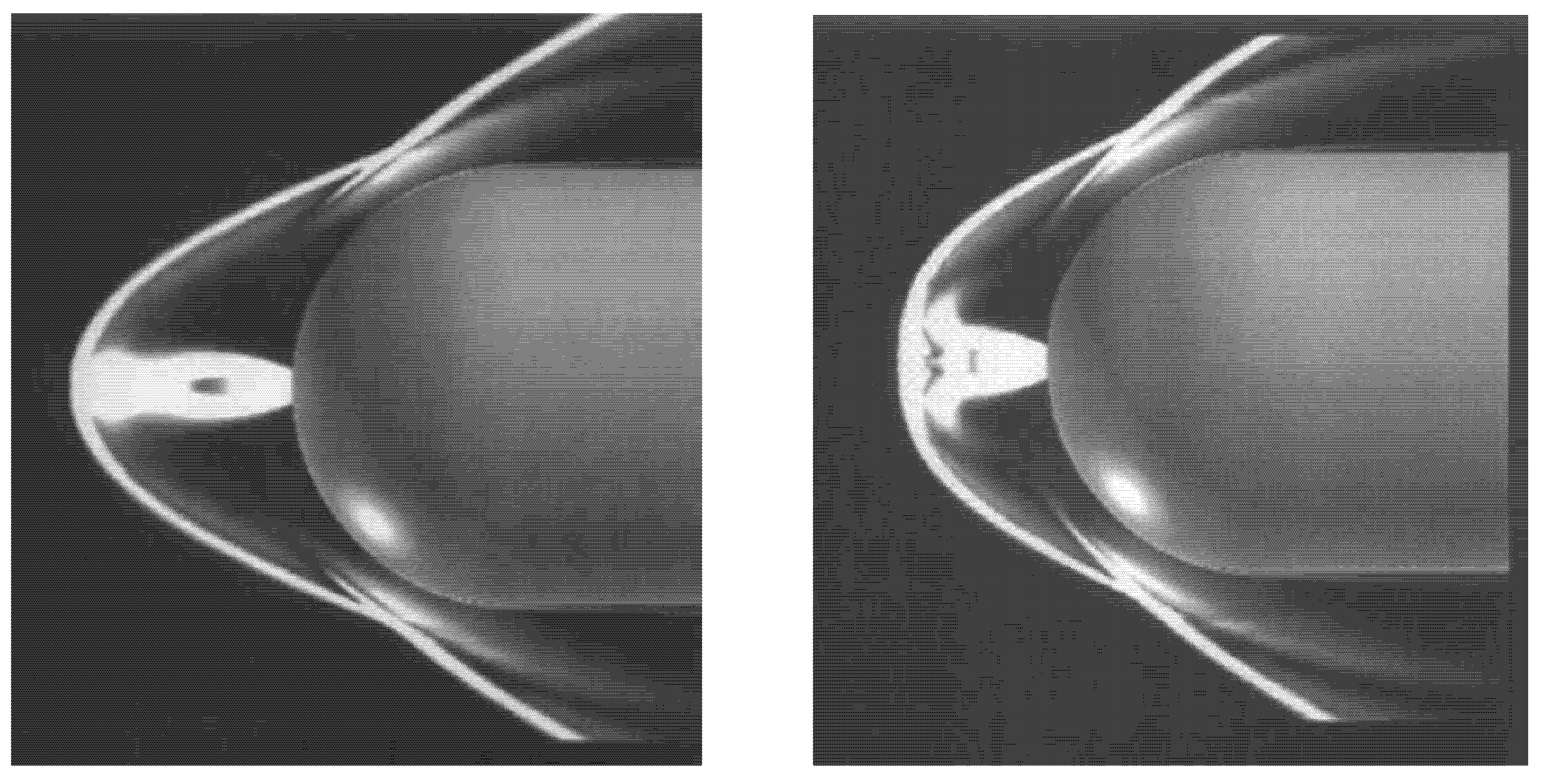
Figure 16: Comparison of shadow plots between the two flow modes, LPM and SPM.
Hayashi et al. [117,118] investigated the opposing jet heat protection scheme for a spherical nose configuration with a diameter of 50 mm under an incoming flow condition of Mach 3.98, using nitrogen as the jet working medium. Finely conducted wind tunnel experiments on spherical nose models featuring a opposing jet outlet at Mach 1 under supersonic freestream conditions, measuring the surface pressure distributions on the nose models at various total opposing jet pressure ratios [119]. Venukumar et al. [120,121] studied the drag reduction performance of a spherically blunted cone with a cone angle of 120 degrees in an 8-Mach high-enthalpy flow using the HST2 wind tunnel. Their results indicated that, at a pressure ratio (PR) of 75, the drag coefficient was reduced by approximately 45%, as illustrated in Fig. 18.
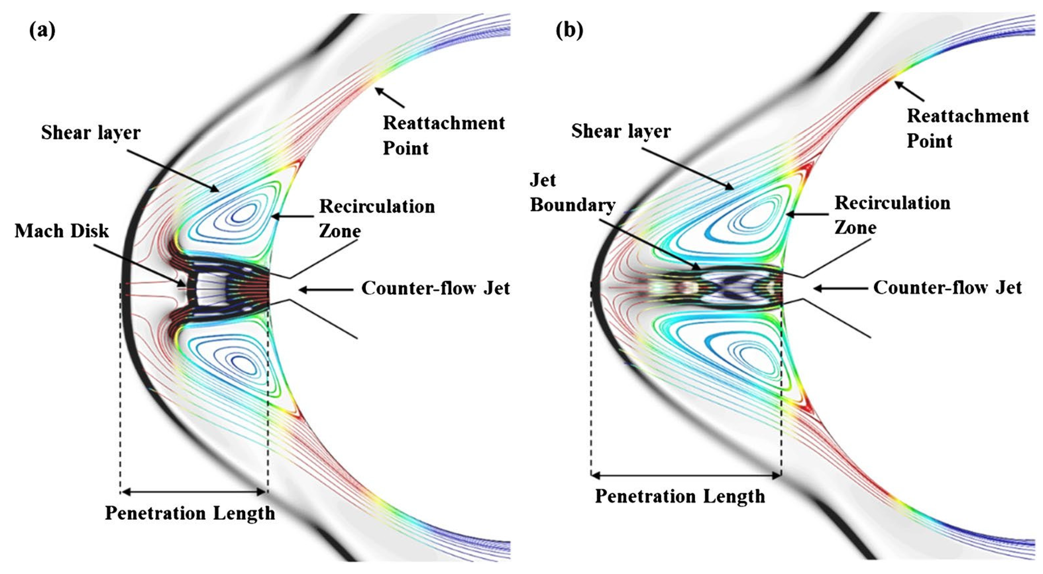
Figure 17: Schematic illustration of the flow field structure: (a) SPM; (b) LPM, based on reverse jet combination technology.
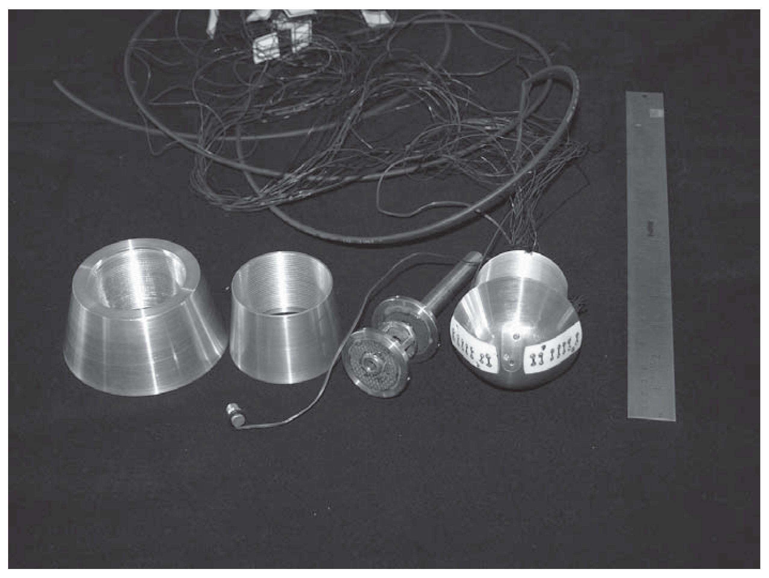
Figure 18: Photograph of a blunt cone model.
2.2.2 Research on Combined Flow Control Technology with Opposing Jet
Opposing jet combined flow control technology, as a key approach for drag reduction and thermal protection in hypersonic vehicles, exhibits significant advantages in mitigating aerodynamic drag and alleviating aerodynamic heating through the synergistic integration of various flow control elements. Several commonly adopted combination strategies currently include: the opposing jet combined with a forward-facing cavity, the opposing jet integrated with aerospike, the opposing jet coupled with aerodisk, and the opposing jet combined with energy deposition [122,123,124].
The combination of a opposing jet and a forward-facing cavity has been demonstrated to be an effective integrated thermal protection solution. Fig. 19 illustrates a missile experimental model featuring a forward-facing cavity structure [125]. Huang et al. [126,127] systematically introduced the novel concept of integrating a forward-facing cavity with opposing jet technology. By employing a multi-objective design optimization approach, they identified the optimal structural parameters for this combined configuration. Research indicates that this hybrid scheme utilizes the reverse jet flow to push the bow shock wave away from the vehicle surface, while simultaneously generating a recirculation zone within the concave cavity, thereby further reducing the wall heat flux density. The integrated structure achieves a synergistic effect between two protective mechanisms: the reverse jet modifies the shock wave structure, whereas the concave cavity promotes vortex formation, effectively shielding the wall surface from direct impingement by high-temperature external flows. Lu et al. [128,129,130] proposed a combined drag-reduction and thermal protection strategy incorporating a forward-facing cavity and counter-flow jet, and conducted comprehensive optimization studies. They observed that when the cavity length is too small, the jet energy is excessively dissipated, whereas an excessively large cavity length may accelerate the flow at the nozzle exit. The performance of this combined configuration significantly surpasses that of either individual technique alone.
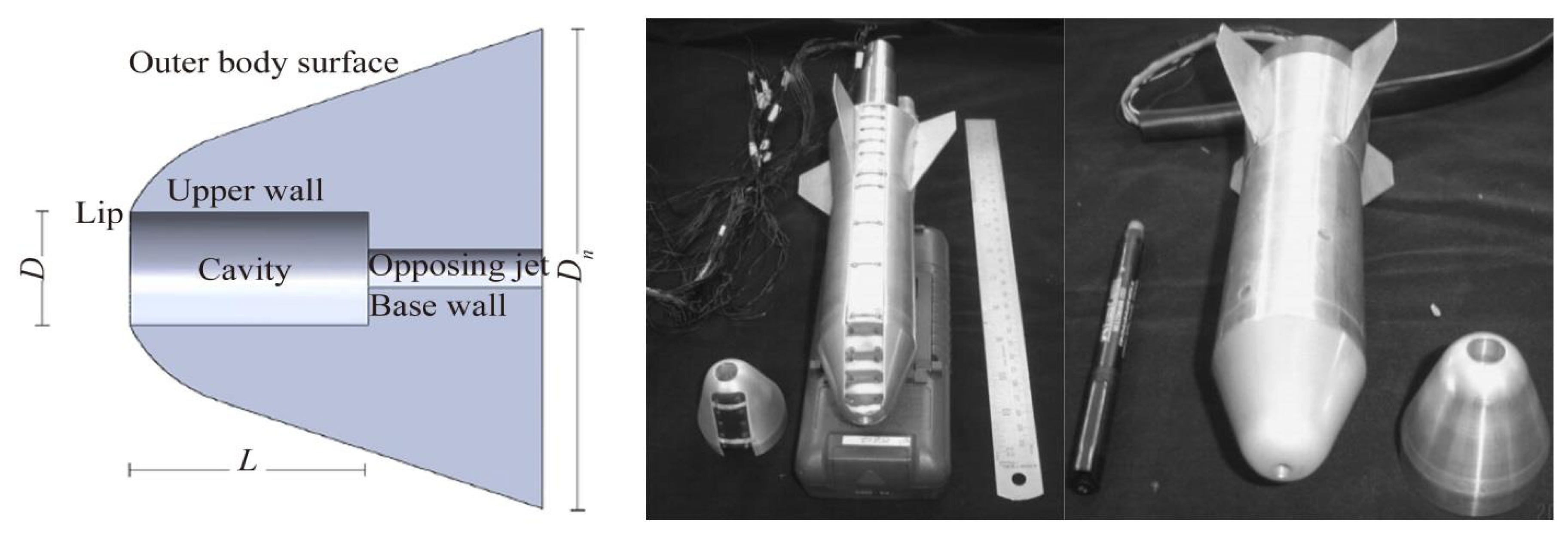
Figure 19: Experimental missile model with forward-facing cavity structure.
The aerospike and the aerodisk, as conventional drag reduction devices, exhibit a more comprehensive performance enhancement when integrated with a opposing jet. Jiang et al. [131,132] demonstrated that introducing lateral jet flow at the tip of the aerospike can effectively reduce heat flux at both the end of the aerospike and the shoulder region of the blunt body. Liu et al. [133] further indicated that the angle-of-attack performance of this combined configuration surpasses that of a simple reverse jet alone, while also achieving ablation-free operation of the drag reduction rod. G. Aswin et al. [134] developed an integrated protective approach combining aerospikes with lateral jets, conducting both numerical simulations and experimental investigations on their flow characteristics using flight parameters from actual missile models. The results reveal that, compared to the baseline aerospike, the incorporation of lateral jets alters the external flow field and contributes to additional reductions in the vehicle’s drag coefficient. Xu performed a numerical study on the drag reduction and thermal protection performance of combined configurations involving aerospikes/aerodisk and opposing jet flows. The findings show that, by appropriately optimizing the geometry of the aerospikes/aerodisk and the parameters of the double jet system, a drag reduction efficiency of 57.1% can be achieved, accompanied by a thermal protection efficiency reaching 100.4% [135]. Fig. 20 presents the Mach number contour maps of the downstream flow field for various aerospikes configurations [136].
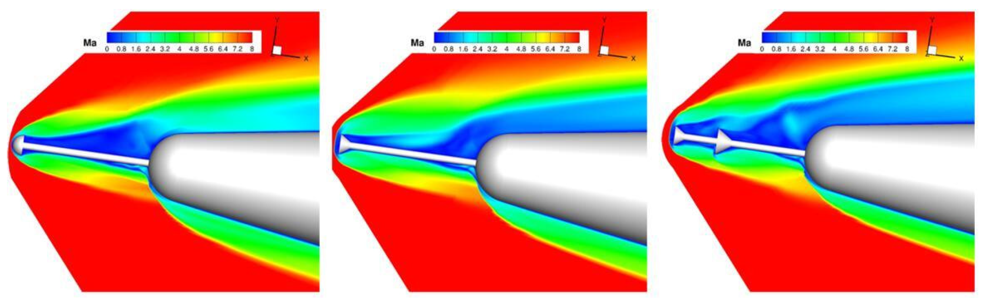
Figure 20: Mach number contour maps of the downstream flow field for various aerospikes configurations.
In addition to the two primary combination schemes mentioned above, scholars have recently explored various novel integration approaches. Huang [137,138] investigated the effects and fundamental mechanisms of combined cooling using transpiration cooling and opposing jet in scramjet engines. The results indicate that the synergistic application of transpiration cooling and opposing jet significantly influences shock wave distribution. When coupled with a non-uniform injection strategy, this method can substantially enhance cooling efficiency. Rong [139,140] integrated platelet transpiration with opposing jet flow, achieving a more pronounced thermal protection effect. Compared to cases without opposing jet flow, the maximum temperature was reduced by approximately 200 K, thereby offering a promising approach for improving both thermal management and drag reduction in high-speed aircraft.
From the perspective of engineering application, the complexity and reliability of various integration schemes constitute critical criteria for selection. A simple opposing jet system features a relatively straightforward structure; however, its effectiveness is significantly limited under conditions of low total pressure ratio. Although combined configurations offer superior performance, they entail increased system complexity and added weight. Consequently, in practical engineering applications, trade-offs must be carefully evaluated and implemented according to the specific mission requirements and operational constraints of the aircraft.
2.2.3 Research on the Opposing Jet Orifice Structure
The performance of opposing jet technology is predominantly influenced by the structural design of the jet orifices, including their geometry, dimensions, spatial distribution, and arrangement. An optimized nozzle configuration can effectively enhance the interaction between the jet flow and the freestream, thereby significantly improving the aircraft thermal protection and drag reduction capabilities.
The shape of the nozzle hole is one of the key factors influencing the performance of opposing jet flows. Shang et al. [141] systematically investigated the gas film cooling effectiveness of four distinct hole geometries—cylindrical, contraction, expansion, and contraction-expansion holes—under hypersonic conditions using computational fluid dynamics (CFD) simulations. The results indicate that, under low-mass-flow supply conditions, contraction holes and cylindrical holes are prone to exhibit long penetration modes (LPM), whereas expansion holes and contraction-expansion holes do not display this behavior. As the jet mass flow rate increases, all hole types transition from the long penetration mode to the short penetration mode (SPM). Beyond this point, further increasing the gas film flow rate yields only marginal improvements in cooling performance. Considering the overall evolution of the flow field, the expansion hole demonstrates the most stable and reliable performance in counter-flow jet film cooling at the nose section of hypersonic vehicles. In porous opposing jet systems, the optimized design of hole size and hole spacing significantly influences the thermal reduction efficiency. Zhou conducted a study on the application of a porous opposing jet to the sharp leading edge of an X-51A-like vehicle, revealing that, with an appropriate hole configuration, the porous structure can significantly modify the leading-edge flow field and effectively mitigate aerodamic heating at the leading edge [142].
In addition to conventional nozzle configurations, specially shaped nozzles have also exhibited distinct advantages in the study of opposing jet flows. Li et al. [143,144] conducted an in-depth investigation into the effects of opposing jet hole geometry and inflow conditions on the drag reduction and thermal protection performance of the opposing jet system. They found that, in terms of minimizing drag on the surface of a blunt-body nose, the five-pointed star nozzle, as illustrated in the Fig. 21, achieves the most favorable outcome. However, when both drag reduction and thermal protection are considered comprehensively, the square nozzle demonstrates the optimal overall performance.
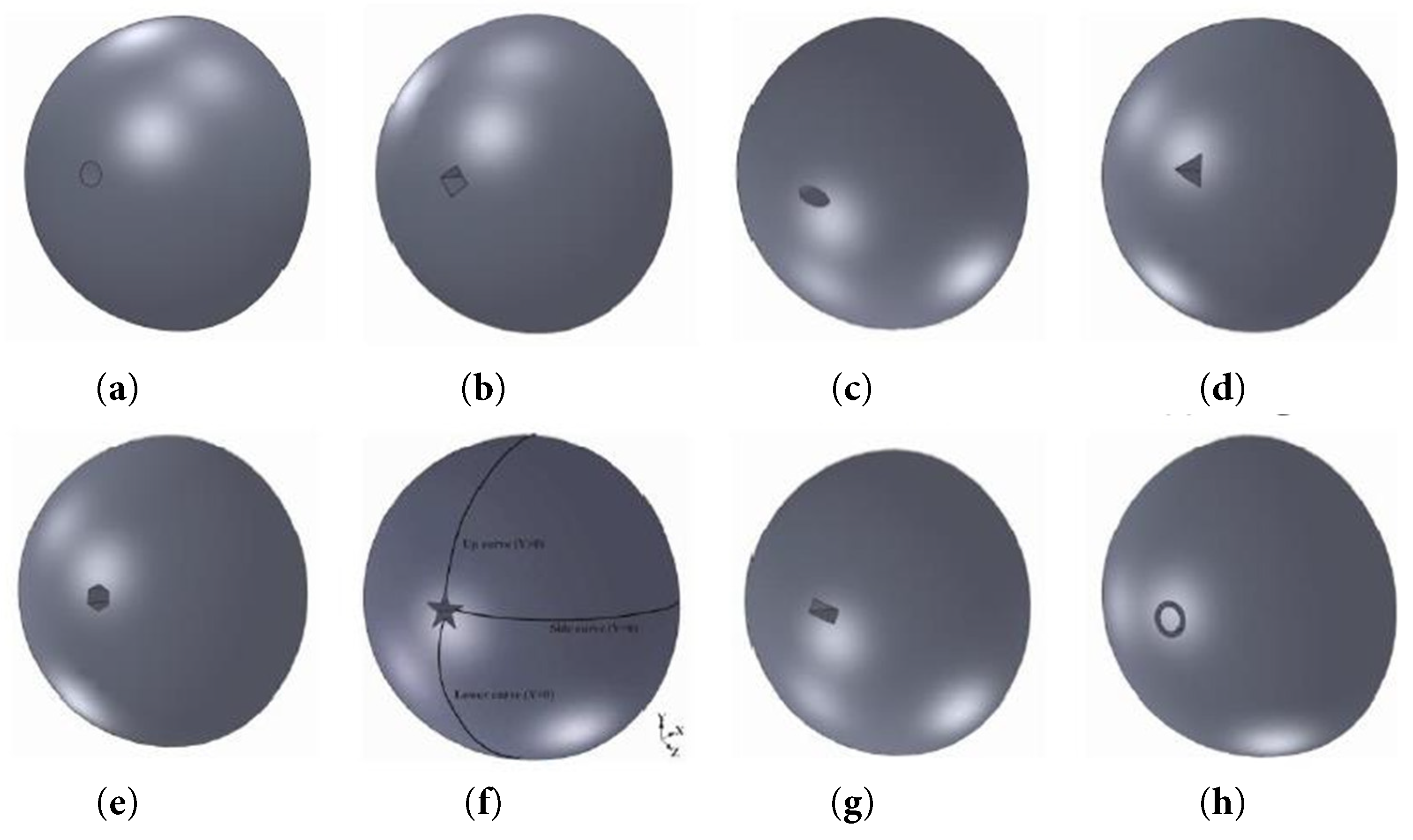
Figure 21: Various jet nozzle configurations; (a) circle; (b) square; (c) oval; (d) triangle; (e) hexagon; (f) Five-pointed star. (g) Rectangle; (h) ring.
Extensive investigations have been conducted on the effects of porous opposing jets. Jagadeesh et al. [145] carried out a wind tunnel experiment with an incoming flow Mach number of 5.9 to evaluate the performance of a porous opposing jet configuration. Their results demonstrated that the porous opposing jet exhibits superior cooling effectiveness. Huang et al. [108,109] performed numerical simulations on porous jets applied to hypersonic vehicles, systematically examining the influence of key parameters—such as total jet pressure ratio, angle of attack, and freestream Mach number—on drag reduction performance. They also conducted a preliminary analysis of the underlying mechanisms responsible for drag reduction and thermal protection in blunt-body hypersonic vehicles equipped with porous jets. Furthermore, Rong [146] and Shen [147,148,149], among others, proposed a novel porous jet device tt integrates opposing jets with cooling pores, and conducted comprehensive numerical studies to assess its performance.
Research on the structural design of opposing jet nozzle orifices indicates that the geometry, dimensions, spatial distribution, and specialized configurations of the orifices exert a decisive influence on jet performance. Expanded orifices demonstrate stable operation under hypersonic conditions. An optimal ratio of orifice diameter to spacing can significantly improve thermal mitigation effectiveness. Multi-orifice distribution strategies, such as double-row internal jet configurations, not only ensure high performance but also enhance engineering practicality. Future research should focus more intensively on multi-parameter collaborative optimization and, in conjunction with specific application requirements, advance the development of more efficient nozzle structural designs.
2.3 Transpiration Cooling Technology
Transpiration cooling technology represents one of the most efficient active thermal management strategies currently known [150,151,152,153,154]. As a promising approach for advanced thermal protection systems, it holds significant potential for practical applications and has therefore garnered considerable research interest. Although this concept was introduced at an early stage, its engineering implementations to date are primarily confined to the cooling of components such as liquid rocket engine combustion chambers. Its extension to other aerospace components—such as the nose cone and leading edges—remains largely in the exploratory phase with respect to underlying mechanisms. The complex interaction between the coolant and the external flow fieldequires further in-depth investigation.
Transpiration cooling refers to a process in which the cooling medium permeates uniformly and in trace amounts from the heated surface, forming a continuous gaseous cooling film that covers the outer surface of the wall, thereby achieving effective thermal protection. The underlying principle is illustrated in Fig. 22. The thermal protection mechanism of this technology primarily involves two aspects: First, the injection of the cooling medium elevates the boundary layer, effectively isolating the high-temperature gas from the wall surface. Simultaneously, the thickened boundary layer increases convective heat transfer resistance, thereby attenuating the direct impact of high-temperature heat flux on the wall—this constitutes the insulation effect. Second, as the cooling medium passes through the porous structure of the wall, it absorbs heat and carries it away, reducing the overall structural temperature; this is known as the endothermic effect [155,156].
Overall, current research on transpiration cooling primarily centers on porous materials, phase transformation mechanisms, and conventional microporous structures. Based on the differences in base materials utilized during the transpiration cooling process, transpiration cooling materials can be categorized into the following types: sintered metal porous materials, platelet materials, ceramic matrix composites, and self-sweating materials, as illustrated in Fig. 23.
In the early stages of research on transpiration cooling technology, sintered metal porous materials were predominantly employed as the cooling medium. Ding systematically outlined the fabrication process for porous materials based on the sintering of metal particles, covering critical steps such as powder preparation, compaction and shaping, and high-temperature sintering [157]. These materials contain a large number of fine internal channels that enable the flow of coolant, thereby achieving efficient heat dissipation. Xiong et al. [158] investigated transpiration cooling using sintered metal porous materials in the support plate structure of a scramjet engine combustion chamber. Their study revealed that once the coolant mass flow rate exceeded a certain threshold, the temperature of the hot wall could be maintained within a safe operational range. Xu et al. [159] experimentally compared the cooling performance of sintered steel wire meshes with varying porosities. Furthermore, Vikulin et al. [160] explored the application of sintered stainless steel fiber materials inranspiration cooling, demonstrating that this approach can significantly enhance the thermal resistance and high-temperature capability of gas turbine blades.
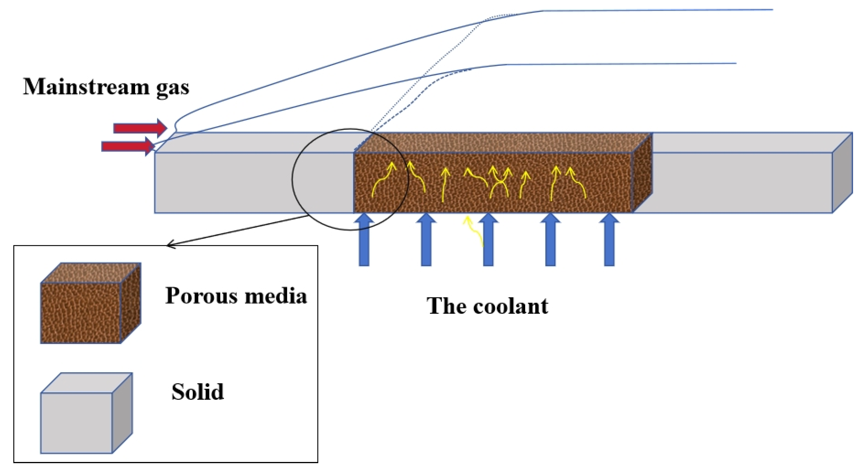
Figure 22: Principle of transpiration cooling.
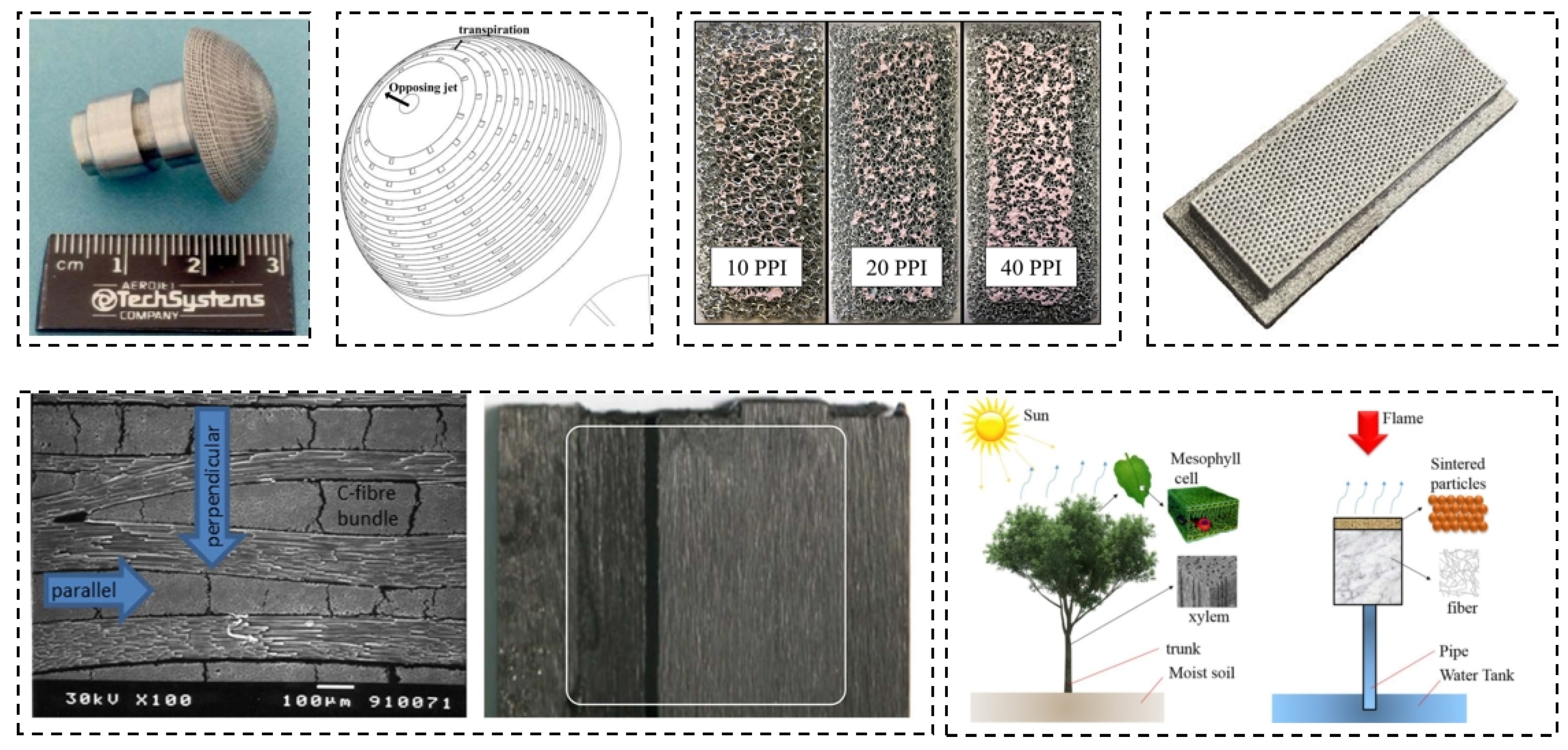
Figure 23: Transpiration cooling materials.
In addition to traditional metallic porous materials, ceramic porous materials have increasingly been applied in the field of transpiration cooling in recent years. Sun et al. [161] conducted an experimental investigation on transpiration-cooled porous plates fabricated from porous ceramics and sintered stainless steel, using hydrogen as the coolant. The results demonstrated that transpiration cooling can effectively reduce convective heat flux between the wall surface and the surrounding gas. Zhang et al. [162,163] developed a C/SiC ceramic matrix composite with several advantageous characteristics, including low density, uniform pore size distribution, and high thermal stability. König et al. [164] experimentally determined the permeability and effluent flow distribution characteristics of carbon/carbon composites, as illustrated in Fig. 24, and further analyzed the formation mechanism of the cooling gas film within high-temperature flow channels by integrating numerical simulations.
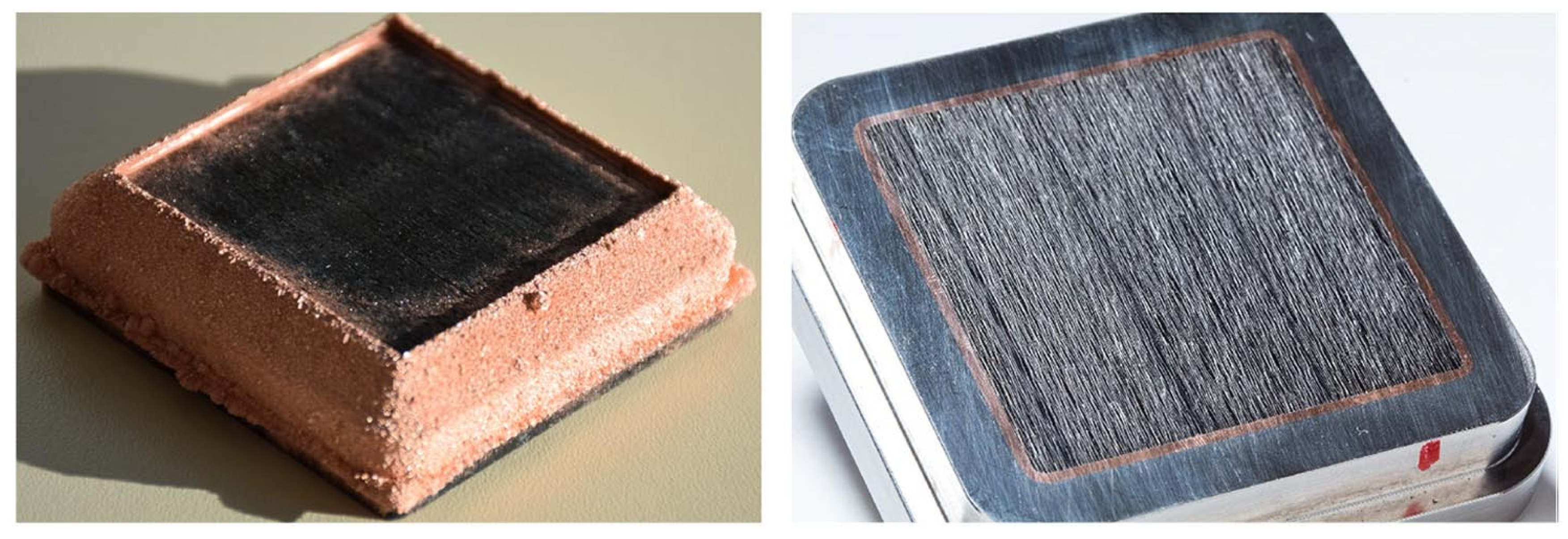
Figure 24: Image of the C/C microstructure.
The concept of platelet transpiration cooling technology originates from the idea proposed by M. Zucrow in 1948 [165]. In 1964, Aerojet further advanced this concept by proposing a platelet transpiration cooling scheme specifically designed for fabricating coolant channels on the surface of rocket thrust chambers [166], marking the first practical engineering application of this configuration. In recent years, numerous researchers have integrated additive manufacturing techniques with innovative platelet structures to investigate the comprehensive cooling performance of supersonic rocket thrust chambers under extreme high-temperature and high-pressure conditions through both numerical simulations and experimental studies. Shen [147,148,149,167,168] combined platelet transpiration with opposing jet and demonstrated that incorporating transpiration cooling significantly improves heat transfer characteristics at the outflow and wall surfaces, thereby enhancing thermal protection. He et al. [169] designed and fabricated a novel platelet transpiration cooling thrust chamber structure, evaluating its overall cooling performance through a combination of numerical simulation and experimental validation, as illustrated in Fig. 25. Zhang et al. [170] investigated the underlying mechanisms of porous transpiration cooling. By focusing on sintered metal granular materials, he developed single-phase and phase-change mathematical models for transpiration cooling and systematically analyzed the heat transfer behavior of the coolant within the porous structure.
Phase change transpiration cooling has emerged as a prominent research focus in recent years due to its high cooling efficiency. This approach typically employs liquid media such as water or alcohol [171], leveraging the latent heat associated with phase transition to achieve effective thermal protection. The underlying process involves complex two-phase flow and heat transfer phenomena within porous media. Commonly used modeling approaches include the separated phase model (SFM) and the two-phase mixture model (TPM). Taking water as an example, the structure of the porous medium significantly influences two-phase flow behavior, often leading to issues such as vapor blockage, cooling delay, and temperature fluctuations, which collectively complicate precise control of the cooling performance. The coolant injection rate plays a critical role in determining both the location and extent of phase change. Differences in flow resistance between the liquid and vapor phases can result in vapor blockage, subsequently increasing injection pressure and causing localized overheating. Furthermore, particle diameter exerts a dual influence on cooling effectiveness: reducing particle size enhances heat transfer by increasing surface area, but it also amplifies the disparity in two-phase flow resistance and intensifies vapor phase resistance [172,173,174,175].
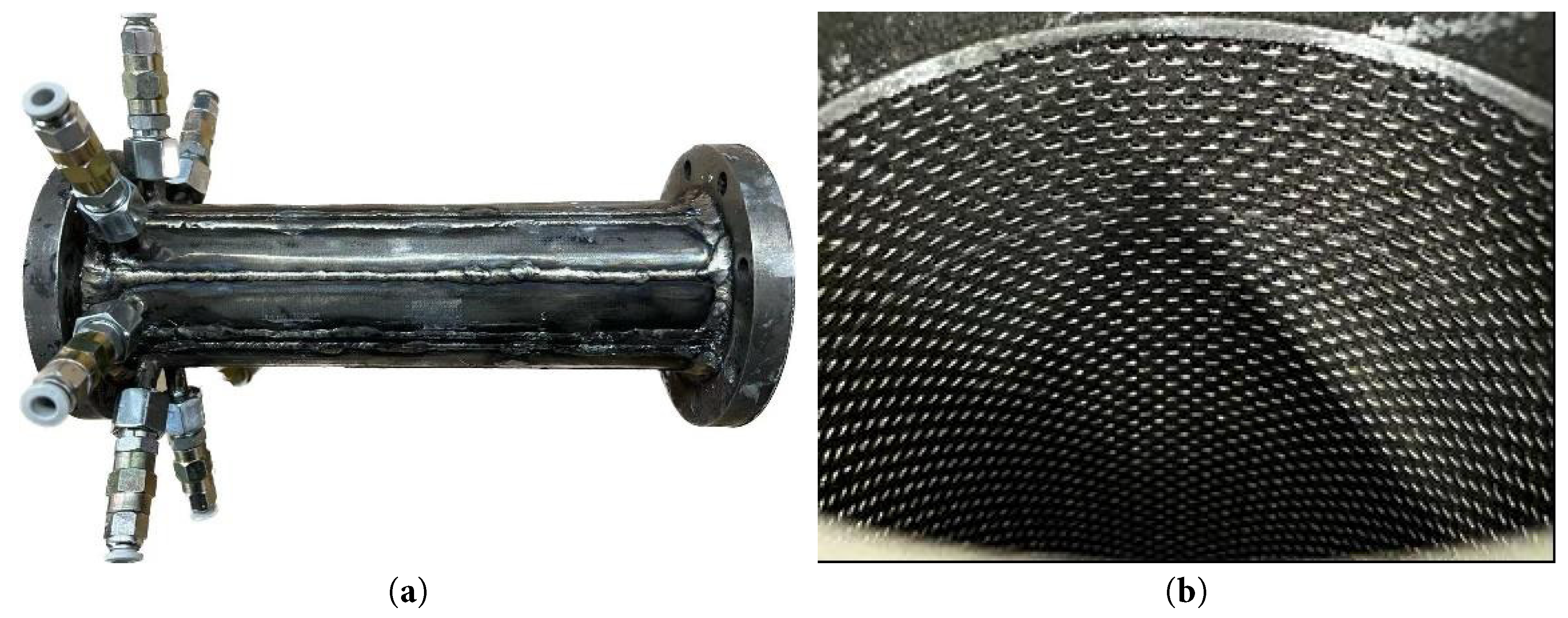
Figure 25: Platelet transpiration cooling thrust chamber.
In terms of relevant numerical and experimental studies, Forrest et al. [176] investigated the transpiration cooling performance of water and nitrogen on sintered ceramic porous nose tips in an arc wind tunnel under conditions of a total temperature of 3028 K and a Mach number of 5.45. The experimental results demonstrated that liquid water achieved significantly higher cooling efficiency compared to nitrogen, effectively reducing the nose tip temperature to below 300 K. Wang et al. [177] conducted experimental investigations on phase-change transpiration cooling using liquid water in a wind tunnel with a total temperature of 823 K and a Reynolds number of 16,000. Their findings revealed that liquid water exhibited the lowest flow resistance and superior cooling efficiency when permeating through porous walls. Ma et al. [178] examined the phase-change transpiration behavior of flat plates in a high-temperature wind tunnel, observing that the wall temperature distribution was non-uniform at low injection rates, whereas at high injection rates, phase change occurred at the surface, resulting in a more uniform temperature distribution. Reimer et al. [179,180] studied the liquid water phase-change transpiration cooling process of C/C nose tips in a supersonic wind tunnel and observed the formation of ice streaks during the experiment, as illustrated in Fig. 26.
In recent years, several innovative porous transpiration cooling structures have been developed, among which double-layer or multi-layer composite porous configurations with multiple functional characteristics stand out [181]. Luo et al. [182] investigated a double-layer transpiration cooling system applied at the leading edge of hypersonic vehicles, as illustrated in Fig. 27a, with particular emphasis on the influence of different coolants on cooling performance. Their findings indicate that, under the same mass flow rate, low-density coolants achieve superior cooling effectiveness due to their higher ejection velocity, and are capable of forming a recirculation zone at the leading edge, thereby significantly reducing the peak temperature. Conversely, at the same injection velocity, high-density coolants possess greater momentum, resulting in enhanced cooling performance. These results provide valuable insights for the design and optimization of active thermal protection systems in hypersonic vehicles. Ma et al. [183] conducted experimental studies on the transpiration cooling performance of sintered metal wire mesh structures incorporating various porosity combinations in both double-layer and triple-layer configurations, as illustrated in Fig. 27b. The results demonstrate that the average porosity of the porous medium has a significant effect on cooling efficiency—higher porosity leads to improved cooling performance. Analysis of flow pressure drop shows that the flow characteristics are well described by the modified Darcy equation. Jiang et al. [184,185,186] proposed a bionic self-priming phase-change transpiration cooling system that autonomously transports coolant via capillary forces and exhibits high sensitivity to mainstream variations, enabling effective constant-temperature control of the outer surface. However, this system has a maximum heat flux limit, the value of which depends on factors such as the thermophysical properties of the coolant, particle diameter, and permeability. Exceeding this threshold can result in system failure. Currently, this technology still faces challenges in meeting the high heat load cooling demands required for the surfaces of actual aircraft.
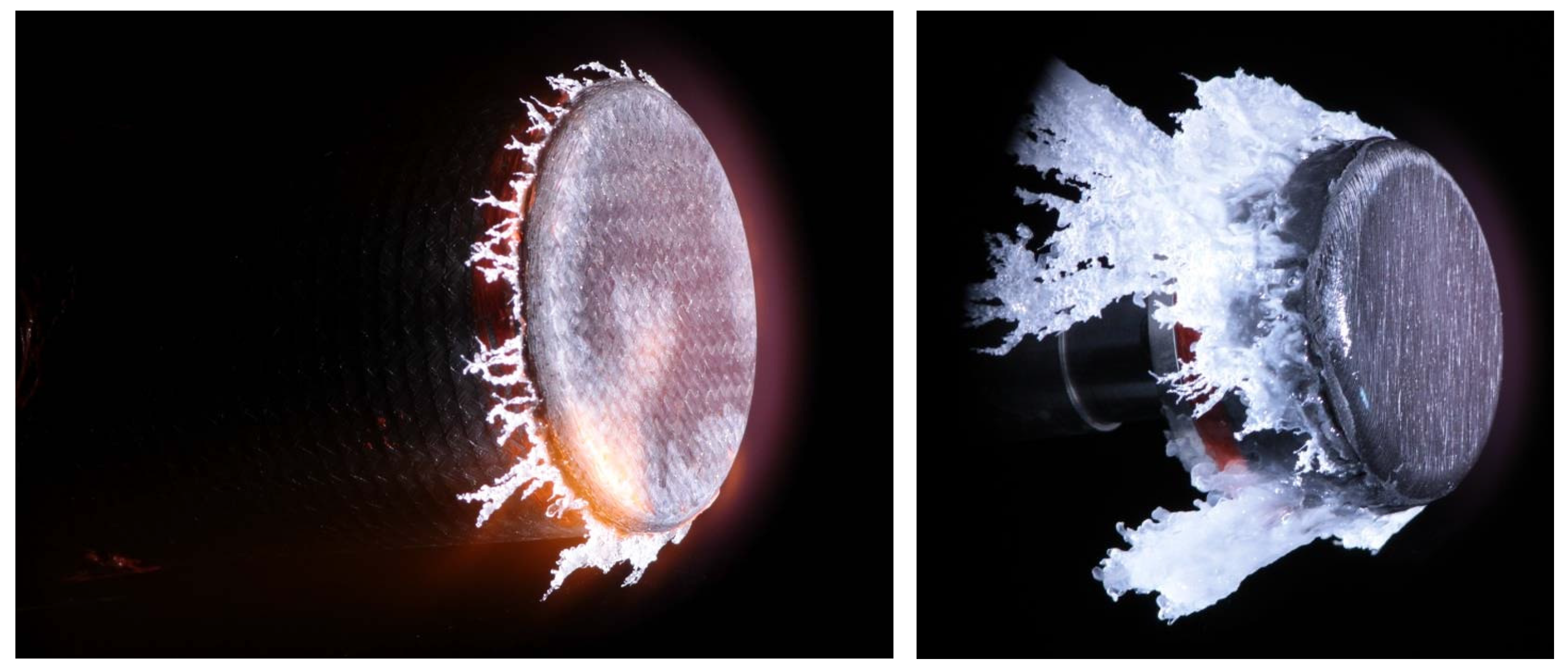
Figure 26: Ice streaks around the C/C sample.
In conclusion, within the hypersonic active cooling technology system, regenerative cooling—owing to its exceptionally high cooling efficiency and energy recovery capabilities—has emerged as the preferred solution for long-duration flight missions. Nevertheless, significant challenges arise from the intense thermo-mechanical-chemical coupling induced by its intricate flow channel network, the coking behavior of hydrocarbon fuels, and the potential deterioration of supercritical heat transfer performance. Gas film cooling enables rapid thermal response by injecting low-temperature gas through discrete orifices, offering flexibility in protecting localized hot spots. However, its cooling effectiveness diminishes sharply with increasing distance from the injection points, and the attendant thrust loss due to gas injection restricts its applicability for large-scale thermal protection. Transpiration cooling, which relies on the multi-level synergistic effects of permeation, phase change, and vapor film formation within porous media, theoretically achieves a cooling efficiency up to three times that of conventional gas film cooling. Nonetheless, engineering implementation remains hindered by challenges such as the fabrication of gradient porous structures, non-uniform permeation caused by thermal deformation, and the susceptibility of micropores to blockage.
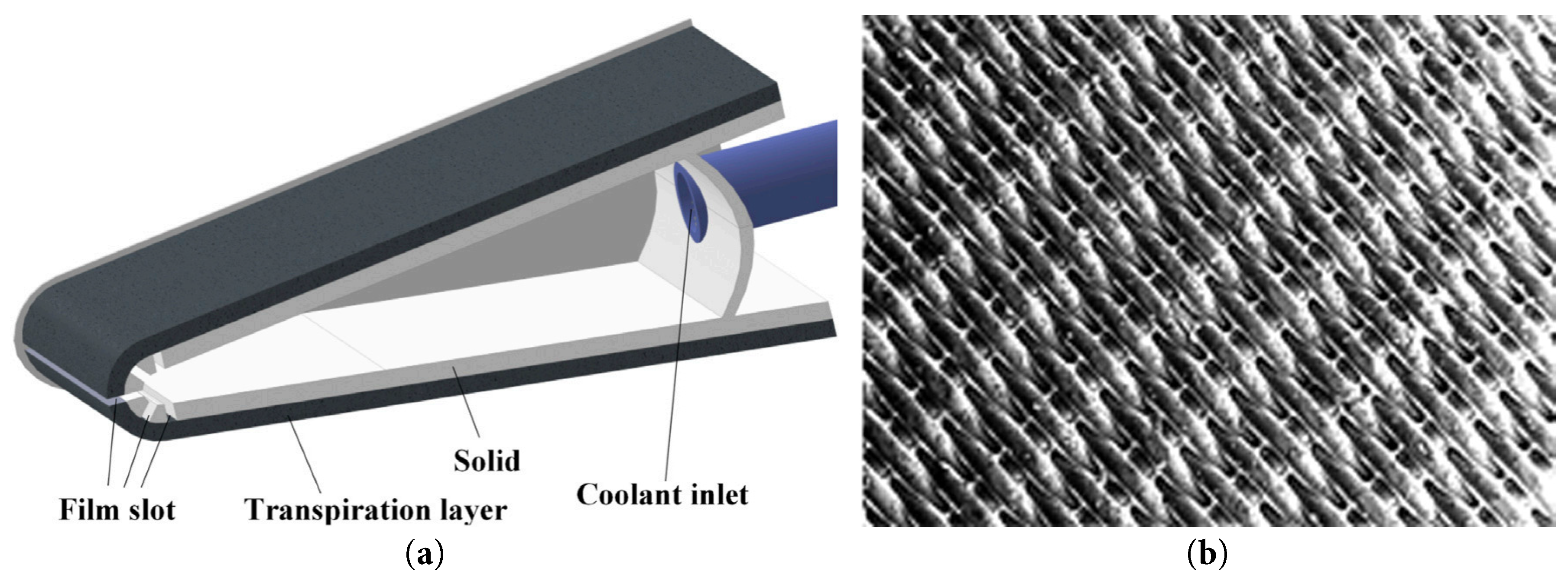
Figure 27: Porous transpiration cooling structures. (a) Double layer transpiration cooling in the leading edge; (b) sintered metal wire mesh structures.
2.4 Comparative Analysis of Engineering Trade-Offs
To provide practical guidance for engineering design, the three active cooling technologies are systematically compared in Table 2 based on multiple evaluation criteria.
Table 2: Comparative evaluation of three active cooling methods.
| Evaluation Criteria | Regenerative Cooling | Gas Film Cooling | Transpiration Cooling |
|---|---|---|---|
| Cooling Mechanism | Convective heat absorption by fuel flowing through channels | Protective gas film isolating hot gas | Uniform micro-porous permeation and phase change |
| Cooling Efficiency | High (sustained) | Moderate to High (localized) | Very High (uniform) |
| Coolant Consumption | Low (fuel reuse) | High | Low to Moderate |
| Structural Complexity | Complex (channel network) | Simple (holes/slots) | Very Complex (porous media) |
| Manufacturing Difficulty | Moderate | Low | Very High |
| Applicable Heat Flux | >10 MW/m2 | 5–15 MW/m2 | >20 MW/m2 |
| Primary Limitation | Coking and pressure drop | Rapid performance degradation downstream | Pore blockage and deformation |
From an engineering trade-off perspective, regenerative cooling excels in long-duration missions due to its energy recovery capability, but its application is constrained by the coking of hydrocarbon fuels and the significant pressure drop within micro-channels. Gas film cooling offers the simplest structural implementation and fastest thermal response; however, its effectiveness decays sharply downstream of the injection point, and the high coolant mass flow rate incurs a substantial thrust penalty. Transpiration cooling demonstrates superior cooling uniformity and the highest theoretical efficiency, yet its practical deployment remains hindered by the lack of reliable fabrication techniques for gradient porous structures and the risk of pore clogging under extreme thermal-mechanical loads. Therefore, the selection of an optimal cooling strategy must carefully weigh mission duration, available coolant supply, structural weight constraints, and manufacturing feasibility.
3 Future Prospects and Research Challenges
Although substantial progress has already been made, numerous fundamental challenges remain to be addressed before active cooling—of the type currently under investigation—can be successfully implemented for hypersonic vehicles.
3.1 Hybrid Multi-Mode Cooling Systems
Standard single-mode cooling approaches often prove inadequate for managing the extreme and highly non-uniform thermal loads encountered during hypersonic flight. Emerging research efforts should therefore prioritize synergistic or multi-modal cooling architectures—such as integrating transpiration cooling in the stagnation region with regenerative cooling in the downstream combustion chamber, or combining opposing-jet injection with film cooling to enhance thermal protection of the leading edge. A fundamental research objective is to realize adaptive mode transitions—that is, seamless, context-aware switching between distinct cooling mechanisms—across varying flight regimes.
3.2 Advanced Materials and Manufacturing
The performance of active cooling systems is fundamentally limited by the intrinsic material properties of their constituent components. In regenerative cooling, there is an urgent need for advanced anti-coking alloys and ceramic matrix composites (CMCs) with high thermal conductivity. For transpiration cooling, the development of functionally graded porous materials—featuring precisely engineered pore-size gradients—is critical. Additive manufacturing (AM) techniques, including selective laser melting (SLM) and binder jetting, offer unprecedented design freedom to fabricate complex internal cooling channels and customized porous architectures, thereby significantly enhancing system reliability and overall thermal performance.
3.3 Intelligent Thermal Management
The integration of embedded micro-sensors, real-time thermal measurement methodologies, and closed-loop adaptive control strategies represents a paradigm shift—from passive thermal shielding to active, responsive thermal management. By continuously adjusting coolant flow in response to localized heat flux measurements, such systems can operate near-optimally while minimizing excessive coolant consumption and structural material usage.
3.4 Ground Testing and Flight Validation
Persistent discrepancies between ground-test conditions and the actual flight environment remain a major impediment to advances in hypersonic technology. To narrow this gap, next-generation ground-testing facilities must accommodate significantly higher total enthalpy levels and substantially extend test durations. Flight-testing programs—such as the X-51A and Zircon-class initiatives—provide unique empirical data that are critical for validating complex numerical models and accelerating the practical development of hypersonic systems. Consequently, from a strategic perspective, sustained investment in integrated ground–flight validation efforts is essential to transition such technologies from laboratory concepts to operationally deployable systems.
The present text constitutes a literature review. A systematic search was conducted across PubMed, Web of Science, and the China National Knowledge Infrastructure (CNKI) databases, with coverage restricted to publications indexed through July 2026. Targeted keyword combinations—including “hypersonic vehicles,” “active cooling technologies,” “regenerative cooling,” “gas film cooling,” “transpiration cooling,” and “thermal protection systems”—were applied methodically to delineate the scope of the review. All reference lists of initially identified articles were manually screened to identify additional relevant studies. For full-text analysis, only peer-reviewed, rigorously evaluated publications were included; a total of 186 such articles were selected for comprehensive assessment and synthesis.
The active cooling technology for hypersonic vehicles serves as a cornerstone in enabling long-duration and reusable flight operations. At present, the primary technical approaches each exhibit distinct advantages and inherent limitations. Regenerative cooling is well-established but entails system complexity; gas film cooling offers simplicity and effectiveness, yet suffers from rapid performance degradation and high coolant consumption; transpiration cooling holds significant potential, though it remains constrained by material and manufacturing challenges. Given that no single technology can adequately address all operational requirements, the integration of multiple cooling methods has become an inevitable trend. Future development will focus on the following aspects:
- (1)Develop metal matrix, ceramic matrix, and carbon/carbon (C/C) matrix composites exhibiting exceptional resistance to ultra-high temperatures and oxidation, possessing high thermal conductivity, and featuring precisely controllable pore architectures.
- (2)Leverage high-precision, multi-field coupled simulation tools to enable multiscale, accurate simulations of supercritical flows, multiphase flows, thermochemical reactions, and material degradation, thereby guiding the optimization of design parameters.
- (3)Advanced manufacturing technologies—particularly additive manufacturing—will facilitate the integrated fabrication of complex flow channels for regenerative cooling and customized porous structures for transpiration cooling, significantly enhancing system performance and reliability.
- (4)Intelligent thermal management systems will achieve dynamic, optimal allocation of cooling resources through the integration of sensor networks, real-time thermal environment monitoring, and adaptive control algorithms.
Acknowledgement:
Funding Statement: This research was funded by Hunan Province Major Science and Technology Research and Development Project (Grant No. 2024GK1040).
Author Contributions: The authors confirm contribution to the paper as follows: investigation, Liang Yin, Youjia Gao and Lei Zhong; resources, Liang Yin; data curation, Liang Yin and Jie Ding; writing—original draft preparation, Liang Yin, Yun Zeng and Jun Hu; writing—review and editing, Liang Yin and Jie Ding; visualization, Liang Yin; supervision, Yongsheng Zhang and Xiangming Liu; project administration, Youjia Gao; funding acquisition, Lei Zhong. All authors reviewed and approved the final version of the manuscript.
Availability of Data and Materials: The data that support the findings of this study are available from the Corresponding Author, Linag Yin, upon reasonable request.
Ethics Approval: Not applicable.
Conflicts of Interest: The authors declare no conflicts of interest.
References
1. Sreeja R , Abhina K , Srinivas C , Devapal D , Devasia R . Advanced lightweight ceramic foams for hypersonic vehicles. Int J Energetic Mater Chem Prop. 2025; 24( 1): 43– 61. doi:10.1615/intjenergeticmaterialschemprop.2024055371. [Google Scholar] [CrossRef]
2. Afolabi SO , Malachi IO , Olawumi AO . Multiscale modeling and optimization of thermal barrier coatings for interface conditions. Colloids Surf A Physicochem Eng Asp. 2025; 725: 137658. doi:10.1016/j.colsurfa.2025.137658. [Google Scholar] [CrossRef]
3. Ma H , Zhang Q , He L , Wang Z , Wang L . Cooling injection effect on a transonic squealer tip: Part I: Experimental heat transfer results and CFD validation. J Eng Gas Turbines Power. 2017; 139( 5): 052506. doi:10.1115/1.4035175. [Google Scholar] [CrossRef]
4. Pandey KK , Murugan S . Thermal and experimental analyses of thermal barrier coated pistons. Int J Model Simul. 2025; 45( 1): 1– 19. doi:10.1080/02286203.2023.2176676. [Google Scholar] [CrossRef]
5. Pugazhendhi A , Kamarudin SK , Praveenkumar TR , Sekar M . Asymmetric injection and cross-flow effects on mixing and combustion in a hydrogen powered DLR scramjet propulsion system. Int J Hydrogen Energy. 2025; 143: 679– 90. doi:10.1016/j.ijhydene.2025.04.437. [Google Scholar] [CrossRef]
6. Marley CD , Driscoll JF . Optimization of active and passive thermal protection systems for a hypersonic vehicle. J Aircr. 2022; 59( 1): 173– 83. doi:10.2514/1.c036411. [Google Scholar] [CrossRef]
7. Zuppardi G , Mongelluzzo G . Aerodynamic data to design an active thermal protection system for SpaceLiner 7-1. J Spacecr Rocket. 2023; 60( 6): 2013– 7. doi:10.2514/1.a35665. [Google Scholar] [CrossRef]
8. Yang S , Zhao H , Zhuang N , Tang X . Thermal protection of the nuclear rocket engine nozzle based on regenerative cooling method. Int J Therm Sci. 2024; 204: 109201. doi:10.1016/j.ijthermalsci.2024.109201. [Google Scholar] [CrossRef]
9. Seleznev RK . History of scramjet propulsion development. J Phys Conf Ser. 2018; 1009: 012028. doi:10.1088/1742-6596/1009/1/012028. [Google Scholar] [CrossRef]
10. Yaseen M , Rawat SK , Khan U , Sarris IE , Khan H , Negi AS , et al. Computational analysis of heat and mass transfer flow of wall jet hybrid nanofluid with irregular heat source/sink effects and waste discharge concentration. J Magn Magn Mater. 2023; 588: 171434. doi:10.1016/j.jmmm.2023.171434. [Google Scholar] [CrossRef]
11. Yao W , Zhang X , Shao T , Zhang Y , Xu P , Li Y , et al. Numerical study of flow and heat transfer characteristics of the novel small-channel thermal protection component. Int J Therm Sci. 2025; 214: 109880. doi:10.1016/j.ijthermalsci.2025.109880. [Google Scholar] [CrossRef]
12. Uyanna O , Najafi H . Thermal protection systems for space vehicles: A review on technology development, current challenges and future prospects. Acta Astronaut. 2020; 176: 341– 56. doi:10.1016/j.actaastro.2020.06.047. [Google Scholar] [CrossRef]
13. Park J , Kim Y , Cha JH , Kim S , Choi O , Kim DC . Design and thermo-structural analysis of multiple composite layers with ablative materials for passive thermal protection systems. Sci Rep. 2026; 16: 12225. doi:10.1038/s41598-026-43658-7. [Google Scholar] [CrossRef]
14. Savino R , Mungiguerra S , Di Martino GD . Testing ultra-high-temperature ceramics for thermal protection and rocket applications. Adv Appl Ceram. 2018; 117( Suppl 1): s9– 18. doi:10.1080/17436753.2018.1509175. [Google Scholar] [CrossRef]
15. Sziroczak D , Smith H . A review of design issues specific to hypersonic flight vehicles. Prog Aerosp Sci. 2016; 84: 1– 28. doi:10.1016/j.paerosci.2016.04.001. [Google Scholar] [CrossRef]
16. Berthon-Fabry S , Hildenbrand C , Ilbizian P , Jones E , Tavera S . Evaluation of lightweight and flexible insulating aerogel blankets based on Resorcinol-Formaldehyde-Silica for space applications. Eur Polym J. 2017; 93: 403– 16. doi:10.1016/j.eurpolymj.2017.06.009. [Google Scholar] [CrossRef]
17. Miyakita T , Hatakenaka R , Sugita H , Saitoh M , Hirai T . Development of a new multi-layer insulation blanket with non-interlayer-contact spacer for space cryogenic mission. Cryogenics. 2014; 64: 112– 20. doi:10.1016/j.cryogenics.2014.04.008. [Google Scholar] [CrossRef]
18. Jie H , Weixing Y , Bin K , Jiayong Y , Man W , Qingmao Z . Two degree-of-freedom dynamic theoretical model on tile thermal protection system. Trans Nanjing Univ Aeronaut Astronaut. 2019; 36( 1): 139– 45. doi:10.16356/j.1005-1120.2019.01.013. [Google Scholar] [CrossRef]
19. Zhu Y , Peng W , Xu R , Jiang P . Review on active thermal protection and its heat transfer for airbreathing hypersonic vehicles. Chin J Aeronaut. 2018; 31( 10): 1929– 53. doi:10.1016/j.cja.2018.06.011. [Google Scholar] [CrossRef]
20. Fujii K , Inoue Y . Aerodynamic heating measurement on ceramic tile region of Hypersonic flight experiment (HYFLEX). In: Proceedings of the 36th AIAA Aerospace Sciences Meeting and Exhibit; 1998 Jan 12–15; Reno, NV, USA. doi:10.2514/6.1998-605. [Google Scholar] [CrossRef]
21. Franceschetti LT , Kihm KD , Rawal SP , White JR . Pulsating heat pipe performance modeling with liquid metal coolants under hypersonic aerothermal heating. J Thermophys Heat Transf. 2025; 39( 1): 185– 98. doi:10.2514/1.t6885. [Google Scholar] [CrossRef]
22. Scigliano R , De Simone V , Fusaro R , Ferretto D , Viola N . Numerical simulation of heat pipe thermal performance for aerospace cooling system applications. Aerospace. 2024; 11( 1): 85. doi:10.3390/aerospace11010085. [Google Scholar] [CrossRef]
23. Yao F , Zhang Y , Bai L , Zhang W , Hou Y , Fu J . Experimental study on a rectangular evaporator loop heat pipe with a phase-change material heat sink. Appl Therm Eng. 2024; 245: 122861. doi:10.1016/j.applthermaleng.2024.122861. [Google Scholar] [CrossRef]
24. Yu D , Liu J , Hu C , Mei H . Key features and highly effective prediction of complete startup from frozen state for high-temperature heat pipe in heat pipe reactor. Appl Therm Eng. 2024; 236: 121766. doi:10.1016/j.applthermaleng.2023.121766. [Google Scholar] [CrossRef]
25. Jiang G , Deng Z , Shi M , Zhang W , Liu Y , Cao W , et al. Ablation behavior of ZrSi2-B4C-modified carbon fiber/boron phenolic resin ceramizable composites at different heat fluxes. Ceram Int. 2025; 51( 15): 20643– 52. doi:10.1016/j.ceramint.2025.02.231. [Google Scholar] [CrossRef]
26. Li W , Huang J , Zhang Z , Huang H , Liang J , Wang L . Evaluation method and key factor analysis for thermal protection performance of multifunctional integrated ablative materials. Polym Compos. 2020; 41( 12): 5043– 58. doi:10.1002/pc.25773. [Google Scholar] [CrossRef]
27. Shi YA , Zha BL , Su QD , Wang JJ , Li SY . Thermal performance and ablation characteristics of C/C-SiC for thermal protection of hypersonic vehicle. J Eur Ceram Soc. 2021; 41( 11): 5427– 36. doi:10.1016/j.jeurceramsoc.2021.03.015. [Google Scholar] [CrossRef]
28. Wang J , Xie W , Yu D , Gao B , Yang F , Liu S , et al. Study on the multi-field coupling behavior of C/SiC composites under the combined action of the local extreme heat source and hypersonic airflow. Int J Therm Sci. 2024; 200: 108952. doi:10.1016/j.ijthermalsci.2024.108952. [Google Scholar] [CrossRef]
29. Glass DE , Camarda CJ , Merrigan MA , Sena JT , Reid RS . Fabrication and testing of a leading-edge-shaped heat pipe. J Spacecr Rockets. 1999; 36( 6): 921– 3. doi:10.2514/2.3515. [Google Scholar] [CrossRef]
30. Luo S , Xu D , Song J , Liu J . A review of regenerative cooling technologies for scramjets. Appl Therm Eng. 2021; 190: 116754. doi:10.1016/j.applthermaleng.2021.116754. [Google Scholar] [CrossRef]
31. Kose YM , Celik M . Regenerative cooling comparison of LOX/LCH4 and LOX/LC3H8 rocket engines using the one-dimensional regenerative cooling modelling tool ODREC. Appl Sci. 2024; 14( 1): 71. doi:10.3390/app14010071. [Google Scholar] [CrossRef]
32. Fry RS . A century of ramjet propulsion technology evolution. J Propuls Power. 2004; 20( 1): 27– 58. doi:10.2514/1.9178. [Google Scholar] [CrossRef]
33. Ko S , Gil Y , Park S . Development of RP-3 surrogate fuels via multi-objective genetic algorithm for regenerative cooling CFD with supercritical property fidelity. Aerospace. 2026; 13( 4): 307. doi:10.3390/aerospace13040307. [Google Scholar] [CrossRef]
34. Gibreel M , Jamea AMA , Adam A , Chen X , Elmouazen H , Wahballa H . Thermal performance and flow characteristics of supercritical hydrogen in variable-aspect-ratio regenerative cooling channels: A CFD investigation. Fluids. 2026; 11( 1): 7. doi:10.3390/fluids11010007. [Google Scholar] [CrossRef]
35. Gao Z , Bai J , Zhou J , Wang C , Li P . Numerical investigation of supercritical methane in helically coiled tube on regenerative cooling of liquid rocket electromechanical actuator. Cryogenics. 2020; 106: 103023. doi:10.1016/j.cryogenics.2019.103023. [Google Scholar] [CrossRef]
36. Li F , Li Z , Jing K , Wang L , Zhang X , Liu G . Thermal cracking of endothermic hydrocarbon fuel in regenerative cooling channels with different geometric structures. Energy Fuels. 2018; 32( 6): 6524– 34. doi:10.1021/acs.energyfuels.8b00531. [Google Scholar] [CrossRef]
37. Taddeo L , Gascoin N , Chetehouna K , Ingenito A , Stella F , Bouchez M , et al. Experimental study of pyrolysis–combustion coupling in a regeneratively cooled combustor: System dynamics analysis. Aerosp Sci Technol. 2017; 67: 473– 83. doi:10.1016/j.ast.2017.04.026. [Google Scholar] [CrossRef]
38. Chen Y , Wang Y , Bao Z , Zhang Q , Li XY . Numerical investigation of flow distribution and heat transfer of hydrocarbon fuel in regenerative cooling panel. Appl Therm Eng. 2016; 98: 628– 35. doi:10.1016/j.applthermaleng.2015.12.088. [Google Scholar] [CrossRef]
39. Sunden BA , Wu Z , Huang D . Comparison of heat transfer characteristics of aviation kerosene flowing in smooth and enhanced mini tubes at supercritical pressures. Int J Numer Meth Heat Fluid Flow. 2016; 26( 3/4): 1289– 308. doi:10.1108/hff-12-2015-0538. [Google Scholar] [CrossRef]
40. Liu Z , Yuan S , Gong S , Liu G . Long-term thermal oxidative deposition of RP-3 jet fuels: Mechanism and modeling. Fuel. 2021; 303: 121250. doi:10.1016/j.fuel.2021.121250. [Google Scholar] [CrossRef]
41. Jiang PX , Liu B , Zhao CR , Luo F . Convection heat transfer of supercritical pressure carbon dioxide in a vertical micro tube from transition to turbulent flow regime. Int J Heat Mass Transf. 2013; 56( 1–2): 741– 9. doi:10.1016/j.ijheatmasstransfer.2012.08.038. [Google Scholar] [CrossRef]
42. Heneghan SP , Zabarnick S . Oxidation of jet fuels and the formation of deposit. Fuel. 1994; 73( 1): 35– 43. doi:10.1016/0016-2361(94)90185-6. [Google Scholar] [CrossRef]
43. Katta VR , Jones EG , Roquemore WM . Modeling of deposition process in liquid fuels. Combust Sci Technol. 1998; 139( 1): 75– 111. doi:10.1080/00102209808952082. [Google Scholar] [CrossRef]
44. Doungthip T , Ervin JS , Zabarnick S , Williams TF . Simulation of the effect of metal-surface catalysis on the thermal oxidation of jet fuel. Energy Fuels. 2004; 18( 2): 425– 37. doi:10.1021/ef030098d. [Google Scholar] [CrossRef]
45. Kuprowicz NJ , Zabarnick S , West ZJ , Ervin JS . Use of measured species class concentrations with chemical kinetic modeling for the prediction of autoxidation and deposition of jet fuels. Energy Fuels. 2007; 21( 2): 530– 44. doi:10.1021/ef060391o. [Google Scholar] [CrossRef]
46. Hou LY , Dong N , Sun DP . Heat transfer and thermal cracking behavior of hydrocarbon fuel. Fuel. 2013; 103: 1132– 7. doi:10.1016/j.fuel.2012.09.021. [Google Scholar] [CrossRef]
47. Jia Z , Huang H , Zhou W , Qi F , Zeng M . Experimental and modeling investigation of n-decane pyrolysis at supercritical pressures. Energy Fuels. 2014; 28( 9): 6019– 28. doi:10.1021/ef5009314. [Google Scholar] [CrossRef]
48. Daniau E , Bouchez M , Herbinet O , Marquaire PM , Gascoin N , Gillard P . Fuel reforming for Scramjet thermal management and Combustion optimization. In: Proceedings of the AIAA/CIRA 13th International Space Planes and Hypersonics Systems and Technologies Conference; 2005 May 16–20; Capua, Italy. doi:10.2514/6.2005-3403. [Google Scholar] [CrossRef]
49. Depeyre D , Flicoteaux C , Chardaire C . Pure n-hexadecane thermal steam cracking. Ind Eng Chem Proc Des Dev. 1985; 24( 4): 1251– 8. doi:10.1021/i200031a059. [Google Scholar] [CrossRef]
50. Djimasbe R , Varfolomeev MA , Al-Muntaser AA , Yuan C , Suwaid MA , Feoktistov DA , et al. Deep insights into heavy oil upgrading using supercritical water by a comprehensive analysis of GC, GC-MS, NMR, and SEM-EDX with the aid of EPR as a complementary technical analysis. ACS Omega. 2021; 6( 1): 135– 47. doi:10.1021/acsomega.0c03974. [Google Scholar] [CrossRef]
51. Lucas P , Marchand A . Pyrolytic carbon deposition from methane: An analytical approach to the chemical process. Carbon. 1990; 28( 1): 207– 19. doi:10.1016/0008-6223(90)90115-f. [Google Scholar] [CrossRef]
52. Pengfei J . Physical properties of coke from the RP-3 kerosene. J Aerosp Power. 2018; 33( 8): 1880– 5. (In Chinese). doi:10.13224/j.cnki.jasp.2018.08.011. [Google Scholar] [CrossRef]
53. Taylor WF . Deposit formation from deoxygenated hydrocarbons. II. Effect of trace sulfur compounds. Prod R&D. 1976; 15( 1): 64– 8. doi:10.1021/i360057a012. [Google Scholar] [CrossRef]
54. Jin D , Mi J , Guo Y , Dai Y , Fang W . Evaporation and autoignition characteristics of JP-10 droplets with hyperbranched polyester as additive. Energies. 2023; 16( 8): 3333. doi:10.3390/en16083333. [Google Scholar] [CrossRef]
55. Strohm JJ . Significant reduction of carbon deposit by Hydrogen Donor addition to JP-8 jet fuel at high temperatures. Am Chem Soc Div Fuel Chem Prepr Symp. 2004; 49( 1): 34– 5. [Google Scholar]
56. Guo W , Zhang X , Liu G , Wang J , Zhao J , Mi Z . Roles of hydrogen donors and organic selenides in inhibiting solid deposits from thermal stressing of n-dodecane and Chinese RP-3 jet fuel. Ind Eng Chem Res. 2009; 48( 18): 8320– 7. doi:10.1021/ie900735c. [Google Scholar] [CrossRef]
57. Zhang X . Research on rocket Kerosene Pyrolysis. Tuijin Jishu J Propuls Technol. 2020; 41( 6): 1420– 7. (In Chinese). doi:10.13675/j.cnki.tjjs.190464. [Google Scholar] [CrossRef]
58. Lei Z , Bao Z . Heat transfer characteristics of n-Decane during Pyrolysis in a Rectangular tube. Adv Eng Sci. 2025; 57( 4): 342– 9. (In Chinese). doi:10.12454/j.jsuese.202300644. [Google Scholar] [CrossRef]
59. Zublev DG , Barsky VD , Trikilo AI . Coking temperatures. 3. Model of the temperature distribution in the heating channels. Coke Chem. 2021; 64( 9): 391– 6. doi:10.3103/s1068364x21090088. [Google Scholar] [CrossRef]
60. Wang J , Sun H , Jin H , Gao H , Wen D . Cooling performance of hydrocarbon fuels in the presence of pyrolysis and surface coking in cavity-shaped channels. Fuel. 2024; 365: 131232. doi:10.1016/j.fuel.2024.131232. [Google Scholar] [CrossRef]
61. Tao Z , Hu X , Zhu J , Cheng Z . Numerical study of flow and heat transfer of n-decane with pyrolysis and pyrolytic coking under supercritical pressures. Energy Fuels. 2017; 31( 8): 8698– 707. doi:10.1021/acs.energyfuels.7b01083. [Google Scholar] [CrossRef]
62. Li H , Wang X , Song Q , Yang Z , Qi W . Experimental investigation of n-heptane unsteady-state pyrolysis coking characteristics in microchannel. J Anal Appl Pyrolysis. 2022; 161( Suppl C): 105384. doi:10.1016/j.jaap.2021.105384. [Google Scholar] [CrossRef]
63. Zhang S , Cui N , Xiong Y , Feng Y , Qin J , Bao W . Effect of channel aspect ratio on chemical recuperation process in advanced aeroengines. Energy. 2017; 123: 9– 19. doi:10.1016/j.energy.2016.12.100. [Google Scholar] [CrossRef]
64. Bao W , Zhang S , Qin J , Zhou W , Xie K . Numerical analysis of flowing cracked hydrocarbon fuel inside cooling channels in view of thermal management. Energy. 2014; 67: 149– 61. doi:10.1016/j.energy.2014.01.044. [Google Scholar] [CrossRef]
65. Chang H , Pu H , Wang J , Mu L , Shang Y , Dong M . Numerical investigation on transient thermal and flow behaviors of convective heat transfer in a single-side heated rectangular channel with supercritical hydrocarbon fuel under unsteady heat flux. Int J Therm Sci. 2025; 218: 110179. doi:10.1016/j.ijthermalsci.2025.110179. [Google Scholar] [CrossRef]
66. Liu ZH , Bi QC , Guo Y , Ma XS , Yang ZQ , Yan JG , et al. Hydraulic and thermal effects of coke deposition during pyrolysis of hydrocarbon fuel in a mini-channel. Energy Fuels. 2012; 26( 6): 3672– 9. doi:10.1021/ef3008079. [Google Scholar] [CrossRef]
67. Feng Y , Cao Y , Liu S , Qin J , Hemeda AA , Ma Y . The influence of coking on heat transfer in turbulent reacting flow of supercritical hydrocarbon fuels. Int J Heat Mass Transf. 2019; 144: 118623. doi:10.1016/j.ijheatmasstransfer.2019.118623. [Google Scholar] [CrossRef]
68. Taddeo L , Gascoin N , Chetehouna K , Ingenito A , Stella F , Bouchez M , et al. Experimental study of pyrolysis-combustion coupling in a regeneratively cooled combustor: Heat transfer and coke formation. Fuel. 2019; 239: 1091– 101. doi:10.1016/j.fuel.2018.11.096. [Google Scholar] [CrossRef]
69. Shanmugam AR , Silvi LD , Park KS . Active cooling performance enhancement of supercritical hydrogen with arc-ribs for a hypersonic vehicle leading edge. Int Commun Heat Mass Transf. 2025; 168: 109519. doi:10.1016/j.icheatmasstransfer.2025.109519. [Google Scholar] [CrossRef]
70. Choudhury SP , Suryan A , Pisharady JC , Jayashree A , Rashid K . Parametric study of supersonic film cooling in dual bell nozzle for an experimental air–kerosene engine. Aerosp Sci Technol. 2018; 78: 364– 76. doi:10.1016/j.ast.2018.04.038. [Google Scholar] [CrossRef]
71. Lee SH . Mixing augmentation with cooled pylon injection in a scramjet combustor. J Propuls Power. 2012; 28( 3): 477– 85. doi:10.2514/1.b34220. [Google Scholar] [CrossRef]
72. Su C . Aero-optical analysis of a film-cooled optical window based on linear stability analysis. AIAA J. 2019; 57( 7): 2840– 50. doi:10.2514/1.j058150. [Google Scholar] [CrossRef]
73. Sun XW , Yang XL , Liu W . Aero-optical and aero-heating effects of supersonic turbulent boundary layer with a tangential wall-injection film. Phys Fluids. 2021; 33( 3): 035118. doi:10.1063/5.0044025. [Google Scholar] [CrossRef]
74. Wang J , Wang W , Li G , Luo D , Wu J . Numerical study of the cooling performance of Rupert-shaped film cooling holes. Int J Therm Sci. 2024; 198: 108859. doi:10.1016/j.ijthermalsci.2023.108859. [Google Scholar] [CrossRef]
75. Kim JH , Kang C . A novel design for film-cooling: Cooling holes with inlet groove. Int J Therm Sci. 2024; 195: 108649. doi:10.1016/j.ijthermalsci.2023.108649. [Google Scholar] [CrossRef]
76. Wang K , Zhang X , Liu S , Wang P , Zhou W , Wen X , et al. Transonic vane film cooling with shaped sweeping jet design. Int J Therm Sci. 2025; 208: 109507. doi:10.1016/j.ijthermalsci.2024.109507. [Google Scholar] [CrossRef]
77. Krishna Anand VG , Parammasivam KM . Thermal barrier coated surface modifications for gas turbine film cooling: A review. J Therm Anal Calorim. 2021; 146( 2): 545– 80. doi:10.1007/s10973-020-10032-2. [Google Scholar] [CrossRef]
78. Keller MA , Kloker MJ , Olivier H . Influence of cooling-gas properties on film-cooling effectiveness in supersonic flow. J Spacecr Rockets. 2015; 52( 5): 1443– 55. doi:10.2514/1.a33203. [Google Scholar] [CrossRef]
79. Gustafsson KMB , Johansson TG . An experimental study of surface temperature distribution on effusion-cooled plates. J Eng Gas Turbines Power. 2001; 123( 2): 308– 16. doi:10.1115/1.1364496. [Google Scholar] [CrossRef]
80. Huang Y , Zhang JZ , Wang CH . Multi-objective optimization of round-to-slot film cooling holes on a flat surface. Aerosp Sci Technol. 2020; 100: 105737. doi:10.1016/j.ast.2020.105737. [Google Scholar] [CrossRef]
81. Zhang J , Zhang S , Wang C , Tan X . Recent advances in film cooling enhancement: A review. Chin J Aeronaut. 2020; 33( 4): 1119– 36. doi:10.1016/j.cja.2019.12.023. [Google Scholar] [CrossRef]
82. Abdala AMM , Elwekeel FNM . An influence of novel upstream steps on film cooling performance. Int J Heat Mass Transf. 2016; 93: 86– 96. doi:10.1016/j.ijheatmasstransfer.2015.10.007. [Google Scholar] [CrossRef]
83. Zhang SC , Zhang JZ , Tan XM . Numerical investigation of film cooling enhancement using an upstream sand-dune-shaped ramp. Computation. 2018; 6( 3): 49. doi:10.3390/computation6030049. [Google Scholar] [CrossRef]
84. Linn J , Kloker MJ . Effects of wall-temperature conditions on effusion cooling in a supersonic boundary layer. AIAA J. 2011; 49( 2): 299– 307. doi:10.2514/1.j050383. [Google Scholar] [CrossRef]
85. Feldhusen-Hoffmann A , Statnikov V , Klaas M , Schröder W . Investigation of shock–acoustic-wave interaction in transonic flow. Exp Fluids. 2017; 59( 1): 15. doi:10.1007/s00348-017-2466-z. [Google Scholar] [CrossRef]
86. Goldstein RJ . Film cooling. In: Advances in heat transfer. Vol. 7. Amsterdam, The Netherlands: Elsevier; 1971. p. 321– 79. doi:10.1016/s0065-2717(08)70020-0. [Google Scholar] [CrossRef]
87. Gülhan A , Braun S . An experimental study on the efficiency of transpiration cooling in laminar and turbulent hypersonic flows. Exp Fluids. 2011; 50( 3): 509– 25. doi:10.1007/s00348-010-0945-6. [Google Scholar] [CrossRef]
88. Peng W , Jiang PX . Influence of shock waves on supersonic film cooling. J Spacecr Rockets. 2009; 46( 1): 67– 73. doi:10.2514/1.38458. [Google Scholar] [CrossRef]
89. Ni H , Jiang P , Peng W , Sun X , Zhu Y . An innovative design for measuring the enhanced mixing effect of a shock wave on supersonic film cooling. Int Commun Heat Mass Transf. 2021; 122: 105132. doi:10.1016/j.icheatmasstransfer.2021.105132. [Google Scholar] [CrossRef]
90. Keller MA , Kloker MJ . Direct numerical simulation of foreign-gas film cooling in supersonic boundary-layer flow. AIAA J. 2017; 55( 1): 99– 111. doi:10.2514/1.j055115. [Google Scholar] [CrossRef]
91. Kim GM , Jeong JY , Kang YJ , Kwak JS . A comparative study of purge slot exit shape on the film cooling effectiveness of a gas turbine shroud. Int J Therm Sci. 2024; 197: 108762. doi:10.1016/j.ijthermalsci.2023.108762. [Google Scholar] [CrossRef]
92. Peter JMF , Kloker MJ . Direct numerical simulation of supersonic turbulent flow with film cooling by wall-parallel blowing. Phys Fluids. 2022; 34( 2): 025125. doi:10.1063/5.0080049. [Google Scholar] [CrossRef]
93. Juhany KA , Hunt ML . Flowfield measurements in supersonic film cooling including the effect of shock-wave interaction. AIAA J. 1994; 32( 3): 578– 85. doi:10.2514/3.12024. [Google Scholar] [CrossRef]
94. Cai H , Liao H , Li H , Zhu C , You Y . Film cooling and its combination with thermal barrier coating for hypersonic engine. Int J Therm Sci. 2025; 217: 110078. doi:10.1016/j.ijthermalsci.2025.110078. [Google Scholar] [CrossRef]
95. Konopka M , Meinke M , Schröder W . Large-eddy simulation of shock/cooling-film interaction. AIAA J. 2012; 50( 10): 2102– 14. doi:10.2514/1.j051405. [Google Scholar] [CrossRef]
96. Sun X , Ni H , Peng W , Jiang P , Zhu Y . Influence of shock wave impinging region on supersonic film cooling. Chin J Aeronaut. 2021; 34( 5): 452– 65. doi:10.1016/j.cja.2020.12.012. [Google Scholar] [CrossRef]
97. Zhang J , Xie H , Yang C . Numerical study of flow and heat transfer characteristics of impingement/effusion cooling. Chin J Aeronaut. 2009; 22( 4): 343– 8. doi:10.1016/s1000-9361(08)60109-0. [Google Scholar] [CrossRef]
98. Rozati A , Tafti DK . Effect of coolant–mainstream blowing ratio on leading edge film cooling flow and heat transfer–LES investigation. Int J Heat Fluid Flow. 2008; 29( 4): 857– 73. doi:10.1016/j.ijheatfluidflow.2008.02.007. [Google Scholar] [CrossRef]
99. Saumweber C , Schulz A , Wittig S . Free-stream turbulence effects on film cooling with shaped holes. J Turbomach. 2003; 125( 1): 65– 73. doi:10.1115/1.1515336. [Google Scholar] [CrossRef]
100. Lee SH . Characteristics of dual transverse injection in scramjet combustor, part 1: Mixing. J Propuls Power. 2006; 22( 5): 1012– 9. doi:10.2514/1.14180. [Google Scholar] [CrossRef]
101. Wang L , Ma R , Liu B , Li S . Autonomous cooling design and temperature control mechanism of hypersonic vehicle. Heat Transf Eng. 2026; 47( 2): 193– 204. doi:10.1080/01457632.2024.2437893. [Google Scholar] [CrossRef]
102. Love ES . The effects of a small jet of air exhausting from the nose of a body of revolution in supersonic flow. Washington, DC, USA: NASA; 1952. Report No.: NACA-RM-L52I19a. [Google Scholar]
103. Rashid S , Nawaz F , Maqsood A , Salamat S , Riaz R . Effect of opposing jet on aerodynamic and flight stability characteristics of a generic supersonic slender forebody. J Mech Sci Technol. 2022; 36( 6): 2923– 36. doi:10.1007/s12206-022-0524-9. [Google Scholar] [CrossRef]
104. Ahmed MYM , Qin N . Forebody shock control devices for drag and aero-heating reduction: A comprehensive survey with a practical perspective. Prog Aerosp Sci. 2020; 112: 100585. doi:10.1016/j.paerosci.2019.100585. [Google Scholar] [CrossRef]
105. Sun XW , Huang W , Guo ZY , Yan L . Multiobjective design optimization of hypersonic combinational novel cavity and opposing jet concept. J Spacecr Rockets. 2017; 54( 3): 662– 71. doi:10.2514/1.a33801. [Google Scholar] [CrossRef]
106. Huang W . A survey of drag and heat reduction in supersonic flows by a counterflowing jet and its combinations. J Zhejiang Univ Sci A. 2015; 16( 7): 551– 61. doi:10.1631/jzus.a1500021. [Google Scholar] [CrossRef]
107. Gerdroodbary MB , Imani M , Ganji DD . Investigation of film cooling on nose cone by a forward facing array of micro-jets in Hypersonic flow. Int Commun Heat Mass Transf. 2015; 64: 42– 9. doi:10.1016/j.icheatmasstransfer.2015.02.015. [Google Scholar] [CrossRef]
108. Li S , Huang W , Lei J , Wang Z . Drag and heat reduction mechanism of the porous opposing jet for variable blunt hypersonic vehicles. Int J Heat Mass Transf. 2018; 126: 1087– 98. doi:10.1016/j.ijheatmasstransfer.2018.06.054. [Google Scholar] [CrossRef]
109. Li SB , Zhang TT , Ou C , Huang W , Chen J . Mechanism study on drag reduction and thermal protection for the porous opposing jet in hypersonic flow. Aerosp Sci Technol. 2020; 103: 105933. doi:10.1016/j.ast.2020.105933. [Google Scholar] [CrossRef]
110. Ji C , Liu B , Li SB , Huang W , Yan L . Parametric investigation on drag reduction and thermal protection characteristics of the porous opposing jet in the hypersonic flow. Aerosp Sci Technol. 2021; 116: 106867. doi:10.1016/j.ast.2021.106867. [Google Scholar] [CrossRef]
111. Gao G , Liu B , Huang W , Ji C , Niu Y . Review of opposing jet drag reduction and thermal protection technology for hypersonic vehicle. Tactical Missile Technol. 2021;( 4): 67– 75. (In Chinese). doi:10.16358/j.issn.1009-1300.2021.1.049. [Google Scholar] [CrossRef]
112. Deng F , Xie F , Qin N , Huang W , Wang L , Chu H . Drag reduction investigation for hypersonic lifting-body vehicles with aerospike and long penetration mode counterflowing jet. Aerosp Sci Technol. 2018; 76: 361– 73. doi:10.1016/j.ast.2018.01.039. [Google Scholar] [CrossRef]
113. Deng F , Xie F , Huang W , Dong H , Zhang D . Numerical exploration on jet oscillation mechanism of counterflowing jet ahead of a hypersonic lifting-body vehicle. Sci China Technol Sci. 2018; 61( 7): 1056– 71. doi:10.1007/s11431-017-9135-0. [Google Scholar] [CrossRef]
114. Shang JS , Hayes J , Wurtzler K , Strang W . Jet-Spike Bifurcation in high-speed flows. AIAA J. 2001; 39( 6): 1159– 65. doi:10.2514/2.1430. [Google Scholar] [CrossRef]
115. Kim Y , Roh TS , Huh H , Lee HJ . Study on the combined effect of various injection conditions on the drag reduction by a counter-flow jet in supersonic flow. Aerosp Sci Technol. 2020; 98: 105580. doi:10.1016/j.ast.2019.105580. [Google Scholar] [CrossRef]
116. Dong H , Zhang X , Liu S , Cheng K , Zhao W . Numerical and experimental study on opposing jet in hypersonic flow. Acta Aerodyn Sin. 2022; 40( 4): 101– 9. (In Chinese). doi:10.7638/kqdlxxb-2021.0240. [Google Scholar] [CrossRef]
117. Hayashi K , Aso S . Effect of pressure ratio on aerodynamic heating reduction due to opposing jet. In: Proceedings of the 36th AIAA Thermophysics Conference; 2003 Jun 23–26; Orlando, FL, USA. doi:10.2514/6.2003-4041. [Google Scholar] [CrossRef]
118. Hayashi K , Aso S , Tani Y . Experimental study on thermal protection system by opposing jet in supersonic flow. J Spacecr Rockets. 2006; 43( 1): 233– 5. doi:10.2514/1.15332. [Google Scholar] [CrossRef]
119. Finley PJ . The flow of a jet from a body opposing a supersonic free stream. J Fluid Mech. 1966; 26( 2): 337– 68. doi:10.1017/s0022112066001277. [Google Scholar] [CrossRef]
120. Venukumar B , Jagadeesh G , Reddy KPJ . Counterflow drag reduction by supersonic jet for a blunt body in hypersonic flow. Phys Fluids. 2006; 18( 11): 118104. doi:10.1063/1.2401623. [Google Scholar] [CrossRef]
121. Venukumar B , Reddy KPJ . Experimental investigation of drag reduction by forward facing high speed gas jet for a large angle blunt cone at Mach 8. Sadhana. 2007; 32( 1): 123– 31. doi:10.1007/s12046-007-0011-0. [Google Scholar] [CrossRef]
122. Bazyma LA , Rashkovan VM . Stabilization of blunt nose cavity flows by using energy deposition. J Spacecr Rockets. 2005; 42( 5): 790– 4. doi:10.2514/1.12145. [Google Scholar] [CrossRef]
123. Lu H , Liu W . Investigation of thermal protection system by forward-facing cavity and opposing jet combinatorial configuration. Chin J Aeronaut. 2013; 26( 2): 287– 93. doi:10.1016/j.cja.2013.02.005. [Google Scholar] [CrossRef]
124. Khamooshi A , Taylor T , Riggins DW . Drag and heat transfer reductions in high-speed flows. AIAA J. 2007; 45( 10): 2401– 13. doi:10.2514/1.29062. [Google Scholar] [CrossRef]
125. Saravanan S , Jagadeesh G , Reddy KPJ . Investigation of missile-shaped body with forward-facing cavity at Mach 8. J Spacecr Rockets. 2009; 46( 3): 577– 91. doi:10.2514/1.38914. [Google Scholar] [CrossRef]
126. Huang W , Liu J , Xia ZX . Drag reduction mechanism induced by a combinational opposing jet and spike concept in supersonic flows. Acta Astronaut. 2015; 115: 24– 31. doi:10.1016/j.actaastro.2015.04.025. [Google Scholar] [CrossRef]
127. Huang W , Yan L , Liu J , Jin L , Tan JG . Drag and heat reduction mechanism in the combinational opposing jet and acoustic cavity concept for hypersonic vehicles. Aerosp Sci Technol. 2015; 42: 407– 14. doi:10.1016/j.ast.2015.01.029. [Google Scholar] [CrossRef]
128. Lu HB , Liu WQ . Research on thermal protection mechanism of forward-facing cavity and opposing jet combinatorial thermal protection system. Heat Mass Transf. 2014; 50( 4): 449– 56. doi:10.1007/s00231-013-1247-3. [Google Scholar] [CrossRef]
129. Lu HB , Liu WQ . Effect of cavity physical dimension on forward facing cavity and opposing jet thermal protection system cooling efficiency. J Aerosp Power. 2012; 27( 12): 2666– 73. (In Chinese). doi:10.13224/j.cnki.jasp.2012.12.010. [Google Scholar] [CrossRef]
130. Ou M , Yan L , Huang W , Zhang TT . Design exploration of combinational spike and opposing jet concept in hypersonic flows based on CFD calculation and surrogate model. Acta Astronaut. 2019; 155: 287– 301. doi:10.1016/j.actaastro.2018.12.012. [Google Scholar] [CrossRef]
131. Teng H , Zhou L , Yang P , Jiang Z . Numerical investigation of wavelet features in rotating detonations with a two-step induction-reaction model. Int J Hydrogen Energy. 2020; 45( 7): 4991– 5001. doi:10.1016/j.ijhydene.2019.12.063. [Google Scholar] [CrossRef]
132. Jiang Z , Liu Y , Han G , Zhao W . Experimental demonstration of a new concept of drag reduction and thermal protection for hypersonic vehicles. Acta Mech Sin. 2009; 25( 3): 417– 9. doi:10.1007/s10409-009-0252-8. [Google Scholar] [CrossRef]
133. Liu Y , Jiang Z . Concept of non-ablative thermal protection system for hypersonic vehicles. AIAA J. 2013; 51( 3): 584– 90. doi:10.2514/1.j051875. [Google Scholar] [CrossRef]
134. Aswin G , Chakraborty D . Numerical simulation of transverse side jet interaction with supersonic free stream. Aerosp Sci Technol. 2010; 14( 5): 295– 301. doi:10.1016/j.ast.2010.02.001. [Google Scholar] [CrossRef]
135. Xu Y , Chen X . Drag and heat flux reduction performance of supersonic vehicle with combination model of aerospike/aerodisk and double jet. Hangkong Dongli Xuebao J Aerosp Power. 2024; 39( 5). (In Chinese). doi:10.13224/j.cnki.jasp.20220351. [Google Scholar] [CrossRef]
136. Deng F , Jiao Z , Liang B , Xie F , Qin N . Spike effects on drag reduction for hypersonic lifting body. J Spacecr Rockets. 2017; 54( 6): 1185– 95. doi:10.2514/1.a33865. [Google Scholar] [CrossRef]
137. Huang G , Zhu YH , Huang Z , Jiang PX . Investigation of combined transpiration and opposing jet cooling of sintered metal porous struts. Heat Transf Eng. 2018; 39( 7–8): 711– 23. doi:10.1080/01457632.2017.1325693. [Google Scholar] [CrossRef]
138. Jiang PX , Huang G , Zhu Y , Liao Z , Huang Z . Experimental investigation of combined transpiration and film cooling for sintered metal porous struts. Int J Heat Mass Transf. 2017; 108: 232– 43. doi:10.1016/j.ijheatmasstransfer.2016.12.014. [Google Scholar] [CrossRef]
139. Jia J , Zhang Y . Heat flux and pressure reduction using aerospike and counterflowing jet on complex hypersonic flow. Int J Aeronaut Space Sci. 2020; 21( 2): 337– 46. doi:10.1007/s42405-019-00227-9. [Google Scholar] [CrossRef]
140. Rong Y , Liu W . Research on cooling effect with coolant groove structure parameters in platelet transpiration cooled nosetip. J Therm Sci. 2010; 19( 5): 438– 44. doi:10.1007/s11630-010-0406-9. [Google Scholar] [CrossRef]
141. Shang S , Xiang S , Jiang L , Yang Y , Sun J . Effect of different hole shapes on hypersonic counter-jet film cooling. Hangkong Dongli Xuebao J Aerosp Power. 2020; 35( 8): 1612– 21. (In Chinese). doi:10.13224/j.cnki.jasp.2020.08.006. [Google Scholar] [CrossRef]
142. Zhou L , Xu C . The heat reduction performance at sharp leading edges of an X-51A-like aircraft with porous counterflowing jet. Zhongshan Daxue Xuebao/Acta Sci Natralium Univ Sunyatseni. 2023; 62( 2): 156– 64. (In Chinese). doi:10.13471/j.cnki.acta.snus.2022B038. [Google Scholar] [CrossRef]
143. Li SB , Wang ZG , Huang W , Yan L . Analysis of flowfield characteristics for equal polygon opposing jet on different freeflow conditions. Acta Astronaut. 2017; 133: 50– 62. doi:10.1016/j.actaastro.2017.01.011. [Google Scholar] [CrossRef]
144. Fan WJ , Li SB , Zhou J , Huang W , Ou M , Zhang RR . Study on the drag and heat reduction performance of porous opposing jet in hypersonic flow. Int J Heat Mass Transf. 2019; 139: 351– 61. doi:10.1016/j.ijheatmasstransfer.2019.05.035. [Google Scholar] [CrossRef]
145. Sriram R , Jagadeesh G . Film cooling at hypersonic Mach numbers using forward facing array of micro-jets. Int J Heat Mass Transf. 2009; 52( 15–16): 3654– 64. doi:10.1016/j.ijheatmasstransfer.2009.02.035. [Google Scholar] [CrossRef]
146. Rong Y , Wei Y , Zhan R . Research on thermal protection by opposing jet and transpiration for high speed vehicle. Aerosp Sci Technol. 2016; 48: 322– 7. doi:10.1016/j.ast.2015.11.014. [Google Scholar] [CrossRef]
147. Shen BX , Liu WQ . Effect of hot fuel gas on a combinational opposing jet and platelet transpiration thermal protection system. Appl Therm Eng. 2020; 164: 114513. doi:10.1016/j.applthermaleng.2019.114513. [Google Scholar] [CrossRef]
148. Shen B , Yin L , Liu H , Liu W . Thermal protection characteristics for a combinational opposing jet and platelet transpiration cooling nose-tip. Acta Astronaut. 2019; 155: 143– 52. doi:10.1016/j.actaastro.2018.11.052. [Google Scholar] [CrossRef]
149. Shen B , Yin L , Zhang X , Liu W . Investigation on cooling effect with a combinational opposing jet and platelet transpiration concept in hypersonic flow. Aerosp Sci Technol. 2019; 85: 399– 408. doi:10.1016/j.ast.2018.11.021. [Google Scholar] [CrossRef]
150. Bian Y , Liu X , Zheng J , Diao Y , Zhou W , Yanovskiy L . Numerical investigation on thermal insulation effect by coolant layer in performance of transpiration cooling. Int J Therm Sci. 2025; 214: 109856. doi:10.1016/j.ijthermalsci.2025.109856. [Google Scholar] [CrossRef]
151. Cerminara A , Nayak R , Potts J , Tanno H , Kloker MJ , Saikia B , et al. Transpiration cooling in hypersonic flow and mutual effect on turbulent transition and cooling performance. Phys Fluids. 2025; 37( 2): 026139. doi:10.1063/5.0253164. [Google Scholar] [CrossRef]
152. Hillcoat S , Hickey JP . Pressure–velocity coupling in transpiration cooling. Int J Heat Mass Transf. 2025; 239: 126532. doi:10.1016/j.ijheatmasstransfer.2024.126532. [Google Scholar] [CrossRef]
153. Heo J , Cho J , Addo-Akoto R , Lee J , Kim SJ , Han JH . Experimental investigation into the effect of coolant temperature on transpiration cooling in lattice structures. J Mech Sci Technol. 2026; 40( 2): 1445– 57. doi:10.1007/s12206-026-0158-4. [Google Scholar] [CrossRef]
154. Lu S , Zhu Q , Gong J , Chen H , Ying H . Experimental study on transpiration cooling with phase change in rotating detonation engine. Appl Therm Eng. 2025; 258: 124633. doi:10.1016/j.applthermaleng.2024.124633. [Google Scholar] [CrossRef]
155. Ko DD , Mannion A , Zhong X , Ju YS . Parametric study of transpiration cooling using oxides for sharp hypersonic leading edges. J Thermophys Heat Transf. 2025; 39( 1): 38– 52. doi:10.2514/1.t6991. [Google Scholar] [CrossRef]
156. Härter J , Veyskarami M , Schneider M , Müller JC , Wu H , Helmig R , et al. Self-pumping transpiration cooling: A joint experimental and numerical study. Transp Porous Med. 2025; 152( 8): 56. doi:10.1007/s11242-025-02198-w. [Google Scholar] [CrossRef]
157. Ding L , Wei K , Zhang Q , Wang J . An experimental investigation on transpiration cooling of porous flat plate. In: Proceedings of the 2011 International Conference on Remote Sensing, Environment and Transportation Engineering; 2011 Jun 24–26; Nanjing, China. p. 5692– 6. doi:10.1109/rsete.2011.5965645. [Google Scholar] [CrossRef]
158. Xiong YB , Zhu YH , Jiang PX . Numerical simulation of transpiration cooling for sintered metal porous strut of the scramjet combustion chamber. Heat Transf Eng. 2014; 35( 6–8): 721– 9. doi:10.1080/01457632.2013.837790. [Google Scholar] [CrossRef]
159. Xu G , Liu Y , Luo X , Ma J , Li H . Experimental investigation of transpiration cooling for sintered woven wire mesh structures. Int J Heat Mass Transf. 2015; 91: 898– 907. doi:10.1016/j.ijheatmasstransfer.2015.07.060. [Google Scholar] [CrossRef]
160. Vikulin AV , Yaroslavtsev NL , Zemlyanaya VA . Investigation into transpiration cooling of blades in high-temperature gas turbines. Therm Eng. 2019; 66( 6): 397– 401. doi:10.1134/s0040601519060090. [Google Scholar] [CrossRef]
161. Sun J , Cai G . Cooling performance of hydrogen for transpiration cooling structure made by different materials. Hangkong Dongli Xuebao J Aerosp Power. 2022; 37( 4): 781– 90. (In Chinese). doi:10.13224/j.cnki.jasp.20210187. [Google Scholar] [CrossRef]
162. Zhang B , Huang H , Huang J , Chen J . An experimental investigation on performance of transpiration cooling with liquid water through C/SiC porous ceramic. Appl Therm Eng. 2020; 178: 115526. doi:10.1016/j.applthermaleng.2020.115526. [Google Scholar] [CrossRef]
163. Zhang B , Huang H , Lu X , Peng J . Experimental investigation on transpiration cooling for porous ceramic with liquid water. Acta Astronaut. 2020; 167: 117– 21. doi:10.1016/j.actaastro.2019.11.009. [Google Scholar] [CrossRef]
164. König V , Rom M , Müller S , Selzer M , Schweikert S , Von Wolfersdorf J . Numerical and experimental investigation of transpiration cooling with carbon/carbon characteristic outflow distributions. J Thermophys Heat Transf. 2019; 33( 2): 449– 61. doi:10.2514/1.t5457. [Google Scholar] [CrossRef]
165. Zhen Y , Li Y , Liu X , Jia Z , Zhou W . Study on transpiration cooling of microchannel in liquid rocket thrust chamber. K Cheng Je Wu Li Hsueh Pao/J Eng Thermophys. 2025; 46( 5): 1594– 605. (In Chinese). [Google Scholar]
166. Liu Y , Yang W , Jiang L . Heat transfer characteristics of platelet transpiration-cooling thrust chamber. Ranshao Kexue Yu Jishu/J Combust Sci Technol. 2006; 12( 5): 423– 6. (In Chinese). [Google Scholar]
167. Shen BX , Liu HP , Liu WQ . Influence of angle of attack on a combined opposing jet and platelet transpiration cooling blunt nose in hypersonic vehicle. J Zhejiang Univ Sci A. 2020; 21( 9): 761– 9. doi:10.1631/jzus.a1900514. [Google Scholar] [CrossRef]
168. Shen B , Liu W . Insulating and absorbing heat of transpiration in a combinational opposing jet and platelet transpiration blunt body for hypersonic vehicle. Int J Heat Mass Transf. 2019; 138: 314– 25. doi:10.1016/j.ijheatmasstransfer.2019.04.057. [Google Scholar] [CrossRef]
169. He F , Wu N , Ran F , Wang J . Numerical investigation on the transpiration cooling of three-dimensional hypersonic inlet. Aerosp Sci Technol. 2020; 106: 106152. doi:10.1016/j.ast.2020.106152. [Google Scholar] [CrossRef]
170. Zhang X , Yan G , Yu X , Li H , Zhang Y , Song Y . Effects of particle diameter and plate thickness on transpiration cooling for double-layer porous plates. Front Energy Res. 2022; 10: 1050399. doi:10.3389/fenrg.2022.1050399. [Google Scholar] [CrossRef]
171. Shen L , Wang J , Dong W , Pu J , Peng J , Qu D , et al. An experimental investigation on transpiration cooling with phase change under supersonic condition. Appl Therm Eng. 2016; 105: 549– 56. doi:10.1016/j.applthermaleng.2016.03.039. [Google Scholar] [CrossRef]
172. Chen Y , Du S , Li D , Gao Y , He YL . Numerical investigation of transient phase-change transpiration cooling based on variable properties of coolant. Appl Therm Eng. 2021; 184: 116204. doi:10.1016/j.applthermaleng.2020.116204. [Google Scholar] [CrossRef]
173. Hu H , Jiang P , Ouyang X , Zhao C , Xu R . A modified energy equation model for flow boiling in porous media and its application to transpiration cooling at low pressures with transient effect. Int J Heat Mass Transf. 2020; 158: 119745. doi:10.1016/j.ijheatmasstransfer.2020.119745. [Google Scholar] [CrossRef]
174. Su H , Wang J , He F , Chen L , Ai B . Numerical investigation on transpiration cooling with coolant phase change under hypersonic conditions. Int J Heat Mass Transf. 2019; 129: 480– 90. doi:10.1016/j.ijheatmasstransfer.2018.09.123. [Google Scholar] [CrossRef]
175. Xiao X , Zhao G , Zhou W . Numerical investigation of transpiration cooling for porous nose cone with liquid coolant. Int J Heat Mass Transf. 2018; 121: 1297– 306. doi:10.1016/j.ijheatmasstransfer.2018.01.029. [Google Scholar] [CrossRef]
176. van Foreest A , Sippel M , Gülhan A , Esser B , Ambrosius BAC , Sudmeijer K . Transpiration cooling using liquid water. J Thermophys Heat Transf. 2009; 23( 4): 693– 702. doi:10.2514/1.39070. [Google Scholar] [CrossRef]
177. Wang J , Zhao L , Wang X , Ma J , Lin J . An experimental investigation on transpiration cooling of wedge shaped nose cone with liquid coolant. Int J Heat Mass Transf. 2014; 75: 442– 9. doi:10.1016/j.ijheatmasstransfer.2014.03.076. [Google Scholar] [CrossRef]
178. Ma J , Lin J , Wang J-H . Experiment on transpiration cooling with phase change of liquid water. Hangkong Dongli Xuebao/J Aerosp Power. 2014; 29( 3): 556– 62. (In Chinese). doi:10.13224/j.cnki.jasp.2014.03.011. [Google Scholar] [CrossRef]
179. Reimer T , Esser B , Guelhan A . Arc jet testing of CMC samples with transpiration cooling. In: Proceedings of the 44th AIAA Thermophysics Conference; 2013 Jun 24–27; San Diego, CA, USA. doi:10.2514/6.2013-2904. [Google Scholar] [CrossRef]
180. Reimer T , Kuhn M , Gülhan A , Esser B , Sippel M , van Foreest A . Transpiration cooling tests of porous CMC in hypersonic flow. In: Proceedings of the 17th AIAA International Space Planes and Hypersonic Systems and Technologies Conference; 2011 Apr 11–14; San Francisco, CA, USA. doi:10.2514/6.2011-2251. [Google Scholar] [CrossRef]
181. von Wolfersdorf J . Effect of coolant side heat transfer on transpiration cooling. Heat Mass Transf. 2005; 41( 4): 327– 37. doi:10.1007/s00231-004-0549-x. [Google Scholar] [CrossRef]
182. Luo S , Miao Z , Liu J , Song J , Xi W , Liu C . Effects of coolants of double layer transpiration cooling system in the leading edge of a hypersonic vehicle. Front Energy Res. 2021; 9: 756820. doi:10.3389/fenrg.2021.756820. [Google Scholar] [CrossRef]
183. Ma J , Luo X , Li H , Liu Y . An experimental investigation on transpiration cooling based on the multilaminated sintered woven wire mesh structures. J Therm Sci Eng Appl. 2016; 8( 3): 031005. doi:10.1115/1.4032921. [Google Scholar] [CrossRef]
184. Huang G , Liao Z , Xu R , Zhu Y , Jiang PX . Self-pumping transpiration cooling with a protective porous armor. Appl Therm Eng. 2020; 164: 114485. doi:10.1016/j.applthermaleng.2019.114485. [Google Scholar] [CrossRef]
185. Huang G , Zhu Y , Liao Z , Xu R , Jiang PX . Biomimetic self-pumping transpiration cooling for additive manufactured porous module with tree-like micro-channel. Int J Heat Mass Transf. 2019; 131: 403– 10. doi:10.1016/j.ijheatmasstransfer.2018.07.143. [Google Scholar] [CrossRef]
186. Jiang PX , Huang G , Zhu Y , Xu R , Liao Z , Lu T . Experimental investigation of biomimetic self-pumping and self-adaptive transpiration cooling. Bioinspir Biomim. 2017; 12( 5): 056002. doi:10.1088/1748-3190/aa753b. [Google Scholar] [CrossRef]
Cite This Article
 Copyright © 2026 The Author(s). Published by Tech Science Press.
This work is licensed under a Creative Commons Attribution 4.0 International License , which permits unrestricted use, distribution, and reproduction in any medium, provided the original work is properly cited.
 Downloads
 Citation Tools
