
 Submit a Paper
 Propose a Special lssue
 Open Access
ARTICLE
An Experimental Investigation of Aero-Foil-Shaped Pin Fin Arrays
1
Department of Mechanical Engineering, Lokmanya Tilak College of Engineering, Koparkhairane, New Mumbai, 4000709, India
2
Symbiosis Institute of Technology, Symbiosis International (Deemed) University, Pune, 412115, India
3
Department of Mechanical Engineering, Mgm’s College of Engineering and Technology, Kamothe, New Mumbai, 410209, India
* Corresponding Author: Anirban Sur. Email:
Frontiers in Heat and Mass Transfer 2023, 21, 467-486. https://doi.org/10.32604/fhmt.2023.044605
Received 03 August 2023; Accepted 12 September 2023; Issue published 30 November 2023
 View Full Text
 Download PDF
Abstract
Pin fins are widely used in applications where effective heat transfer is crucial. Their compact design, high surface area, and efficient heat transfer characteristics make them a practical choice for many thermal management applications. But for a high heat transfer rate and lightweight application, aerofoil shape pin fins are a good option. This work focuses on an experimental model analysis of pin-fins with aerofoil shapes. The results were evaluated between perforation, no perforation, inline, and staggered fin configurations. Aluminum is used to make the pin fins array. The experiment is carried out inside a wind tunnel, and the heat supply varies between 500 to 3000 W. An electric heater, fan, anemometer, thermocouple, pressure transmitter, data logger, and computer system were used for this experiment. The friction factor, thermal efficiency, performance efficacy, and pressure drop of a pin fin aerofoil shape have been assessed. A comparison study was carried out with and without perforations and inline and staggered arrangements. In terms of overall efficacy, different aerofoil shape pin fin arrays achieve values varying between 1.8 and 14.7. The acquired data demonstrate that perforated staggered configurations perform 10% better than inline. Furthermore, the pressure drop is reduced by 50% in staggered setups. The empirical correlation of Dittus-Bolter and Blasius correlations was used to validate the experimental heat dissipation enhancement factor requirements of Nusselt number and friction factor. The validation of the experiment using correlation has been completed satisfactorily. Hence, experimental results prove that aerofoil pin-fin arrays can be used successfully for applications like the electronics industry, heat exchangers and gas turbine blade cooling.Keywords
Nomenclature
| Aunfin | Aarea of the unfin portion of the test plate surface |
| f | Friction factor |
| kAl | Thermal conductivity of aluminum |
| tAl | Thickness of aluminum test plate |
| Th | Test plate base hot temperature |
| T∞ | Surrounding air temperature in °C |
| Tout and Tin | Outlet and inlet air temperature in |
| ηSAPF | Aerofoil pin-fin efficiency |
| ε | Effectiveness |
| εovl SAPFA | Overall effectiveness |
A pin fin is a type of heat transfer surface that consists of a slender, cylindrical pin-like structure protruding from a base surface. Pin fins are secondary surfaces extending from an object to enhance the heat transfer rate quoted by Babak et al. [1]. Pin fins are frequently employed in a variety of engineering applications, most notably in gas turbine blades, electronic cooling systems, and heat exchangers. By expanding the surface area accessible for heat dissipation, the pin fins are intended to improve the heat transfer process. The increased surface area enhances heat conduction and convection, increasing the rate of heat transmission overall. The key feature of pin fin is its geometry (typically slender and cylindrical, resembling small pins) [2]. The pin length, diameter, and spacing can vary depending on the application and thermal requirements. Pin fins enhance heat transfer through two mechanisms: conduction and convection [3]. Conduction occurs through the solid material of the pin fins, allowing heat to travel from the base surface to the exposed fin surface. Convection involves transferring heat from the fin surface to the surrounding fluid through forced or natural convection. The performance of pin fins depends on various factors, such as the pins’ geometry, the material’s thermal properties, the fluid flow conditions, and the heat transfer coefficient [4]. Engineers optimize these parameters to achieve efficient heat dissipation and maintain desired temperature levels in the system. Pin fins are widely used in applications where effective heat transfer is crucial. Their compact design, high surface area, and efficient heat transfer characteristics make them a practical choice for many thermal management applications.
Bhandari et al. [5] identified recent technical improvements as a major cause of reduced efficiency and irreversible failure, which has resulted in a sharp rise in heat flux dissipation. Gurav et al. [6] investigated the thermal performance of a micro pin fin heat sink with a revolving airfoil shape and a single or double stack configuration for CPU cooling. Air cooling techniques are used to remove heat. Compared to a single-stack structure, the double-stack arrangement demonstrates higher heat dissipation from the heat sink. Zhang et al. [7] evaluated heat transfer analysis between conventional droplet and non-closed droplet pin fin array microchannel layout to enhance the heat transfer performance of microchannels. They observed that for certain heat fluxes (5 to 60 W/cm2), the heat transfer coefficient of the opening droplet microchannel is higher with low-pressure drop. Ludick et al. [8] reported increased heat transfer rate by using pin fin in different thermal management applications. Rostami et al. [9] analyzed the heat transfer rate of microprocessor cooling using a pin fin. They designed pin fins for three different cross-section geometries (circular, square and elliptical). They used three different heat transfer mediums (water, ethylene glycol and a mixture of water and ethylene glycol) for extracting heat from microprocessor surfaces. For a specific range of Reynold’s, no. (500 to 1000), ethyl alcohol and elliptical cross-section produced the best heat transfer rate compared to the other two conditions. Ateş et al. [10] and Randa et al. [11] applied rectangular pin fin to increase the heat transfer rate of the solar collector. They reported that pin fin energy efficiency increased by 27% for a specific range of Reynolds no. (7000 to 30,000). Hadipour et al. [12] designed pin fin arrays of 1.0 mm height and 2.0 mm diameter on a cylindrical pipe and observed a significant increase in heat transfer. Li et al. [13] designed and analyzed the heat dissipation rate of the microchannel heat exchanger using a circular cross-sectional pin fin. Chiu et al. [14] developed micro pin fins and compared their effectiveness and efficiency with different arrangements. Wu et al. [15] developed tree-shaped pin fins and found their effectiveness in latent heat storage applications. They observed a significant (45%) increase in charging time compared to longitudinal fins. Markal et al. [16] reported the influence of pin fin cross-sectional area on micro fin-based heat sink performance. After analyzing different cross-section areas, they concluded that fins would provide maximum thermal performance for an optimum cross-section area. Additionally, researchers have found that as bubbles move through pin fin arrays, they tend to partially cover the fins with a thin liquid coating and expand in the cross-stream direction within the space between adjacent fins [17].
The heat transfer ability of the ventilated passage of the disc brake has an essential effect on the heat dissipation rate of the disc brake. The disc brake using uniform diameter circular pin fins to form ventilated passages has been widely used [18]. In this study, a ventilated passage that is ten times smaller than the actual ventilated passage was examined for its heat transfer properties. The impact of the passage’s geometrical dimensions on its capacity for heat transport is investigated. The findings indicate that the pin fin’s diameter and number have a more significant impact on heat transfer than the pin fin’s height. Bhandari et al. [19] performed numerical analysis to find the overall performance of micro prism heat sink radius varies between 0.25 to 0.28 mm. Ziad Saghir et al. [20] developed a lithium-ion battery thermal management system using a pin fin and water as a heat transfer fluid. They observed that the heat dissipation rate increased to 29% compared to without pin fin arrangement. Wei et al. [21] analyzed the influence of flow parameters and pin fin geometry on cooling applications’ overall performance. Nguyen et al. [22] used a genetic algorithm and machine learning to predict the heat transfer coefficient of cylindrical pin fin under different pressure drop conditions. Ismail et al. [23] analyzed the geometric optimization of 256-pin fins for the microchannel heat sinks. They also observed how the aspect ratio and tapering height of pin fins influence the hydraulic and thermal performance of pin fins. Khdair [24] reported the performance of a mini channel heat sink under three different pin fin cross-sectional areas (elliptical, V-shaped and circular). The non-closed pin shape of the micro pin fin array has a substantial impact on the flow and boiling properties, according to Hua et al.’s [25] experiment on the impact of non-closed droplet pin shape and placement on the thermal/flow performance of pin fin heat sinks. The combined impact of nanofluids and pin-finned heatsinks on the cooling performance of the High Concentrated Photovoltaic Thermal (HCPV/T) system was investigated numerically. According to the findings, the MWCNT (Multi-walled Carbon Nanotube) nanofluid significantly lowers the solar cells’ temperature (up to 18 K) compared to its base fluid counterpart, according to Dey et al. [26]. Ayşenur et al. [27] demonstrated heat transfer fluid flow visualization on a pin fin. They discovered that a consistent flow distribution of thermal fluid has a higher heat thrasher performance than a non-uniform flow pattern. Zhuang et al. [28] investigated flow boiling heat transfer and pressure drop properties in a microchannel with an array of inline circular pin fins. Chen et al. [29] employed nickel-phosphorus coating to reduce heat damage to pin fin surfaces. Yu et al. [30] investigated the effects of fin size, number, and flow velocity on the heat transfer performance of elliptical pin-fin microchannel heat sinks. Liu et al. [31] investigated the effect of a smooth ZnO (zinc oxide) nanorod-coated surface on the heat transfer performance of a micro pin fin. To produce the chimney effect, conventional techniques of enhancing heat sink heat dissipation performance include either changing current heat sink geometries or constructing additional structures. Sung et al. [32] offered a novel method of achieving the chimney effect by covering the pin fin surface with aluminium tape. They discovered that attaching the outer or inner aluminium tape strip with optimal width to the top of the pin fin lowered thermal resistance by 10.8% or 7.7%, respectively. Chang et al. [33] investigated the aerothermal performance of two rotating triple-pass serpentine channels with identical smooth inlet passes and downstream ribbed and pin-fin passes with varying channel aspect ratios, with and without near-wall bypass flows between the ribbed and pin-fin passes. Shahsavar et al. [34] investigated the thermal performance of a heat sink with pin fins of varying geometry. They also used open-ring pin fins and a coolant made of silver-water nanofluid. Table 1 represents notable and present work on experimental analysis on perforated, and no perforated pin-fin arrays are mentioned.

Based on the literature mentioned above,it has been observed that researchers have worked a lot on pin fins of cylindrical, rectangular, elliptical, and v shape. But on aerofoil shape, pin fins are yet to be explored.
An aerofoil-shaped pin fin is a cooling element in heat transfer applications, particularly in aerospace and power generation industries. It combines the benefits of an aerofoil shape and a pin fin design to enhance heat dissipation.
An aerofoil shape is a streamlined shape designed to optimize aerodynamic performance by minimizing drag and generating lift. It is typically used in applications with airflow, such as aircraft wings and turbine blades.
An aerofoil-shaped pin fin combines these two concepts by incorporating an aerofoil shape into the design of the fin. Instead of a simple cylindrical or rectangular shape, the pin fin has an aerofoil cross-section resembling a miniature wing. This shape provides several advantages:
The aerofoil shape increases the surface area of the pin fin compared to a traditional cylindrical or rectangular fin. This increased surface area allows more contact with the surrounding fluid, resulting in improved heat transfer.
The aerofoil shape promotes better airflow around the pin fin. It reduces drag and turbulence, allowing for smoother and more efficient movement of the surrounding fluid. This improved airflow helps carry away heat from the fin surface more effectively.
The aerofoil-shaped pin fin can dissipate heat more efficiently, leading to lower temperatures and improved system thermal performance.
The aerofoil shape, being aerodynamically optimized, reduces the drag and allows for the use of thinner pin fins without sacrificing heat transfer efficiency. It can lead to weight reduction in applications where weight is a critical factor, such as aircraft.
Overall, the aerofoil-shaped pin fin offers an efficient and effective solution for heat transfer applications. Leveraging the benefits of aerofoil shapes and pin fins maximizes heat dissipation while minimizing drag and optimizing aerodynamic performance.
Researchers are interested in aerofoil shape heat sink for the above advantages.
Aerofoil-shaped pin fins are being studied to increase their performance in various applications such as electronics cooling, gas turbine engines, heat exchangers, and more. Understanding these fins’ fluid dynamics and heat transfer behaviour allows engineers to develop more efficient and compact heat transfer devices. Gurav et al. [6] conducted a computational and analytical study to investigate the thermal performance of airfoil-shaped pin-fin heat sinks. In their computational fluid dynamics (CFD) simulation, they obtained 12.88% heat transfer utilizing double stack micro pin-fin against single stack micro pin-fin. Bhaumik et al. [37] measured the overall efficacy of aerofoil pin-fins with and without perforations.
Research on aero foil-shaped pin fins focuses on their thermal and fluid dynamic performance and overall heat transfer characteristics. Here are some critical areas where researchers are concentrated.
a) Heat transfer enhancement: Aerofoil-shaped pin fins are designed to increase the fin surface and surrounding fluid’s heat transfer coefficient. Researchers explore geometric parameters, such as fin height, thickness, pitch, and aspect ratio, to optimize heat transfer performance. Computational fluid dynamics (CFD) simulations and experimental studies are conducted to investigate the effect of these parameters on heat transfer rates.
b) Fluid dynamics: Aerofoil-shaped pin fins induce flow separation, vortices, and pressure gradients around their surfaces. Researchers study the flow patterns using CFD simulations and wind tunnel experiments to understand the behaviour of the fluid and its impact on heat transfer. This knowledge helps design pin fins that minimize pressure drop while maximizing heat dissipation.
c) Performance comparison: Aerofoil-shaped pin fins are often compared with other fin geometries, such as circular or rectangular pins. Researchers evaluate the thermal performance of different fin shapes under varying flow conditions, fluid properties, and heat loads. It enables the selection of the most effective fin design for specific applications.
d) Optimization techniques: Optimization methods, such as genetic and numerical optimization algorithms, are employed to find the optimal configuration of aerofoil-shaped pin fins. These techniques help determine the combination of geometric parameters that maximize heat transfer while minimizing pressure drop and material usage.
e) Material selection: Researchers explore the effect of material attributes on the heat transfer characteristics of aerofoil-shaped pin fins, such as thermal conductivity and specific heat. They are investigating the use of innovative materials, such as composites or nanostructured materials, to improve heat dissipation capacities.
Based on the literature review, it was determined that more research on aerofoil-shaped pin fins is needed to find heat transfer performance. As a result, this research presents a comprehensive analysis of aerofoil pin fin arrays. Heat dissipation enhancement, pressure drop, and optimization of aerofoil pin fins, as well as comparing perforated and nonperforated surfaces of aerofoil pin fins, were the basis for the analysis.
2 Pin-Fin Design in the Shape of an Aerofoil
In Auto CAD software, pin fins in the shape of aerofoils were created utilizing symmetrical aerofoil pin-fin arrays (SAPFAs) with and without perforation. They arranged themselves in both inline and staggered groups. The dimensions of the plate, which is made up of aerofoil-shaped pinfins, are 40 mm long, 40 mm wide, and 15 mm thick. Furthermore, the aerofoil pin fin has a chord length of 40 mm, a nominal diameter of 10 mm, and a height of 25 mm. The three-dimensional view of symmetrical aerofoil pin-fin arrays perforated (Fig. 1a) and unperforated (Fig. 1b), perforated staggered (Fig. 2a) and unperforated (Fig. 2b) staggered are depicted below.

Figure 1: Aerofoil pin-fin arrays (a) perforated inline, (b) without perforated inline

Figure 2: Aerofoil pin-fin arrays (a) perforated staggered and (b) without perforated staggered arrangements
The experimental model using aerofoil-shaped pin-fin arrays was made of the nonferrous metal aluminum alloy 2024-T6, which has a thermal conductivity of k = 177 W/m.K. There are four different sorts of models that have been developed. It is available with and without perforations and in both inline and staggered configurations. The test plate measures 40 mm × 40 mm × 5 mm in diameter, and the aerofoil pin-fins are made above the test plate. Fig. 3 represents the experimental model using symmetrical aerofoil pin-fin arrays.


Figure 3: Aerofoil pin-fin arrays actual diagram after fabrication
Fabrication was completed in the workshop with CNC (Computer Numerical Control) profile cutting and the LASER (Light Amplification by stimulating emission of radiation) beam fabrication technique. A power drill was used to make perforations. Sharp edges and burrs are removed during the filling and polishing procedures. Concurrently, a wind tunnel was constructed to evaluate the performance of the aerofoil pin fin. The wind tunnel experimental setup is depicted schematically in Fig. 4. A universal machine tool set was also purchased to perform various miscellaneous operations such as cutting, grinding, polishing, drilling, and cleaning.

Figure 4: Schematic diagram on wind tunnel experimental set up
The wind tunnel contains all of the practical attachments, such as a spiral wound electric heater, an aerofoil pin-fin array, thermocouples, a pressure transistor, an air filter, an induced draft fan, and an anemometer, as illustrated in Fig. 4. Data was stored using power lines, a data logger, and a computer system. Furthermore, the process variables are accomplished by modifying the input parameters. Calculations are done and analyzed based on the output values received.
In the wind tunnel, an aerofoil pin fin experiment was carried out. Fig. 5 depicts a view of the wind tunnel experimental setup. It has an air filter, an effuser, a throat, a diffuser, a fan, and a spiral coil electric heater.

Figure 5: Wind tunnel experimental set up to undergo experimentation on aerofoil pin-fin arrays
The overall length of the wind tunnel experimental setup is three meters. The air filter is connected at the extreme right end of the wind tunnel. The air filter size is 200 mm × 200 mm × 50 mm (length, width and thickness, respectively). Adjacent to the air filter, the effuse section is connected. The size of the effuser is 450 mm long; the conical diameter varies between 200 mm to 150 mm. A rectangular channel of 1000 mm in length, 150 mm in width and 150 mm in depth is attached to the effuser and diffuser. This rectangular channel is the throat of the wind tunnel. The experimentation on the test plate is conducted inside this throat zone. The diffuser is attached at the left end of the throat, which is conical in shape. The size of the diffuser is 1500 mm in length; the conical diameter varies from 150 mm to 250 mm. In addition, it is to be noted that the entire wind tunnel has been fabricated using a mild steel plate of size 8 mm. This wind tunnel’s hydraulic diameter (Dh) is 115 mm. Also, it is associated with thermocouples to measure varying temperatures at different locations, pressure transmitters to measure the upstream and downstream temperature of the aerofoil pin-fin arrays and one anemometer to measure air velocity. One control panel is placed on the platform of the laboratory. The cords of the thermocouple, pressure transmitter, electric heater, fan motor, analogue-to-digital converter (ADC) anemometer and data logger are connected to the display board of the control panel.
A spiral coil electric heater is placed at the central part of the throat. On the electric heater, the aerofoil pin-fin array has been placed. The thermocouple wires are mounted with self-adhesive tape of the test plate to the aerofoil pin-fins surface. Also, the thermocouples are attached to the inner wall of the wind tunnel. To measure the tunnel inside outer air temperatures, two thermocouples are put inside the tunnel at a suitable location. A total of twelve numbers of calibrated K-type thermocouples were used to measure temperatures. A direct current (DC) power supply is provided to the fan motor and electric heater. This direct current supply assists in providing varying convective air pressure and heat flux to the aerofoil pin-fin array. The experiment was conducted successfully by supplying input parameters and obtaining varying process output values. All the input and output parameter values are noted down with the aid of a data logger. The calculations are performed to evaluate the performance of the selected aerofoil pin-fin array.
Heat flux is provided by the heater to the test plate, and cooling is done by flowing forced convective air. The process variables in this experimental setup are temperature, air pressure and velocity. The output parameters are aerofoil pin-fin tip temperature and drop in air pressure at the aerofoil pin-fin array. A control panel has been illustrated with markings in Fig. 6. This control panel plays a crucial role in varying input parameters in the design of the experiment and in noting down all the vital parameters, such as heat supply, fan motor energy, air pressure, and temperature.

Figure 6: Control panel in design of experiment
The experiment has been performed on symmetrical aerofoil pin-fin arrays. Heat flux and the air flow on pin fin arrays act as input medium. Heat flux generated by an electric heater of max capacity 3100 W. A regulator knob control the input current supply to the electric heater. The total heat flux supply is the summation of heat dissipated by conduction, convection and radiation.
For this analysis, the following assumptions have been considered:
a. It is assumed that the system has reached a steady-state, meaning that the temperatures do not vary with time, and the heat transfer rate is constant.
b. Heat transfer through the pin fin is thought to occur mostly in one direction (typically radial), with temperature change in the other directions being minimal. The material’s thermal conductivity, density, and specific heat are assumed to be constant throughout the pin fin.
c. No internal heat generation is expected within the pin fin material.
d. Heat dissipation from the pin fin happens mostly through convection to the surrounding fluid, with a constant convective heat transfer coefficient.
e. The pin fin’s base (root) is considered to be isothermal, with a constant temperature imposed by the surface to which it is attached.
f. Because radiation heat transfer is frequently minimal in comparison to conduction and convection in most practical applications, it is commonly neglected in pin fin calculations.
g. When compared to radial heat conduction, heat conduction along the length of the pin fin is considered minimal.
The total rate of heat flux supply is the summation of heat dissipated by conduction, convection and radiation. It is as expressed as:
where, QTotal, QCond., QConv., and QRad. are the rate of total heat loss due to conduction, convection and radiation, respectively in W. The total heat supply by the heater is a known quantity and according to sustainability of the test plate and experimental set up, it has been supplied in varying amount by a dimmer knob. While conduction and radiation heat have been calculated by substituting the variables in the Eqs. (2) and (3), respectively.
where, kAl is the thermal conductivity of aluminum, tAl is the thickness of aluminum test plate, Th is the test plate base hot temperature, T∞ is the surrounding air temperature in °C.
where, σ is Stefen-Boltzman constant = 5.67 × 10⁻⁸ W/m2.K4 and Tw is the steel wall temperature. The εs and εAl are the emissivity of steel wall and aluminum, respectively considered as 0.80 and 0.90, respectively.
The supplied quantity of variable total heat and calculated values of conduction and radiation heat substitution in Eq. (1), give convection heat loss.
A forced convection heat transfer is carried out by an air fan. Therefore, it is of utmost necessity to determine the forced convective heat transfer co-efficient of air at varying air pressure and temperature. This convective heat transfer co-efficient plays a key role in evaluating aerofoil pin-fin efficiency and Nusselt number (Nu). Hence, it is calculated from Eq. (4).
where, Tout and Tin are the outlet and inlet air temperatures in
3.2 Aerofoil Pin-Fin Efficiency (ηSAPF)
In practice, the pin-fin temperature of an aerofoil drops when the tip temperature, TTip temperature, tends to the surrounding temperature, T. This symmetrical aerofoil pin-fin efficiency is defined as the ratio of real to ideal heat transfer rate. Mathematically, it is as expressed as:
where, the variable
The effectiveness of the symmetrical aerofoil pin-fin has been assessed based on the improvement in heat transmission to the test plate in the absence of pin-fins. It is defined as the ratio of heat transfer by symmetrical aerofoil pin-fin to heat transfer without symmetrical aerofoil pin-fin. Therefore, mathematically it is as expressed as:
where, ASAPF is the surface area of the symmetrical aerofoil pin-fin calculated as:
The C 1 and C2 are the constants. They are taken as
3.4 Overall Effectiveness (εovl SAPFA.)
The ratio of heat transfer from the finned surface to heat transfer from the same surface if no symmetrical aerofoil pin-fins are present is defined as the overall efficacy of a symmetrical aerofoil pin-fin array (SAPFA). It is a more accurate measurement of the symmetrical aerofoil pin-fin array’s performance efficacy than the individual symmetrical aerofoil pin-fin. The overall effectiveness is mathematically expressed as:
where, Aunfin is the area of the un-fin portion of the test plate surface, and it is calculated as:
Aunfin= (L × H) – n × (t × L), n is the number of pin-fin.
Ano fin is the area of the plate surface when there are no pin-fins, and it is as Ano fin = L × w.
3.5 Dimensionless Numbers (Nu, Pr and Re)
Nu denotes Nusselt number. It is the ratio of convective heat transfer co-efficient and hydraulic diameter of the test section to the thermal conductivity of convective air, kair. The Nu is as mathematically expressed as:
The Prandtl number is denoted by Pr. It is taken from the properties of air at 1 atmospheric pressure and bears a numerical value of 0.72 at the atmospheric air temperature as 35°C.
Furthermore, Re stands for Reynolds number. Its purpose is to determine the behavior of an air fluid medium. The ratio of the mean velocity of air and hydraulic diameter to kinematic viscosity of air is defined as the Re. It is as mathematically expressed as:
The friction factor is another characteristic that is taken into account when evaluating the symmetrical aerofoil pin-fin arrays. It is defined as the pressure difference (PD) to air density, mean air velocity, and length of aerofoil pin-fin array. The friction factor is mathematically expressed as:
where, PD is the pressure difference. It is the pressure difference of downstream pressure, P2 and upstream pressure, P1 of the aerofoil pin-fin array. Mathematically, PD = (P2 − P1) in kg/cm2. The air density is denoted by ρair.
The complementary parallel relationship of Dittus-Boelter and Blasius correlation has been used in contrast to Nusselt number and friction factor, respectively. Dittus-Boelter correlation is as:
And Blasius correlation has been expressed as:
The experimental input parameter devices, measuring transmitters, and calculations have all undergone uncertainty analysis. First and foremost, it should be noted that the accuracy of heat delivery by the spiral coil helix is 5 W, with a range of 10 to 3100 W. In addition to that, the heat loss calculation on QCond, QRad. QConv estimates from 5% to 8%, 7% to 12% and 6% to 11%, respectively. The accuracy of the selected K-type thermocouple is ±2.2°C, and temperature measuring ranges from −180°C to 1300°C. While the accuracy of the temperature indicator is ±2.2°C, and temperature displaying ranges from −400°C to 3500°C. A data logger has been introduced to note down the temperature values having accuracy ±0.5°C and having range from −30°C to 1700°C. It has a counting capacity 32,000 points at an interval of 10 sec. The accuracy of the pressure transmitter is ±1 kg/cm2, and it has a pressure measuring range from 0 to 35 kg/cm2. To measure air velocity, temperature and volume, an anemometer was utilized. It has measuring accuracy of velocity, temperature and volume as ±0.5 m/s, ±2.5°C and ±5 cubic flow meters (CFM), respectively. This anemometer has velocity measuring ranges from 0 to 1200 m/s, temperature ranges from −10°C to 1600°C and flow 0 to 9999 CFM. On top of that, the uncertainty measurement of ηSAPF, ε, εovl SAPFA., Nu, Re and f are ±7.4%, 7.8%, 8.2%, 8.8%, 9.3% and 9.9%, respectively.
It is to be noted that, based on the experimental results, the calculations are performed. These obtained calculations are presented in the form of results. Accordingly, the discussions are carried out.
The obtained results of the experimental study are shown in graph plots for comparison, analysis, and judgment. First and foremost, the values of the energy balance calculation have been plotted. For example, in the energy balance calculation and graph plot, it is discovered that the convection heat transfer rate is 10% higher in the staggered design than in the inline layout. In addition, the perforated staggered configuration increases the convection current heat transfer rate by 12% as compared to no perforated staggered arrangement. As a result, as compared to the four sets of aerofoil pin-fin arrays, the staggered arrangement with perforation has a 12% higher overall heat transfer rate. The total heat contributed to heat transfer by conduction, convection, and radiation is plotted on a graph (Fig. 7).
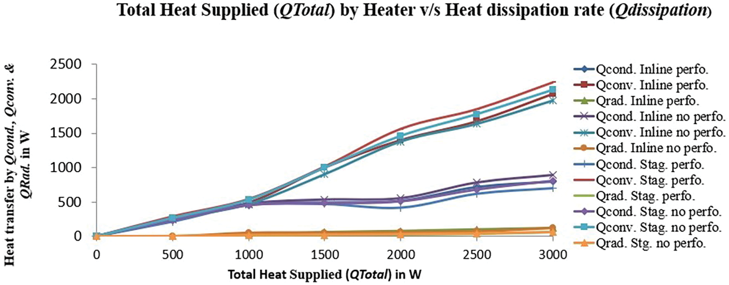
Figure 7: Energy balance analysis in four different symmetrical aerofoil pin-fin arrays
Fig. 8 depicts the efficiency of four categories of aerofoil-shaped pin-fins based on heat input supply. In terms of efficiency, the highest efficiency at 3000 W heat provided is up to 29.5% in the inline configuration with no holes on the aerofoil pin-fin. In the inline arrangement with holes on the aerofoil pin-fin, this efficiency was reduced by 5%. The staggered arrangements are randomly placed. As a result, compared to the inline arrangement, the staggered layout with no perforations in the aerofoil pin-fin reduced efficiency by 10%. There is an 8% decrease in efficiency when comparing no perforated staggered arrangement to a perforated staggered configuration. Furthermore, in comparison of without perforated inline arrangement with no perforated staggered and perforated staggered arrangement, there is a drop in efficiency from 8% to 10% and 13% to 15%, respectively.

Figure 8: Total heat supply to the symmetrical aerofoil pin-fin efficiency
The individual effectiveness of the symmetrical aerofoil pin-fin, on the other hand, has been evaluated based on the total heat supplied. The acquired values are plotted and are depicted in Fig. 9. Individual effectiveness ranges from 5.8 to 14.75 in the case of an inline configuration without any holes in the aerofoil pin-fin. There is a 2% increase in effectiveness for every 2% increase in total heat supply. For example, the effectiveness of an inline arrangement with perforations is 5% higher than the efficiency of a staggered configuration with perforations of the same category symmetrical aerofoil pin-fin. The effectiveness of the no perforated aerofoil pin-fin in inline arrangement is better than the same perforated inline aerofoil pin-fin. The effectiveness of inline arrangement with no perforations is 50% better effectiveness than inline arrangement with perforations on the aerofoil pin-fin. Whereas, the effectiveness of the staggered arrangement without perforation and with perforation is lower than inline arrangement. But from heat removal, pressure drop and material and natural resources saving point of view, staggered arrangement is better than inline arrangement.

Figure 9: Total heat supply to the effectiveness of symmetrical aerofoil pin-fin
5.4 Overall Effectiveness (εOvl. SAPFA)
The symmetrical aerofoil pin-fin array’s overall effectiveness has been assessed. It is used to assess the overall efficacy of the symmetrical aerofoil pin-fin array. Because determining the total efficacy of the symmetrical aerofoil pin-fin array is a more accurate assessment of the overall performance of the aerofoil pin-fin array than determining the performance of the individual symmetrical aerofoil pin-fin, the graph plot on total heat supply to the overall efficacy of the symmetrical aerofoil pin-fin array is shown in Fig. 10. The overall efficacy of the symmetrical aerofoil pin-fin array under inline configuration is clearly seen in this graph plot, outperforming the other three categories. There is a 25% difference in total effectiveness between the arrays with and without perforated inline arrangements. The overall effectiveness of perforated inline arrays with no perforated staggered and perforated staggered configurations is reduced by 5%.

Figure 10: Total heat supply to the overall effectiveness of symmetrical aerofoil pin-fin array
In terms of forced convection and experimental validation, the Nusselt number and friction factor have been considered. It should be mentioned that the Nusselt number is important in the forced convection experimental study, and the higher the Nusselt number value, the more effective the forced convection. Furthermore, the pressure drop is used to judge the arrangement and perforation factor on the symmetrical aerofoil pin-fin array for friction factor measurement and analysis. The empirical Dittus-Bolter and Blasius correlations were used to validate the experimental Nusselt number and friction factor.
The validation of heat transfer increase in terms of Nusselt number (Nu) subjected to variable turbulent Reynolds number (Re) is shown in Fig. 11. The experimental results of the forced convective heat dissipation enhancement rate number, Nu, were compared with the empirical correlation of Dittus-Bolter. The experimental values of Nu are found to be lower than the Dittus-Bolter correlation on Nu in this validation of experimental analysis and graph plot. The Dittus-Bolter correlation differs from experimental calculations by 2%. The computation uncertainty for both the experimental and correlation levels is 10%. It is obtained that the dimensionless number, Nu, of the forced convective heat dissipation rate indicator of the symmetrical aerofoil pin-fin array is greater in the absence of perforated inline arrangement than in other arrays. As a result, the heat dissipation rate of the no-perforated inline arrangement is greater than that of other arrays.

Figure 11: Validation of experimental Nusselt number with Dittus-Bolter correlation
The experimental friction factor (f) has been validated with the Blasius correlation. Experimental and empirical values are calculated and have been plotted in the graph. Fig. 12 represents the comparison and validation of experimental with empirical Blasius correlation with respect to Reynolds number (Re). Here, the experimental friction factor is slightly higher than Blasius correlation. In both cases, the friction factor is raised according to the increase in Reynolds number. Out of all the four symmetrical aerofoil pin-fin arrays, the friction factor in the perforated inline arrangement is high, and it reached a maximum of up to 0.093. The uncertainty of calculation is up to 5%. There is a difference between experimental and Blasius correlation is 15%. In the case of no perforated inline and staggered and perforated staggered arrangements, there is a 5% difference in the friction factor of the experimental with Blasius correlation. The overall experimental friction factor in no perforated inline and staggered and perforated staggered, the friction factor reached as 11%, 9% and 7%, respectively and their maximum value reached to 0.069, 0.057 and 0.048. In this experimental analysis, the friction factor has been successfully validated with Blasius correlation. The experimental friction factor is a bit higher than Blasius correlation by an average accuracy and uncertainty of calculation of 10%. This range of experimental friction factors is acceptable to suggest for mass production and replacement of other fins and pin-fins by a novel idea of symmetrical aerofoil pin-fins or fins without perforations and with perforations.

Figure 12: Validation of experimental friction factor with Blasius correlation
Perforated aerofoil shape pin-fin array leads to material saving and lightweight. It is an era of compact-size devices, so the incorporation of perforated aerofoil pin-fins is going to deliver an enhanced and instant rate of heat transfer from the device.
Hence, there is material and natural resource saving, lightweight, compact in size, improved heat dissipation, enhancement in safety from overheating and over-temperature development from the power delivering devices, and it takes care of human health from the usage of overheating and temperature devices. The ultimate goal is optimization, lightweight, compact size, diversion from usage of conventional extended surfaces to aerofoil pin-fins application, small scale and large scale production in domestic as well as industry to generate revenue to the individual and entrepreneur and to safeguard human life from endanger while using power delivering devices and machines.
An experimental analysis of a symmetrical aerofoil of different pin-fin arrays has been performed. Two types of pin fins are considered: inline and staggered with perforations and without perforations. The efficiency, efficacy, and total effectiveness of pin-fins have been calculated. In terms of overall efficacy, pin fin arrays achieve values varying between 1.8 to 14.7. The heat flux supply under forced convection varies between 500 to 3000 W/m2, and the air temperature varies between 50°C to 310°C. The forced convection heat transfer enhancement rate has been computed using dimensionless Nusselt number (Nu) and friction factor (f). The empirical correlation of Dittus-Bolter and Blasius correlations was used to validate the experimental heat dissipation enhancement factor requirements of Nusselt number and friction factor. Under tumultuous conditions, the Nu and f have been calculated. Reynolds number (Re) varied between 5000 to 50,000 for this experiment. The validation of the experiment with correlation has been successfully worked out. Experimentally calculated Nusselt number values have been validated with the Ditus-Bolter correlation. It has been observed that the experimental Nu values are lower than the said correlation due to the instrument’s precession, environmental conditions, materials, and heat loss during experiments. Henec’s experimental results prove that aerofoil pin-fin arrays can be used successfully for different applications like the electronics industry, heat exchangers and gas turbine blade cooling. The practical friction factor value is observed to be a bit higher than the Blasius correlation. From the experiment, it can be concluded that the model’s shape and size influence this friction factor. Due to that, the friction factor has been increased a bit more than the Blasius correlation. But it is within the acceptable range, and the maximum friction factor has occurred up to 0.093, below 1. Therefore, symmetrical aerofoil pin-fin arrays are fit for the service and performance to serve the heat dissipation rate enhancement.
Acknowledgement: We are deeply grateful to all those who contributed to the success of this research project.
Funding Statement: No funding is available for this work.
Author Contributions: The authors confirmed contribution to the paper as follows: Study concept and design, data collection analysis and interpretation: Mainak Bhaumik; Draft manuscript preparation: Anirban Sur; English, grammar check: Kavita Dhanawade.
Availability of Data and Materials: None.
Conflicts of Interest: The authors declare that they have no conflicts of interest to report regarding the present study.
References
1. Babak, L., Mehran Rajabi, Z., Bengt, S. (2023). The effect of short pin fin aspect ratio on thermal characteristics of intermittent impinging jet; An experimental and numerical study. Journal of the Taiwan Institute of Chemical Engineers, 148(10), 48–60. [Google Scholar]
2. Sur, A., Narkhede, S., Netke, A., Palheriya, H. (2023). Design and analysis of polymer heat sink for li-ion battery thermal management system. In: Maurya, A., Srivastava, A. K., Jha, P. K., Pandey, S. M. (Eds.Recent trends in mechanical engineering, pp. 323–329. Singapore: Springer. [Google Scholar]
3. Sur, A., Gulia, V. (2022). A comprehensive review on microchannel heat exchangers, heat sink, and polymer heat exchangers: Current state of the art. Frontiers in Heat and Mass Transfer, 18, 18–40. [Google Scholar]
4. Narkhede, S., Sur, A., Tiwari, R. (2023). The effects of topological configuration and geometric parameters on heat transfer and fluid flow characteristics of lattice-based heat sinks. Numerical Heat Transfer, Part A: Applications, 84(8), 1091–1105. [Google Scholar]
5. Bhandari, P., Rawat, S., Yogesh, K., Prajapati, D., Ranakoti, L. et al. (2023). Design modifications in micro pin fin configuration of microchannel heat sink for single phase liquid flow: A review. Journal of Energy Storage, 66, 1–16. [Google Scholar]
6. Gurav, B., Purohit, P., Tamkhade, K., Nalavade, P. (2023). Computational and analytical study on CPU heat sink cooling by single and double stack air-foil micro pin fins. Materials Today: Proceedings. https://doi.org/10.1016/j.matpr.2023.03.130 [Google Scholar] [CrossRef]
7. Zhang, S., Hua, J., Zhang, J., Gu, H., Zhang, X. et al. (2023). The simulation analysis on the influence of non-closed droplet structure on thermal/flow performance of pin fin heat sinks. International Journal of Thermal Sciences, 191(10), 83– 108. [Google Scholar]
8. Ludick, L., Craig, K. J., Valluri, P., Meyer, P. (2023). Influence of pin-fin patterns and geometry on the effectiveness of jet impingement boiling: A computational study. Applied Thermal Engineering, 229, 120626. [Google Scholar]
9. Rostami, S., Ahmadi, A., Raisi, A., Bayareh, M. (2023). Optimization of different pin-fins on heat transfer and pressure drop of a heat sink for antifreeze liquid case. Journal of the Taiwan Institute of Chemical Engineers, 148, 104811. [Google Scholar]
10. Ateş, A., Çelik, S., Yağcı, V., Malyemez, Ç., Parlak, M. et al. (2023). Flow boiling of dielectric fluid HFE–7000 in a minichannel with pin fin structured surfaces. Applied Thermal Engineering, 223, 120045. [Google Scholar]
11. Randa, I., Hatamleh, S., Alghamdi, M., Nidal, H., Meshari, A. et al. (2023). Cooling of a solar panel using nanofluid turbulent flow to improve energy and exergy efficiencies: Optimizing and simulating the effect of rectangular pin-fin height. Journal of the Taiwan Institute of Chemical Engineers, 48, 104857. [Google Scholar]
12. Hadipour, A., Mehran, Z. (2023). Heat transfer enhancement in array of impinging jets by a row of pin-fins on dead fluid zone. Journal of the Taiwan Institute of Chemical Engineers, 148, 104842. [Google Scholar]
13. Li, C., Li, X., Huang, H., Zheng, Y. (2023). Hydrothermal performance analysis of microchannel heat sink with embedded module with ribs and pin-fins. Applied Thermal Engineering, 225, 120167. [Google Scholar]
14. Chiu, H., Youh, M., Hsieh, R., Jang, J., Kumar, B. (2023). Numerical investigation on the temperature uniformity of micro-pin-fin heat sinks with variable density arrangement. Case Studies in Thermal Engineering, 44, 102853. [Google Scholar]
15. Wu, J., Li, N., Wu, Z. (2023). Experimental investigation of latent energy storage systems with the tree-pin-shaped fin. Applied Thermal Engineering, 227, 120370. https://doi.org/10.1016/j.applthermaleng.2023.120370 [Google Scholar] [CrossRef]
16. Markal, B., Beyzanur, K. (2023). Influence of downstream cross-sectional area ratio on flow boiling characteristics of expanding micro pin fin heat sinks. International Communications in Heat and Mass Transfer, 143, 106689. [Google Scholar]
17. Mellas, I., Municchi, M., Icardi, M. (2023). Dynamics of long bubbles propagating through cylindrical micro-pin fin arrays. International Journal of Multiphase Flow, 163, 104443. [Google Scholar]
18. Wang, L., Lu, X., He, M., Huang, C., Wang, L. (2023). Experimental study of convective heat transfer characteristics of ventilated passages formed by uniform diameter circular pin fins of disc brake. Case Studies in Thermal Engineering, 44, 102862. [Google Scholar]
19. Bhandari, P., Padalia, D., Ranakoti, L., Khargotra, R., Kovács, A. et al. (2023). Thermo-hydraulic investigation of open micro prism pin fin heat sink having varying prism sides. Alexandria Engineering Journal, 69, 457–468. [Google Scholar]
20. Ziad Saghir, M., Rahman, M., Bicer, Y. (2023). Investigation of channel materials toward better cooling lithium-ion batteries in the presence of nanofluid and pin-fins. International Journal of Thermo-Fluids, 18, 100349. [Google Scholar]
21. Wei, H., Zu, Y. (2023). Experimental and numerical studies on the enhanced heat transfer performance and the flow resistance characteristics of the double-wall cooling structure with jet impingement holes and pin fins. International Journal of Thermal Sciences, 186, 108109. [Google Scholar]
22. Nguyen, P., Maghsoudi, E., Scott, N., Beomjin, K. (2023). Shape optimization of pin fin array in a cooling channel using genetic algorithm and machine learning. International Journal of Heat and Mass Transfer, 202, 123769. [Google Scholar]
23. Ismail, O., Ali, A., Hassan, M., Gamea, O. (2023). Geometric optimization of pin fins for enhanced cooling in a microchannel heat sink. International Journal of Thermal Sciences, 190, 108321. [Google Scholar]
24. Khdair, A. (2023). Numerical simulation of heat transfer of two-phase flow in mini-channel heat sink and investigation the effect of pin-fin shape on flow maldistribution. Engineering Analysis with Boundary Elements, 150, 385–393. [Google Scholar]
25. Hua, J., Zhang, S., Zhang, J., Shao, Y., Gu, H. et al. (2023). The experimental analysis on the influence of non-closed droplet shape and location on thermal/flow performance of pin fin heat sinks. Applied Thermal Engineering, 224, 120132. [Google Scholar]
26. Dey, A., Ahmed, Z., Alam, R. (2022). Thermal and exergy analysis of pin-finned heatsinks for nanofluid cooled high concentrated photovoltaic thermal (HCPV/T) hybrid systems. Energy Conversion and Management, 16, 100324. [Google Scholar]
27. Ayşenur, A., Behnam, P., Yağcı, V., Malyemez, Ç., Parlak, A. et al. (2022). On the effect of elliptical pin fins, distribution pin fins, and tip clearance on the performance of heat sinks in flow boiling. Applied Thermal Engineering, 212, 118648. [Google Scholar]
28. Zhuang, X., Xie, L., Li, X., Yue, S., Wang, H. et al. (2023). Investigation on flow boiling of HFE-7100 in a microchannel with pin fin array. Applied Thermal Engineering, 225, 120180. [Google Scholar]
29. Chen, J., Yang, Z. (2023). Cause analysis on abnormal failure of copper-substrate pin fin heat sink for new energy vehicle. Engineering Failure Analysis, 143, 106947. [Google Scholar]
30. Yu, C., Zhu, X., Li, Z., Ma, Y., Yang, M. (2023). Optimization of elliptical pin-fin microchannel heat sink based on artificial neural network. International Journal of Heat and Mass Transfer, 205, 123928. [Google Scholar]
31. Liu, L., Yu, L., Yu, B., Liu, B., Wei, J. (2023). Flow boiling heat transfer enhancement via micro-pin-fins/Zn nanorods hierarchical surface. International Journal of Heat and Mass Transfer, 203, 123810. [Google Scholar]
32. Sung, G., Na, D., Yook, J. (2023). Enhancement of the cooling performance of a pin fin heat sink based on the chimney effect using aluminum tape. International Journal of Heat and Mass Transfer, 201, 123613. [Google Scholar]
33. Chang, W., Hsu, C. (2023). Comparative aerothermal performance of two rotating triple-pass channels with lateral flow exit roughened by skewed ribs and pin-fins with and without internal effusion. International Journal of Thermal Sciences, 188, 108243. [Google Scholar]
34. Shahsavar, A., Heidarian, M., Yıldız, C., Arıcı, M. (2023). Effect of open-ring pin fin arrangement on the thermal performance and entropy generation of a heat sink cooled by biologically synthesized silver-water nanofluid. Engineering Analysis with Boundary Elements, 150, 599–611. [Google Scholar]
35. Alkhazaleh, A., Alnaimat, F., Selim, M., Mathew, B. (2023). Liquid cooling of microelectronic chips using MEMS heat sink: Thermohydraulic characteristics of wavy microchannels with pin-fins. International Journal of Thermo-Fluids, 18, 100313. [Google Scholar]
36. Hasani, H., Freegah, B. (2022). Influence of secondary flow angle and pin fin on hydro-thermal evaluation of double outlet serpentine mini-channel heat sink. Results in Engineering, 16, 100670. [Google Scholar]
37. Bhaumik, M., Dhanawde, K., Sur, A. (2023). A numerical model analysis on perforated aero-foil shaped pin fin arrays in heat dissipation enhancement, pressure drop and optimization. Materials Today: Proceedings. https://doi.org/10.1016/j.matpr.2023.05.491 [Google Scholar] [CrossRef]
Cite This Article
 Copyright © 2023 The Author(s). Published by Tech Science Press.
This work is licensed under a Creative Commons Attribution 4.0 International License , which permits unrestricted use, distribution, and reproduction in any medium, provided the original work is properly cited.
 Downloads
 Citation Tools