
 Submit a Paper
 Propose a Special lssue
 Open Access
ARTICLE
Lubrication of Asymmetric Rollers Using Roelands Viscosity–Pressure-Temperature Relationship
1 Department of Engineering Mathematics, Koneru Lakshmaiah Education Foundation, Andhra Pradesh, Guntur, 522502, India
2 Department of Mathematics, Kanchi Mamunivar Government Institute for Post Graduate Studies and Research,
Puducherry, 605008, India
* Corresponding Author: Venkata Subrahmanyam Sajja. Email:
Frontiers in Heat and Mass Transfer 2023, 21, 385-405. https://doi.org/10.32604/fhmt.2023.042544
Received 03 June 2023; Accepted 28 July 2023; Issue published 30 November 2023
 View Full Text
 Download PDF
Abstract
An attempt is made to analyse some lubrication characteristics of rigid cylindrical asymmetric rollers under adiabatic and isothermal boundaries with rolling and sliding motion lubricated by a non-Newtonian incompressible Bingham plastic fluid under the behaviour of line contact. Here the lower surface is considered to move quicker than that of the upper surface; and the Roelands viscosity model is considered and assumed to depend upon the fluid pressure and the mean film temperature. The governing equations for fluid flow such as equations of motion with continuity and the momentum energy equation are solved using Runge-Kutta forth order and MATLAB is employed to solve these equations. Through graphs and tables for Newtonian and non-Newtonian fluids, the several crucial bearing characteristics including velocity, pressure, viscosity, mean temperature, load and traction are examined and a significant change is observed among them. The findings presented here are qualitatively consistent with the existing literature.Keywords
Nomenclature
| h | Film thickness |
| h0 | Minimum film thickness |
| p | Hydrodynamic pressure |
| TFh | Traction force |
| u | Fluid velocity in x-direction |
| U1, U2 | Velocities of the surfaces |
| v | Fluid velocity in y-direction |
| x1 | Point of maximum pressure |
| x2 | Point of cavitation |
| α | Pressure coefficient |
Modelling and study of fluid flow in thin gaps play a key role in classical lubrication theory. Examples of thin gaps where fluid can flow include the space between a bearing’s ball and raceway, a seal’s contacting surfaces, the space between an eye and a contact lens, and the spaces in our joints [1]. Lubrication modeling is essential for predicting the lubricant state, friction coefficient, and failure risk under different lubrication regimes. The Reynolds equation can precisely describe the full film lubrication for a smooth surface [2]. Hydrodynamic lubrication is a technique for lowering wear and friction on fluid-rubbing surfaces, and its purpose is usually to append a suitable fluid with the aim of penetrating the contact area among the moving surfaces and forming a thin film of fluid. By producing a fluid layer between the surfaces that are rubbing, lubricant isolates the contacting mating surfaces. Metal-to-metal contact is decreased by the fluid film [3]. The main purpose of developing lubrication theory is to determine oil pressure distributions that help researchers improve the mechanical design of bearings [4].
Bearings are constantly subjected to incredibly high loads, top speeds, and severe sliding conditions. High-pressure aging occurs within the fluid film due to the impact of high stress on intensive contact processing. In the pressure-peak regime, the material properties of the fluid, especially its viscosity, are not constant but change continuously with the pressure and temperature [5]. They studied a roller bearing problem lubricated by an incompressible non-Newtonian power-law fluid for an extremely loaded rigid system, including temperature effects. A noticeable change in pressure and mean temperature was observed. Further, Sajja et al. [6] investigated some lubrication characteristics of non-symmetric rollers lubricated by incompressible power-law fluids, including thermal effects, and notable changes were observed in temperature and pressure.
The most crucial characteristic of a lubricant is its viscosity, which is measured as the amount of resistance to fluid flow. When the viscosity is excessively high, friction losses and operating temperature increase along with lubricant thickness. A lubricant will be thinner and have insufficient load carrying capacity if its viscosity is too low. It can be difficult to choose the lubricant’s ideal viscosity when all of these things are taken into account [7]. Since viscosity decreases as lubricant temperature rises, it is essential to increase the lubricant viscosity index by using high-molecular weight polymers in order to stop temperature-related viscosity changes [8]. For heavily loaded rigid cylindrical line contact with cavitation, Prasad et al. [5] investigated thermal hydrodynamic lubrication by incompressible power law lubricants. The influence of rolling/sliding ratio on pressure, temperature, viscosity, load and tractions are investigated using the rolling ratio and the assumption that the lubricant’s consistency/viscosity varies with pressure and the mean film temperature under isothermal boundaries. Prasad et al. [9] analyzed a hydrodynamic lubrication problem considering heat energy equation with convection and application of journal bearing, assuming the viscosity as a function of pressure and mean temperature. With increasing power density and the use of lower viscosities, the operating conditions of mechanical elements tend to be more severe, requiring an understanding of the effects of surface roughness and surface irregularities on lubricating performance, durability increases oil efficiency [10].
Many fluids used in the latest engineering exhibit rheological efforts. Hence investigators are particularly interested in the dynamics of non-Newtonian fluids, which are most useful in industry. The impacts of both cavitation and non-Newtonian behavior are extensively studied using computational fluid dynamics and fluid-structure interaction methods based on real-world physical models [11]. Because of its simplicity and capacity to calculate pressure loss in turbulent flow, the Bingham plastic model is commonly used to represent the flow properties of many types of mud. The most popular rheological model utilized in the drilling business is the Bingham plastic fluid [12]. Using a model where the material behaves as a solid when the shear stress magnitude is smaller than a specific yield stress, the flow of a Bingham plastic fluid is described. When the internal stress of the material is greater than the yield stress, the material acts like a liquid [13]. The non-Newtonian Bingham plastic fluid flow characteristics are used to show the passage of fluids, specifically fluids, for a long time and the development of melts and slurries in molds [14]. Additionally, they pointed out a model of the behavior of Bingham-like fluids that exhibited yield stress. Examining grease speculatively using the Bingham model and returning to Milne [15], he studied basic 1-D plain bearings and plain bearings and concluded that a rigid “core” might be attached to both surfaces. To determine if the performance of the grease in the ball-on-disk test is typical of real bearings. Kanazawa et al. [16] evaluated the frictional behavior of several grease formulations in rolling bearings and single-contact ball-on-disc rigs. The study used specially formulated greases with systematically different formulations in order to isolate the impact of base oil viscosity and thickening on grease frictional performance. According to the modified Reynolds equation for non-Newtonian fluid and its numerical solution by the finite difference method, Kouider et al. [17] presented the impact of non-Newtonian fluid behavior on the hydrodynamic properties of journal bearings. We present the fluctuations of some hydrodynamic properties, including pressure, load, and flow rate. They also came to the conclusion that the L/D ratio, eccentricity ratio, and type of lubricant all have an impact on the hydrodynamic properties of the journal bearing.
Not much work has been carried out by the researchers from this field taking into account asymmetric roller bearings with viscosity as a function of pressure and temperature. Hence in the present work, the attention has been focused on analyzing some non-Newtonian lubrication properties of non-symmetric roller bearings lubricated by an in-compressible Bingham plastic fluid under cavitation. The effects of the rolling and sliding behavior on pressure, load, and traction are investigated using rolling ratios. Roelands viscosity is here considered that takes into account the fluid pressure and the mean film temperature.
The system is described in this study in such a way that both moving surfaces have the same radius but different speeds. The upper surface is made to move at more speed than that of the lower surface. Fig. 1 depicts the entire flow configuration.
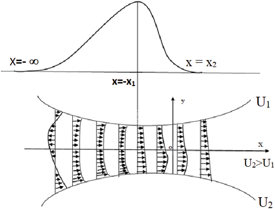
Figure 1: Lubrication of asymmetric rollers
According to common presumptions [18], the following equations, such as continuity and momentum, which regulate the flow of incompressible fluids, are taken into consideration:
where “p” and “τ” stand for the lubricant pressure and shear stress, respectively. According to Sasaki et al. [19], the constitutive relation for Bingham plastic fluid can be considered as follows:
where ‘
where
R denotes the radius of the equivalent cylinder.
The following boundary conditions are assumed for both the upper and lowers surfaces in this problem:
where
Applying the above boundary conditions, Eq. (2) is solved to get the fluid velocity expression as below:
By integrating the velocity in the space between the surfaces as shown below, it is possible to determine the “volume flux” or “Q” for the flow of fluid:
At the point of maximum pressure, the volume flux can be taken as
where
Pressure Reynolds equation can be obtained by solving the Eqs. (1) & (2) using the boundary conditions as given below:
The following is the dimensionless scheme for this problem:
Making use of the above dimensionless technique, the expression for velocity and pressure Reynolds equation are obtained in dimensionless form as follows:
Applying the outlet condition of Eq. (9) to Eq. (15) immediately gives
The heat flow equation [6] for the problem with usual assumptions may be considered as
The boundary conditions are
The temperature of the lubricant can be obtained by integration of Eq. (15) gives
The lubricant mean temperature ‘Tm’ may be defined as
Now the dimensionless form of temperature and mean temperatures are obtained as follows:
where
2.6 Load and Traction [6]
Load capacity is one of the important characteristics since it produces an accurate evaluation of the bearings’ effectiveness. Therefore, the x-component of the load Wx per unit length of the cylinder is given by integrating the pressure over the film thickness as follows:
The load
Similarly, the normal load Wy can be obtained as
The dimensionless normal load
By integrating the shear stress ‘τ’ throughout the full length, it is also possible to determine the traction forces TFh at the surfaces.
Tractions in the dimensionless form are
3.1 Methodology of Numerical Solution
The Reynolds and the energy equations are coupled through
First of all, an initial value of
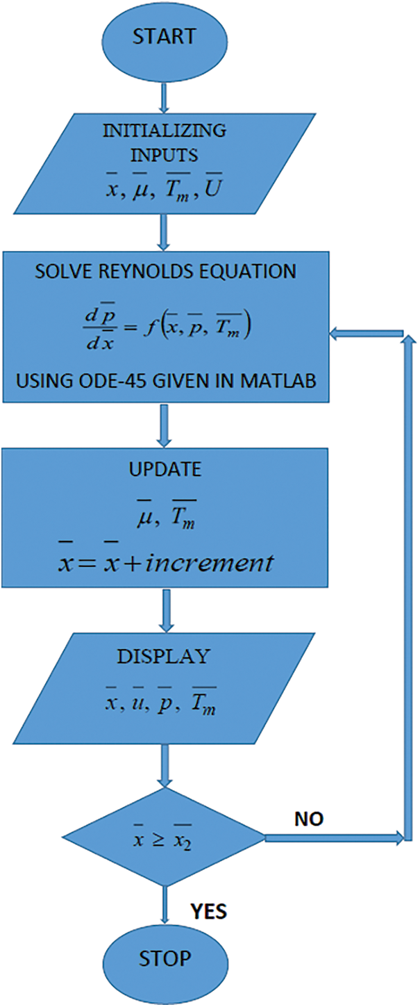
Figure 2: Flow chart representing numerical process
The following values are used in this problem for numerical computations:
Figs. 3–5 display the velocity of the fluid for the regions: before-after and at the pressure-peak point, respectively. The curves in the first two graphs resemble parabolas with upward and downward pointing vertices in the areas before and after the maximum pressure point. A backflow is present close to the inlet, as indicated by the vertices below the line
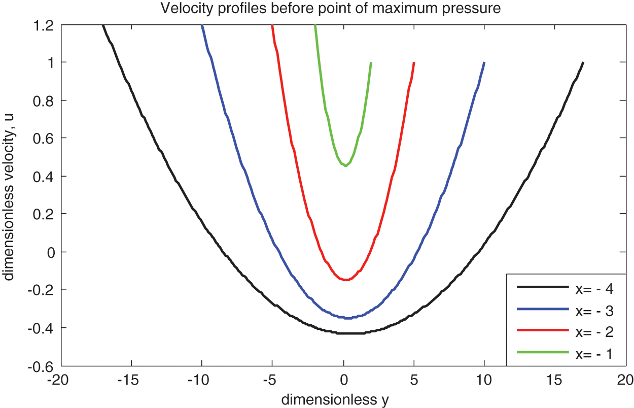
Figure 3: Velocity at inlet region
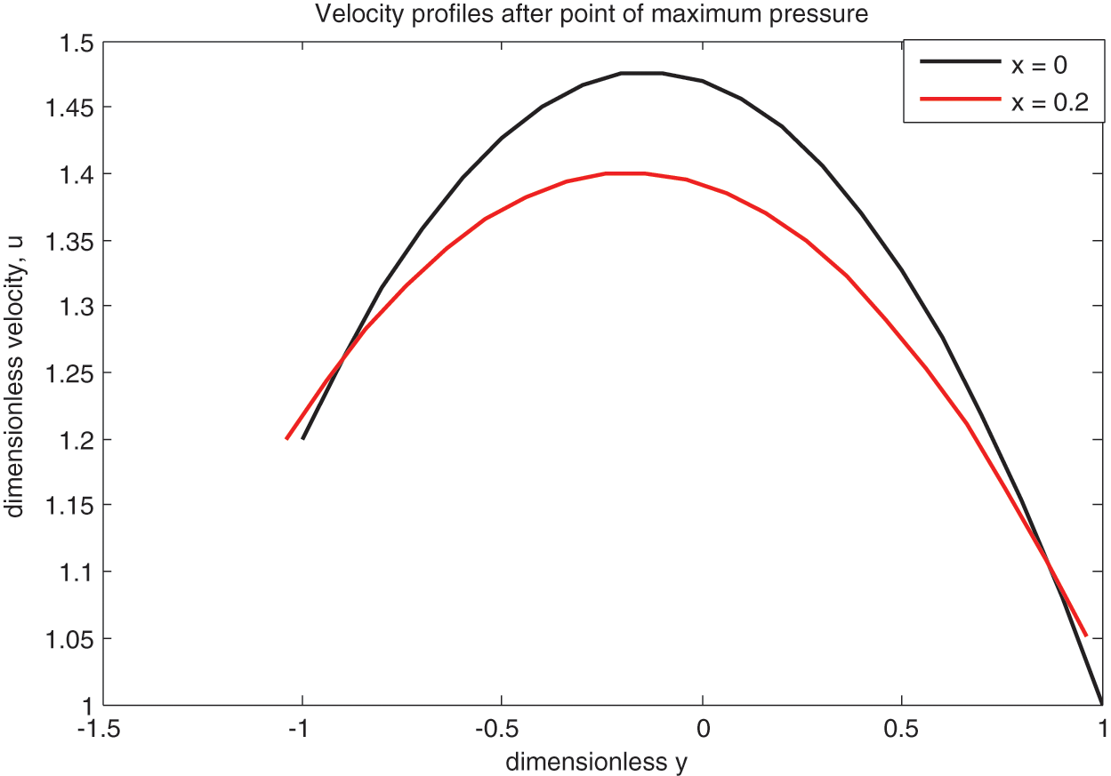
Figure 4: Velocity at outlet region
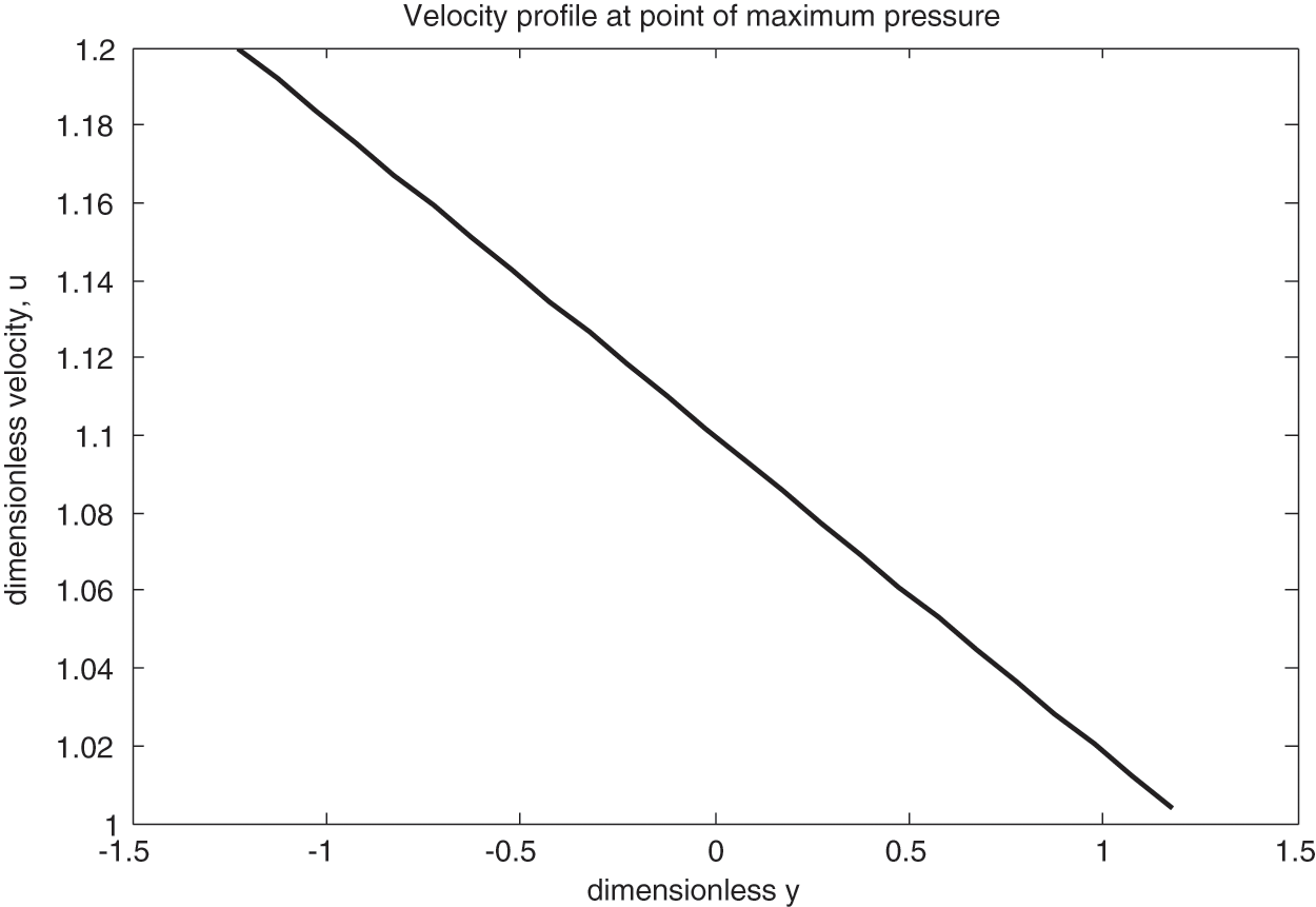
Figure 5: Velocity at pressure peak
The pressure distributions are qualitatively estimated and shown in Figs. 6–8. Figs. 6 and 7 show that pressure rises with rolling ratio Ū for both Newtonian and non-Newtonian fluids. This shows that sliding cases experience more hydrodynamic pressure than that of pure rolling. Prasad et al. [5], Prasad et al. [23], Sajja et al. [6], Prasad et al. [24] and Revathi et al. [25] all reported similar kinds of behavior. Fig. 8 shows the lubricating pressure for the sliding case at various values of yield stress parameter
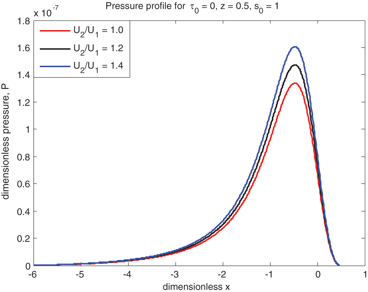
Figure 6: Newtonian pressure vs.
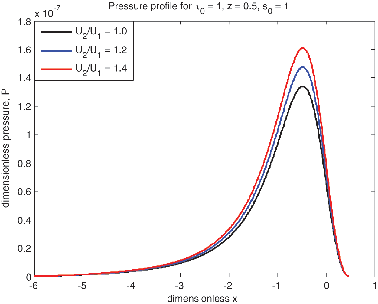
Figure 7: Non-Newtonian pressure vs.
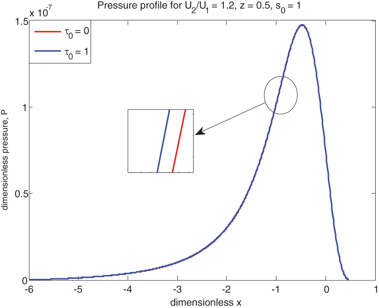
Figure 8: Pressure comparison between Newtonian and non-Newtonian
Further, the cavitation points where the pressure and pressure gradient becomes zero are calculated numerically presented in Table 1 for both Newtonian and non-Newtonian cases. The cavitation points are increasing as rolling ratio Ū increases for both ‘Newtonian and non-Newtonian’ cases.
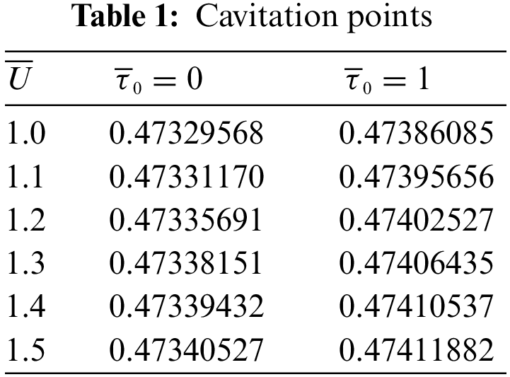
The lubricant ‘viscosity’
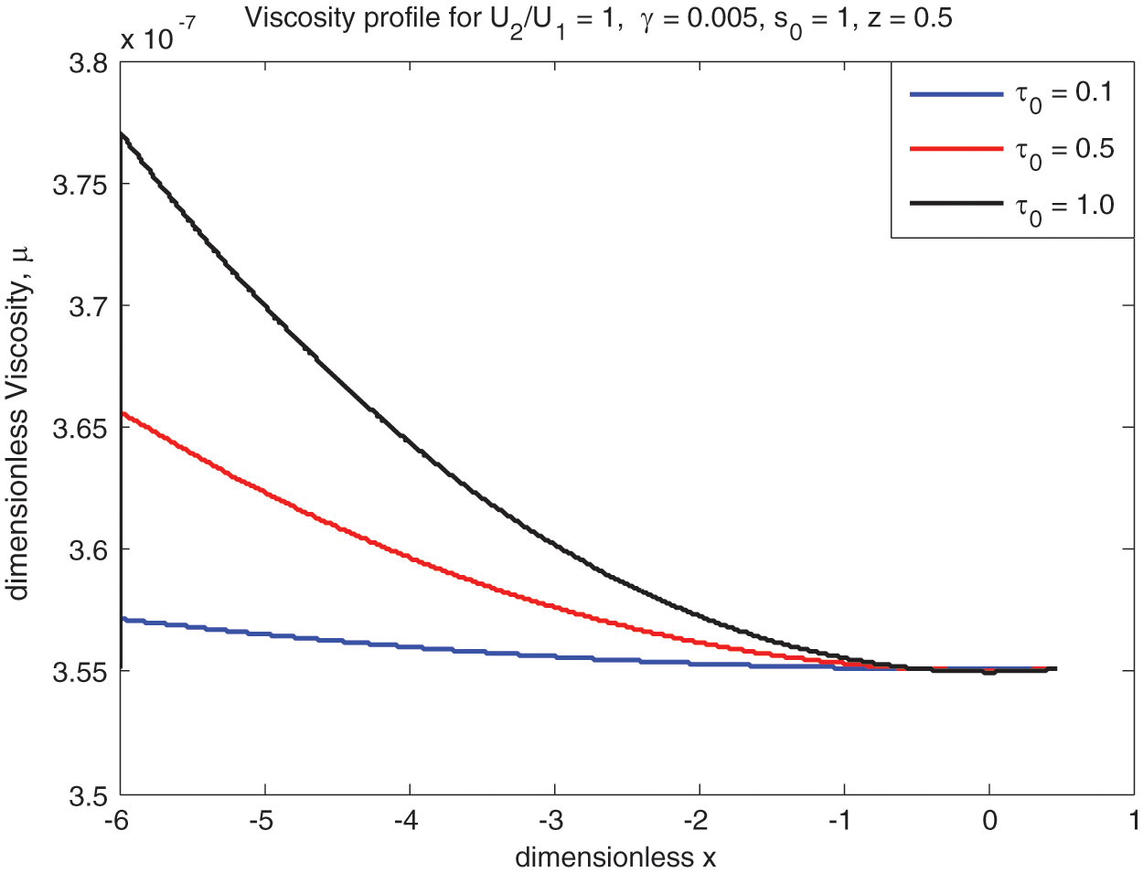
Figure 9: Effect of viscosity along x-axis
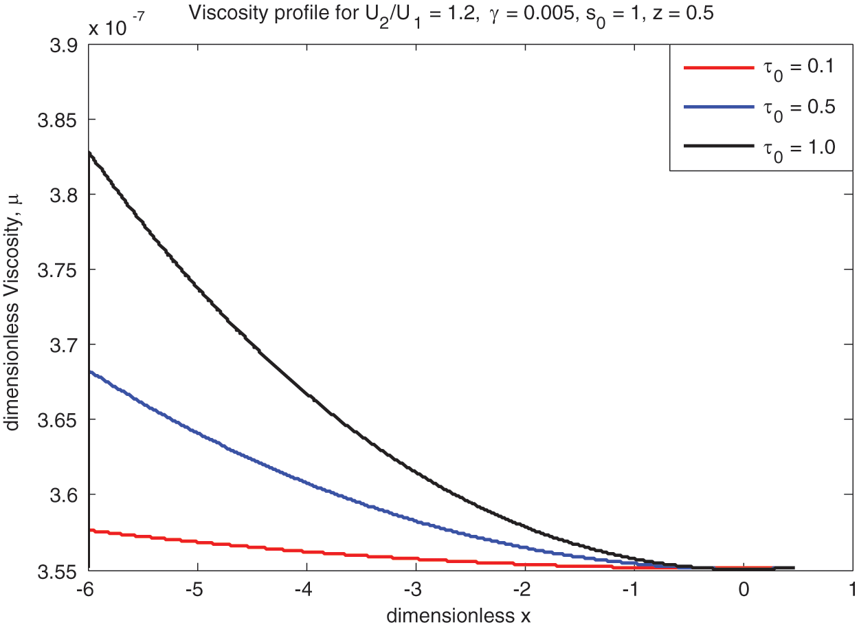
Figure 10: Sliding viscosity vs.
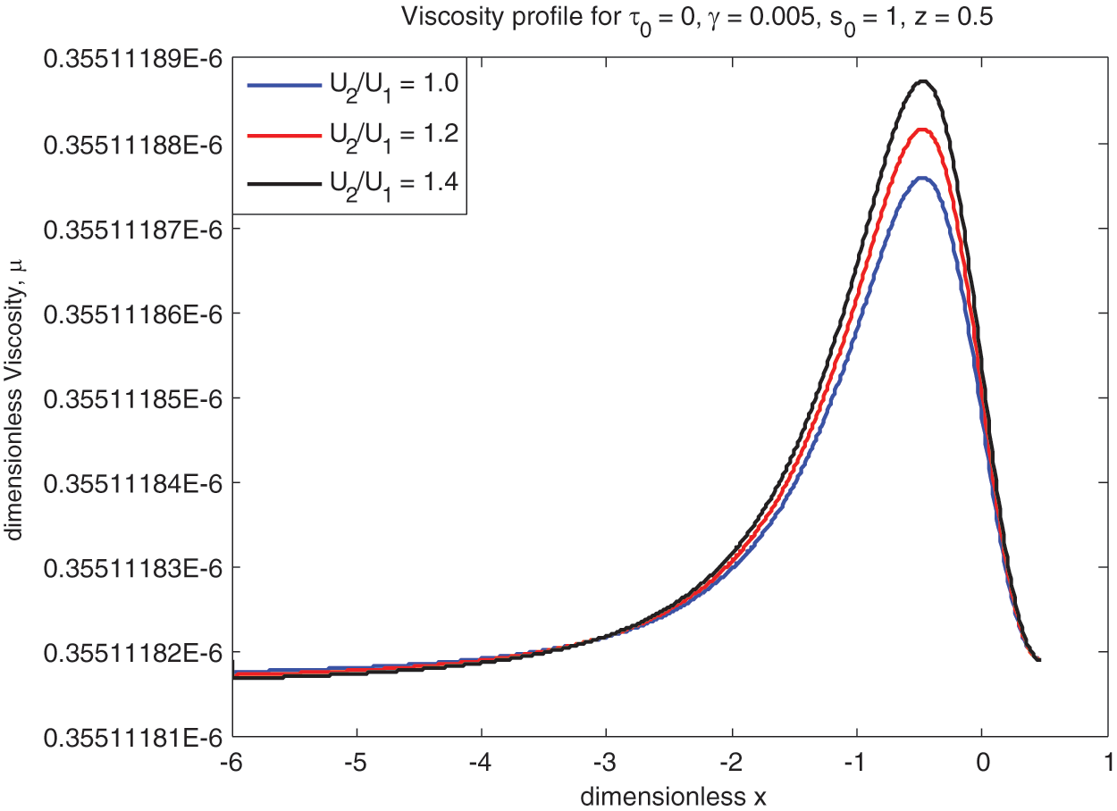
Figure 11: Newtonian viscosity vs.
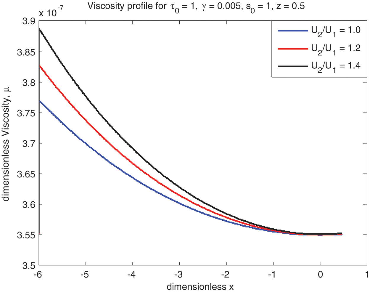
Figure 12: Non-Newtonian viscosity vs.

Figure 13: Sliding viscosity vs.
3.5 Mean Temperature (
The lubricant mean temperature
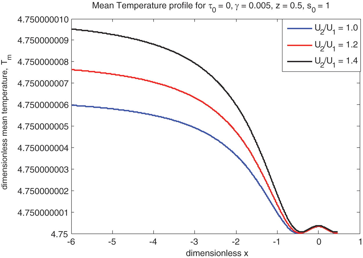
Figure 14: Newtonian mean temperature vs.
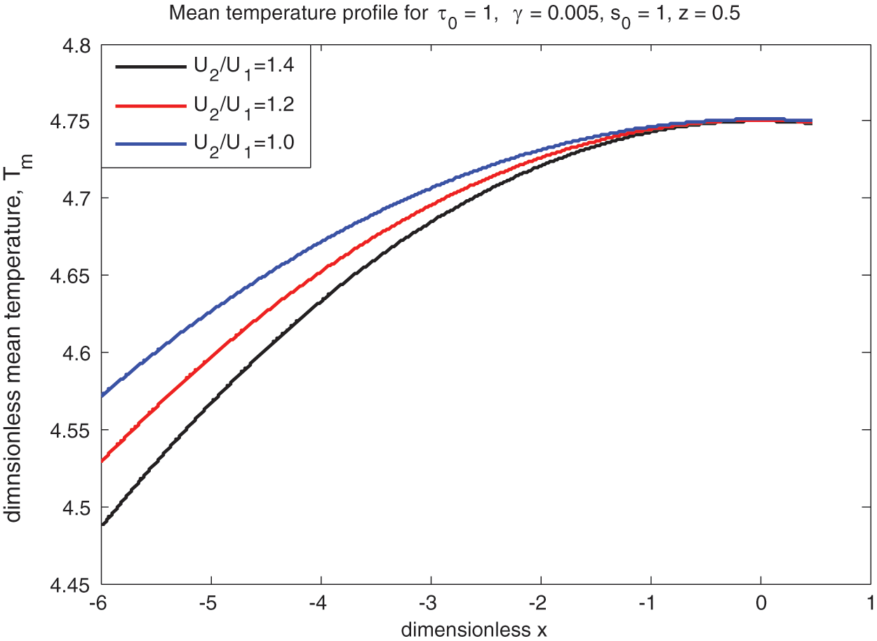
Figure 15: Non-Newtonian mean temperature vs.
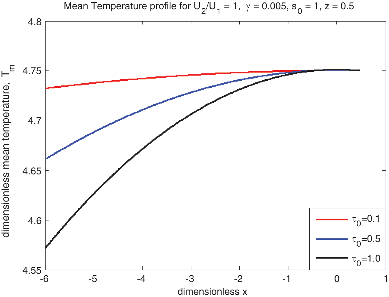
Figure 16: Mean temperature profile
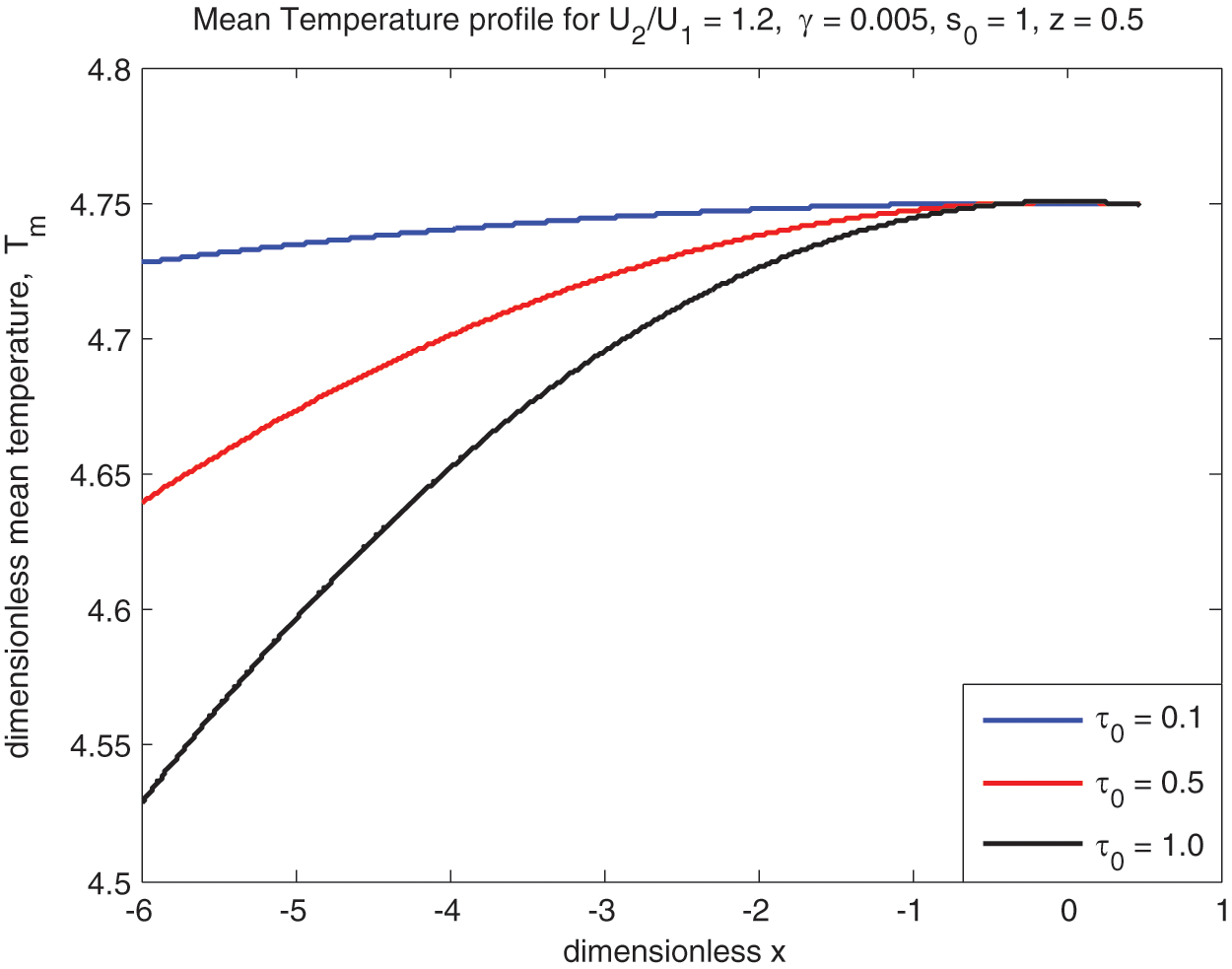
Figure 17: Sliding mean temperature vs.
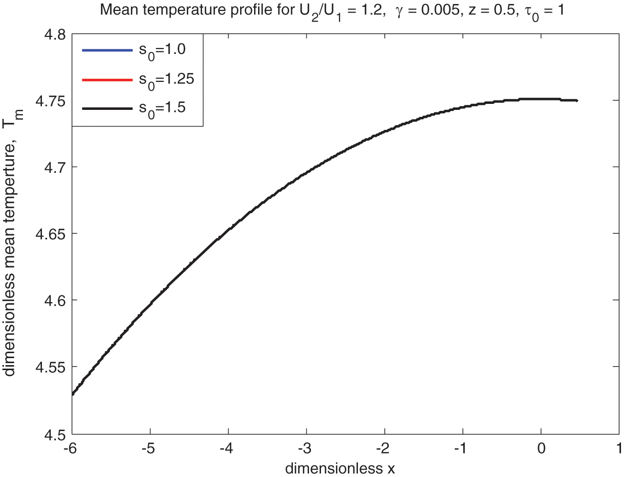
Figure 18: Sliding mean temperature vs.
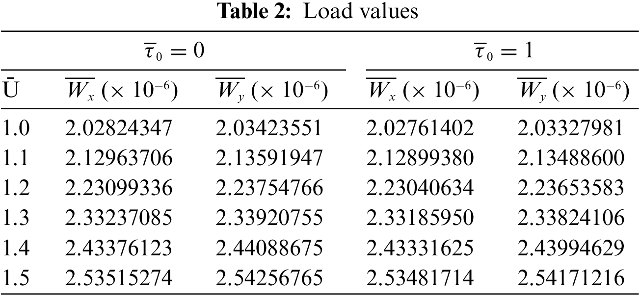
The non-dimensional load in both the x and y directions are numerically determined for various values of Ū and
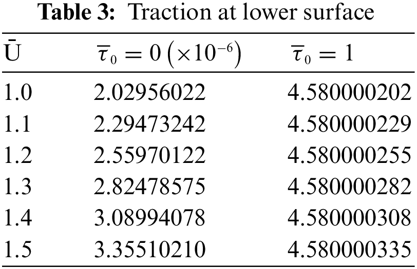
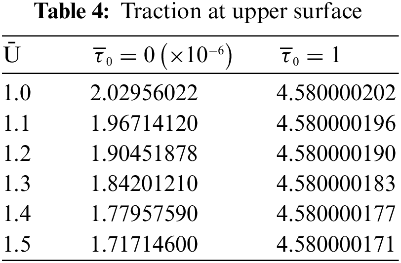
Traction forces are presented in Tables 3–4 for both the surfaces for various values of
A very useful non-Newtonian Bingham plastic fluid model is used to explore the lubricating properties of rolling/sliding rigid line contact of asymmetric rollers problem. Roelands viscosity model is here employed to study such system for various values of the sliding parameter Ū and yield stress parameter
• The velocity of the lubricant is found to be free from
• Lubricant velocity decreases linearly at the pressure-peak point.
• The pressure increases with Ū and
• Points of pressure-peak shift towards the center line of contact as Ū increases.
• Cavitation points move towards right as rolling ratio Ū increases.
• Viscosity increases with rolling ratio Ū for both ‘Newtonian and non-Newtonian’ fluids. The same kind of trend exists for the yield stress as well.
• The temperature
• Temperature
• Load increases with rolling ratio Ū. However, the traction forces have no such fixed trend. More traction force occur due to more speed of the surfaces and the yield stress also exhibits the same pattern.
Acknowledgement: The investigators remain profusely grateful to Koneru Lakshmaiah Education Foundation, Guntur, India for extending support and assistance with required permissions during this research study at the Department of Mathematics and to Sir C R Reddy College of Engineering, Eluru for necessary permissions and extending facilities for the work.
Funding Statement: The authors received no specific funding for this study.
Author Contributions: Swetha Lanka: Writing–original draft, Methodology, Data curation, Visualization, Project administration. Venkata Subrahmanyam Sajja: Supervision, Conceptualization, Validation, Software. Dhaneshwar Prasad: Visualization, Writing review & editing, Conceptualization.
Availability of Data and Materials: Data will be made available on request.
Conflicts of Interest: The authors declare that they have no conflicts of interest to report regarding the present study.
References
1. Almqvist, A., Burtseva, E., Pérez-Ráfols, F., Wall, P. (2019). New insights on lubrication theory for compressible fluids. International Journal of Engineering Science, 145, 103170. https://doi.org/10.1016/j.ijengsci.2019.103170 [Google Scholar] [CrossRef]
2. Wu, M. J., Han, X., Tao, Y. R., Pei, J. X. (2022). An average flow model considering non-Newtonian characteristics with application to grease behavior. Journal of Tribology, 144, 101802-1–101802-12. https://doi.org/10.1115/1.4054508 [Google Scholar] [CrossRef]
3. Srivyas, P. D., Charoo, M. S. (2018). A review on tribological characterization of lubricants with nano additives for automotive applications. Tribology Industry, 40(4), 594–623. https://doi.org/10.24874/ti.2018.40.04.08 [Google Scholar] [CrossRef]
4. Abbaspur, A., Norouzi, M., Akbarzadeh, P., Vaziri, S. A. (2021). Analysis of nonlinear viscoelastic lubrication using Giesekus constitutive equation. Proceedings of the Institution of Mechanical Engineers, Part J: Journal of Engineering Tribology, 235(6), 1124–1138. https://doi.org/10.1177/1350650120944280 [Google Scholar] [CrossRef]
5. Prasad, D., Subrahmanyam, S. V., Panda, S. S. (2012). Thermal effects in hydrodynamic lubrication of asymmetric rollers using Runge-Kutta Fehlberg method. International Journal of Engineering Science & Advanced Technology, 2(3), 422–437. [Google Scholar]
6. Sajja, V. S., Prasad, D. (2015). Characterization of lubrication of asymmetric rollers including thermal effects. Industrial Lubrication and Tribology, 67(3), 246–255. https://doi.org/10.1108/ILT-04-2013-0048 [Google Scholar] [CrossRef]
7. Hussain, Md M., Pratap, A. P., Gaval, V. R. (2021). Study of vegetable oil based bio lubricants and its hydrodynamic journal bearing application: A review. Tribology in Industry, 43(4), 511–523. https://doi.org/10.24874/ti.979.10.20.02 [Google Scholar] [CrossRef]
8. Azeez, S., Bertola, V. (2021). Lubrication of journal bearings by shear thinning lubricants using different constitutive models. Proceedings of the Institution of Mechanical Engineers, Part J: Journal of Engineering Tribology, 235(6), 1203–1210. https://doi.org/10.1177/1350650120950521 [Google Scholar] [CrossRef]
9. Prasad, D., Panda, S. S., Sajja, V. S. (2018). Journal bearing lubrication of power law fluid with consistency variation including convection. In: Singh, M., Kushvah, B., Seth, G., Prakash, J. (Eds.Applications of fluid dynamics. Singapore: Springer. https://doi.org/10.1007/978-981-10-5329-0_20 [Google Scholar] [CrossRef]
10. Hultqvist, T., Vrcek, A., Johannesson, T., Marklund, P., Larsson, R. (2021). Transient plasto-elastohydrodynamic lubrication concerning surface features with application to split roller bearings. Proceedings of the Institution of Mechanical Engineers, Part J: Journal of Engineering Tribology, 235(2), 453–467. https://doi.org/10.1177/1350650120927566 [Google Scholar] [CrossRef]
11. Pratomo, A. W., Muhammad, M., Tauviqirrahman Jamari, J., Bayuseno, A. P. (2019). Analysis of non-Newtonian lubricated textured contact for mixed slip/no-slip configuration considering cavitation. Journal of Physics Conference Series, 1217, 012014.https://doi.org/10.1088/1742-6596/1217/1/012014 [Google Scholar] [CrossRef]
12. Rehm, B., Haghshenas, A., Paknejad, A. S., Al-Yami, A., Hughes, J. (2013). Underbalanced drilling: Limits and extremes. Elsevier. https://doi.org/10.1016/C2013-0-15513-4 [Google Scholar] [CrossRef]
13. Lampaert, S. G., van Ostayen, R. A. (2020). Lubrication theory for Bingham plastics. Tribology International, 147(4), 106160. https://doi.org/10.1016/j.triboint.2020.106160 [Google Scholar] [CrossRef]
14. Dorier, C., Tichy, J. (1992). Behavior of Bingham-like viscous fluid in lubrication flow. Journal of Non Newtonian Fluid Mechanics, 45(3), 291–310. https://doi.org/10.1016/0377-0257(92)80065-6 [Google Scholar] [CrossRef]
15. Milne, A. A. (1954). A theory of rheodynamic lubrication. Kolloid-Zeitschrift, 139, 96–101. https://doi.org/10.1007/BF01502330 [Google Scholar] [CrossRef]
16. Kanazawa, Y., de Laurentis, N., Kadiric, A. (2020). Studies of friction in grease-lubricated rolling bearings using ball-on-disc and full bearing tests. Tribology Transactions, 63(1), 77–89. https://doi.org/10.1080/10402004.2019.1662147 [Google Scholar] [CrossRef]
17. Kouidera, M., Djallel, Z., Abdelkader, Y., Sahraoui, K. (2021). Mathematical modeling of journal bearing lubricated with non-Newtonian fluid. Tribology in Industry, 43(4), 615–623. [Google Scholar]
18. Prasad, D., Singh, P. (1987). Thermal and squeezing effects in non-Newtonian fluid film lubrication of rollers. Wear, 119, 175–190. https://doi.org/10.1016/0043-1648(87)90107-4 [Google Scholar] [CrossRef]
19. Sasaki, T., Mori, H., Okino, N. (1962). Fluid lubrication theory of roller bearing. Journal of Basic Engineering, 84(1), 166–174. https://doi.org/10.1115/1.3657240 [Google Scholar] [CrossRef]
20. Lubricant viscosity (2021). Tribonet about Tribology website. https://www.tribonet.org/wiki/lubricantviscosity/?utm_source=tribonet+community%26;utm_campaign=f923444c2cEMAIL_CAMPAIGN_2017_12_03_COPY_02%26;utm_medium=email%26;utm_term=0_79f2001725-f923444c2c-215516733 [Google Scholar]
21. Prasad, D., Sajja, V. S. (2016a). Non-Newtonian lubrication of asymmetric rollers with thermal and inertia effects. Tribology Transactions, 59(5), 818–830. https://doi.org/10.1080/10402004.2015.1107927 [Google Scholar] [CrossRef]
22. Prasad, D., Shukla, J. B., Singh, P., Sinha, P., Chhabra, R. P. (1991). Thermal effects in lubrication of asymmetrical rollers. Tribology International, 24(4), 239–246. https://doi.org/10.1016/0301-679X(91)90050-J [Google Scholar] [CrossRef]
23. Prasad, D., Subrahmanyam, S. V. (2014). Thermo hydrodynamic lubrication characteristics of power law fluids in rolling/sliding line contact. In: Patel, H., Deheri, G., Patel, H., Mehta, S. (Eds.Proceedings of International Conference on Advances in Tribology and Engineering Systems, New Delhi: Springer. https://doi.org/10.1007/978-81-322-1656-8_11 [Google Scholar] [CrossRef]
24. Prasad, D., Subrahmanyam, S. V. (2016b). Thermal effects in non-Newtonian lubrication of asymmetric rollers under adiabatic and isothermal boundaries. International Journal of Chemical Sciences, 14(3), 1641–1656. [Google Scholar]
25. Revathi, G., Sajja, V. S., Prasad, D. (2019). Thermal effects in power-law fluid film lubrication of rolling/sliding line contact. International Journal of Innovative Technology and Exploring Engineering, 8(9), 277–283. https://doi.org/10.35940/ijitee.H7195.078919 [Google Scholar] [CrossRef]
26. Gadamsetty, R., Sajja, V. S., Lanka, S., Prasad, D. (2020). Thermohydrodynamic lubrication of asymmetric rollers by Bingham plastic fluid. Solid State Technology, 63(5), 6165–6181. [Google Scholar]
27. Lee, R. T., Yang, K. T., Chiou, Y. C., Lin, Y. T. (2021). Thermal effect on a mixture lubrication with oil-in-water emulsions in EHL contacts. Tribology Transactions, 64(2), 202–213. https://doi.org/10.1080/10402004.2020.1820122 [Google Scholar] [CrossRef]
28. Lanka, S., Sajja, V. S., Prasad, D. (2023). Lubrication of asymmetric rollers considering viscosity as function of mean temperature. International Journal of Applied Mechanical Engineering, 28(2), 49–63. https://doi.org/10.59441/ijame/168331 [Google Scholar] [CrossRef]
29. Prasad, D., Singh, P., Sinha, P. (1988). Non-uniform temperature in non-Newtonian compressible fluid film lubrication of rollers. Journal of Tribology, 110, 653–658. https://doi.org/10.1115/1.3261708 [Google Scholar] [CrossRef]
30. Lanka, S., Sajja, V. S., Prasad, D. (2023). Thermal effects in lubrication of asymmetric rollers using roelands viscosity-pressure equation including convection. International Journal of Heat and Technology, 41(3), 701–708. https://doi.org/10.18280/ijht.410324 [Google Scholar] [CrossRef]
Cite This Article
 Copyright © 2023 The Author(s). Published by Tech Science Press.
This work is licensed under a Creative Commons Attribution 4.0 International License , which permits unrestricted use, distribution, and reproduction in any medium, provided the original work is properly cited.
 Downloads
 Citation Tools