
 Submit a Paper
 Propose a Special lssue
 Open Access
ARTICLE
The Numerical Simulation of Nanofluid Flow in Complex Channels with Flexible Wall
Mechanical Engineering Department, Babylon University, Hillah City, Iraq
* Corresponding Author: Amal A. Harbood. Email:
Frontiers in Heat and Mass Transfer 2023, 21, 293-315. https://doi.org/10.32604/fhmt.2023.01518
Received 26 February 2023; Accepted 16 May 2023; Issue published 30 November 2023
 View Full Text
 Download PDF
Abstract
The current work seeks to examine numerical heat transfer by using a complicated channel with a trapezoid shape hanging in the channel. This channel demonstrates two-dimensional laminar flow, forced convective flow, and incompressible flow. To explore the behavior of heat transfer in complex channels, several parameters, such as the constant Prandtl number (Pr = 6.9), volume fraction (ϕ) equal to (0.02 to 0.04), Cauchy number (Ca) equal to (10−4 to 10−8), and Reynolds number equal to (60 to 160) were utilized. At the complex channel, different elastic walls are used in different locations, with case A being devoid of an elastic wall, cases B and C each having three elastic walls before and after the trapezoid shape, respectively, and case D having six elastic walls. The geometry of a complicated channel with varying L2/H2 and B/H2 ratios is investigated. The trouble was solved using the FEM with the ALE technique. The results showed that the best case with an elastic wall is reached for B/H2 = 0.8 and L2/H2 = 3. When compared to the channel without a flexible wall in case A, the highest reading for Nusselt was recorded at case C with a percentage of 34.5 percent, followed by case B (31.4 percent) and then case D (21.5 percent). It also has the highest Nusselt number reading at Ca = 10−4 and Re = 160, or about 6.4 when compared to Ca = 10−5 and Ca = 10−8. In case A, △P increases as the Re grows; however, in cases B and C, the △P reduces as the Re increases, but in case D, the △P increases with increasing Re.Keywords
Nomenclature
| u° | Uniform velocity (m2) |
| T | Temperature (K) |
| K | Thermal conductivity (W/m.c) |
| h | Convection heat transfer (W/m2.c) |
| u, v | x-y velocity components (m/s) |
| Ca | Cachy number |
| Cp | Specific heat (J/kg.k) |
| P | Pressure (Pa) |
| F | Force (N) |
| Greek Symbols | |
| µ | Dynamic viscosity (Pa.s) |
| Nanoparticles volume concentration (%) | |
| θ | Non-dimensional temperature |
| ρ | Density (kg/m3) |
| v | Kinematic viscosity of the fluid (m2/s) |
| α | Thermal diffusivity m2/s |
| σ | Stress tensor (N/m2) |
| ∇ | Cartesian coordinate vector M |
| τ | Time period S |
| ξ | Independent variables |
| Abbreviate | |
| FSI | Fluid-structure interactions |
| TCE | Thermal enhancement criterion |
| ALE | Arbitrary Lagrangian Eulerian |
| FEM | Finite Element Method |
The topic of improving heat transport in intricate geometries is crucial. This advantage results from its use in a wide variety of heat exchangers, chemical treatment, electrical stations, and electronic device applications in industry and engineering [1]. Nanoparticles, cavities, and fluid structure interaction can be used to improve heat transmission in heat exchangers (FSI) [2].
Fluid structure interaction (FSI) is used in a wide range of cutting-edge systems, including power plants, chemical therapies, the food industry, the paint industry, mixing devices, micro-scale biological investigations, cooling of electronic components and heat exchangers [3], clinical evaluation and medical devices [4]. Electronic component cooling is one of the most critical barriers to system development in terms of being faster, smaller, and more reliable [5].
The focus of this research is FSI installed in flexible walls. Multiple researchers looked into this kind, such as [6]: studied numerically the behavior of convection inside a cavity containing a nanofluid, where the left wall of the cavity moves vertically towards the top and has a cold temperature, while the right wall has a high temperature, and the rest of the cavity wall is isolated. The following parameters were used in a study to study their effect on heat transfer: internal Ra (between 103 and 106), (Ri) between 0.01 and 100, (Ha) between 0 and 50, magnetic field inclination angle (between 0° and 90°), (E of a flexible wall between 5 × 10² and 106) and the effects of nanoparticle volume fractions ranging from 0 to 0.05. The average heat transfer falls when the Richardson number lowers and the Hartmann number and internal Rayleigh number increase. and also conducted another study [7], a numerical representation of the mixed convection that occurs in a square hollow that is filled with SiO2 nanofluid and volumetric heat production with a flexible wall an inner spinning cylinder and. The hollow walls and the surface of the cylinder are considered to be adiabatic, and the top wall is kept cold and the bottom wall hot. For different solid nanoparticle shapes, the effects of external Rayleigh number (103–5 × 10⁵), internal Ra 104–106, E = 5 × 10²–106, nanoparticle volume fraction (0–0.03) in fluid flow, the angular rotational speed of the cylinder (from −2000 to 2000) and heat transfer are numerically studied (spherical, cylindrical, brick, and blade). The elastic modulus of the flexible wall and internal Rayleigh number decrease while the outward Rayleigh number enhances local and averaged heat transmission. Cylinder rotation improves heat transmission for all nanoparticle kinds. Cylindrical nanoparticles promote heat transmission better than spherical ones, and also [8] studied numerically explored nanofluid mixed convection, elastic-wall, 3D, inner cylinder and trapezoidal chamber. The impacts of the Ri from (0.05–50), side surface elastic modulus (103–105), side wall inclination angle (0°–20°), and volume friction percentage (0–0.04) on heat transfer of fluid flow in a 3D lid-driven trapezoidal hollow were studied numerically. The relevant factors affect these traits. Flexible side surfaces influence on the rate of transmission of heat. The angles of wall inclination between 0° and 10°, flexible side walls increase and decrease space, respectively, affecting heat transmission. For side wall inclination angles of θ = 0°, increasing the elastic modulus from 1000 to 105 raises Nuavg about 9.80%. At the maximum volume friction percent increases heat transmission linearly by 25.30%, there is another study for [9] about flexible wall, where MHD with nanofluid in a flow square chamber with a lid-driven flexible side wall was quantitatively examined. The cavity’s top wall travels at a steady speed and is cooler than the bottom wall. Insulation covers other cavity walls. For the following parameters: the effect of the flexible wall’s Young’s modulus (104 N/m2–2.5 × 105 N/m2), with Ri = 0.01–5, a Ha = 0–5, and
Also, there are many previous studies that focus on their studies on corrugated channel, such as [20]: studied corrugated channel entry convective heat transfer. Water was tested with two-channel spacing at 20° corrugation. I50
In recent years, there has been an uptick in interest in the study of heat transport in a broad variety of engineering geometries. The majority of studies only considered one-sided, regular-shaped flexible walls (square, rectangle, triangle, etc.). Here, we model fluid flow in a complex channel comprised of six elastic walls. The effort aims to improve heat transmission in cases when cooling is impossible due to the formation of vortices as a result of the structure’s complexity. The vortices were released by the elastic wall's vibration and replaced by additional vortices. This motion is continuous with the movement of the wall, resulting in heat exchange between the wall and the fluid. In this research, heat transfer and fluid flow fields in a heat exchanger with a complex channel were analyzed to examine how the Reynolds number, Cauchy number (modulus of elasticity), and elastic wall location in a heat exchanger with a complex channel shape impact the flow field and heat transfer.
A description of the geometry that is applied throughout this investigation is found in Fig. 1. The geometry is represented by a channel that extends over two dimensions, with the length marked by the letter L1 and the height signified by the letter H1 as shown in Table 1. The intricate channel has a flexible wall that is attached to the wall of the channel in six different locations along the channel wall. The temperature of the wall of the complex channel is kept at a relatively high level TH at all times. The temperature of the Al2O3–water nanofluid that is moving through the complex channel has a uniform temperature Tc and velocity u0. The findings of this research are applied to a number of different geometric shapes that have ratios of L2/H2 that range from 0 to 6, as well as flows that are unstable, incompressible, laminar, and two-dimensional that are forced convective fluxes. The subjects of the parameter assessments were the Reynolds number, which varied from 60 to 160; the Cauchy number of the baffle, which ranged from 10−4 to 10−8; and lastly, the volume percentage of the nanoparticles, which went from 0 to 0.06.
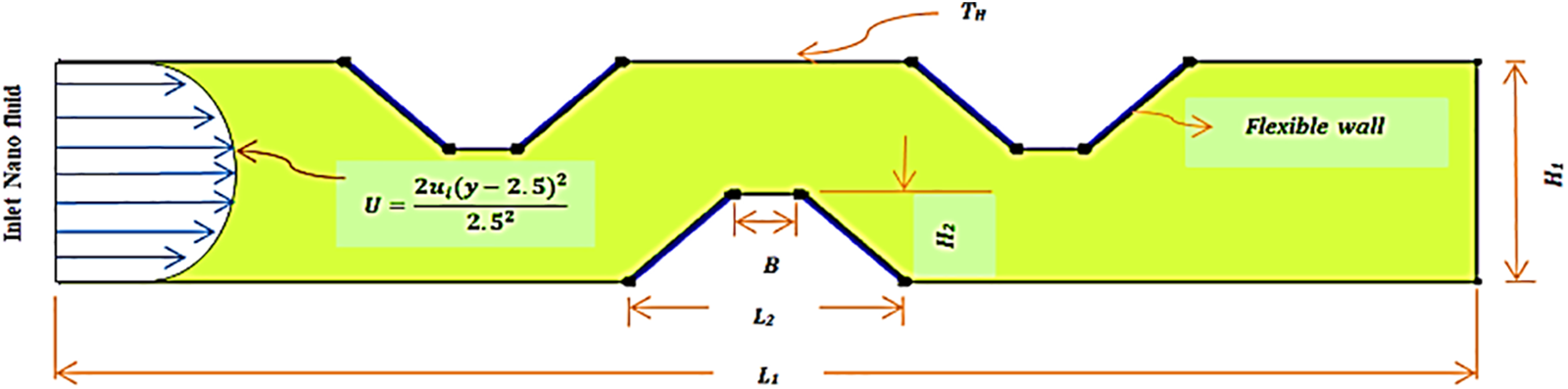
Figure 1: A diagrammatic depiction of the situation of a complicated channel that includes Flexible wall
In dimensional vector form, the governing equations of the unstable fluid and the elastic-dynamic structure are written as:
For elastic structure domain, it is possible to write the equations that describe the nonlinear elastic displacement, and the energy of the wall as follows [18]:
where (u*) is the velocity vector, (w*) identify the speed of the moving coordinates, (p*) identify the fluid pressure, (T*) identify the fluid/solid temperature, (
This stress may be described using the following form of equations. The elastic wall is subjected to a stress tensor as a result of the fluid flow pressure taking the nonlinear geometry variation [12]:
Where
where C is a function of dimensional modulus of elasticity and possin’s ratio as shown below and the colon is the double-dot tensor product.
where E is the modulus of elasticity of the wall or and v is the Poisson's ratio.
2.3 Dimensional Boundary Conditions
a) On the elastic wall, the boundary conditions are continuity of dynamic movement and kinematic forces [18]
where (u*) is the velocity vector, (p*) identify the fluid pressure, el (
b) The energy balance may be defined at the boundary between the fluid and the solid as [18]:
where Ks and Kf are the thermal conductivities of solid and fluid, respectively, and n is a normal vector.
c) The elastic wall in the present work with different positions and free displacement fixed with
d) The fluid inlet velocity is
e)
f)
The following non-dimensional parameter definitions were utilized in order to non-dimensionalize the governing equations [2]:
By substituting the non-dimensional parameters from before, the dimensional governing Eqs. (5)–(8) may be expressed in the non-dimensional form as [19]:
For the elastic Baffle [16]:
These equations have been transformed from the dimensional system to the non-dimensional system using the helpful definitions given above and also the dimensionless numbers as shown below:
The value of the body force is assumed to be zero in this calculation. (Fʋ = 0) to ease the problem as mentioned. And Ks = 10 knf.
2.4 Dimensionless Boundary Conditions
Now the previous boundary conditions for the fluid and the solid may be rewritten in a form of dimensionless as follows:
a)
b)
c)
The inlet velocity becomes U = 1, also assuming a dimensionless shape, the starting temperatures of the wall and the fluid inside the channel are both zero. In addition, the dimensionless pressure is equal to zero (P = 0).
As a result of employing the dimensionless definitions, the previous equation results in [18]:
at the point where the wall and the fluid meet one another. In addition, instantaneously integrate the instantaneous local temperature gradient to obtain the average Nusselt number is calculated by Eq. (22) over the distance of interest at the hot wall of the channel as:
where (Nu(t))av is the average Nusselt number, Li is the length of hot wall.
The preceding expression is then averaged throughout a cyclic of time (τ) using the following formula in order to get the time-averaged Nusselt number:
The skin friction coefficient interest with physical quantities of this problem which are defined as [2]:
where τw is the shear stress.
It is vital to compute a comprehensive criterion to assess the performance of the heat transfer in the current situation. This criteria is a phrase that does not have any dimensions, and it takes into consideration the process of heat transmission as well as the pressure drop that is created all the way down the channel. Utilizing this criteria, it is feasible to investigate the influence that geometrical factors have under a variety of flow situations [2]:
The subscript “o” refers to the channel that is not bewildered. The performance of mechanical may be measured in terms of the flow resistance factor, denoted by the letter “f,” which is defined as the ratio of wall shear stress to the kinetic energy of the flow. Following is an equation that was used to derive an estimate for the friction factor depending on the pressure drop readings [2]:
where ρ is density of fluid, L = 30 cm is the length of the channel, ∆p is the dimensional of pressure drop
The performance evaluation criteria (TEC) was obtained by Eq. (28). Noticeably, TEC > 1 means that improvement of heat transfer larger than pressure drop.
2.5 Effective Thermal Properties of Al2O3-Water Nano Fluid
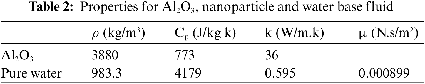
The use of Nano fluids needs to define the effective properties that are considered experimental such as heat capacity, density, viscosity, thermal conductivity and specific heat [13].
These properties are considered among the most important factors in convective properties for Al203 as nanoparticle and water as base fluid as shown in Table 2 [29].
As a direct result of the deformation of domains, specific focus should be concentrated on finding numerical solutions to FSI issues. A strategy known as the ALE method emerges as a viable option after reviewing the relevant literature. This method combines elements of both the Eulerian and the Lagrangian approaches.
The FEM was used to solve the Eqs. (13)–(20). Using a weak formulation method, the Galerkin technique is employed to solve the governing equations of the finite element methods. As can be seen in Fig. 2, the cells have been subdivided into non-structural mesh distribution components. The entirety of the computational domain makes use of finite elements Lagrange triangular of varying for the variables of pressure, temperature and velocity. The governing equations are be near to in order to derive the residuals conservation equations. To make the nonlinear momentum equations easier to solve, the Newton-Raphson technique was applied. Solution convergence is predicted if the following prerequisites are met [2].
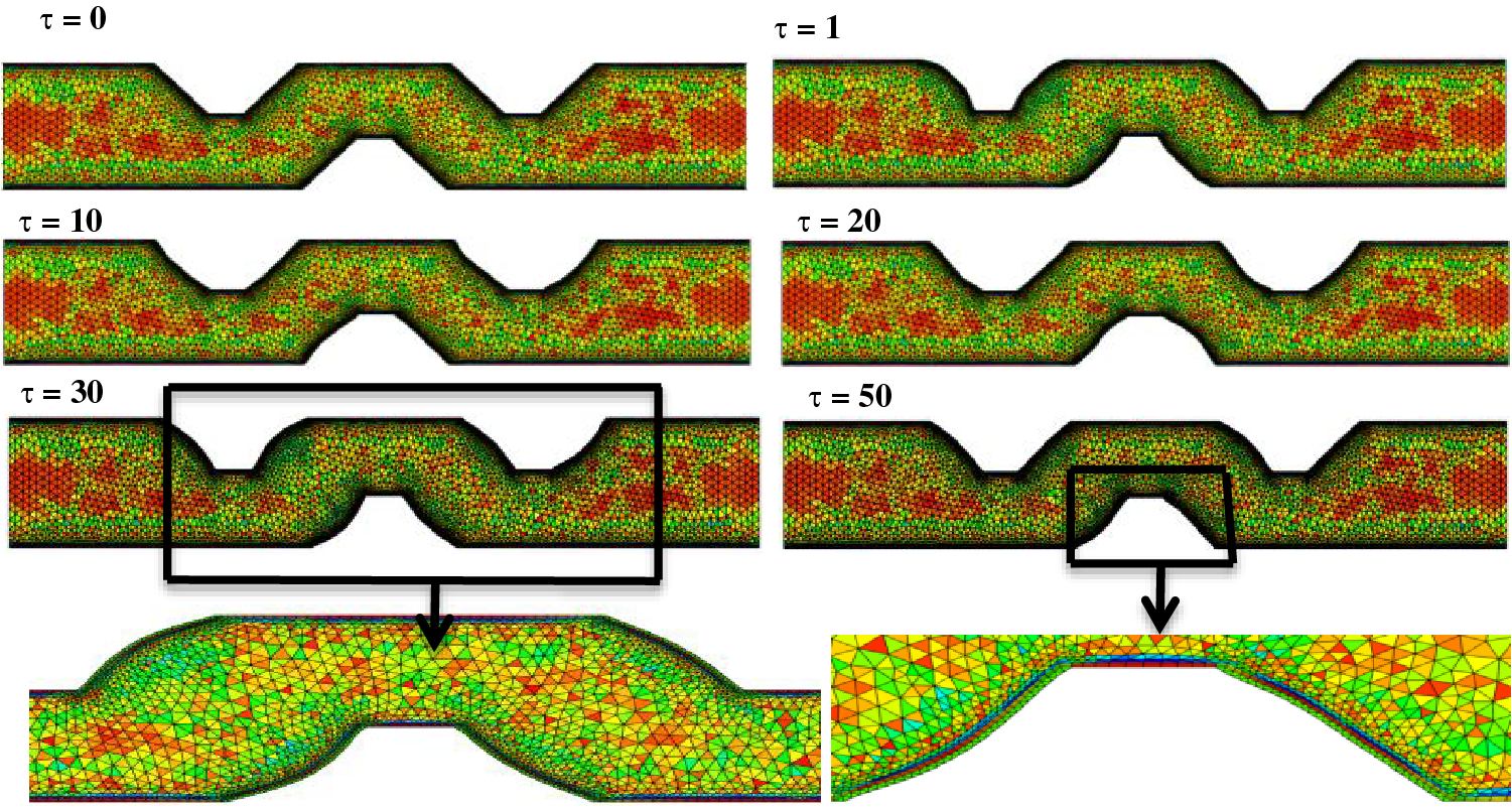
Figure 2: Mesh deformation changes over time for Re = 60, H2/L2 = 3, Ca = 10−4,
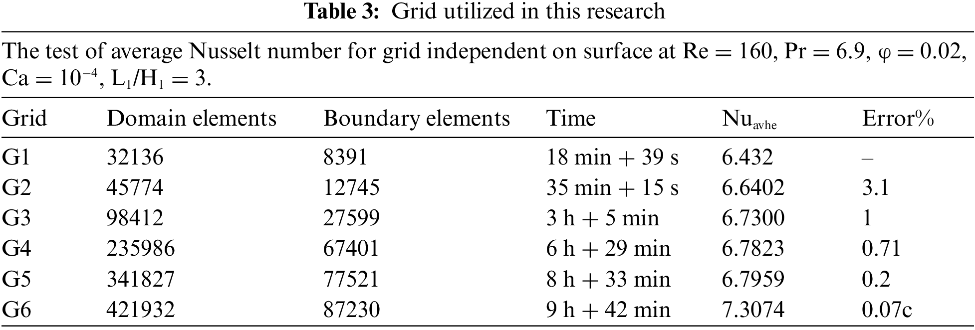
Any independent variables, where m denotes the number of iterations (velocity, temperature or pressure). To validate the correctness of the calculated findings, a grid-independent test is now required. Six grid resolutions were used to accomplish this, as shown in Table 3. The average Nusselt number on the hot surface at Ca = 1e-4, Re = 160,
This paper solved the transmission of heat for a forced convection flow problem in a complicated channel with elastic wall. The details of validated geometry Sabbar et al. [12] are displayed in Figs. 3 and 4, at Re = 150, H/D = 0.7 where H is the height of the channel and D is the height of cavity, LH = 0.9 is the length of heat source and Ri = 10. This explains the excellent concordance between the outcomes of our study and those of Sabbar et al.
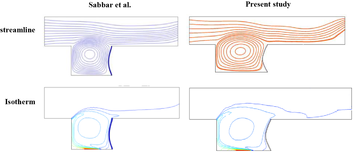
Figure 3: Constriction between several contour map of present work with Sabbar et al. [12] at Re = 150, H/D = 0.7 and Ri = 10
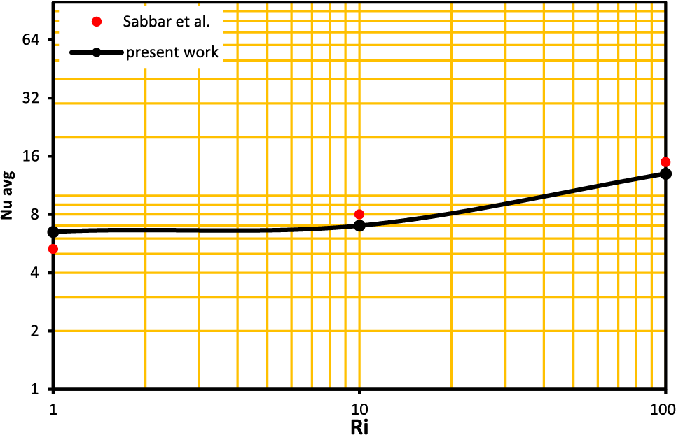
Figure 4: Constriction of Nusselt number of present work with Sabbar et al. [12] at Re = 150, H/D = 0.7 and Ri = 10
Results for streamlines, isotherms, average Nusselt numbers, fraction factors, TCE and pressure drop for Ca = 10−4 to 10−8, Re = 60 to 160, and Pr = 6.9 are shown in this section.
The investigation of the unsteady state seeks to locate the point in time at which the findings reach the steady state. In order to achieve this goal, the performance of the Nusselt number and wall deformation have been invested with time dimensionless, as can be seen in Figs. 5 and 6. A time step of 0.01 is used, and the computational work was carried on all the way up to t = 50 s. The development of the Nusselt number is seen through time in Fig. 5. In this case, considerable changes in the Nusselt number are caused by the movement of heat energy from the wall into the liquid at the beginning of time. As time passes, the layers that are closest to the wall become hotter than their initial state. As a result, the temperature difference becomes smaller, which causes the Nusselt Number to decrease until it reaches a stable state at time equal to 14 s. To demonstrate the most deformation portion of the channel at Ca = 10−4 and Re = 160, many images of the streamline flow patterns and channel behavior are collected. Fig. 6 depicts how the streamline and elastic wall behave. Due to the liquid pressure being zero on the elastic wall at time τ = 0.01 s, it can be seen that the form of the wall and the streamline are both straight and parallel. The elastic wall’s shape changes over time, becoming an arc blown to the outside of the channel at τ = 2 and τ = 3 s, before returning to contract to the inside of the channel at τ = 5 s with secondary vortex formation inside the cavity. It then continues to grow over time, reaching its largest size at τ = 10 s. The elastic wall again swells and secondary vortex is formation at τ = 14 s. When comparing τ = 14 and τ = 50 s, there are no major variations in streamline patterns. Considering these facts, it's safe to assume that the steady-state time occurs after τ = 14 s, hence all of the data in this study was collected after that point.
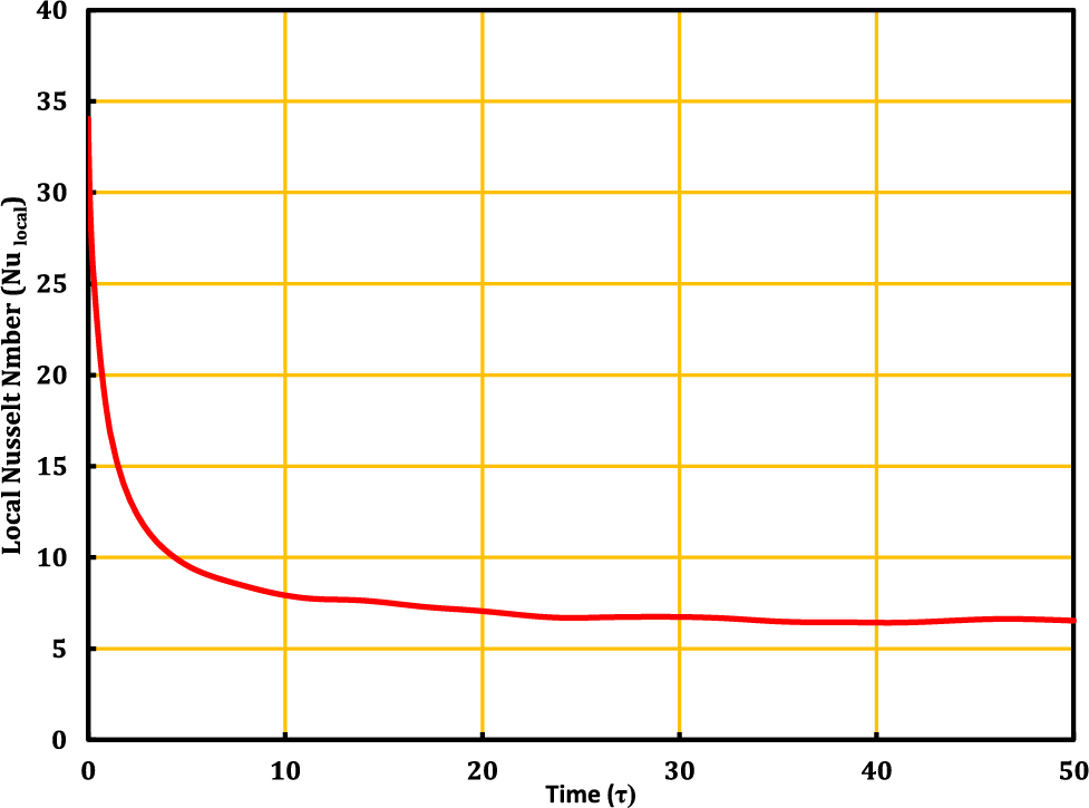
Figure 5: Average Nusselt vs. time for Re = 160, Ca = 10−4,
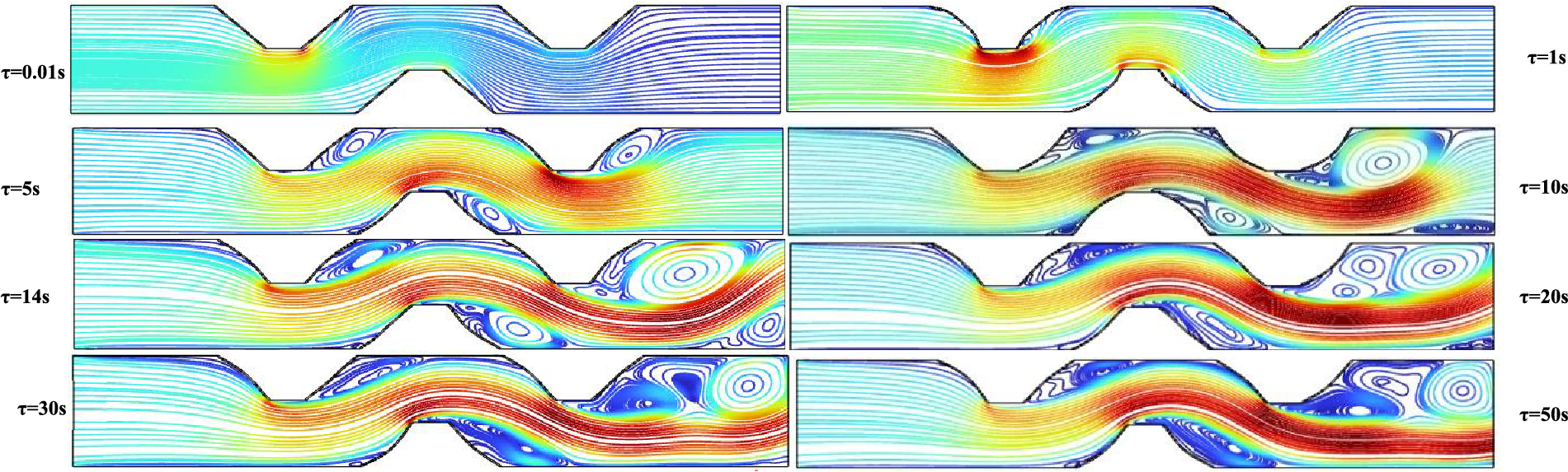
Figure 6: Wall deformation, streamlines for different values of τ at Re = 160, Ca = 10−4
5.2 Effect of Flexible Wall Position
At the parameters Pr = 6.9, Ca = 10−4,
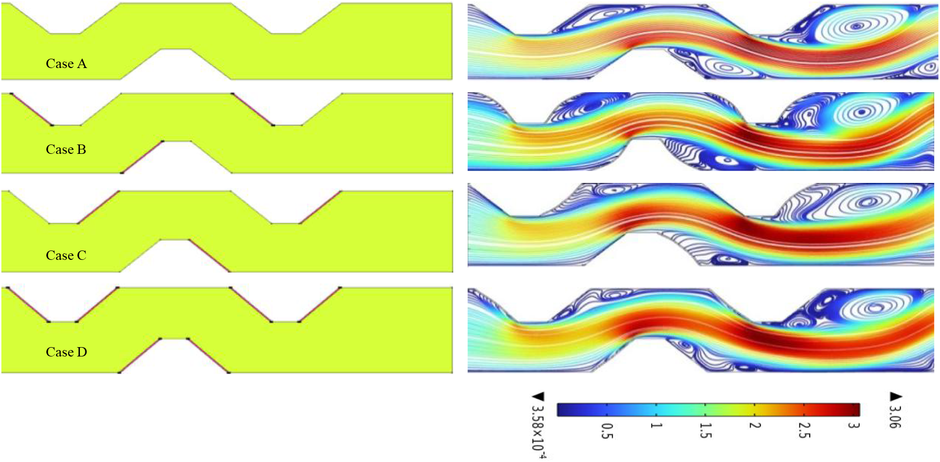
Figure 7: The streamline for the complex channel at different location of the elastic wall at Pr = 6.9, Ca = 1e-4,
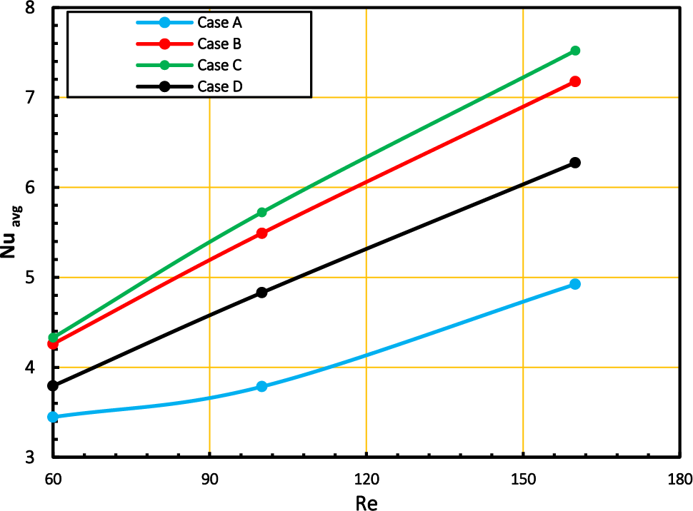
Figure 8: The relation of average Nusselt number with Reynolds number at three cases have elastic wall and comparison without elastic wall
5.3 Heat Transfer at Various Geometry
The geometries of a complicated channel with varying L2/H2 and B/H2 ratios are depicted in Fig. 9, which pertains to case C. The average of Nusselt number is investigated for each of the three possible geometries. The parameters for the L2/H2 configurations are 0, 3, and 6, with Re = 160, Pr = 6.9, and
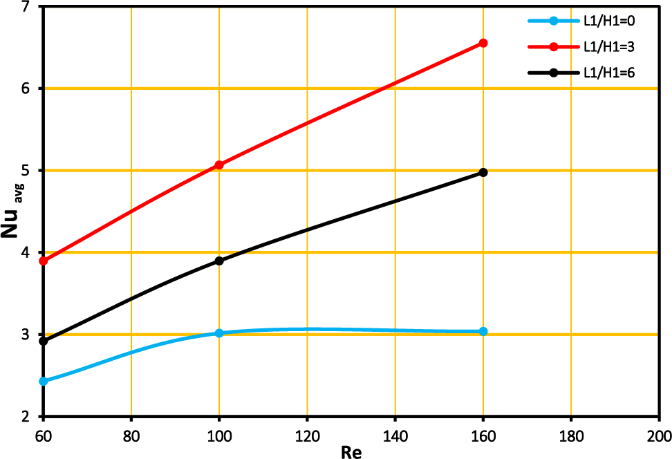
Figure 9: Nusselt number with Reynolds number at different geometry with Pr = 6.9 and
5.4 The Effect of Cauchy Number (Ca)
Calculating the Cauchy number, as illustrated in Figs. 10 and 11, is important in order to research the influence of the elastic modulus of the elastic wall on the rate of heat transfer. The streamline and isotherm maps are depicted in Fig. 10 for the following sets of parameter values: Re = 160, Pr = 6.9, Ca = 10−4 to 10−8,
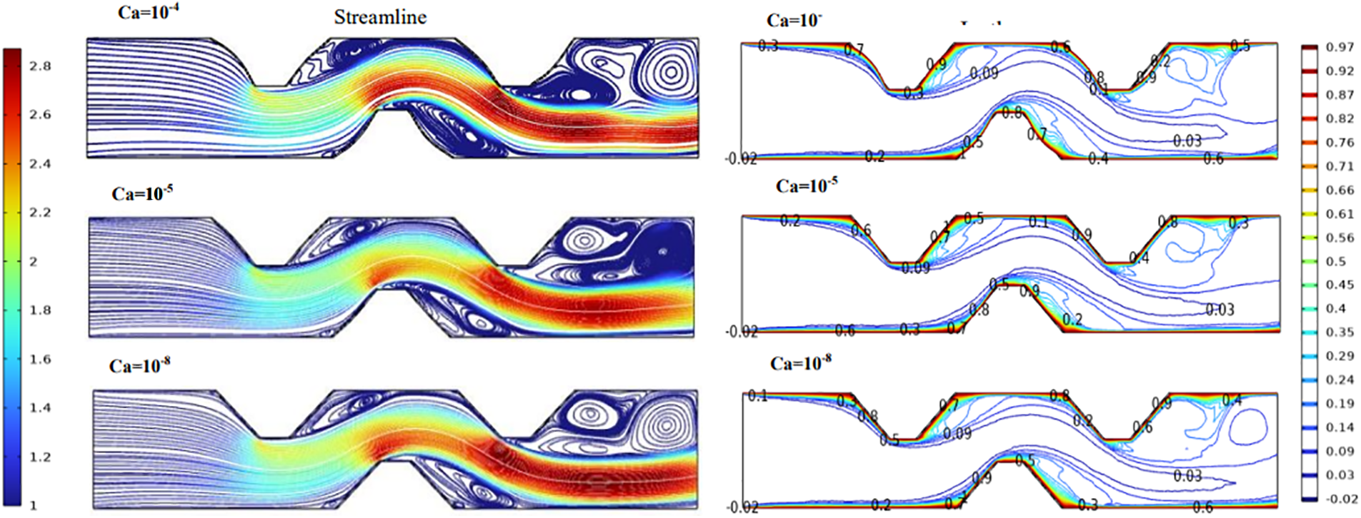
Figure 10: Stream line and isotherm for case D at Re = 160, Ca = 1e-4,
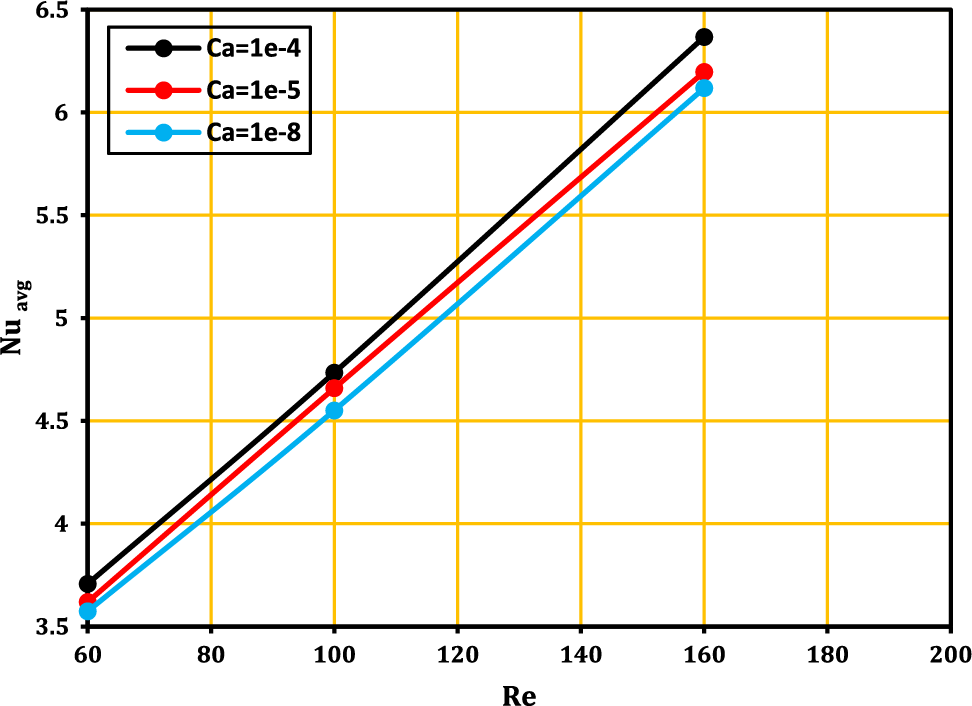
Figure 11: The relation between Reynolds number and average Nusselt number for various Cauchy number at case D at Re = 160,
5.5 The Effect of Heat Transfer for Hot Wall
The main objective in this section is to find out the sensitivity of the behavior of the elastic wall at Reynolds. The Fig. 12 shows the local Nusselt number of the FSI model along the lower wall of the channel that is indicated by the symbol(s) for different values of Reynolds numbers, where the Nusselt number suffers at the beginning of the inlet channel between (S = 0 to 2) from significant fluctuations due to the transfer of thermal energy from the wall to the liquid.
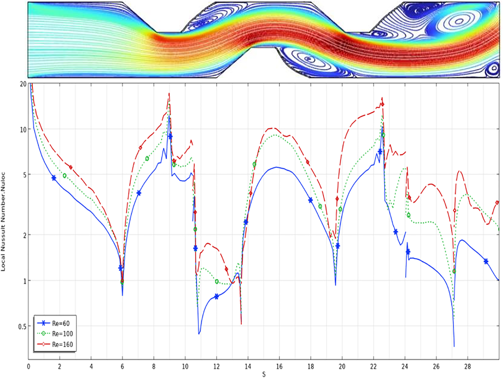
Figure 12: Local Nusselt number along the hot wall at case D with Re = 60, 100, 160, Pr = 6.9 and
Over time, the layers near the wall become hotter than the initial state, and thus the temperature difference becomes smaller, so that the Nusselt number decreases until it reaches 0.8 at S = 6. The Nusselt number returns to increasing until it reaches its maximum of 18 at S = 9 due to increased velocity at the first trapezoidal penetration in the flow. Between S = 10 and 14, the Nusselt number decreases until it reaches its minimum value of about 0.4 due to the formation of eddies at the corner of the trapezoidal. The Nusselt number is back to increase after S = 14 until reach to high value about 10 at Re = 160 and S = 16, due to acceleration flow at this location and then its drops to value 0.9 at S = 20 due to formation eddy at the bottom wall of channel. once again, the Nusselt number is growth to 27 at S = 23 for Re = 160. After S = 23, the Nusselt number is oscillated between 0.4 for Re = 60 and 5 for Re = 160 due to form main and secondary vortices at the outlet part of channel.
5.6 Impact of the Pressure Drop
It is necessary to study the pressure drop and friction factor to get the best performance because they require high pumping forces. The Fig. 13 shows the relationship of each pressure drop and friction factor with the Reynolds number for a channel containing an elastic wall, as in cases B, C, and D, and compares it with a channel without an elastic wall, as in case A. Cases B, C, and D had lower pressure drops and friction factors than case A because the elastic wall’s reciprocating motion works to renew the formation of vortices constantly, lowering the friction factor and pressure drop. The Fig. 13 also shows that as the Reynolds number increases, the pressure drop increases due to an increase in the friction factor generated by the formation of vortices, as in case A, but the opposite happens in cases B and C, where the pressure drop decreases as the Reynolds number increases due to the reciprocating movement of the elastic wall that drives out the vortices and thus a lower friction factor and pressure drop. As for case D, we notice that with a higher Reynolds number, the pressure drop is higher. This suggests that the use of merging in the elastic wall does not provide a significant benefit in terms of heat transfer.
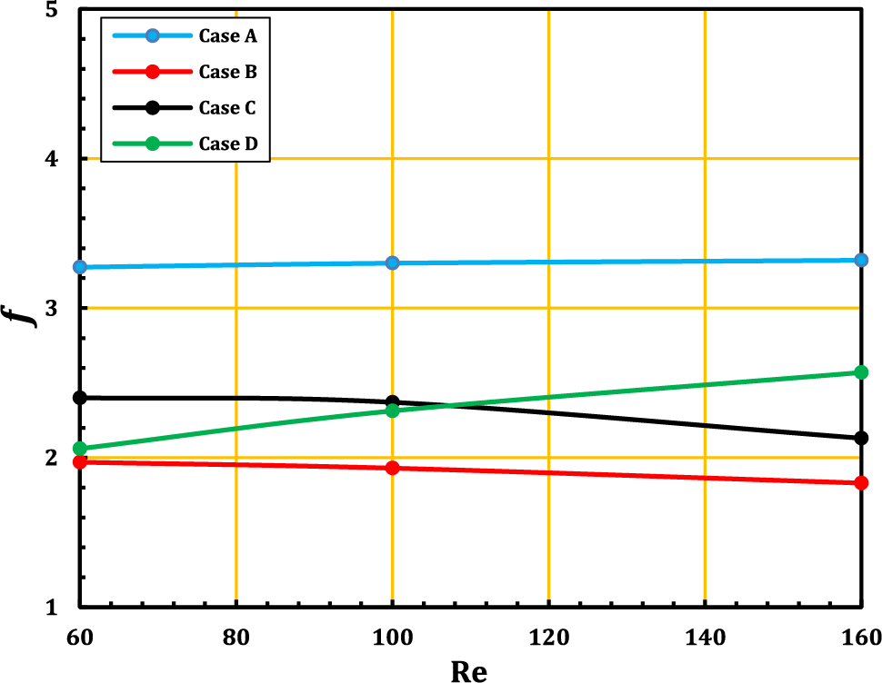
Figure 13: The relation of pressure drop and friction factor with Reynolds number at Ca = 10−4, Pr = 6.9 and
Earlier findings indicated that case C, including three elastic walls at Re = 160 and Ca = 10−4, had the optimum heat transmission performance. Because of this, in Fig. 14 the Nusselt number is attained with nanoparticles of Al2O3 at concentrations of 0 (no concentration), 0.01, 0.02, and 0.04. where the bigger the nanoparticles, the higher the Nusselt number becomes because of the increased surface area available for heat transmission as seen in the Fig. 14.
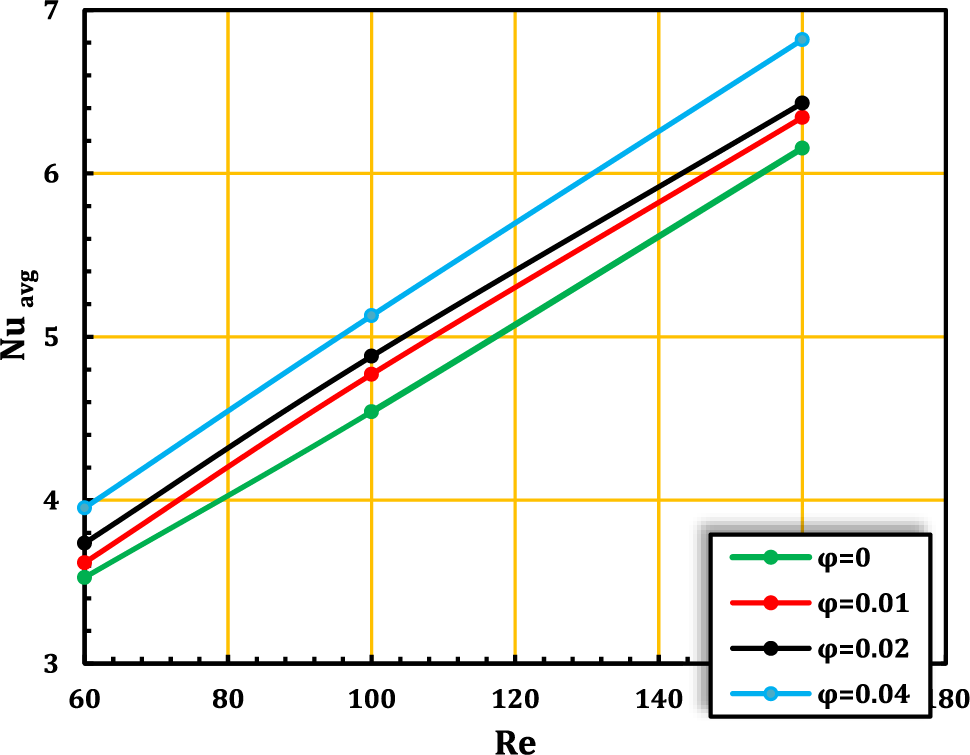
Figure 14: Average Nusselt number with nanoparticle concentration at Ca = 1e-4 and Pr = 6.9
To achieve the best performance, the friction factor and pressure drop must be calculated due to the need for high pumping power. The thermal enhancement criterion (TEC) stated in Eq. (28) can solve this problem. The best thermal enhancement criterion (TEC) can be obtained when the elastic wall is fixed after the trapezoid block of the complex channel, as shown in Fig. 15.
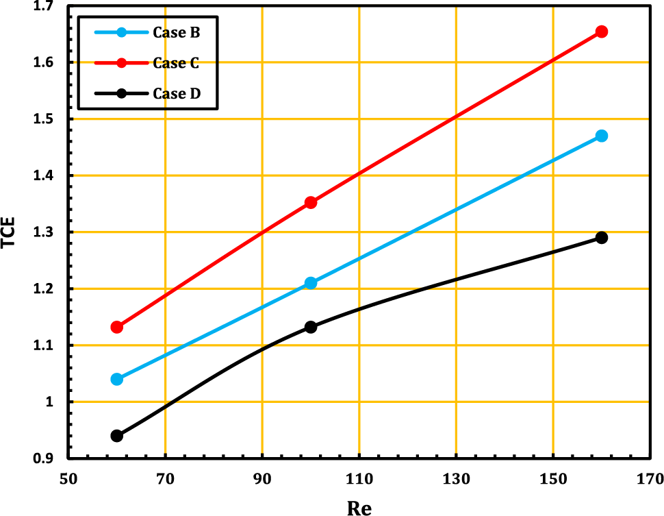
Figure 15: Variations of thermal-hydraulic performance criterion with baffles location and Reynolds numbers at Ca = 1e-4,
This means that the increase in the average Nusselt number overcomes the losses that result from the pressure drop along the channel. The high thermal enhancement criterion (TEC) is recorded at 1.68 at case C for Re = 160 and at its lowest value of 0.93 at case D for Re = 60.
This paper looks at a numerical study of how fluids and structures interact in a complex channel with a trapezoid shape hanging in it. Here, different shap of complex channel (L2/H2 and B/H2) were looked at with Reynolds numbers from 60 to 160, volume fractions from 0.02 to 0.04, a Prandtl number Pr = 6.9, and Cauchy numbers from 10−4 to 10−8. Flow can go over a hot wall, and the following conclusions were drawn:
1. The greatest Nusselt reading is obtained in case C, with a percentage of (34.5%) compared to case A without the elastic wall, but heat transmission in case B (31.4%) and D (21.5%) as compared to the channel without a flexible wall in case A.
2. Corrugated channels with B/H2 = 0.8 and L2/H2 = 3 had the best thermal performance under the current thermal conditions. This made the heat exchanger work better.
3. When Ca = 10−4 is used, the average Nusselt number is higher than when Ca = 10−5 or Ca = 10−8 is used.
4. The average Nusselt number goes up when the nanoparticles get bigger because there is more surface area for heat to move across.
5. Cases B, C, and D had lower pressure drops and friction factors than case A.
6. As the Reynolds number increases, the pressure drop increases, as in case A, but the opposite happens in cases B and C, where the pressure drop decreases as the Reynolds number increases. As for case D, the pressure drop is higher with an increase in Reynolds number. This suggests that the use of merging in the elastic wall does not provide a significant benefit in terms of heat transfer.
Acknowledgement: First of all, I would like to praise and thank GOD for helping me to complete this work. I wish to express my gratefulness to my supervisors, Prof. Dr. Hameed Kadhem Hamzah and Prof. Dr. Hatem Hadi Obied Said for their continuous supervision, positive discussions and important ideas through this research work. Also, very extraordinary deepest thanks to Dr. Farooq H. Ali for his special contribution and help in completing this work. My deepest thanks, love and gratitude for all of My family. This work would not have been completed without their love and continuous support.
Funding Statement: The authors received no specific funding for this study.
Author Contributions: Data collection, analysis and interpretation of results: Amal A. Harbood, study conception and design: Hameed K. Hamzah, draft manuscript preparation: Hatem H. Obied.
Availability of Data and Materials: Data are available upon request.
Conflicts of Interest: The authors declare that they have no conflicts of interest to report regarding the present study.
References
1. Al-Amiri, A., Khanafer, K. (2011). Fluid-structure interaction analysis of mixed convection heat transfer in a lid-driven cavity with a flexible bottom wall. International Journal of Heat and Mass Transfer, 54(17–18), 3826–3836. [Google Scholar]
2. Yaseen, D. T., Ismael, M. A. (2020). Effect of deformable baffle on the mixed convection of non-Newtonian fluids in a channel-cavity. Basrah Journal for Engineering Science, 20(2), 18–26. [Google Scholar]
3. Xu, H., Liao, S. J. (2009). Laminar flow and heat transfer in the boundary-layer of non-Newtonian fluids over a stretching flat sheet. Computers & Mathematics with Applications, 57(9), 1425–1431. [Google Scholar]
4. Hessenthaler, A., Gaddum, N. R., Holub, O., Sinkus, R., Röhrle, O. et al. (2017). Experiment for validation of fluid-structure interaction models and algorithms. International Journal for Numerical Methods in Biomedical Engineering, 33(9), e2848. [Google Scholar] [PubMed]
5. Korei, Z., Benissaad, S., Chamkha, A., Berrahil, F., Filali, A. (2022). Thermohydraulic and second law analyses during the cooling of an electronic device mounted in an open cavity equipped with magnetic nanofluid, magnetic field inducer, and porous media: A two-phase numerical investigation. International Communications in Heat and Mass Transfer, 139(318), 106497. [Google Scholar]
6. Selimefendigil, F., Öztop, H. F. (2016). Analysis of MHD mixed convection in a flexible walled and nanofluids filled lid-driven cavity with volumetric heat generation. International Journal of Mechanical Sciences, 118, 113–124. [Google Scholar]
7. Selimefendigil, F., Öztop, H. F., Abu-Hamdeh, N. (2016). Mixed convection due to rotating cylinder in an internally heated and flexible walled cavity filled with SiO2-water nanofluids: Effect of nanoparticle shape. International Communications in Heat and Mass Transfer, 71, 9–19. [Google Scholar]
8. Selimefendigil, F., Öztop, H. F., Chamkha, A. J. (2017). Analysis of mixed convection of nanofluid in a 3D lid-driven trapezoidal cavity with flexible side surfaces and inner cylinder. International Communications in Heat and Mass Transfer, 87, 40–51. [Google Scholar]
9. Selimefendigil, F., Öztop, H. F., Chamkha, A. J. (2017). Fluid-structure-magnetic field interaction in a nanofluid filled lid-driven cavity with flexible side wall. European Journal of Mechanics-B/Fluids, 61, 77–85. [Google Scholar]
10. Jamesahar, E., Ghalambaz, M., Chamkha, A. J. (2016). Fluid-solid interaction in natural convection heat transfer in a square cavity with a perfectly thermal-conductive flexible diagonal partition. International Journal of Heat and Mass Transfer, 100(1), 303–319. [Google Scholar]
11. Mehryan, S., Ghalambaz, M., Ismael, M. A., Chamkha, A. J. (2017). Analysis of fluid-solid interaction in MHD natural convection in a square cavity equally partitioned by a vertical flexible membrane. Journal of Magnetism and Magnetic Materials, 424(14), 161–173. [Google Scholar]
12. Sabbar, W. A., Ismael, M. A., Almudhaffar, M. (2018). Fluid-structure interaction of mixed convection in a cavity-channel assembly of flexible wall. International Journal of Mechanical Sciences, 149, 73–83. [Google Scholar]
13. Selimefendigil, F., Öztop, H. F. (2018). Laminar convective nanofluid flow over a backward-facing step with an elastic bottom wall. Journal of Thermal Science and Engineering Applications, 10(4), 041003. [Google Scholar]
14. Selimefendigil, F., Öztop, H. F. (2019). MHD mixed convection of nanofluid in a flexible walled inclined lid-driven L-shaped cavity under the effect of internal heat generation. Physica A: Statistical Mechanics and its Applications, 534, 122144. [Google Scholar]
15. Selimefendigil, F., Öztop, H. F. (2019). Fluid-solid interaction of elastic-step type corrugation effects on the mixed convection of nanofluid in a vented cavity with magnetic field. International Journal of Mechanical Sciences, 152, 185–197. [Google Scholar]
16. Ismael, M. A. (2019). Forced convection in partially compliant channel with two alternated baffles. International Journal of Heat and Mass Transfer, 142, 118455. [Google Scholar]
17. Alsabery, A. I., Saleh, H., Ghalambaz, M., Chamkha, A. J., Hashim, I. (2019). Fluid-structure interaction analysis of transient convection heat transfer in a cavity containing inner solid cylinder and flexible right wall. International Journal of Numerical Methods for Heat & Fluid Flow, 29(10), 3756–3780. [Google Scholar]
18. Ghalambaz, M., Mehryan, S. A. M., Ismael, M. A., Chamkha, A., Wen, D. (2019). Fluid-structure interaction of free convection in a square cavity divided by a flexible membrane and subjected to sinusoidal temperature heating. International Journal of Numerical Methods for Heat & Fluid Flow, 30(6), 2883–2911. [Google Scholar]
19. Al-Amir, Q. R., Hamzah, H. K., Abdulkadhim, A., Ahmed, S. Y., Ali, F. H. et al. (2022). Numerical study of fluid structure interaction of four flexible fins inside nanofliud-filled square enclosure containing hot circular cylinder. Journal of Thermal Analysis and Calorimetry, 147(23), 1–19. [Google Scholar]
20. Burgmann, S., Große, S., Schröder, W., Roggenkamp, J., Jansen, S. et al. (2009). A refractive index-matched facility for fluid-structure interaction studies of pulsatile and oscillating flow in elastic vessels of adjustable compliance. Experiments in Fluids, 47(4–5), 865–881. [Google Scholar]
21. Elshafei, E. A. M., Awad, M. M., El-Negiry, E., Ali, A. G. (2010). Heat transfer and pressure drop in corrugated channels. Energy, 35(1), 101–110. [Google Scholar]
22. Ahmed, M. A., Yusoff, M. Z., Ng, K. C., Shuaibl, N. H. (2015). Numerical and experimental investigations on the heat transfer enhancement in corrugated channels using SiO2-water nanofluid. Case Studies in Thermal Engineering, 6, 77–92. [Google Scholar]
23. Korei, Z., Berrahil, F., Filali, A., Benissaad, S., Boulmerka, A. (2023). Thermo-magnetic convection analysis of magnetite ferrofluid in an arc-shaped lid-driven electronic chamber with partial heating. Journal of Thermal Analysis and Calorimetry, 148(6), 1–20. [Google Scholar]
24. Ajeel, R. K., Salim, W. S., Hasnan, K. (2018). Numerical investigations of flow and heat transfer enhancement in a semicircle zigzag corrugated channel using nanofluids. International Journal of Heat and Technology, 36(4), 1292–1303. [Google Scholar]
25. Ajeel, R. K., Salim, W. I., Hasnan, K. (2019). An experimental investigation of thermal-hydraulic performance of silica nanofluid in corrugated channels. Advanced Powder Technology, 30(10), 2262–2275. [Google Scholar]
26. Naphon, P. (2008). Effect of corrugated plates in an in-phase arrangement on the heat transfer and flow developments. International Journal of Heat and Mass Transfer, 51(15–16), 3963–3971. [Google Scholar]
27. Sakr, M. (2015). Convective heat transfer and pressure drop in V-corrugated channel with different phase shifts. Heat and Mass Transfer, 51(1), 129–141. [Google Scholar]
28. Ajeel, R. K., Saiful-Islam, W., Sopian, K., Yusoff, M. Z. (2020). Analysis of thermal-hydraulic performance and flow structures of nanofluids across various corrugated channels: An experimental and numerical study. Thermal Science and Engineering Progress, 19(133), 100604. [Google Scholar]
29. Salami, M., Khoshvaght-Aliabadi, M., Feizabadi, A. (2019). Investigation of corrugated channel performance with different wave shapes: Nanofluid as working media. Journal of Thermal Analysis and Calorimetry, 138(5), 3159–3174. [Google Scholar]
30. Al-Zurfi, N., Alhusseny, A., Nasser, A. (2020). Effect of rotation on forced convection in wavy wall channels. International Journal of Heat and Mass Transfer, 149(11–12), 119177. [Google Scholar]
Cite This Article
 Copyright © 2023 The Author(s). Published by Tech Science Press.
This work is licensed under a Creative Commons Attribution 4.0 International License , which permits unrestricted use, distribution, and reproduction in any medium, provided the original work is properly cited.
 Downloads
 Citation Tools