
 Submit a Paper
 Propose a Special lssue
 Open Access
ARTICLE

Numerical Assessments on Flow Topology and Heat Transfer Behavior in a Round Tube Inserted with Three Sets of V-Ribs
1
Department of Mechanical Engineering Technology, College of Industrial Technology, King Mongkut’s University of Technology
North Bangkok, Bangkok, 10800, Thailand
2
Department of Mechanical Engineering, School of Engineering, King Mongkut’s Institute of Technology Ladkrabang,
Bangkok, 10520, Thailand
* Corresponding Author: Withada Jedsadaratanachai. Email:
Frontiers in Heat and Mass Transfer 2023, 21, 81-106. https://doi.org/10.32604/fhmt.2023.041547
Received 26 April 2023; Accepted 30 May 2023; Issue published 30 November 2023
 View Full Text
 Download PDF
Abstract
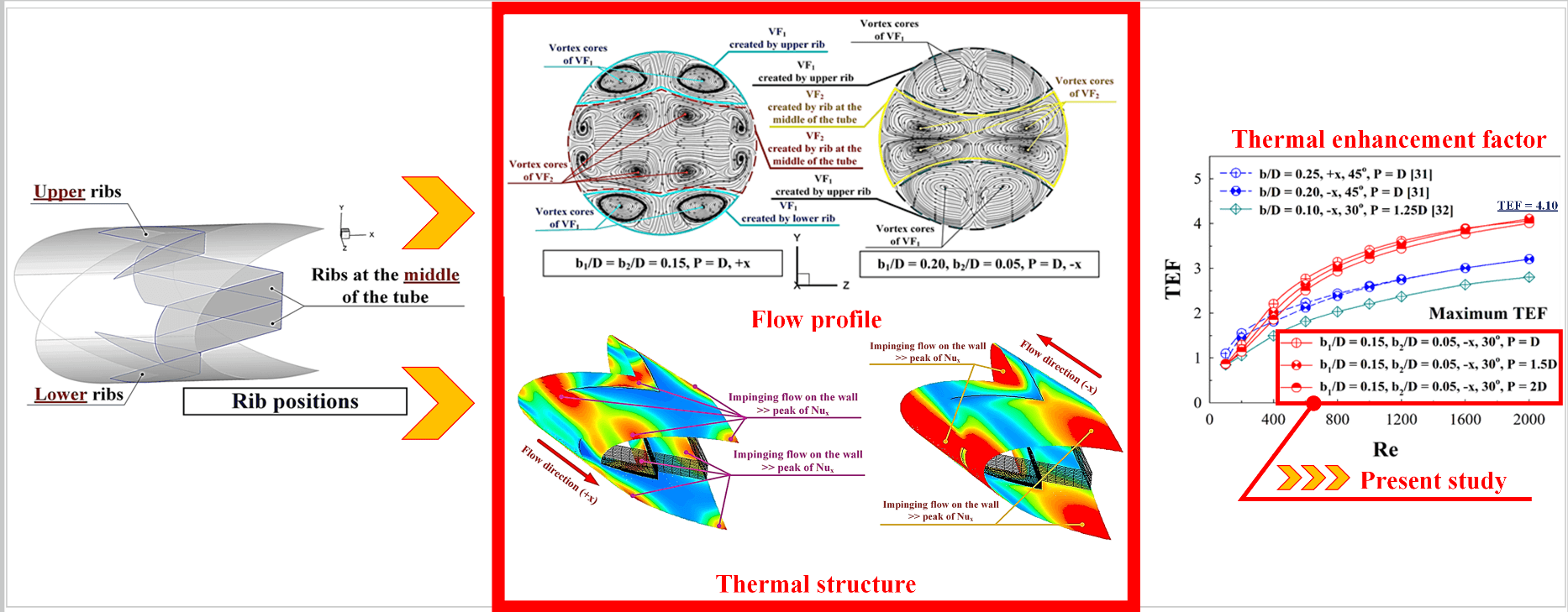
Simulation of fluid-flow topology and thermal behavior in a round tube heat exchanger (RTHX) installed by three V-rib sets is reported. The expected phenomena for the rib installation are the generated vortex flow, impinging flow, greater fluid blending and thermal boundary layer disturbance (TBLD). These phenomena are key causes of the augmentation of heat transfer potentiality and thermal efficiency of the RTHX. Effects of rib height (b1 = 0.05D – 0.25D and b2 = 0.05D – 0.25D), rib pitch or rib spacing (P = D, 1.5D and 2D) and fluid directions (positive x (+x flow direction) and negative x (–x flow direction)) on fluid-flow behavior and thermo-hydraulic characteristic are considered. The laminar air flow under Reynolds numbers between 100 to 2000 calculated by the inlet condition is focused. The current numerical problem of the RTHX fitted with V-ribs can be solved by a commercial code/program (the finite volume analysis). Firstly, the tested-tube model is carefully validated. The preliminary results of the validation show that the numerical model has great consistency for fluid flow and thermal structure prediction. The simulated outcomes are plotted in features of streamlines flow, local Nusselt number contours and temperature contours which explain the mechanism within the RTHX. The thermal assessments within the RTHX are performed with dimensionless variables, which include the Nusselt number, the friction factor and the thermal enhancement factor. The important mechanisms: vortex flow, impinging flow, better fluid blending and TBLD, are observed when the RTHX are installed with ribs. The maximum heat transfer potentiality is 19 times upper than that of the RTHX without ribs and the optimum thermal enhancement factor is around 4.10.Graphic Abstract
Keywords
Nomenclature
| b | Baffle height, m |
| D | Tube diameter, m |
| f | Friction factor |
| h | Convective heat transfer coefficient, W m−2 K−1 |
| k | Thermal conductivity, W m−1 K−1 |
| L | Numerical model length/periodic length |
| Nu | Nusselt number (=hD/k) |
| p | Static pressure, Pa |
| P | Pitch distance, m |
| Re | Reynolds number |
| T | Temperature, K |
| Mean velocity in tube, m s−1 | |
| ρ | Density, kg m−3 |
| TEF | Thermal enhancement factor (=(Nu/Nu0)/(f/f0)1/3) |
| Subscript | |
| 0 | Smooth circular tube |
| pp | Pumping power |
“Energy conservation and management” is an important topic for many industries due to the increase of the energy consumption in the world. Many engineering and R&D teams have been engaging in various initiatives to achieve energy conservation and management. Greater thermal performance or efficiency for many engineering devices such as boilers, thermal systems, and especially heat exchanges, is key to energy conservation and management. Heat exchangers are important devices used in various processes. Shell-and-tube heat exchangers, plate-fin heat exchangers, fin-and-tube heat exchangers, etc., are types of heat exchangers. Nowadays, the improvement of thermal performance in various heat exchangers and thermal systems had been conducted by both passive and active methods/techniques. In general, the passive method is commonly employed to increase the heat exchanger performance because it does not need additional force to increase the heat-exchanger performance. The passive method involves a placement of the turbulators/vortex generators/vortex turbulators into the thermal system to produce the vortex flows/vortex streams which change the configuration of the thermal boundary layer or TBL over the heat transfer surfaces. The change of the TBL increases the convective heat transfer coefficient which leads to the augmentation of the heat transfer ability and the thermo-hydraulic efficiency. Ribs [1,2], baffles [3,4], winglets [5], wings [6], wavy surface [7], etc., are types of turbulators. The selection of turbulators depends on the application of heat exchangers and thermal systems.
Many laboratories have employed the passive methods for the improvement of heat exchangers through experimental and numerical investigations. They observed that the type, parameter, placement, size, etc., of the turbulator are significant factors that contribute to the change of the thermal and flow structures which impact heat transfer ability, thus rising heat exchanger performance. For example, Singh et al. [8] evaluated perforated multi-V rib turbulators to augment heat transfer ability of double pass solar air heater. Their results revealed that the perforation of the multi-V ribs resulted in greater Nusselt number and thermo-hydraulic performance than that of the normal multi-V ribs. Zhao et al. [9] enhanced the heat transfer coefficient of supercritical n-decane inside a cooling channel by using triangular ribs for regenerative cooling. The impact of turbulator position, turbulator size and pitch/spacing on thermal potentiality were examined. As the results, they found that heat transfer ability was enhanced when the rib had high inclination. Jiang et al. [10] examined the thermal efficiency of mist-steam coolant within a straight channel with 45°, 60°, 75° V-shaped ribs and 45°, 60°, 75°, 90° paralleled ribs. They concluded that the 45° V-pattern ribbed channel resulted in the greatest cooling improvement. The average Nusselt number ratio of the 45° V-shaped ribbed passage was better than that of the 90° paralleled ribbed section. Zhang et al. [11] presented the increased thermal potentiality and augmented heat transfer ability within a solar air heater by applied modified transverse ribs as vortex turbulators. The improved heat transfer through the tested section with the novel ribs was around 1.9 times greater than that of the smooth section. The best thermo-hydraulic performance observed in this study was 1.51. Zhang et al. [12] reported the turbulent flow topology and thermal profile within a tested channel installed with micro V-profile rib and dimple turbulators. They observed that the hybrid turbulator (micro V-profile rib-dimple) promoted even more pronounced heat transfer augmentation. Krishnaswamy et al. [13] enhanced the thermal potentiality for a gas turbine by installing continuous V and W-profile ribs as a passive method. They observed that the best heat transfer was 3.9 and 3.8 above the reference case with the V-ribs and W-ribs, respectively. They also showed that the tested sections installed with the V-rib and W-rib turbulators resulted in the best thermal-hydraulic performance of 3.3 and 3, respectively. Jiang et al. [14] presented the increased convective heat transfer coefficient of a liquid cold plate by using mini V-profile ribs for battery thermal management. The fluid-flow topology and thermal mechanism by various-rib shapes were discussed. They observed that the triangular cross-section could reach similar thermal performance with lower pumping force. Zhu et al. [15] considered the fluid-flow characteristics and the thermal structure inside a U-shaped channel heat exchanger with side-wall column ribs. Lori et al. [16] numerically simulated fluid flows and thermal behaviors within a microchannel heat exchanger installed with vertical solid and porous rib turbulators. The various rib shapes: elliptical, rectangular, backward triangular, isosceles triangular, and forward triangular, were considered. The heat transfer ability inside the microchannel attached with the porous-rib averaged was 1.3–2.16 times upper than that of the solid case and 2.505–4.01 times better than that of the plain microchannel. The improved-thermal efficiency of an indoor designed jet impingement solar thermal collector using discrete multi-arc ribs was reported by Kumar et al. [17]. They showed that the best Nusselt number and friction loss of their study were 7.61 and 6.48 times greater than that of the plain section without turbulator, respectively, while the optimal thermo-hydraulic performance was 4.1. Bhuvad et al. [18] selected discrete arc ribs with apex-up to improve solar-air-heater performance. The angles of attacks for the ribs: 30°, 45° and 60°, were compared at the Reynolds number of 3,000–14,000. Their results showed that the best angle of attack is 30°. It provided the best Nusselt number which is 2.92 times higher than that of the general channel without ribs (reference case). Sujoy et al. [19] investigated the hydro-thermal characteristics of the laminar stream within a tested-square duct fitted with helical screw-tapes and transverse ribs. Their outcomes revealed that enhancing the Reynolds number and rib height increased the forced convection, while increasing in the rib spacing and the screw tape parameter value reduced it. Zhao et al. [20] selected combined vortex generators (combined structures between ribs with delta winglets) to increase solar-air-heater performance. The thermal performance of various rib configurations: 90° truncated ribs, 90° continuous ribs, 60° V-profile truncated ribs and 60° V-profile continuous ribs, was investigated. Their results revealed that the optimal combination of the vortex generators was the 60° V-profile continuous ribs with delta winglets which provided the improved heat transfer rate of 39.4% as compared to the single turbulator (delta winglet alone). Chang et al. [21] reported the effects of angled ribs and pin fins on aerothermal potentiality in a three-pass channel. They concluded that the endwall-average Nusselt number of the pin-fin pass inside the effusion channel was 1.68–1.44 times higher than that of the non-effusion channel, while the friction factor was 0.25–0.33 times lesser than that of the non-effusion channel. The effects of staggered-rib diameters on flow boiling heat transfer in a heat sink were investigated by Qi et al. [22]. Their results revealed that the average heat transfer coefficient augmented and the wall temperature declined with an increase in the rib diameter. The best configuration of the rib was presented. A CFD assessment within a solar-air-heater by applying polygonal and trapezoidal ribs as a passive method was introduced by Kumar et al. [23]. The best thermo-hydraulic performance was 1.89, which was found in the case of the backward trapezoidal rib, Re = 15,000. Aerothermal dynamics within a channel equipped with micro ribs was introduced by Zhao et al. [24]. They found that the micro rib was a potential cooling method to achieve great heat transfer with smaller friction loss that led to an increase in the overall-thermal efficiency of the gas turbine. Tanda et al. [25] conducted the experimental and numerical investigations of pressure loss and heat transfer ability through a high AR rectangular duct fitted by angled and intersecting rib turbulators. They concluded that the thermal efficiency (at similar pumping force) augmented with the addition of one intersecting rib, but the two intersecting ribs did not result in significant performance improvement. Thermo-hydraulic assessments of a novel hybrid nanofluid in a microchannel heat sink with sinusoidal cavities and rectangular ribs were studied by Jamshidmofid et al. [26]. The maximum augmented heat transfer coefficient was 14% higher compared with the reference. Gill et al. [27] improved hybrid ribs (broken arc and staggered ribs) to enhance heat transfer potentiality through thermal system (solar air heater). They reported that the proposed new configuration provided an increase in pressure loss and heat transfer coefficient by 2.57 and 3.16 times, respectively, when compared with a general system. Dong et al. [28] enhanced the energy performance of a PEM fuel cell by introducing discontinuous S-shaped and crescent ribs into flowing channels. Their results showed that the pressure loss was reduced, and the electrochemical efficiency was increased by up to 23.61% in the high current density condition, as compared with those of the baseline sinusoidal ribbed flow field. Experimental and numerical studies on flow and thermal patterns through a rectangular channel equipped with perforated rib turbulators were conducted by Liu et al. [29]. They observed that the local heat transfer coefficient could be enhanced by 12%–24%, and 4%– 8% for the overall heat transfer. They also concluded that the overall thermal performance of the ribbed channel enhanced with a slight pressure drop.
As published in earlier works, the V-ribs are highly effective in increasing the convective heat transfer coefficient. They were typically placed on the tube/duct wall, added at the center of the circular tube (along tube diameter)/duct or inserted diagonally within the square duct. The V-rib installation on both positions (tube wall and tube core) has not been reported. In this study, three sets of the V-profiles ribs located on the tube surface and inserted in the middle of the tube are used as vortex-flow producers in a round tube heat exchanger (RTHX). The three sets of the V-ribs are expected to increase the vortex strength, impinging-flow force and turbulent blending efficiency. Moreover, the optimum parameters, placements and fluid-flow directions of the V-ribs for increasing thermal efficiency are investigated. The numerical method or numerical investigation based on a commercial code/program is used to answer the current-numerical question. The numerical investigation is a suitable method as it can offer insights about the mechanism within the RTHX, which is crucial for improving the heat-exchanger performance.
2 Description of Numerical Model, Assumption and Boundary Conditions
The system of interest is a RTHX equipped with three sets of V-profile ribs (see Fig. 1). Two sets of the ribs are placed on the tube wall in an opposite arrangement (in-line arrangement), while the other set of the rib is added at the middle of the RTHX (see Fig. 2). The tube diameter, D, is 50 mm. The flow attack angle of 30° is assigned for all simulation cases. The rib height is presented as “b”. b1 refers to the rib height of the ribs which are placed over the tube surface, while b2 refers to the rib height of the ribs inserted in the middle of the RTHX (along tube diameter). The distance between ribs is presented by P. The ratios of rib height to tube diameter, both b1/D and b2/D, are varied within the range of 0.05–0.25. The relations of pitch spacing to tube diameter, P/D, of 1, 1.5 and 2, are studied. The laminar air flow within the Reynolds number ranging from 100–2000 at the entrance conditions is focused. The fluid-flow directions of the RTHX, +x and −x are investigated.
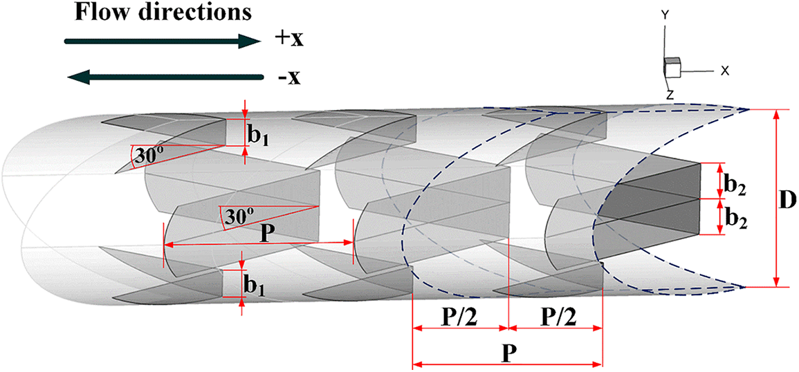
Figure 1: RTHX model and parameters
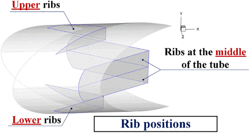
Figure 2: Rib positions
The boundary conditions of the numerical domain for the RTHX fitted with three rib sets are illustrated in Fig. 3. The ribs are set to be an insulator. Entry and exit regions for the numerical model are set with periodic boundary. The periodic boundary means that the flow and thermal profiles repeat itself from one to another module. Uniform temperature of 310 K is set at the tube wall.
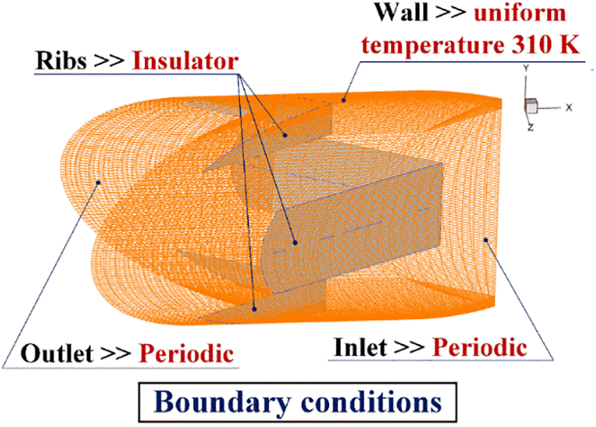
Figure 3: Periodic module of the RTHX inserted with three sets of the V-ribs and boundary conditions
The no-slip wall condition is adopted for all tested tube surfaces. The working fluid within the RTHX is air with a preliminary temperature of 300 K (Prandtl number of 0.707). As the maximum temperature difference of the present work is 10 K, the air properties are considered constant values. 3D steady flow and thermal profiles are set for the present numerical model. The flow is assumed to be laminar and incompressible flow. Effect of body force and viscous dissipation on the flow and thermal behaviors are not considered. Convective heat transfer in the RTHX is discussed, while the other heat transfer modes (radiation heat transfer and free convection) are not accounted.
With the above assumptions and initial conditions, the governing equations are the continuity equation, the momentum equation and the energy equation in tensor form are presented in Eqs. (1–3), respectively.
Continuity equation:
Momentum equation:
Energy equation:
where, Γ is the thermal diffusivity and is written as
A commercial code based on the finite volume method is employed. As for the numerical settings, the continuity equation and the momentum equation are discretized by the power law numerical-scheme, while the energy equation is discretized by the QUICK numerical scheme. For the momentum and continuity equations, the primary results pointed out that the numerical data are consistent with varied numerical schemes (i.e., first order upwind, second order upwind and power law numerical-schemes). Convergence of the computational data is achieved when the normalized residual values are lesser than 10−5 for the continuty and mometum equations and are not more than 10−9 for the energy equation.
In the present study, important variables are shown in features of dimensionless variables. The air velocity at the entry condition of the RTHX is offered in features of Reynolds number (Re). The Reynolds number can be determined by Eq. (5).
Reynolds number:
The pressure drop or pressure loss across the V-rib in the RTHX is calculated in terms of by the friction factor (f) as shown in Eq. (6).
Friction factor:
Forced convective heat transfer within the ribbed tube can be computed by local Nusselt number (Nux) and averaged Nusselt number (Nu) which are shown in Eqs. (7) and (8), respectively.
Local Nusselt number:
Averaged Nusselt number:
The rib installation within the RTHX rises both heat transfer and friction loss. The advantages of rib placement can be analyzed by considering the augmentation of heat transfer ability and friction loss at an identical pumping force. The variable which is selected to describe the rib benefit is thermal enhancement factor (TEF). The TEF of the ribbed tube can be calculated by Eq. (9).
Thermal enhancement factor:
Subscript “0” means the RTHX without rib (reference value) variables.
A significant process for a numerical study or simulation is numerical-model validation. The validated results can be used to assess the accuracy and the precision of the results. For laminar-air flow, the numerical validation needed are the plain tube validation and the grid independence/optimum grid check. For the plain tube validation, the predictions of heat transfer and pressure loss are compared with the correlation data Cengel et al. [30]. The heat transfer rate can be shown in features of Nusselt number, while the pressure loss can be presented by friction factor value. The results from the validation showed that the deviations of Nusselt number and friction factor values are not higher than ±5%, and are therefore acceptable (see Fig. 4).
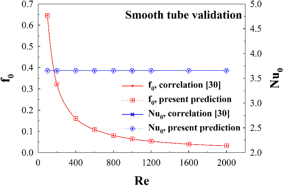
Figure 4: Smooth tube validation
As for the grid independence, the computational domain for the RTHX installed with the V-profile ribs (P = D, +x and −x flow directions, b1/D = b2/D = 0.10) at various grid elements: 80000, 120000, 180000, 240000, 360000, are compared (see Fig. 5). The results reveal that the numerical model with the grid element 180000–360000 results in similar data of both Nusselt number and friction factor values. When considering the investigated time and computer resource, the present computational model is produced with the grid element of 180000.
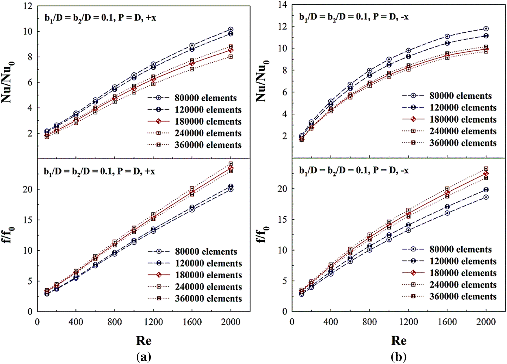
Figure 5: Grid independence or optimum grid selection of b1/D = b2/D = 0.10, and P = D for (a) +x flow path and (b) −x flow path
Based on the numerical validation results, it can be summarized that the computational domain of the RTHX installed with the V-ribs is reliable for predicting of thermal and flow behaviors.
5.1 Fluid Flow Topology and Thermal Behavior
The flow topology within the RTHX is described using streamlines in cross-sectional planes (y-z plane) as depicted in Figs. 6a and 6b for +x and −x fluid-flow directions, respectively, at Re = 800 with various rib height ratios. The rib installation effects the generated vortex flows through the RTHX in all cases. 4–8 main vortex cores are found on each plane depending on the x/D position, b1/D and b2/D. The vortex flows are an important mechanism induced by the ribs. The vortex flow can help with fluid mixing and some segments of the vortex flows may bounce over the tube wall, thus causing thermal boundary layer disturbance (TBLD). The TBLD can increase the convective heat transfer coefficient over the tube wall as well as the heat transfer rate within the RTHX. Both TBLD and better fluid blending are expected when installing ribs in the RTHX.
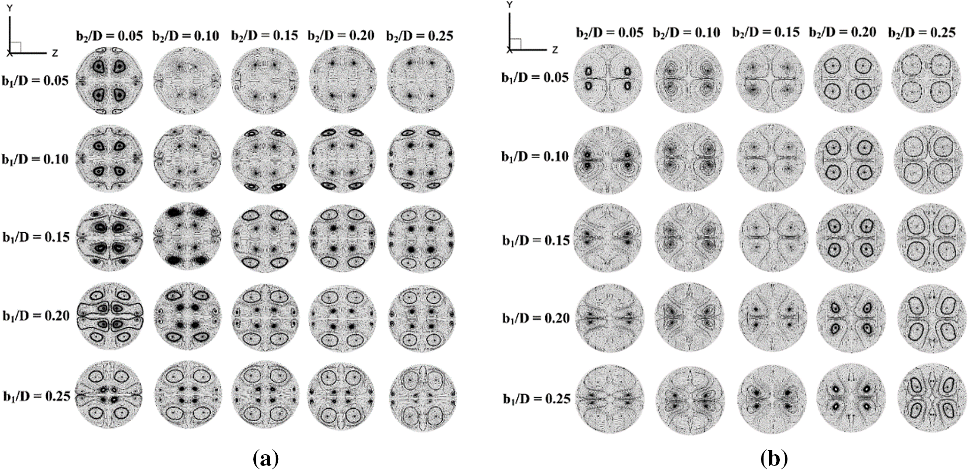
Figure 6: Streamlines in y-z planes at various rib heights of P = D and Re = 800 for (a) +x flow path and (b) −x flow path
Figs. 7a and 7b plot the streamlines on the y-z plane at x/D = 1, 2.25, 3.5, 4.75 and 6 for +x and −x fluid-flow paths, respectively. As revealed in the figures, the vortex flows can be observed through the ribbed tube for both fluid-flow directions, but the structure and the rotation of the flows are not the same.
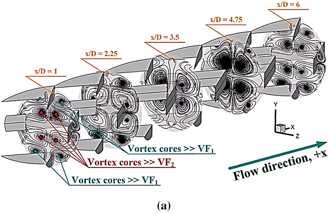
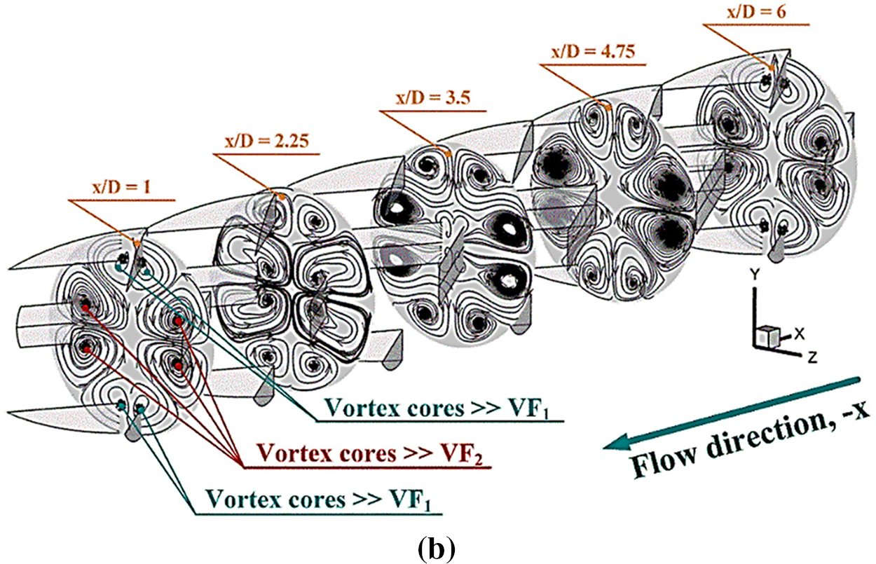
Figure 7: Streamlines in y-z planes of b1/D = 0.15 and b2/D = 0.10, P = D and Re = 600 for (a) +x flow path and (b) −x flow path
As shown in Fig. 8, there are two groups of vortex flows based on their locations. The vortex flows near the upper-lower sections of the y-z planes are called “VF1”, while the vortex flows within the central zone of the planes are called “VF2”. The VF1 are produced by the upper-lower ribs, while the VF2 are created by the middle ribs. Some parts of both VF1 and VF2 close to the tube surface directly disturbs the thermal boundary layer (see Fig. 9). The impinging flows on the tube wall and TBLD can be observed from both +x and −x cases. Focusing on the cross-sectional planes, when the flow direction changes, not only the reverse flow rotation is observed, but different thermal behaviors are also observed due to the difference in the fluid flow structure.
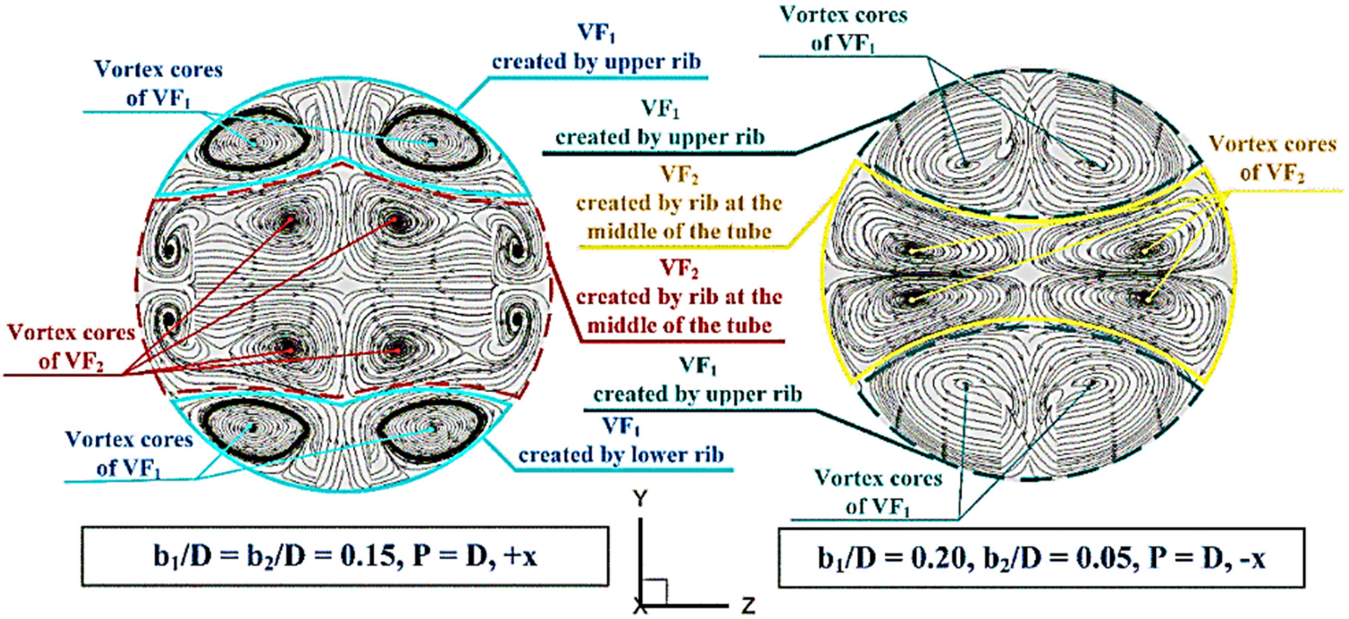
Figure 8: Flow description
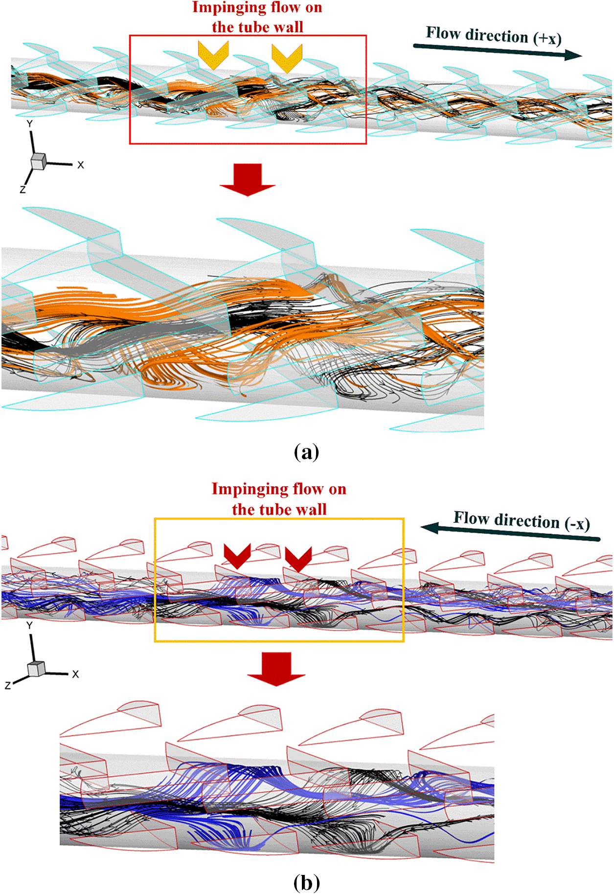
Figure 9: Impinging flow on the tube wall of b1/D = 0.15 and b2/D = 0.10, P = D and Re = 600 for (a) +x flow path and (b) −x flow path
The TBLD in the RTHX can be observed from the temperature contour in y-z planes. The temperature contours in y-z planes are depicted in Figs. 10a and 10b for +x and −x fluid paths, respectively, with various b1/D and b2/D at P = D. In similar conditions of fluid flow and temperature, the blue contours are found at the tube core, while the red contours are observed close to the tube wall in the case of the plain tube with no ribs. With installed ribs inside the RTHX, the vortex flows created by the ribs effectively promote the fluid temperature blending, and the general thermal structure changes. Another observation worth noting is that the red layer close to the tube wall decreases. The decreasing red layer is the TBLD. The change of thermal structure and TBLD are found in all cases. However, the locations of TBLD for various flow directions are varied due to the dissimilar flow structure. The locations in which TBLD are found for both flow directions are presented in Fig. 11.
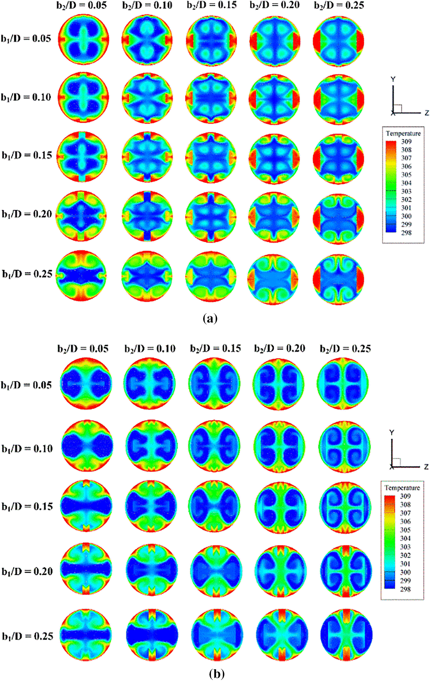
Figure 10: Fluid temperature distributions in y-z planes at various rib heights of P = D and Re = 800 for (a) +x flow path and (b) −x flow path
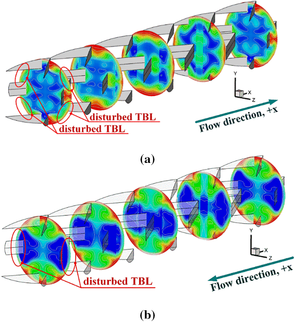
Figure 11: Fluid temperature distributions in y-z planes of b1/D = 0.15 and b2/D = 0.10, P = D and Re = 600 for (a) +x flow path and (b) −x flow path
The local Nusselt number distributions over the tube surface are another plot which indicates the presence of TBLD and impinging stream over the tube wall. Figs. 12a and 12b present local Nusselt number diffusions over the tube surface for +x and −x flow directions, respectively, when P = D with different b1/D and b2/D. In general, it is observed that the installation of ribs leads to the augmented Nusselt number. The red contours of the local Nusselt number mean high heat transfer rate, while the blue contours mean low heat transfer rate. Considering the red contours, the Nusselt number increases when b1/D and b2/D increases for both fluid-flow directions. The reason is that the increasing rib height directly increases the vortex strength. The vortex strength augmentation provides the strength of impinging flow over the tube surface and also results in the same way of the fluid blending. The maximum of the local Nusselt number distributions depends on the position of impinging flow as shown in Fig. 13. For P/D = 1.5 and 2, the air flow configuration and heat transfer mechanism through the ribbed tube are similar to that of P = D.
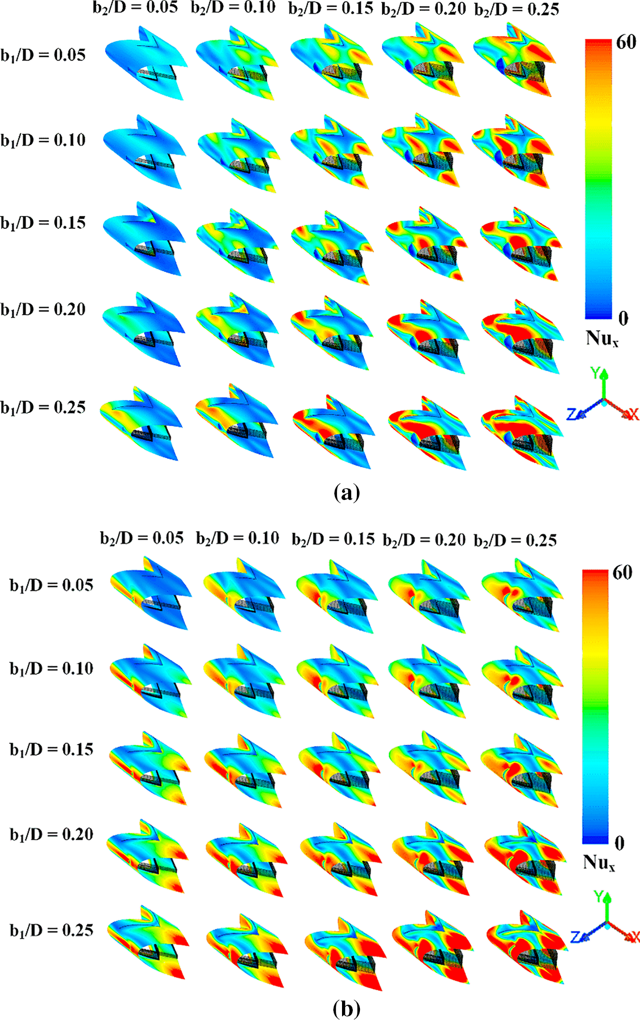
Figure 12: Nux contours in y-z planes at various rib heights of P = D and Re = 800 for (a) +x flow path and (b) −x flow path
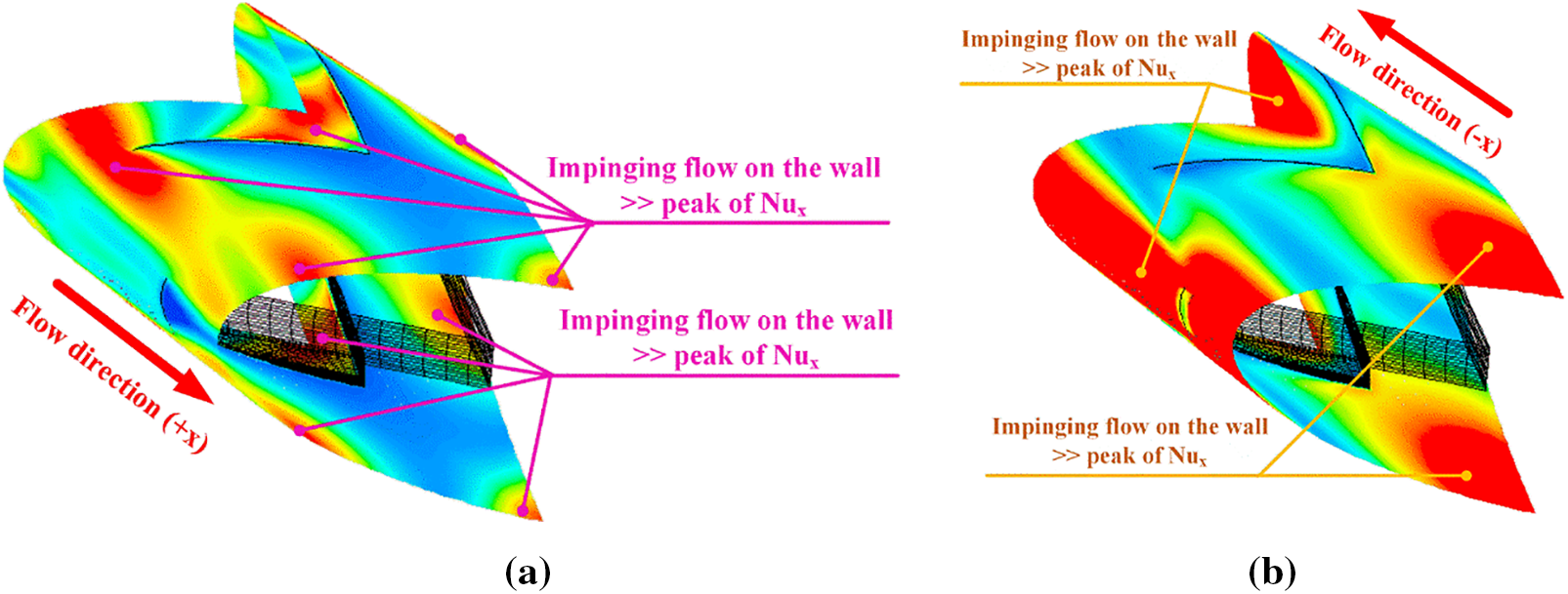
Figure 13: Nux contours in y-z planes of b1/D = 0.15 and b2/D = 0.10, P = D and Re = 600 for (a) +x flow path and (b) −x flow path
The thermal assessments in the ribbed tube are performed by the relative between Nu/Nu0, f/f0 and TEF vs. Re. The relations between Nu/Nu0 and Re with various b1/D and b2/D are plotted in Figs. 14a–14c, respectively, for P = D, 1.5D and 2D. As shown in the figures, the Nu/Nu0 increases with Re for all pitch ratios and also augments with b1/D and b2/D, except for b1/D = 0.25 of P = 1.5D and 2D. The augmentation of Nu/Nu0 is caused by the increase in vortex strength. The ribs installation provides higher heat transfer than that of the general tube without rib for all studied conditions. The Nu/Nu0 of the present work is 1–19, 1–17 and 1–15.5 times greater than the plain-round tube without ribs for P = D, 1.5D and 2D, respectively. The increase in the rib spacing ratio results in a reduction of heat transfer because of the decrease in vortex strength.
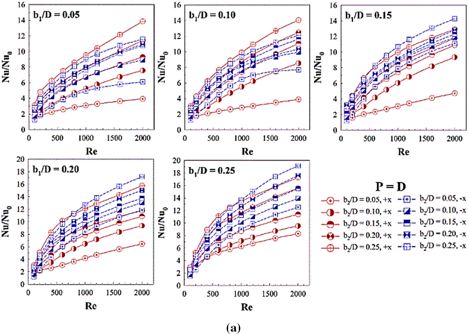
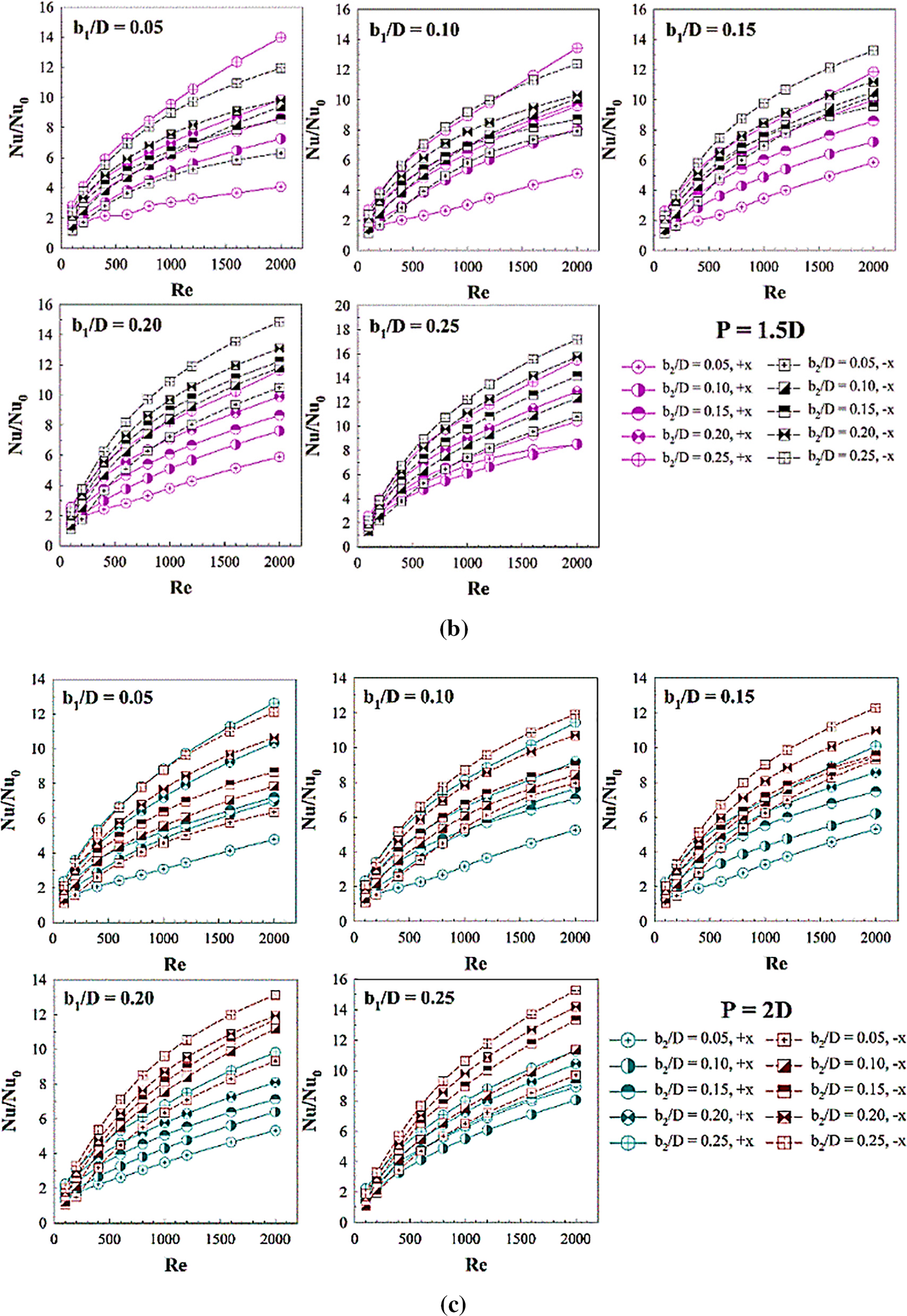
Figure 14: Performance assessment in the RTHX installed with three V-rib sets: Nu/Nu0 vs. Re for (a) P = D, (b) P = 1.5D and (c) P = 2D
The rib installation not only leads to higher heat transfer, but also gives higher pressure loss/drop or friction loss when compared with the general tube. Figs. 15a–15c report the relatives of the f/f0 vs. Re at different b1/D and b2/D for P = D, 1.5D and 2D, respectively. As revealed in the figures, the f/f0 rises when Re, b1/D and b2/D increases for all pitch ratios. The +x flow direction results in similar values of the f/f0 as the −x flow direction. The rib spacing ratio of 1 provides the maximum pressure loss, while the rib spacing ratio of 2 provides the opposite. This means that the augmentation of rib spacing is benefit for the pressure loss reduction of the heat transfer system.
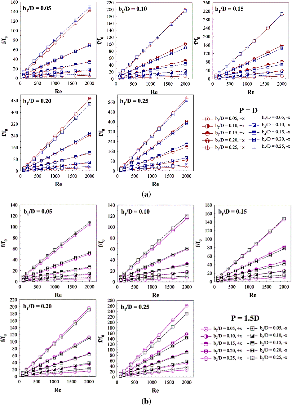
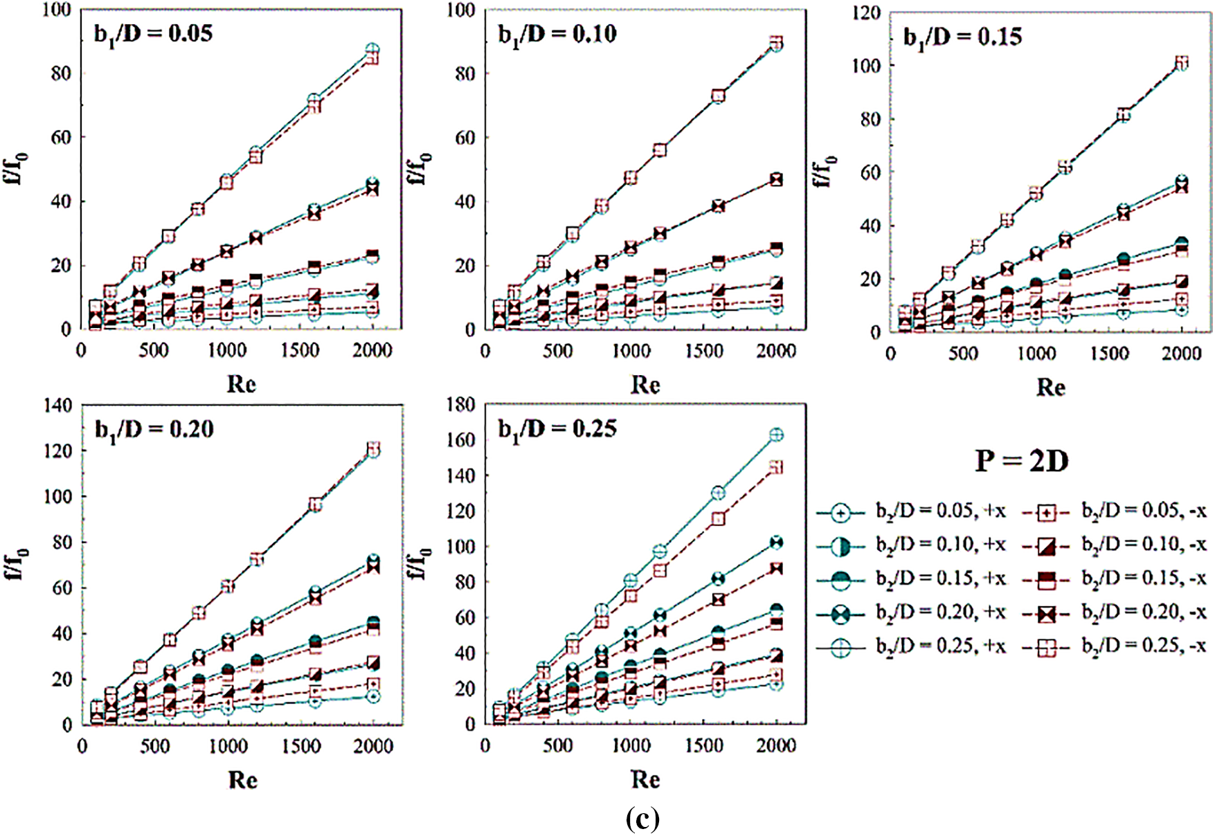
Figure 15: Performance assessment in the RTHX installed with three V-rib sets: f/f0 vs. Re for (a) P = D, (b) P = 1.5D and (c) P = 2D
Ribs bring both higher heat transfer ability and pressure drop. Therefore, the thermal enhancement factor or TEF is selected to describe their advantages. The rib installation in the RTHX provided greater TEF than the general RTHX without ribs for almost all cases. This is revealed in Fig. 16 which plots the relation of the Nu/Nu0 and f/f01/3. The plots are distributed at the upper triangular section. In other words, these plots show the advantages of the rib installation. Figs. 17a–17c plot the TEF vs. Re at dissimilar b1/D and b2/D for P = D, 1.5D and 2D, respectively. In general, the TEF tends to increase when Re increases. The maximum TEF is 4.06, 4.10 and 4.01 for P = D, 1.5D and 2D, respectively, at b1 = 0.15D, b2 = 0.05D and −x fluid direction.
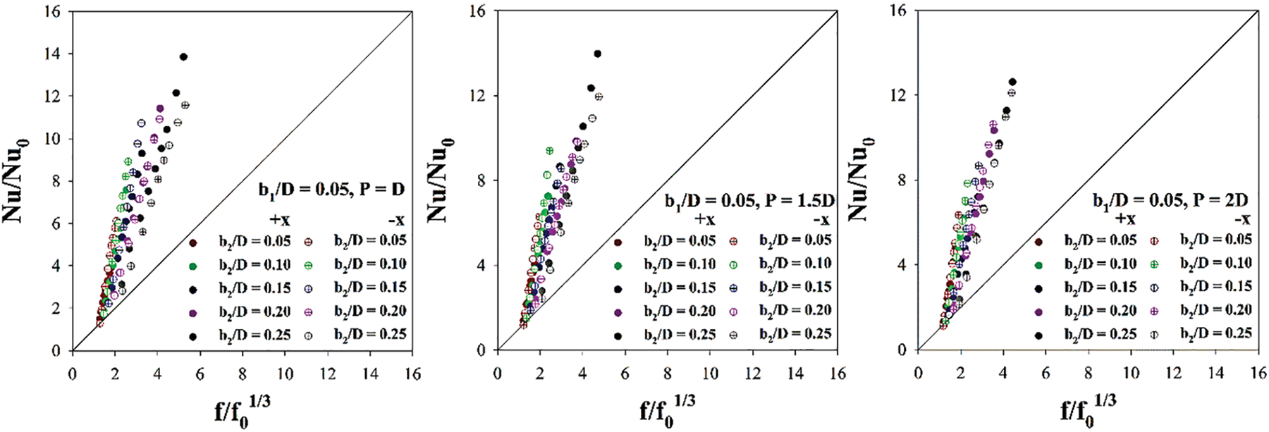
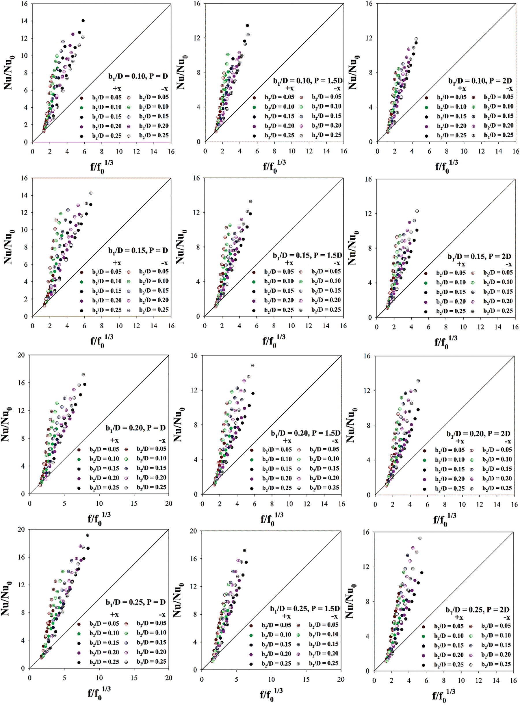
Figure 16: Nu/Nu0 vs. f/f01/3 for various examined cases
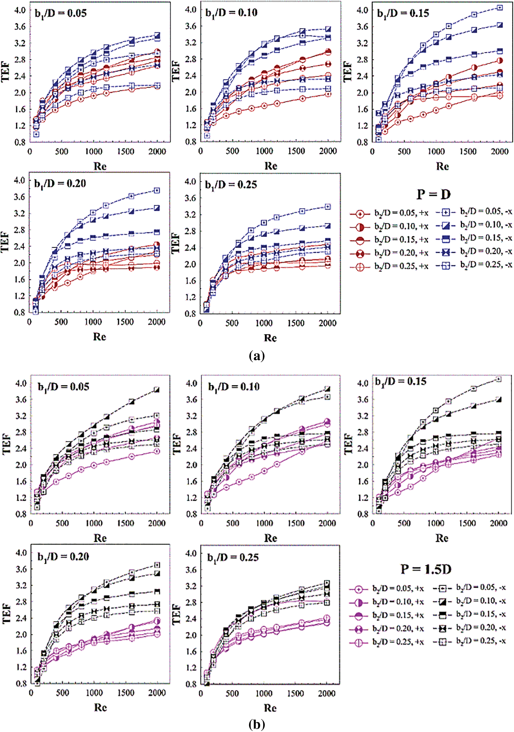
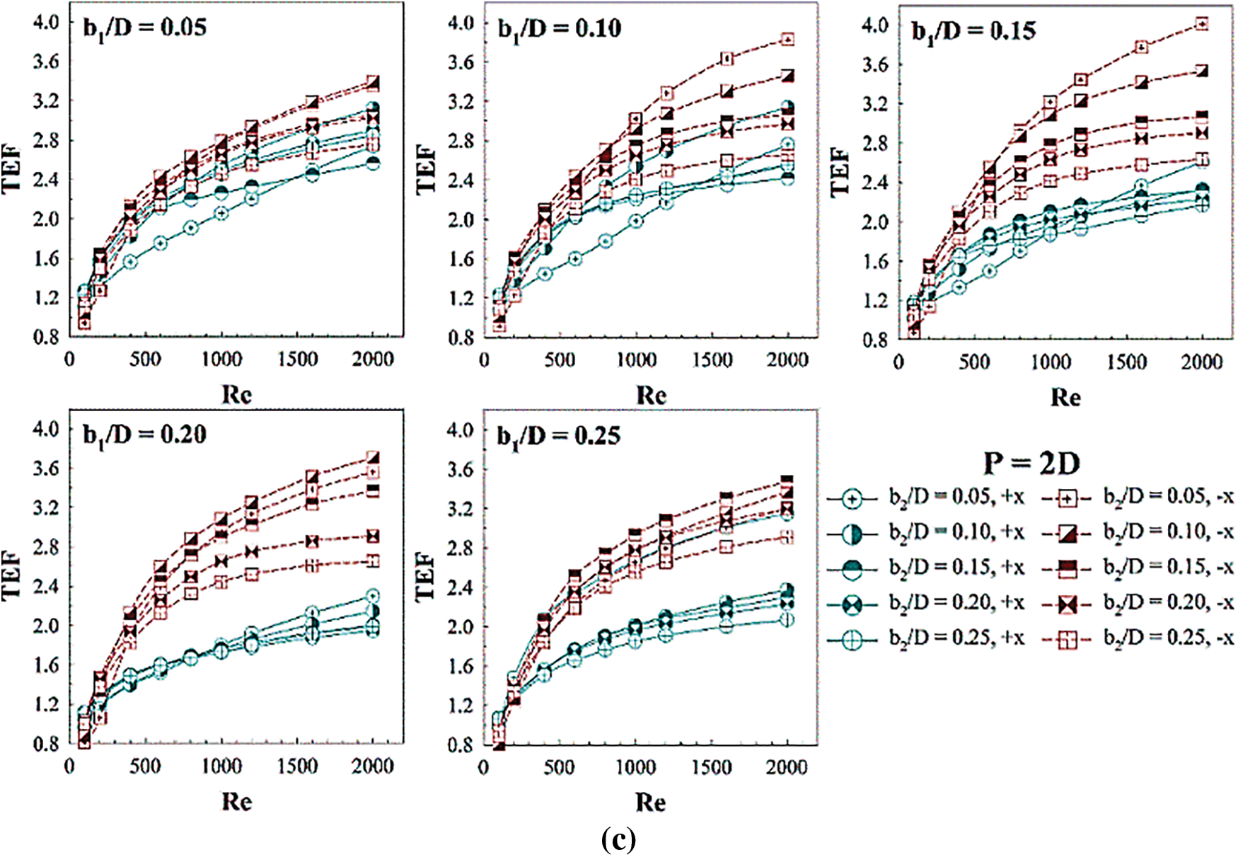
Figure 17: Performance assessment in the RTHX installed with three V-rib sets: TEF vs. Re for (a) P = D, (b) P = 1.5D and (c) P = 2D
Fig. 18 shows the TEF plot at different b1/D and b2/D for P = D, 1.5D and 2D of both flow directions. The figures reveal that the maximum TEF of +x flow direction is found in all pitch distances when b1 is between 0.05–0.10D and 0.05–0.15D for b2. The optimum TEF of −x flow direction for all pitch distances is found in the same condition for both b1 and b2, that is b1 = 0.15D and b2 = 0.05D. The TEF plot can help to design and select the parameters (b1, b2, P and flow direction) of the rib for industrial heating/cooling systems.
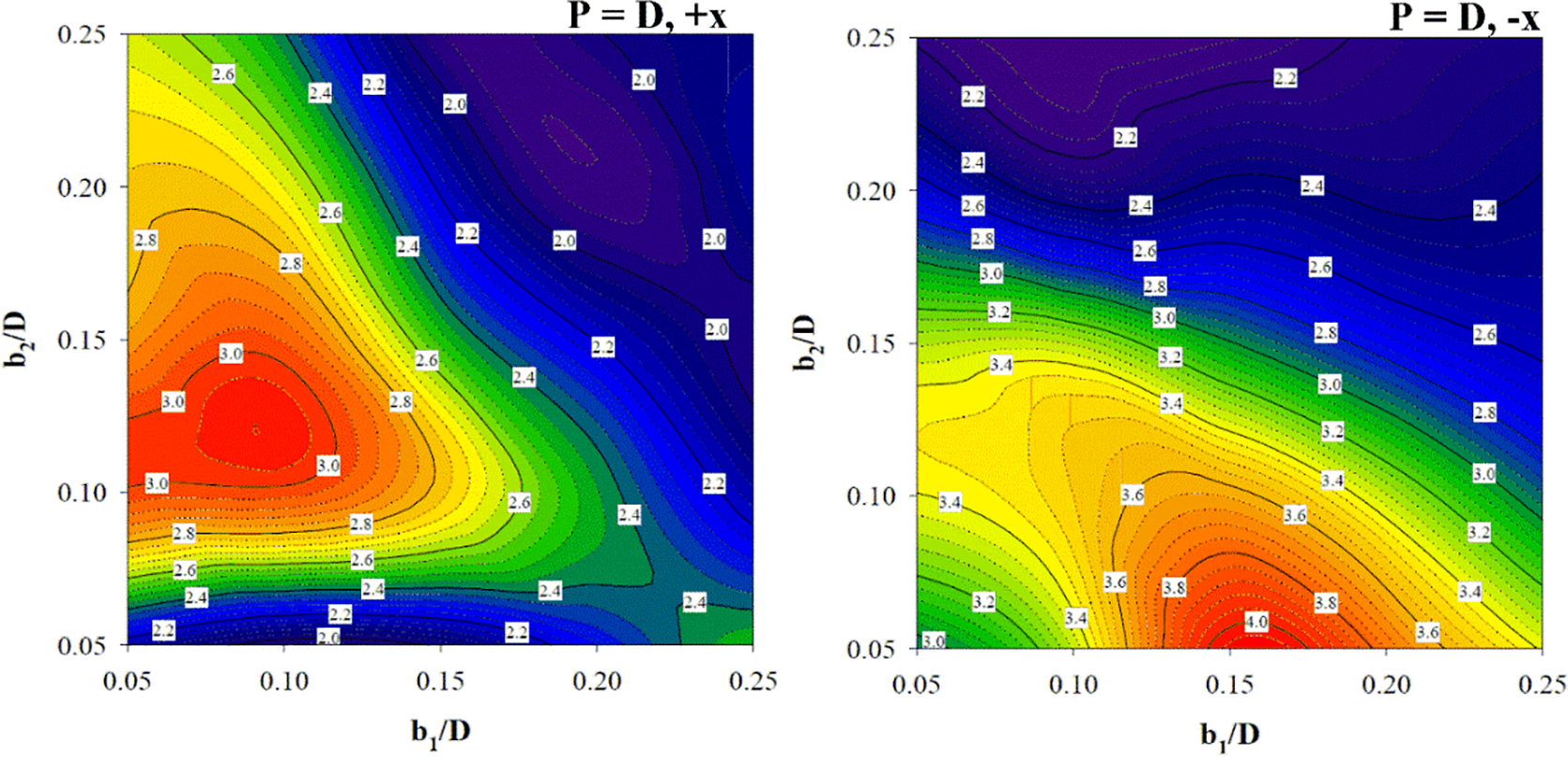
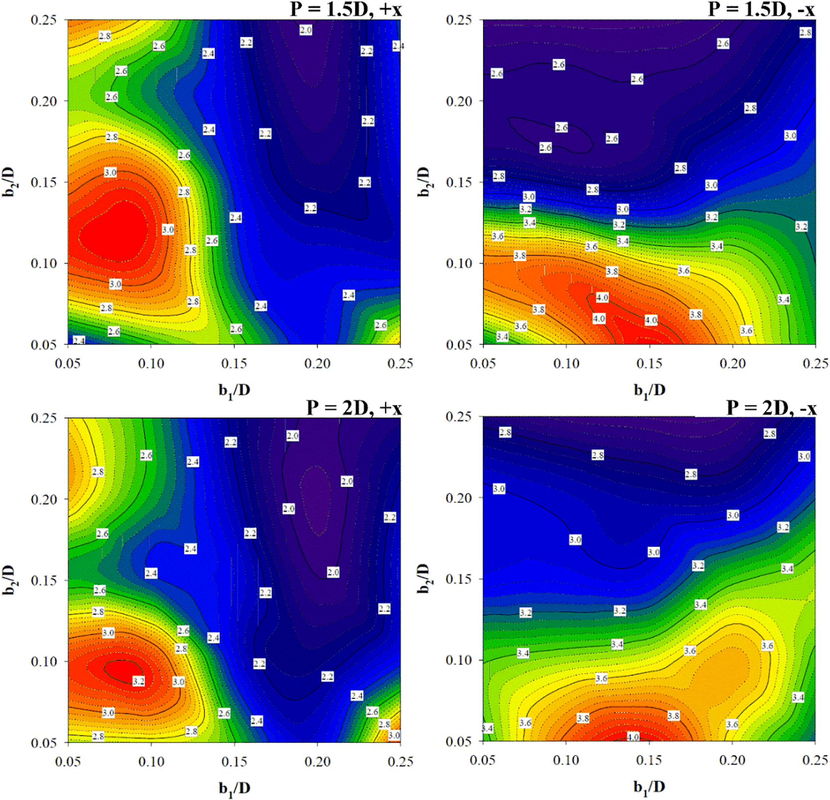
Figure 18: TEF contours in the RTHX installed with three V-rib sets at different b1/D, b2/D, P/D and flow paths
The current numerical outcomes are compared with our earlier publications (Jedsadaratanachai et al. [31], Jedsadaratanachai and Jayranaiwachira [32]). The V-rib turbulators were placed on the tube wall with in-line arrangement (See reference (Jedsadaratanachai et al. [31])) and V-profile ribs were added at the central of the tested tube (along the diameter) (See reference (Jedsadaratanachai and Jayranaiwachira [32])). The comparison of the maximum Nu/Nu0 between the present results and the previous work is shown in Fig. 19. The maximum Nu/Nu0 of the present work is 6.36%– 12.83% and 6.62%– 20.57% for +x and −x fluid-flow ways, respectively, higher than that of the previous work (Jedsadaratanachai et al. [31]). Likewise, it is also 13.62%– 43.14% times higher than that of the other study (Jedsadaratanachai and Jayranaiwachira [32]).
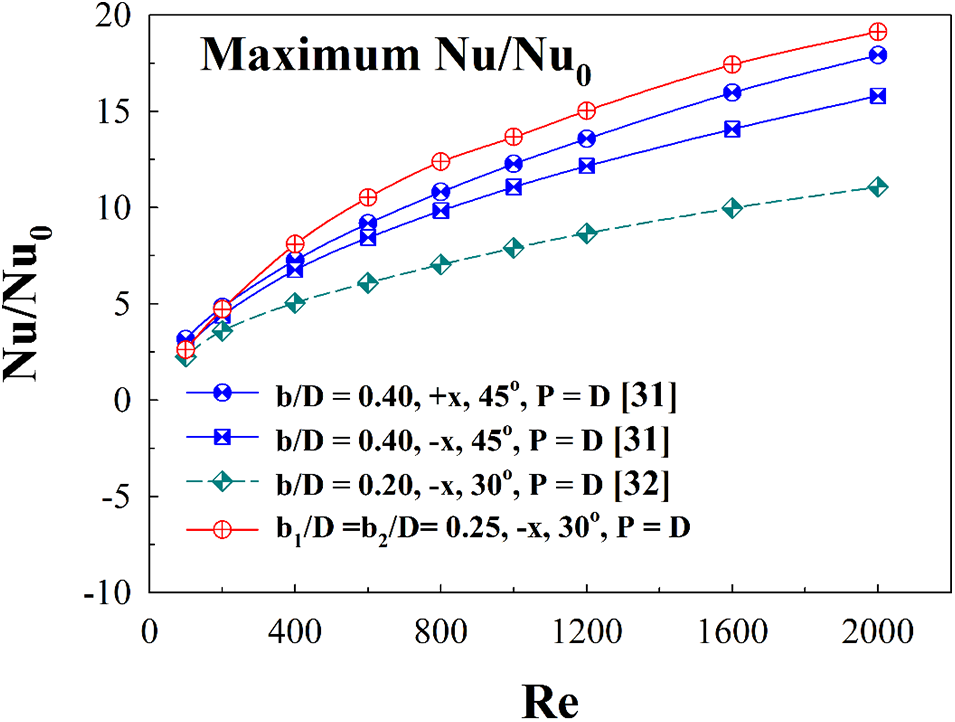
Figure 19: Comparing heat transfer of the present prediction and the published works
The comparison between the present numerical prediction and our previous works (Jedsadaratanachai et al. [31], Jedsadaratanachai and Jayranaiwachira [32]) is also plotted in terms of TEF in Fig. 20. The maximum TEF for all works is selected for the plot. As shown in the figure, the TEF values for all cases follow a similar trend. The best TEF for all cases is observed at the highest Reynolds number (Re = 2000). In almost all cases, the TEF is much higher than the general tube without ribs (or TEF > 1). The present work provides greater TEF than that observed in reference (Jedsadaratanachai and Jayranaiwachira [32]) for all Reynolds numbers. It also provides greater TEF than that observed in reference (Jedsadaratanachai et al. [31]) when Re > 400. The TEF of the present work is found to be better than the TEF of reference (Jedsadaratanachai et al. [31], Jedsadaratanachai and Jayranaiwachira [32]) by 21.89% and 31.60%, respectively, Re = 2000.
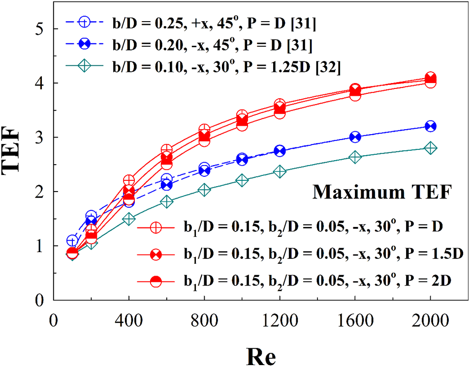
Figure 20: Comparing TEF of the present prediction and the published works
It can be concluded that the three V-rib sets results in greater heat transfer potentiality and thermo-hydraulic performance than the placement of ribs at the tube surface (Jedsadaratanachai et al. [31]) as well as the addition of ribs along the tube diameter (Jedsadaratanachai and Jayranaiwachira [32]). The optimum rib height is a significant point for enhancing heat transfer potency as well as thermo-hydraulic efficiency. The best rib height value may bring the greatest heat-exchanger performance. However, it is important to take into consideration that while enhancing heat transfer, the greater rib height may cause the higher-pressure loss
Simulation of flow topology and thermal behavior within a RTHX equipped with three sets of V-profile ribs is performed in the current research. The two sets of the V-profile ribs are located over the tube surface in the opposite direction (in-line arrangement). Another set of the V-ribs are located at the tube center along the tube diameter. The impacts of rib height (b1/D = 0.05 – 0.25 and b2/D = 0.05 – 0.25) and rib distance (P = D, 1.5D and 2D) on air flow and thermal characteristic are numerically examined under a laminar condition (Re = 100–2000). The fluid-flow directions: +x and −x, are compared. The important consequences of our investigations are concluded as follows.
The rib placement performs expected the following phenomena: higher efficient fluid blending, vortex flow generation, flow impingement and TBLD are important mechanisms which help to increase the forced convective heat transfer, thus leading to an increase in heat transfer. These mechanisms depend on the vortex strength. The strength of the vortex flow and impinging flow increases when augmenting rib height, Reynolds number and decreasing the rib spacing ratio.
The highest heat transfer 19 times greater than that observed in the general tube with no ribs. The optimum TEF for all rib pitch ratios is not much different. The optimum TEF observed for the –x fluid-flow direction is 4.06, 4.10 and 4.01 for P = D, 1.5D and 2D, respectively, at b1 = 0.15D and b2 = 0.05D.
Here are suggested values for each factor. The optimum rib height for this turbulator is b1 of 0.15D and b2 of 0.05D for –x fluid-flow direction and is b1/D = 0.05 – 0.10 and b2/D = 0.05 – 0.15 for +x fluid direction. The suggested rib spacing ratio is P/D = 1 which provides the best Nusselt number.
Acknowledgement: The authors would like to thank Assoc. Prof. Dr. Pongjet Promvonge for suggestions.
Funding Statement: This work is supported by King Mongkut’s Institute of Technology Ladkrabang [2566-02-01-006].
Author Contributions: The authors confirm contribution to the paper as follows: study conception, design, data collection: A. Boonloi; analysis and interpretation of results and draft manuscript preparation: W. Jedsadaratanachai. All authors reviewed the results and approved the final version of the manuscript.
Conflicts of Interest: The authors declare that they have no conflicts of interest to report regarding the present study.
References
1. Iqbal, M. H., Ahmed, N., Ali, M., Qaisrani, M. A., Mahmood, M. et al. (2033). Numerical analysis of a novel solar air heater design with V-ribs and jet cooling. Sustainable Energy Technologies and Assessments, 57(6), 103252. [Google Scholar]
2. Li, Q., Zhu, X., Dong, C., Cao, R., Gu, H. et al. (2023). Investigation of noncircular orifice supporting baffle longitudinal flow heat exchangers. Case Studies in Thermal Engineering, 47(10), 103104. [Google Scholar]
3. Zhang, J., Liu, M., Tang, J., Dong, X., Feng, Y. (2023). Structure optimization and flow field characteristics of baffle-type impinging stream reactor. Chemical Engineering and Processing-Process Intensification, 189, 109386. [Google Scholar]
4. Asgari, B., Hakkaki-Fard, A., Hannani, S. K. (2023). Effect of baffle turbulators on the horizontal solar film evaporator of the humidification-dehumidification desalination system. Thermal Science and Engineering Progress, 42(5), 101888. [Google Scholar]
5. Yuan, M., Liu, G., Zhang, X., Zhang, W., Yang, Y. et al. (2023). Heat transfer enhancement for spiral finned tubes with triangular winglets. International Journal of Heat and Mass Transfer, 205(13), 123918. [Google Scholar]
6. Samsudin, A. N., Tijani, A. S., Abdulrahman, S. T., Kubenthiran, J., Muritala, I. K. (2023). Thermal-hydraulic modeling of heat sink under force convection: Investigating the effect of wings on new designs. Alexandria Engineering Journal, 65, 709–730. [Google Scholar]
7. Derikvand, M., Solari, M. S., Toghraie, D. (2023). Entropy generation and forced convection analysis of ethylene glycol/MWCNTs-Fe3O4 non-Newtonian nanofluid in a wavy microchannel with hydrophobic surfaces. Journal of the Taiwan Institute of Chemical Engineers, 143(1), 104707. [Google Scholar]
8. Singh, V. P., Jain, S., Karn, A., Dwivedi, G., Kumar, A. et al. (2022). Heat transfer and friction factor correlations development for double pass solar air heater artificially roughened with perforated multi-V ribs. Case Studies in Thermal Engineering, 39(3–4), 102461. [Google Scholar]
9. Zhao, J., Li, S., Zhang, X., Sun, M., Song, Y. (2023). Enhanced heat transfer of supercritical n-decane in cooling channels with triangular ribs for regenerative cooling. Applied Thermal Engineering, 218(11), 119369. [Google Scholar]
10. Jiang, G., Gao, J. (2022). Flow and heat transfer performance of the channel with different shaped ribs cooled by mist/steam two-phase flow. Case Studies in Thermal Engineering, 38(2), 102365. [Google Scholar]
11. Zhang, P., Xia, P., Guo, X., Xie, S., Ma, W. (2022). A CFD-adjoint reverse design of transverse rib profile for enhancing thermo-hydraulic performance in the solar air heater. Renewable Energy, 198, 587–601. [Google Scholar]
12. Zhang, P., Rao, Y., Xie, Y., Zhang, M. (2021). Turbulent flow structure and heat transfer mechanisms over surface vortex structures of micro V-shaped ribs and dimples. International Journal of Heat and Mass Transfer, 178(3), 121611. [Google Scholar]
13. Krishnaswamy, K., Sivan, S. (2021). Improvement in thermal hydraulic performance by using continuous V and W-Shaped rib turbulators in gas turbine blade cooling application. Case Studies in Thermal Engineering, 24(3), 100857. [Google Scholar]
14. Jiang, W., Zhao, J., Rao, Z. (2021). Heat transfer performance enhancement of liquid cold plate based on mini V-shaped rib for battery thermal management. Applied Thermal Engineering, 189, 116729. [Google Scholar]
15. Zhu, F., Jing, Q., Xie, Y., Zhang, D. (2022). Numerical investigation on flow and heat transfer characteristics of U-shaped channels with side-wall column ribs. International Communications in Heat and Mass Transfer, 137, 106221. [Google Scholar]
16. Lori, M. S., Vafai, K. (2022). Heat transfer and fluid flow analysis of microchannel heat sinks with periodic vertical porous ribs. Applied Thermal Engineering, 205(4), 118059. [Google Scholar]
17. Kumar, R., Kumar, S., Nadda, R., Kumar, K., Goel, V. (2022). Thermo-hydraulic efficiency and correlation development of an indoor designed jet impingement solar thermal collector roughened with discrete multi-arc ribs. Renewable Energy, 189(237), 1259–1277. [Google Scholar]
18. Bhuvad, S. S., Azad, R., Lanjewar, A. (2022). Thermal performance analysis of apex-up discrete arc ribs solar air heater-an experimental study. Renewable Energy, 185(3), 403–415. [Google Scholar]
19. Sujoy, H. R., Saha, K. (2022). Hydro-thermal characteristics of laminar flow through a square duct having transverse ribs and helical screw-tape inserts. International Communications in Heat and Mass Transfer, 130, 105823. [Google Scholar]
20. Zhao, Z., Luo, L., Qiu, D., Wang, Z., Sundén, B. (2021). On the solar air heater thermal enhancement and flow topology using differently shaped ribs combined with delta-winglet vortex generators. Energy, 224, 119944. [Google Scholar]
21. Chang, S. W., Hsu, C. J. (2022). Effect of internal effusion on aerothermal performance of a three-pass channel roughened by angled ribs and pin-fins with lateral flow exit. International Journal of Heat and Mass Transfer, 198, 123387. [Google Scholar]
22. Qi, D., He, J., Xu, Y., Lin, M., Wang, Q. (2022). Effect of rib diameter on flow boiling heat transfer with staggered rib arrays in a heat sink. Energy, 39, 122323. [Google Scholar]
23. Kumar, B. V., Manikandan, G., Kanna, P. R. (2021). Enhancement of heat transfer in SAH with polygonal and trapezoidal shape of the rib using CFD. Energy, 234(9), 121154. [Google Scholar]
24. Zhao, K., Lin, W., Li, X., Ren, J. (2021). Effect of micro rib on aerothermal dynamic in channel flow. International Journal of Heat and Mass Transfer, 178, 121573. [Google Scholar]
25. Tanda, G., Satta, F. (2021). Heat transfer and friction in a high aspect ratio rectangular channel with angled and intersecting ribs. International Journal of Heat and Mass Transfer, 169(8), 120906. [Google Scholar]
26. Jamshidmofid, M., Bahiraei, M. (2022). Thermohydraulic assessment of a novel hybrid nanofluid containing cobalt oxide-decorated reduced graphene oxide nanocomposite in a microchannel heat sink with sinusoidal cavities and rectangular ribs. International Communications in Heat and Mass Transfer, 131, 105769. [Google Scholar]
27. Gill, R. S., Hans, V. S., Singh, R. P. (2021). Optimization of artificial roughness parameters in a solar air heater duct roughened with hybrid ribs. Applied Thermal Engineering, 191(2), 116871. [Google Scholar]
28. Dong, P., Xie, G., Ni, M. (2021). Improved energy performance of a PEM fuel cell by introducing discontinuous S-shaped and crescent ribs into flowing channels. Energy, 222(4), 119920. [Google Scholar]
29. Liu, J., Hussain, S., Wang, W., Xie, G., Sundén, B. (2021). Experimental and numerical investigations of heat transfer and fluid flow in a rectangular channel with perforated ribs. International Communications in Heat and Mass Transfer, 121, 105083. [Google Scholar]
30. Cengel, Y. A., Ghajar, A. J. (2015). Heat and mass transfer: Fundamentals & applications. In: SI units, Fifth edition. McGraw-Hill Education. [Google Scholar]
31. Jedsadaratanachai, W., Jayranaiwachira, N., Promvonge, P. (2015). 3D numerical study on flow structure and heat transfer in a circular tube with V-baffles. Chinese Journal of Chemical Engineering, 23(2), 342–349. [Google Scholar]
32. Jedsadaratanachai, W., Jayranaiwachira, N. (2014). Effect of pitch to height ratio on flow visualization, heat transfer, and thermal performance in a round tube with upstream RWVG. Advances in Mechanical Engineering, 6, 471720. [Google Scholar]
Cite This Article
 Copyright © 2023 The Author(s). Published by Tech Science Press.
This work is licensed under a Creative Commons Attribution 4.0 International License , which permits unrestricted use, distribution, and reproduction in any medium, provided the original work is properly cited.
 Downloads
 Citation Tools