
 Submit a Paper
 Propose a Special lssue
 Open Access
ARTICLE

Heat Recovery from Automotive Exhaust Using Heat Pipes with Limited Fluid Charge
Department of Engineering Technology, Texas State University, San Marcos, 78666, USA
* Corresponding Author: Bin Xiao. Email:
(This article belongs to the Special Issue: Passive Heat Transfer Enhancement for Single Phase and Multi-Phase Flows)
Frontiers in Heat and Mass Transfer 2024, 22(1), 35-48. https://doi.org/10.32604/fhmt.2024.048039
Received 26 November 2023; Accepted 25 January 2024; Issue published 21 March 2024
 View Full Text
 Download PDF
Abstract
Experiments were conducted in this study to examine the thermal performance of a thermosyphon, made from Inconel alloy 625, could recover waste heat from automobile exhaust using a limited amount of fluid. The thermosyphon has an outer diameter of 27 mm, a thickness of 2.6 mm, and an overall length of 483 mm. The study involved directing exhaust gas onto the evaporator. This length includes a 180-mm evaporator, a 70-mm adiabatic section, a 223-mm condenser, and a 97-mm finned exchanger. The study examined the thermal performance of the thermosyphon under exhaust flow rates ranging from 0–10 g/sec and temperatures varying from 300°C–900°C. The influence of three parameters—inclination angle (5°–45°), water mass (2–5.3 g), and the quantity of non-condensable gas Argon (0–0.6 g)—was investigated to assess their impacts on the thermosyphon’s thermal efficiency. The experimental findings revealed that with 3 g of water and 0.0564 g of argon in the thermosyphon, the condenser reached its highest temperature at around 200°C. The ideal fuel loading rate for the thermosyphon falls between 0.2 and 0.7 g/s. Moreover, as inclination angles rise, outer wall temperatures of the thermosyphon increase. This is attributed to the explicit expansion of the effective heating area within the evaporation section, coupled with an amplified gravitational component of the water flux. Additionally, an upsurge in the quantity of non-condensable gas (NCG) can mitigate temperature gradients on the outer wall, resulting in a decline in the thermosyphon’s performance. The insulation applied to the adiabatic section demonstrated efficacy in augmenting temperature gradients on the outer wall, thereby improving the overall performance of the thermosyphon. As the water charge within the thermosyphon increases, there is a corresponding rise in heat transfer rates both from the exhaust to the thermosyphon and from the thermosyphon to the fuel.Keywords
A thermosyphon is a heat transfer device that utilizes the phase transition of a working fluid, such as water, to transfer heat from the evaporator to the condenser without requiring a wick [1]. In contrast to conventional heat pipes, a thermosyphon relies on the inherent circulation of its working fluid within a closed loop for heat transfer. The working fluid is first vaporized at the evaporator, induced by the input of heat. The vaporized fluid then moves toward the cooler condenser, where it releases its latent heat of vaporization, undergoing condensation back into a liquid state. Subsequently, the condensed liquid returns to the evaporator via gravitational forces, establishing a continuous cycle of vaporization, condensation, and fluid circulation. Therefore, the primary heat transfer mechanism in a thermosyphon is driven gravity and the phase transition of the working fluid. Renowned for its simple design, eco-friendly operation, and effective heat transfer abilities, thermosyphon technology has found extensive applications in various products. These applications span electronics cooling systems, solar energy systems, refrigeration systems, and HVAC (Heating, Ventilation, and Air Conditioning) systems [2–7].
Industrial waste heat refers to the energy produced in industrial processes that is not utilized for practical purposes and is instead discarded or released into the environment [8]. Utilizing diverse waste heat recovery technologies including heat pipes allows for the extraction of valuable energy sources, leading to a reduction in overall energy consumption [9]. A thermosyphon can be utilized to recover waste heat from exhaust gas to usable energy for preheating inflow fuel or electricity conversion, thereby increasing the overall energy efficiency of a car. The effectiveness of the thermosyphon as a heat recovery system depends on various factors, such as the temperature of the exhaust gas, the flow rate of the liquid, and the size of the thermosyphon.
Past research has explored diverse facets of thermosyphon or heat pipe as a heat recovery systems, delving into areas such as design, experimental testing, and optimization, offering valuable insights into the potential advantages and limitations of employing thermosyphon technology for waste heat recovery across various applications [10–15]. Through theoretical analyses, Yerne et al. [10] evaluated a single thermosyphon’s capacity to recover heat from simulated diesel engine exhaust conditions. The findings indicated that the thermosyphon could achieve an effectiveness of over 50% under all considered conditions. Notably, with a reduced inlet hot air velocity to 1 m/s at a temperature of 350°C, the thermosyphon’s effectiveness increased significantly to 88%. Conversely, the thermosyphon’s effectiveness was at its lowest when the heat capacity rate of the hot and cold fluids was equal. Ali et al. [11] conducted experiments and calculations to investigate the heat transfer performance of a thermosyphon using two refrigerants (R22 and R407c) at various temperatures, airflow rates, filling levels, and heat capacity ratios. Additionally, they developed and validated a mathematical model using MATLAB for the thermosyphon’s heat transfer performance. The results indicated a direct proportionality between the heat transfer rate and the evaporator inlet-air temperature and flow rate. Notably, the heat transfer performance improved with higher temperatures and airflow rates, reaching optimal levels with 100% filling and a heat capacity ratio of 1.5. Furthermore, the effectiveness increased with higher temperatures and lower airflow rates, with R22 demonstrating superior effectiveness compared to R407c. Cao et al. [12] created a heat pipe-assisted thermoelectric generator for recovering waste heat from automobile exhaust after optimizing the depth and angle of the heat pipe. Experimental results reveal that the power output of the HP-TEG is most favorable under high exhaust temperature, increased cold water flow rate, and higher mass flow rate. The maximum open circuit voltage from 36 thermoelectric modules (TEMs) measures 81.09 V. With optimized conditions, the corresponding power output and pressure drop are 13.08 W and 1657 Pa, respectively, resulting in an enhanced thermoelectric power generation efficiency of the HP-TEG at 2.58%. Wang et al. [13] developed a special-shaped heat pipe suitable for absorbing the waste heat of the aircraft engine named RB211-535E4 according to the structural characteristics of the internal and external ducts of the aeroengine. The numerical findings suggest that the temperature distribution in the special-shaped heat pipe is significantly superior to that in a traditional heat pipe. Among the special-shaped heat pipes, those with an R (radius) of 0.6 mm exhibited the most effective heat transfer. Notably, the special-shaped heat pipe with an R of 0.4 mm demonstrated the shortest start-up time and the lowest start-up temperature. Hong et al. [14] devised an innovative thermal enhancement approach, combining a spiral corrugated tube (SCT) with multiple twisted tapes (TTs) for liquid-gas heat exchange in a typical waste heat recovery setting. Through numerical investigations, they scrutinized the impact of the number of twisted tapes (TTs), transverse space ratios (S/D), and longitudinal perforation length ratios (L/D) on turbulent heat transfer and fluid flow characteristics within the tubular system. Introducing simple perforations on the surface of the quadruple TTs resulted in a substantial improvement of the maximum thermal performance evaluation index (η) by approximately 7.9%. The SCT with S/D = 0.152 and L/D = 0.348 achieved a maximum η of 1.23. Wang et al. [15] designed a Heat Pipe Thermoelectric Generator (HPTEG) as a waste heat recovery system for achieving both passive thermal management and electricity generation. The evaluation of heat transfer performance in heat pipes involves introducing the concept of effective thermal conductivity. At a heat pipe temperature of 630°C, the effective thermal conductivity peaks at 35831 W/(m·K), nearly 100 times greater than that of copper. In the thermoelectric generator (TEG), the effective thermal conductivity decreases as the TEG’s hot side temperature rises if the temperature remains below 200°C. Upon reaching 200°C, the effective thermal conductivity stabilizes at approximately 3 W·K−1·m−1. Karana et al. [16] studied the performance of the exhaust heat exchanger with twisted ribs for the six different operating points of the diesel engine. The study concentrated on three geometric aspects of twisted tape: pitch ratio, twist ratio, and tilt angle. The findings indicated that compared to a smooth surface system, employing twisted ribs in the system led to a higher net power output. Additionally, a comparison of fuel consumption between the suggested system and a frequently used alternator demonstrated the potential to enhance Brake Specific Fuel Consumption (BSFC) by around 0.65%.
Internal combustion engines (ICEs) have limitations in efficiently converting chemical energy into mechanical energy, leading to a significant amount of wasted energy being released as heat in the exhaust. To enhance fuel efficiency and mitigate emissions, one approach is to recover the waste heat by employing thermosyphons to preheat the inflow fuel before it enters the combustion engine. By recovering and utilizing waste heat, the overall efficiency of the vehicle’s combustion process is increased. This means that a higher percentage of the energy from the fuel is converted into useful work, thereby reducing the required amount of fuel for equivalent performance levels and mitigating carbon dioxide (CO2) emissions. In this study, experiments were conducted to examine the thermal performance of a thermosyphon designed for recovering waste heat from automobile exhaust. The study aimed to assess how effectively the thermosyphon could operate in utilizing a limited amount of fluid charge.
Fig. 1a illustrates the setup of the heat recovery system, utilizing a thermosyphon to preheat fuel before injecting it into the combustion engine. The exhaust gas was directed onto the evaporator end cap, with a flow rate ranging from 0 to 10 g/sec and temperatures between 300°C and 900°C. Fuel preheating on the condenser end cap reached approximately 160°C, with a flow rate of 0.2 to 2 g/sec at an ambient temperature of 20°C. This preheating process puts the fuel in a supercritical state, promoting swift and clean combustion while reducing the fuel consumption needed to power the vehicle, ultimately enhancing fuel efficiency.
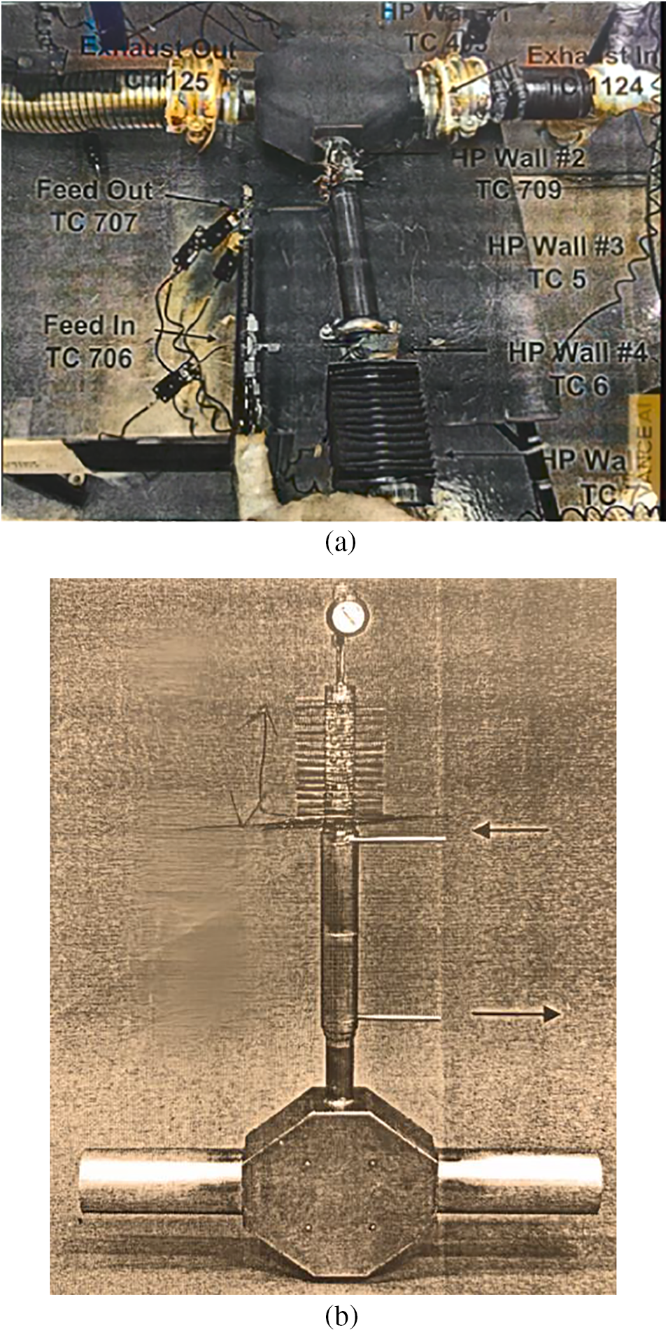
Figure 1: Schematic diagrams of (a) the exhaust heat recovery system and (b) the thermosyphon
Temperature measurements were conducted using K-Type thermocouples at various positions along the thermosyphon’s length, starting from the exhaust end cap. These positions included the ends of evaporator (exhaust heating section), adiabatic section, condenser (fuel heating section), and the heat exchange section with fins on the outer wall of the thermosyphon. The wires linked to one end of the thermocouples were affixed to the pipe surface using high-temperature epoxy. Simultaneously, the wires attached to the opposite end of the thermocouples were connected to the relevant input channels on the Data Acquisition (DAQ) system (National Instruments TC-2095/SCXI-1100) to enable real-time monitoring of temperature measurements and the retrieval of logged data for subsequent analysis. The DAQ system gathered data every 0.5 s and displayed it on the computer connected to the acquisition system. The uncertainty of the experimental setup for temperature measurements was ±0.1°C. To minimize measurement errors, the same test was repeated multiple times, typically between 3 to 5 repetitions. This repetitive testing aimed to reduce random or systematic errors, enhancing the overall reliability and accuracy of the obtained measurements. The average data from the repeated experiments and standard deviations, represented by error bars in the figures, were displayed to provide clear and concise illustrations of the experimental results.
Fig. 1b illustrates the thermosyphon employed in the heat recovery system. The thermosyphon was initially cleaned to ensure thorough wetting of the inner surfaces with water. Subsequently, the thermosyphon was connected to a water container and a rotary vacuum pump through a three-way valve, and the pump was used to eliminate air from the thermosyphon. To prevent high pressure and temperature in the vapor chamber, which is the evaporator section of the thermosyphon, a controlled amount of water was added to the thermosyphon as the working fluid by adjusting the three-way valve, ensuring that nearly all the water would vaporize during operation. Argon, acting as a non-condensable gas (NCG), was blended with the water. The thermosyphon was then sealed upon filling to uphold the intended operating conditions. The presence of NCG in the thermosyphon raises the total pressure because NCG does not condense like the working fluid, leading to a rise in the saturation temperature of the working fluid. This increase can reduce the temperature difference between the hot and cold ends of the heat pipe, thereby affecting the temperature gradient necessary for heat transfer and undermining the efficiency of heat transfer within the heat pipe. Fins were welded to the condenser end cap to augment the surface area and induce turbulence, promoting more efficient heat dissipation.
The thermosyphon is made from Inconel alloy 625, chosen for its robust thermal-fatigue strength and outstanding corrosion resistance. In this study, the thermosyphon is characterized by the following dimensions: a diameter of 27 mm, a thickness of 2.6 mm, and an overall length of 580 mm. This length encompasses a 180-mm evaporator, a 70-mm adiabatic section, a 223-mm condenser, and a 97-mm finned exchanger.
The thermal performance of the thermosyphon was examined by studying the impact of different design parameters. These included the inclination angle (ranging from 5° to 45°), insulation, the amount of non-condensable gas (Argon) (ranging from 0.0564 to 0.6 g), water charge (ranging from 2 to 5.3 g), and fuel loading rate (ranging from 0.2 to 2 g/s). The baseline operating conditions are tabulated in Table 1.

3.1 Effect of Inclination Angle
The inclination angle in a thermosyphon, as depicted in Fig. 2, refers to the angle at which the heat exchanger or the entire thermosyphon loop is tilted with respect to the horizontal plane. The inclination angle of a thermosyphon plays a significant role in influencing the performance of the thermosyphon by affecting the gravitational forces acting on the working fluid within the thermosyphon under normal driving conditions.
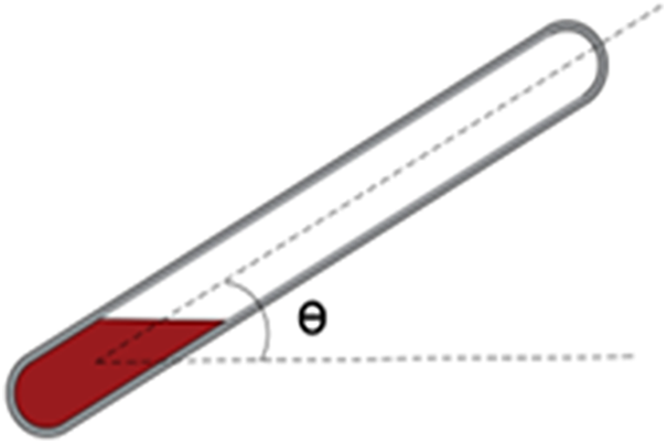
Figure 2: Inclination angle of a thermosyphon
In the experiments designed to evaluate the influence of the inclination angle on the thermosyphon’s performance under normal driving conditions, the thermosyphon was loaded with 4.8 g of water and 0.6 g of Argon. Throughout the experiments, a consistent exhaust flow rate of 7.8 g/s was maintained, and the inflow temperature was set at 350°C.
Fig. 3a shows the outer wall temperatures of the thermosyphon at different inclination angles with no fuel loading, while Fig. 3b displays the outer wall temperatures of the thermosyphon at various inclination angles with fuel loading at a flow rate of 2 g/s. During the experiments, a valve is employed to control fuel flow prior to its entry into the tubes connected to the thermosyphon for preheating purposes. When the valve is switched off, there is no fuel loading, and the fuel flows bypass the tubes on the thermosyphon, entering the combustion chamber directly without preheating. On the other hand, when the valve is turned on, the fuel is allowed to flow into the tubes for preheating before entering the combustion chamber. As can be seen from both Figs. 3a and 3b, whether with or without fuel loading, the temperature at the end cap increases when the inclination angle rises, because increasing the inclination angle can obviously expand the actual heating area of the evaporation section of the thermosyphon and augment the gravitational component of the water flux. When comparing Figs. 3a to 3b, it becomes apparent that the introduction of fuel loading markedly reduces the temperature at diverse locations and under different inclination angles. Additionally, the presence of fuel loading significantly intensifies temperature decrease gradients along the length of the thermosyphon. This suggests that the heat absorption from the thermosyphon by the fuel is considerably higher than that by the air. The observation from Fig. 3b indicates that the temperature at the end cap decreases with an increase in the inclination angle. This trend is attributed to the higher angle, which enlarges the heating area of the evaporation section, facilitating the return of more water and resulting in a lower temperature at the end cap. The findings from Fig. 3 lead to the conclusion that both the presence of fuel loading and the increase in inclination angle contribute to an enhanced heat transfer rate, thereby improving the performance of the thermosyphon. As can be seen from both Figs. 3a and 3b, almost all surface of the evaporator section experiences overheating, leading to the occurrence of dry-out phenomena attributed to an excessive water charge in the thermosyphon. Subsequent sections, particularly 3.4 (effect of water charge), will delve into explanations on achieving an optimal water charge to prevent dry-out phenomena and uphold a high heat transfer coefficient.
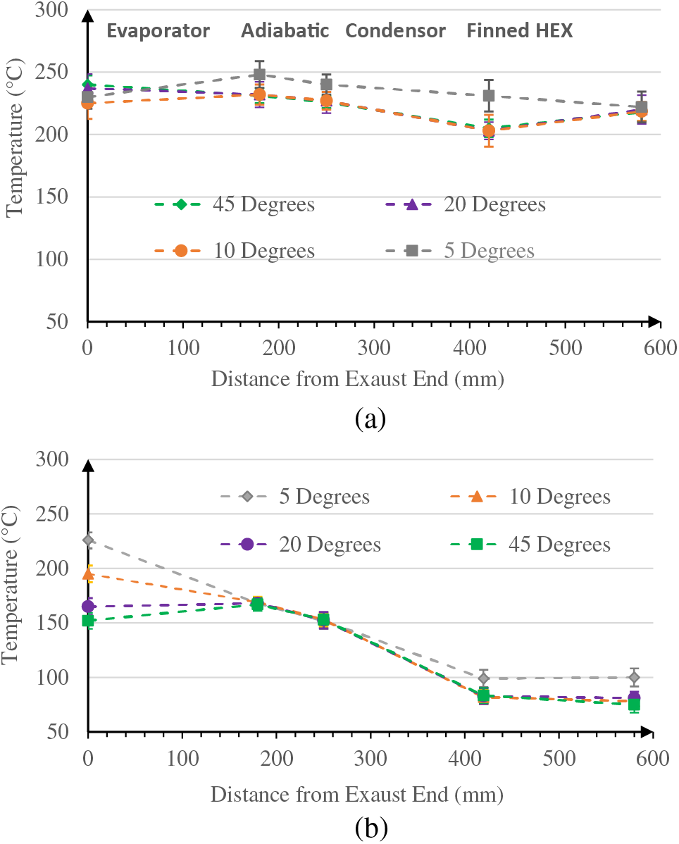
Figure 3: Temperature profiles at various angles (a) without fuel loading and (b) with fuel loading of 2 g/s
Fig. 4 illustrates the heat duty of the thermosyphon under various inclination angles, considering two different exhaust inflow temperatures, both with and without fuel loading. The term “heat duty” here denotes the amount of heat flux transferred to the fuel as it traverses condenser section of the thermosyphon, from the feed-in inlet to the feed-out outlet. The heat duty of the thermosyphon Q ˙˙ can be calculated by:
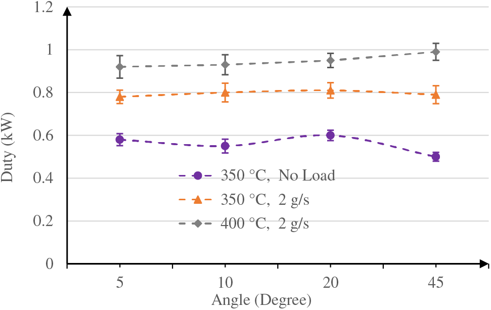
Figure 4: Heat duty of the thermosyphon at various inclination angles and exhaust inflow temperatures with/without fuel loading
where
In the experiments conducted to assess the impact of the inclination angle on the heat duty of the thermosyphon, the thermosyphon was charged with 4.8 g of water and 0.6 g of Argon, while sustaining a consistent exhaust flow rate of 7.8 g/s. As can be seen in Fig. 4, heat duty of the thermosyphon rises with an increase in exhaust inflow temperature. According to Eq. (1), as the inflow temperature of the exhaust increases, the mass flow rate of the evaporated water increases, leading to a rise in the heat duty of the thermosyphon. This indicates that more heat is dissipated from the condenser to the fuel, thereby improving the performance of the thermosyphon.
The findings also highlight that, compared to the thermosyphon operating without fuel loading, the heat duty of the thermosyphon experiences an increase when fuel is loaded. This is attributed to the significantly higher specific heat of the fuel in contrast to that of air, facilitating enhanced heat dissipation to the fuel from the thermosyphon. Consequently, with fuel loading, there is a notable increase in the heat duty of the thermosyphon, contributing to an overall improvement in performance.
In heat pipe applications, a small amount of non-condensable gas is intentionally added during the manufacturing process to prevent the formation of a vacuum. However, the expansion of non-condensable gas, i.e., Argon, at the vapor-gas interface, which is necessary to maintain pressure equilibrium and reduce temperature fluctuations, can have a negative effect on the performance of a thermosyphon.
Fig. 5 illustrates the outer wall temperatures under various Argon loadings with and without fuel loading. In the experiments designed to evaluate the influence of non-condensable gas (NCG) amount on the thermosyphon’s performance, the thermosyphon was filled with 2.75 g of water and 0.6 g of Argon. The exhaust flow rate was fixed at 7.8 g/s, and the inflow temperature was held constant at 350°C.
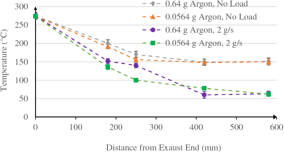
Figure 5: Temperature profiles under different NCG amounts
The results revealed that, regardless of fuel loading, an augmentation in the NCG amount can reduce temperature gradients under a constant exhaust heat loading condition. This observation indicates that NCG does not undergo condensation like water. Consequently, the total pressure of vapor and NCG increases, leading to a rise in the saturation temperature of water. As shown in the results, the temperature gradient necessary for heat transfer is reduced because the saturation temperature of water is increased, ultimately undermining the performance of the thermosyphon.
The results shown in Fig. 5 also revealed the substantial positive influence of fuel loading on the thermosyphon’s performance. The heightened specific thermal conductivity of the fuel, in comparison to the empty air, enhances the heat dissipation from the condenser to the preheating fuel. This enhancement leads to increased temperature decrease gradients, thereby enhancing the overall performance of the thermosyphon.
Applying insulation to the surface of a thermosyphon is a tactic aimed at maximizing its thermal performance. This approach minimizes heat loss to the surrounding, preserves temperature differences between the evaporator and the condenser, and promotes efficient heat transfer within the thermosyphon. The insulation is important in applications where heat management and energy efficiency are critical considerations. Heat loss of the thermosyphon under different insulation conditions
where
Fig. 6 illustrates the effect of insulation on the wall temperatures of the thermosyphon. In the experiments conducted to evaluate the influence of insulation on the thermosyphon’s performance, the thermosyphon was charged with 3.0 g of water and 0.0564 g of Argon to achieve a maximum fuel temperature of 200°C. The exhaust flow rate was set at 7.8 g/s, and the inflow temperature was 507°C.
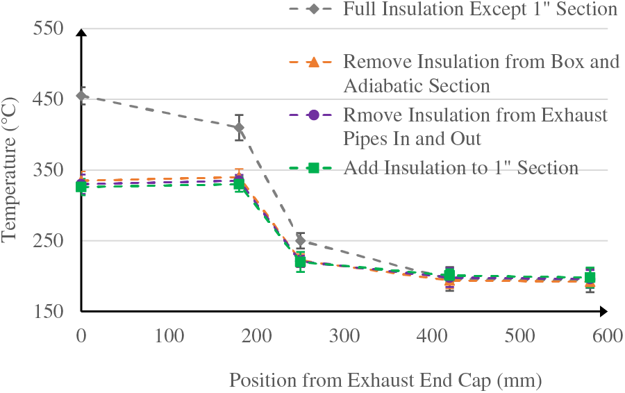
Figure 6: Temperature profiles under different insulation conditions
The results shown in Fig. 6 indicate that the application of insulation to the exhaust pipes and the 1” section from the evaporator end cap did not result in significant changes in wall temperatures. In contrast, insulating the adiabatic section and the exhaust box resulted in elevated temperatures and temperature gradients in both the evaporation section and adiabatic section, consequently enhancing the thermosyphon’s performance. Insulating both the exhaust box and the adiabatic section reduced heat loss to 0.296 kW. In contrast, without insulation on these components, the heat loss was higher at 0.484 kW. The insulation of the adiabatic section and the exhaust box amplifies temperature gradients within the thermosyphon, consequently generating higher pressure gradients. This heightened pressure gradient propels fluid flow from the evaporator to the condenser and back. As a result, the augmented pressure gradients contribute to enhanced heat transfer rates, ultimately bolstering the overall performance of the thermosyphon.
The amount of working fluid, such as water, within the thermosyphon is a crucial design parameter. Insufficient water filling may result in a dry out limit, where the fluid fails to adequately cover the entire internal surface of the thermosyphon with a liquid film layer. This leads to the condensed fluid evaporating in the condenser section before reaching the evaporator section, causing the thermosyphon to dry out. Conversely, an excessive water charge can lead to inefficient heat transfer because the excess fluid may not vaporize and condense effectively. This could result in reduced heat transfer rates and compromised overall performance of the thermosyphon. Thus, maintaining the fluid charge within an optimal range is crucial for ensuring the effective operation of the thermosyphon.
Fig. 7 shows the outer wall temperatures at the fuel outlet and exhaust inlet, as well as the entire exhaust duty under different water charges. In the experiments conducted to assess the impact of water charge, the thermosyphon was filled with a restricted quantity of water and 0.0564 g of Argon, aiming to attain a peak fuel temperature of 200°C. The exhaust flow rate was established at 7.8 g/s, with a fuel loading rate of 2 g/s at an initial temperature of 20°C.
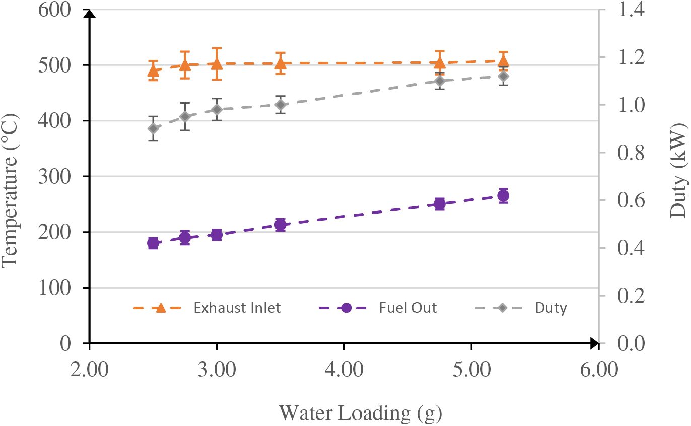
Figure 7: Fuel temperature and duty profiles under different water charges
As shown in Fig. 7, increasing water charge in the thermosyphon, while maintaining the outer wall temperature at the exhaust inlet nearly constant, results in a consistent upward trend in both fuel temperature and thermal duty. This suggests that a higher water charge facilitates increased vaporization and condensation, leading to elevated heat transfer rates from the exhaust to the thermosyphon and subsequently to the fuel. To prevent “dry-out” occurrences and maintain the fuel temperature below 200°C, a water charge of 3.0 grams can be chosen.
3.5 Effect of Fuel Loading Rate
In the investigation, the study focuses on recovering exhaust heat to preheat the fuel prior to its entry into the combustion engine. To optimize the utilization of exhaust heat recovery for fuel warming and improve fuel efficiency, a comprehensive analysis of the influence of fuel loading rates on thermosyphon performance is necessary.
Fig. 8 illustrates the outer wall temperatures corresponding to different fuel loading rates. In the experiments designed to assess the impact of fuel loading, the thermosyphon was filled with 3.0 g of water and 0.0564 g of Argon to attain a peak fuel temperature of 200°C. The exhaust flow rate was fixed at 7.8 g/s, with an inflow temperature of 350°C. The fuel loading was initiated at 20°C.
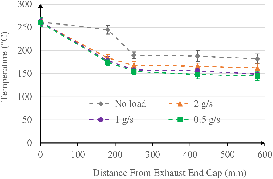
Figure 8: Temperature profile under different fuel loading rates
The results shown in Fig. 8 show a notable decrease in outer wall temperatures when fuel is loaded, attributed to the higher specific heat of the fuel compared to air. Consequently, the thermosyphon can efficiently transfer more heat to the fuel, resulting in lower outer wall temperatures. As the fuel loading rate increases, the changes in outer wall temperature diminish, primarily due to a reduction in the preheating time between the thermosyphon and the fuel. This reduced contact time leads to a decrease in heat dissipation from the thermosyphon to the fuel.
Fig. 9 displays the fuel temperatures at the inlet and outlet, along with the fuel vapor/liquid ratio at various fuel loading rates. The results indicate that an increase in the fuel loading rate leads to a decrease in both the fuel temperatures at the inlet and outlet. This is attributed to the reduced contact time between the thermosyphon and the fuel. Additionally, as the fuel loading rate rises and the heating time decreases, the temperature difference between the fuel inlet and outlet diminishes.
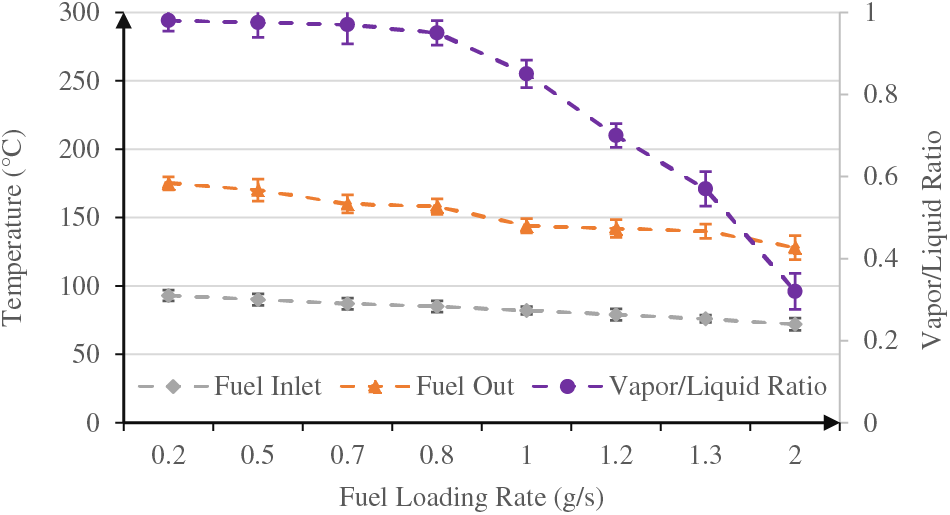
Figure 9: Temperature profiles and vapor/liquid profile under different fuel loading rates
For fuel loading rates below 0.7 g/s, the fuel vapor/liquid ratio consistently remains high with the increasing fuel loading rate. This suggests that a significant portion of the fuel vaporizes within an adequate heating time. However, at high fuel loading rates, the fuel vapor/liquid ratio rapidly decreases due to insufficient heating time to vaporize the fuel.
Considering these findings, an optimal fuel loading rate falls within the range of 0.2 to 0.7 g/s.
Fig. 10 illustrates the heat duty of the thermosyphon, the heat duty of the fuel, and the heat loss in the system at varying fuel loading rates. By using Eq. (2), the heat duty of the thermosyphon can be calculated based on the temperature difference between the inlet and outlet of the exhaust box, as well as the exhaust flow rate. Similarly, the heat duty of the fuel can be calculated according to the temperature difference between the feed-in and feed-out positions of the fuel loading tube attached on the thermosyphon and the fuel loading rate. Heat loss in the system shown in Fig. 10 is defined as the difference between the heat duty of the thermosyphon and the heat duty of the fuel. The findings reveal that, as the fuel loading rate increases up to 0.7 g/s, both thermal duties experience an increase. This suggests that a higher fuel loading rate results in a greater quantity of liquid available for heat transfer. Consequently, higher heat transfer rates are achieved from the exhaust to the thermosyphon and from the thermosyphon to the fuel.
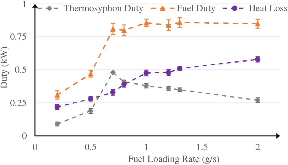
Figure 10: Thermal duty profiles under different fuel loading rates
However, when the fuel loading rate surpasses 0.7 g/s, the thermal duty of the fuel decreases, while the thermal duty of the thermosyphon remains relatively constant. This phenomenon occurs because the heat transfer rate from the thermosyphon to the fuel significantly decreases due to reduced fuel vaporization caused by shorter heating times at higher fuel loading rates.
An experimental investigation was carried out to analyze the thermal performance of a thermosyphon that recovers waste heat from automobile exhaust using a limited fluid charge in this study. The effects of various design parameters on the thermal performance of the thermosyphon were investigated.
The results demonstrate that as the inclination angle increases, a larger volume of water moves toward the condenser, leading to a decrease in condenser temperature and an amplification of the thermosyphon’s temperature gradient. Additionally, increasing the presence of non-condensable gas (NCG) appears to mitigate temperature gradients, potentially compromising the thermosyphon’s performance.
Effective insulation applied to the adiabatic section and exhaust box proves successful in enhancing temperature gradients and, consequently, improving the thermosyphon’s performance. Increasing the water charge within the thermosyphon results in escalated heat transfer rates from the exhaust to the thermosyphon and from the thermosyphon to the fuel.
To prevent “dry-out” phenomena and maintain the fuel temperature below 200°C, a recommended configuration includes a water charge of 3.0 g and an Argon charge of 0.0564 g.
The findings also highlight that fuel loading facilitates enhanced heat dissipation from the thermosyphon. However, with an increase in the fuel loading rate, the heat dissipation from the thermosyphon to the fuel decreases. Below a fuel loading rate of 0.7 g/s, the fuel vapor/liquid ratio remains high, exhibiting an increase with the fuel loading rate. Conversely, at high fuel loading rates, there is a rapid decline in the fuel vapor/liquid ratio as the fuel loading rate increases. In summary, the optimal fuel loading rate for the thermosyphon falls within the range of 0.2 to 0.7 g/s.
Acknowledgement: The author would like to express his sincere gratitude to Dr. James Wilde at Texas State University for his support in this study.
Funding Statement: The author received no specific funding for this study.
Author Contributions: Dr. Bin Xiao served as the sole author of this research paper. His contributions to this study include the conception and design, experimental setups, data collection and analysis, interpretation of results, and the writing and revision of the manuscript. The entire process, from the initial idea to the final submission, was carried out under sole authorship. The author is solely responsible for the intellectual content of this paper and its conclusions.
Availability of Data and Materials: The data that supports the findings of this study are available from the author upon reasonable request.
Conflicts of Interest: The author declares that they have no conflicts of interest to report regarding the present study.
References
1. Mantelli, M. B. H. (2021). Thermosyphons and heat pipes: Theory and applications. New York: Springer. [Google Scholar]
2. Marcinichen, J. B., Armas, G. S. R. B., Rouaze, G., Thome, J. R., Zhang, L. W. (2021). Air-cooled loop thermosyphon cooling system for high heat load CPUs—Part I: Design and performance simulation. 20th IEEE Intersociety Conference on Thermal and Thermomechanical Phenomena in Electronic Systems (iTherm), pp. 59–64. San Diego, CA, USA. [Google Scholar]
3. Darbari, B., Rashidi, S. (2021). Thermal efficiency of flat plate thermosyphon solar water heater with nanofluids. Journal of the Taiwan Institute of Chemical Engineers, 287, 276–287. [Google Scholar]
4. He, T., Mei, C., Long, J. P. (2017). Thermosyphon-assisted cooling system for refrigeration applications. International Journal of Refrigeration, 74, 165–176. [Google Scholar]
5. Vian, J. G., Astrain, D. (2009). Development of a thermoelectric refrigerator with two-phase thermosyphons and capillary lift. Applied Thermal Engineering, 29, 1935–1940. [Google Scholar]
6. Zhang, P., Shi, W., Li, X., Wang, B., Zhang, G. (2018). A performance evaluation index for two-phase thermosyphon loop used in HVAC systems. Applied Thermal Engineering, 131, 825–836. [Google Scholar]
7. Yang, F., Yuan, X., Lin, G. (2003). Waste heat recovery using heat pipe heat exchanger for heating automobile using exhaust gas. Applied Thermal Engineering, 23, 367–372. [Google Scholar]
8. Johnson, I., Choate, W. T. (2008). Waste heat recovery: Technology and opportunities. Washington DC, USA: U. S. Industry, BCS Inc. [Google Scholar]
9. Jouhara, H., Khordehgah, N., Almahmoud, S., Delpech, B., Chauhan, A. et al. (2018). Waste heat recovery technologies and applications. Thermal Science and Engineering Progress, 6, 268–289. [Google Scholar]
10. Yerne, Y. U., Bhusnoor, S. S. (2019). Theoretical thermal analysis of heat recovery by two phase closed thermosyphon from engine exhaust. Heat and Mass Transfer, 55, 3211–3221. [Google Scholar]
11. Ali, S. M., Sarsam, W. S. (2022). Theoretical and experimental investigation of a heat pipe heat exchanger for energy recovery of exhaust air. Heat Transfer, 51(4), 3600–3619. [Google Scholar]
12. Cao, Q., Luan, W., Wang, T. (2018). Performance enhancement of heat pipes assisted thermoelectric generator for automobile exhaust heat recovery. Applied Thermal Engineering, 130, 1472–1479. [Google Scholar]
13. Wang, L., Li, X. (2021). Numerical simulation of heat transfer characteristics of special-shaped heat pipe. 3rd International Conference on Artificial Intelligence and Advanced Manufacture, pp. 20–24. Manchester, UK. [Google Scholar]
14. Hong, Y., Zhao, L., Huang, Y., Li, Q., Jiang, J. et al. (2023). Turbulent thermal-hydraulic characteristics in a spiral corrugated waste heat recovery heat exchanger with perforated multiple twisted tapes. International Journal of Thermal Sciences, 184, 10825. [Google Scholar]
15. Wang, C., Tang, S., Liu, X., Su, G. H., Tian, W. et al. (2020). Experimental study on heat pipe thermoelectric generator for industrial high temperature waste heat recovery. Applied Thermal Engineering, 175, 115299. [Google Scholar]
16. Karana, D. R., Sahoo, R. R. (2021). Performance assessment of the automotive heat exchanger with twisted tape for thermoelectric based waste heat recovery. Journal of Cleaner Production, 283, 124631. [Google Scholar]
Cite This Article
 Copyright © 2024 The Author(s). Published by Tech Science Press.
This work is licensed under a Creative Commons Attribution 4.0 International License , which permits unrestricted use, distribution, and reproduction in any medium, provided the original work is properly cited.
 Downloads
 Citation Tools