
 Submit a Paper
 Propose a Special lssue
 Open Access
ARTICLE

Design and Optimization of Converging-Diverging Liquid Cooling Channels for Enhanced Thermal Management in Lithium-ion Battery Packs
School of Energy and Power Engineering, University of Shanghai for Science and Technology, Shanghai, 200093, China
* Corresponding Author: Tianjiao Zhang. Email:
(This article belongs to the Special Issue: Fluid Flow, Heat and Mass Transfer within Novel Cooling Structures)
Frontiers in Heat and Mass Transfer 2025, 23(3), 819-832. https://doi.org/10.32604/fhmt.2025.064287
Received 11 February 2025; Accepted 18 March 2025; Issue published 30 June 2025
 View Full Text
 Download PDF
Abstract
Power batteries serve as key components of new energy vehicles and are distinguished by their large capacity, long lifespan, high energy density, and stable operation. The strict temperature demands of power battery packs necessitate the development of highly efficient thermal management systems. In this study, a converging-diverging liquid cooling channel featuring a wave shaped structure was designed and analyzed for 18,650-type lithium-ion batteries. To investigate the design methodology for flow channel structure, a thermal model for the heat generation rate of the 18,650-type battery was developed. A comparative analysis of four geometrical configurations of converging-diverging channels. It identified the flat-bottomed channel achieves a maximum reduction of 20.6% in peak internal temperature compared to the other designs. Subsequently, the effects of the arc depth, cell spacing, and Reynolds number on the heat dissipation of the flat-bottomed flow channel were comprehensively investigated. The results demonstrated that increasing the Reynolds number, maximizing the arc depth of the converging-diverging structure, and reducing cell spacing considerably improved the cooling heat dissipation efficiency. Based on the particle swarm optimization algorithm, the optimal parameter combination of the battery pack was obtained at a discharge rate of 2C, comprising an arc depth of 8.5 mm, cell spacing of 1 mm, and Reynolds number of 700. The study provides valuable guidance and references for the practical design and implementation of thermal management systems in new energy vehicles.Keywords
As environmental pollution worsens and fossil fuel reserves continue to diminish, the advancement of new energy vehicles has emerged as a critical approach to address these challenges [1–3]. Power batterie, as the core components of new energy vehicles, have garnered significant attention due to their high energy density, long lifespan, and safety [4,5]. However, temperature significantly impacts battery performance [6–8]. Studies suggest that lithium batteries operate optimally within a temperature range of 293.15 to 318.15 K, with a maximum temperature variation of 278.15 K to maintain optimal functionality [9–11]. Consequently, battery thermal management systems (BTMS) are vital for the safety and reliability of battery packs [12,13].
In recent years, liquid cooling technology has become a prominent focus in BTMS due to its excellent temperature uniformity and high heat transfer efficiency [14–17]. However, challenges such as system complexity, potential leakage risks, and higher implementation costs compared to air-cooled or phase-change material-based systems remain critical considerations for practical applications. Research on liquid-cooled flow channel structures has gradually increased globally for the lithium batteries [18,19]. Ding et al. [20] investigated rectangular flow channel structures and found that increasing the aspect ratio of the channels effectively reduced peak temperature and temperature variation in battery packs. They also observed that alternating the arrangement of channel inlets further enhanced temperature uniformity. Ye et al. [21] optimized a cold plate liquid-cooled flow channel design by considering factors such as cell spacing, cross-sectional area, and the number of cooling channels. Deng et al. [22] examined the effects of the number and arrangement of U-shaped cooling channels, as well as the inlet temperature of cooling water, on BTMS performance, identifying the five channel design as the most effective for heat dissipation.
Several studies have focused on optimizing the geometry of cooling channels. For instance, Jarrett et al. [23] conducted numerical simulations of a serpentine channel cold plate to optimize the flow path, channel width, and length. Xu et al. [24] conducted numerical simulations of a serpentine channel cold plate to optimize the flow path, channel width, and length. Huo et al. [25] designed a liquid-cooled BTMS with micro-channel cold plates, investigating the influence of channel number, cooling water flow direction, and ambient temperature on thermal performance. Lan et al. [26] further explored how varying the number of micro-channels affected thermal performance under different discharge rates, finding that more channels reduced battery temperature. Additionally, Rao et al. [27] developed a wedge-shaped micro-channel BTMS and analyzed the impact of outlet aspect ratio and branching structures on cooling efficiency. Other studies have explored innovations such as spray cooling [28], biomimetic structures [29], and secondary channel enhancements [30], achieving varying levels of success in improving cooling efficiency and temperature uniformity.
Based on the above research progress, it is evident that while significant advancements have been made in the field of battery thermal management systems (BTMS), several limitations remain. While significant advancements have been made in BTMS, critical limitations persist. For instance, conventional U-shaped channels exhibit spatial temperature differences exceeding 8°C, while serpentine designs suffer from 12%–15% higher thermal fluctuations during dynamic cycling. Current air-cooled systems achieve only 60%–70% inter-cell space utilization, leaving substantial thermal management potential untapped. Furthermore, biomimetic structures improve cooling by ~18% but incur 25%–30% higher pressure drops. Therefore, the existing designs may not sufficiently address the need for enhanced heat transfer efficiency through innovative structural configurations, which underscore the urgent need for structurally optimized solutions.
To address these gaps, the present research proposes a novel converging-diverging cooling channel structure based on serpentine and U-shaped structures for 18,650 cylindrical batteries. Four distinct geometries of converging-diverging cooling channels are designed to explore the effects of structural variation on fluid perturbations and heat transfer performance. Numerical simulations are conducted to evaluate the cooling performance of the proposed channel structures. The study aims to provide valuable references and foundations for future research in battery thermal management.
The structure of the converging-diverging cooling flow channel structure is proposed in this study, which was shown in Fig. 1. After being directed into the flow channel through the inlet, the coolant is split into two streams flowing on either side of the battery. A wrap-around structure is implemented at both sides of the flow channel, ensuring that the battery edges are fully in contact with the coolant. The model features a lithium battery pack arranged in a 5 × 5 grid, consisting of 25 cylindrical lithium batteries. A single cell is 18 mm in diameter and 65 mm in height. The battery spacing was 2 mm. The flow channels at the cell inlet and outlet have dimensions of 2 mm × 65 mm rectangular sections. The overall dimensions of the battery pack are 116 mm × 110 mm × 65 mm.
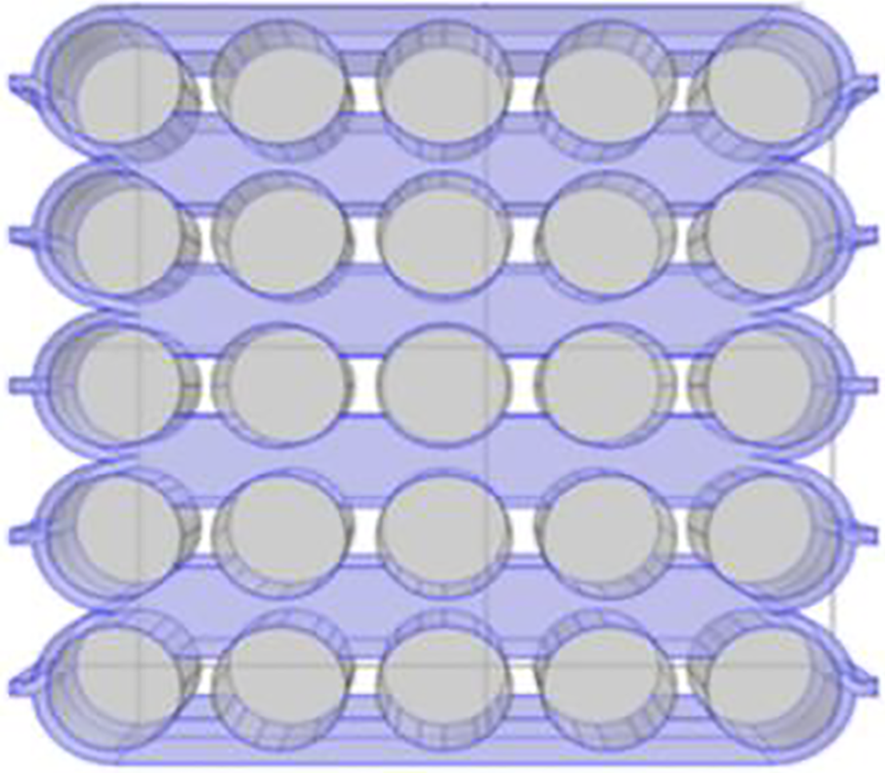
Figure 1: The converging-diverging cooling structures
The heat generation model developed by Bernadi et al. [31] is commonly used to calculate the rate of heat production in batteries. This model, based on energy conservation and assuming uniform distribution of the battery heat source, is as follows:
In the heat production rate model used in this study, the polarisation internal resistance and ohmic internal resistance of the cylindrical lithium-ion batteries are measured using an experimental analytical method [32]. An equation for battery heat production rate is derived based on Bernadi’s heat production formula:
To simplify the process of thermal modelling, this study proposes the following assumptions regarding the lithium battery under investigation: (1) the materials in the lithium battery are isotropic in the circum-axial direction; (2) heat generation within the battery is uniformly distributed; (3) parameters such as ρ, cp, and λ of the battery material are treated as constants, remaining unchanged with temperature variations; (4) radiative heat transfer is neglected. The governing equations for the fluid within the channel with these assumptions are as follows:
Continuity equation:
Momentum equation:
Energy equation:
The finite volume method (FVM) was employed for spatial discretization, with second-order upwind schemes for momentum and energy equations. Pressure-velocity coupling was resolved using the SIMPLE algorithm. Convergence criteria for residuals were set to 10−6 for energy and 10−5 for continuity and momentum.
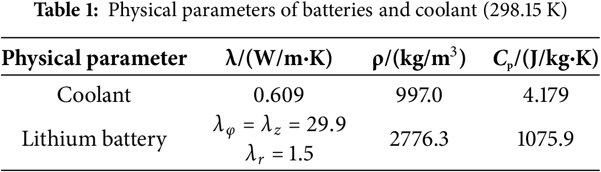
In the simulation, the ambient temperatures are set to 298.15, 303.15, 308.15, and 313.15 K, and the coolant temperatures are set to 293.15, 298.15, 303.15 and 308.15 K. The inlet of the coolant flow channel is defined as a velocity inlet, while the outlet is set as a constant pressure outlet with a relative pressure of 0 MPa. It is assumed that there was no slippage on the walls. Water is chosen as the coolant. Physical parameters of batteries and coolant are shown in Table 1. The convection heat transfer coefficient between the battery module and the surrounding environment was set to 9 W/(m2·K).
The computational domain was discretized using tetrahedral meshes, with localized refinement applied to the near battery surfaces and channel walls. To ensure the accuracy of the simulation results, a mesh independence verification was conducted for the battery pack. The verification was carried out under the following conditions: an environmental temperature of 298.15 K, an inlet coolant temperature of 293.5 K, and a Reynolds number of 50, corresponding to an inlet flow velocity of 0.013 m/s. The highest temperature distributions for different mesh configurations are presented in Fig. 2a. To optimize computational efficiency, a refined mesh with approximately 570,000 elements was employed. The overall mesh configuration of the model is illustrated in Fig. 2b.
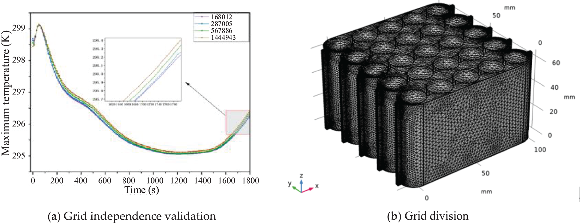
Figure 2: Grid division and independence validation. (a) Grid independence validation (b) Grid division
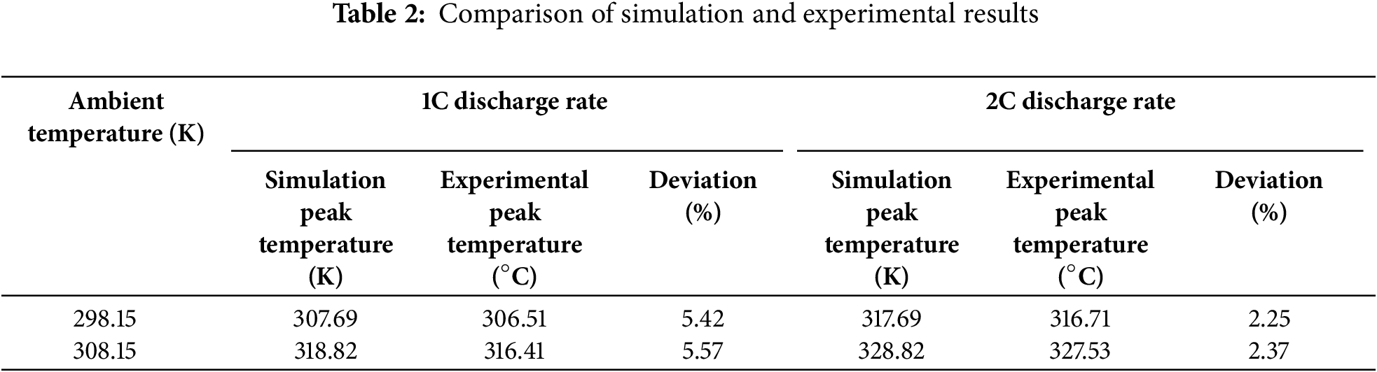
The battery temperature is verified with data from the literature under different ambient temperatures and discharge rates. As shown in Table 2, the peak internal temperature from our simulations closely aligns with the experimental results under two typical test conditions: ambient temperature of 298.15 K and 308.15 K. The results for the peak internal temperature exhibited deviations of less than 6% from the experimental data in the literature [32], as shown in Table 2, verifying the model.
3 Equations and Mathematical Expressions
In this section, the converging-diverging cooling flow channel structures were investigated. The simulation calculations were performed to determine the optimum form of the flow channel structure using altered geometrical shapes, namely semi-circular, right-angled, arcuate, and flat-bottomed for the converging-diverging structures. The four types of converging-diverging flow channels were presented in Fig. 3.
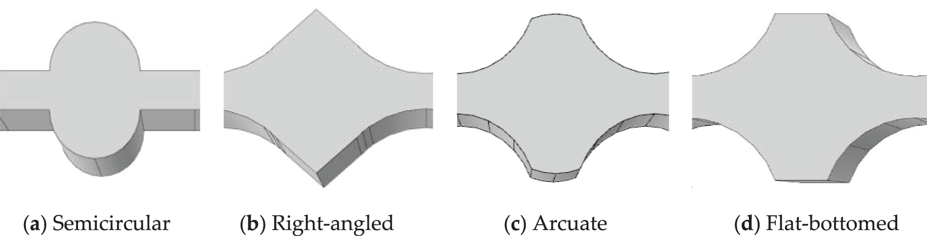
Figure 3: Four different structures of converging-diverging cooling channels. (a) Semicircular (b) Right-angled (c) Arcuate (d) Flat-bottomed
Discharge rate means the battery can be completely discharged in one hour. For instance, if a battery has a capacity of 100 Ah, 1C discharge rate corresponds to a discharge current of 100 A, which will deplete the battery in one hour. In this section, the battery pack’s discharge rate was set to 2C. The surrounding temperature was maintained at 298.15 K, the coolant inlet temperature at 293.15 K, and the Reynolds number at 500. In the structure, the maximum arc depth was 6 mm, and the cell spacing was 4 mm. Fig. 4 showed the temperature contours of the battery pack with various structural forms.
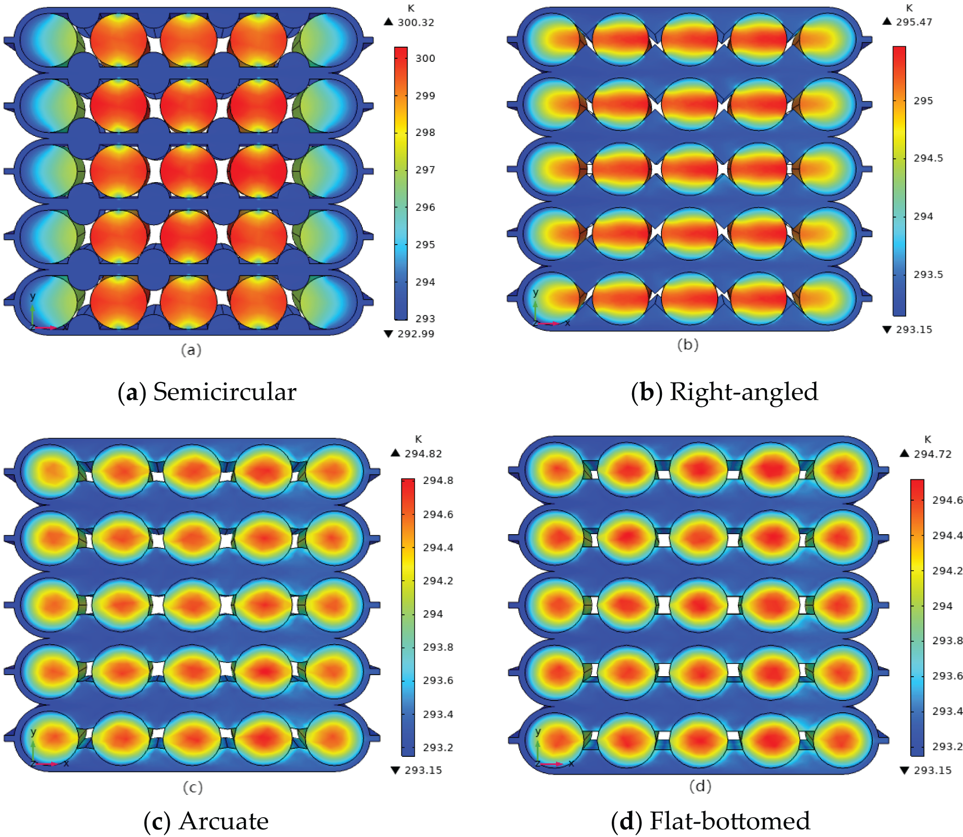
Figure 4: Temperature distribution of battery packs with different converging-diverging cooling channels. (a) Semicircular; (b) Right-angled; (c) Arcuate; (d) Flat-bottomed
As shown in Fig. 4a, the lack of contact between the semi-circular scaling channel and the battery leads to an inability to achieve effective heat transfer. The peak internal temperature reached 300.32 K. Fig. 4b showed that the peak temperature of the right-angled scaling channel is 295.47 K. The heat dissipation uniformity is much stronger than that of the semicircle. Fig. 4c showed that most of the heat collected in the centre of the battery with a peak temperature of 294.82 K. Fig. 4d showed that the highest temperature of the flat-bottom zoom channel is 294.72 K, slightly lower than that of the arcuate zoom channel, indicating the best heat dissipation characteristics.
As shown in Fig. 5, their pressure distribution is similar, and the maximum pressure value is not much different. The maximum pressure drop loss of the semicircular channel is 52.3 Pa, while the minimum pressure drop loss of the right-angled channel is 47.8 Pa, and the pressure drop loss of the arcuate channel, and the flat-bottomed channel is about 49.5 Pa. Due to the converging-diverging cooling flow channel structures, the velocity in the flow channel presents an irregular distribution, which can disturb the fluid, destroy the boundary layer and increase the heat transfer efficiency.
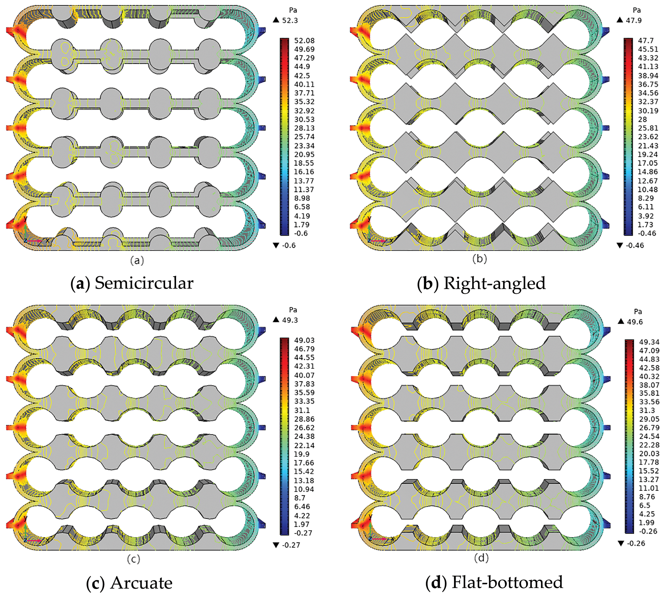
Figure 5: Pressure distribution of battery packs with different converging-diverging cooling channels. (a) Semicircular; (b) Right-angled; (c) Arcuate; (d) Flat-bottomed
Channel structures, models with arc depths (δ) of 0.5~8.5 mm were selected for analysis. For a surrounding temperature of 303.15 K, coolant inlet temperature of 293.15 K, cell spacing of 4 mm, and Reynolds number of 600, and the discharge rates of 1C and 2C was simulated.
Fig. 6 demonstrated that the peak temperature exhibits a more significant reduction with a gradual increase in the arc depth, although the magnitude of this reduction diminished over time. For example, when the arc depth was increased from 0.5 to 2.5 mm, the peak temperature decreases by 1.22 K. However, further increasing the arc depth from 6.5 to 8.5 mm resulted in only a 0.02 K reduction in peak temperature. This suggested that the effect of arc depth on the peak temperature diminishes as the depth increases. The main reason is that with the increase of the maximum arc depth, the heat transfer area between the battery pack and the cooling channel gradually increases, but with the increase of the maximum arc depth, the maximum temperature of the battery pack gradually moves closer to the interior of the single cell, and then blindly increasing the maximum arc depth, the effect gradually weakens. Secondly, the increase of the maximum arc depth changes the cross-sectional area of the YZ axis, which affects the distribution of pressure drop and flow rate, destroys the boundary layer, and enhances the heat transfer effect. Additionally, at a discharge rate of 1C, the peak temperature dropped by 1.54 K when the arc depth increased from 0.5 to 8.5 mm, while at a discharge rate of 2C, the reduction in peak temperature was 2.32 K. When the battery began to discharge, the maximum temperature reached a peak, with the peak value increasing as the arc depth increased.
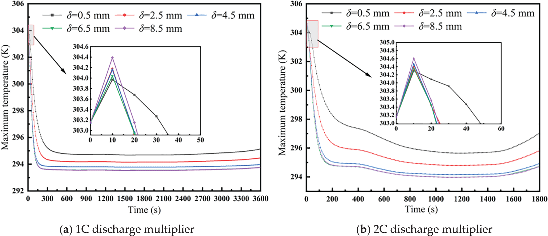
Figure 6: Maximum temperature variations of battery packs at different maximum arc depths. (a) 1C discharge multiplier; (b) 2C discharge multiplier
3.3 Effect of the Cell Spacing
The cell spacing (S) was selected as 2~10 mm. The simulations were performed for the performance of battery packs under 1C and 2C discharge multiplicities at a surrounding temperature of 303.15 K, a coolant inlet temperature of 293.15 K, an arc depth of 5 mm, and a Reynolds number of 600.
Fig. 7 revealed that when the battery pack initially starts discharging, the greater the cell spacing, the lower the peak temperature. As the cell spacing increases, the peak temperature rises; however, the rate of increase gradually diminishes. When the battery spacing increases from 2 to 10 mm, the peak temperature increases by 0.24 K under 1C discharge rate. Under 2C discharge rate, the peak temperature increases by 0.35 K. When the cell spacing is 8 and 10 mm, the peak temperature increases slightly. The main reason is that the cell spacing directly affects the cross-sectional area of the flow channel. A small cell spacing increases the flow velocity within the flow channel, and vice versa. As cell spacing increases, the effect of the decrease in flow velocity caused by the increase in the cross-sectional area gradually weakens. The changes in pressure and flow velocity are not obvious, the fluid disturbance weakens, the boundary layer effect intensifies, and the heat transfer effect is not satisfactory. Overall, cell spacing has minimal impact on the battery’s heat dissipation performance under the simulated operating conditions.
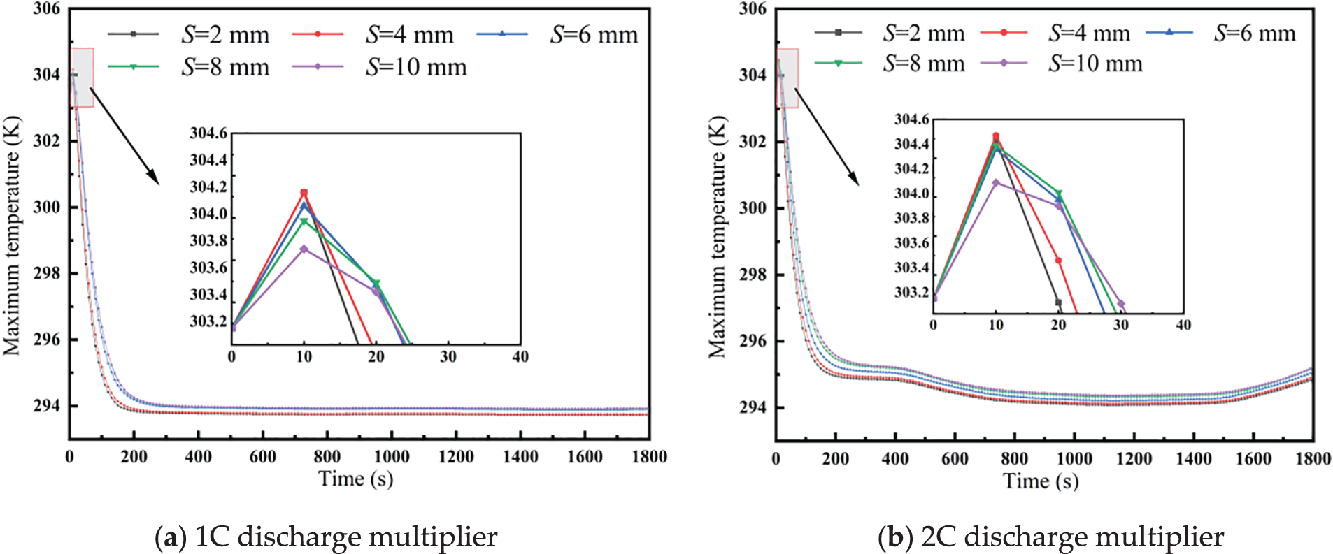
Figure 7: Maximum temperature curves of battery packs at different cell spacing. (a) 1C discharge multiplier; (b) 2C discharge multiplier
3.4 Effect of the Reynolds Number
In this section, the simulation was performed at a surrounding temperature of 298.15 K, coolant inlet temperature of 293.15 K, cell spacing of 4 mm, arc depth of 5 mm, and a Reynolds number range of 100~700. Under these conditions, simulation calculations were performed for the heat dissipation performance of battery packs with discharge rate of 1C and 2C.
Fig. 8 illustrates that, at discharge rates of 1C and 2C, as the Reynolds number increases, the coolant flow rate rises, leading to improved heat dissipation from the battery pack. Consequently, maximum temperature gradually decreases, although the rate of decrease slows down. At a 2C discharge rate, the maximum temperature at a Reynolds number of 100 is significantly different from that of other Reynolds numbers because the battery pack generates more heat. If the flow rate is too low, heat will not be dissipated efficiently or quickly, thereby increasing the battery temperature. This analysis demonstrates that increasing the Reynolds number within a certain range helps reduce the maximum temperature. However, if the Reynolds number becomes too high, it may lead to unnecessary energy losses.
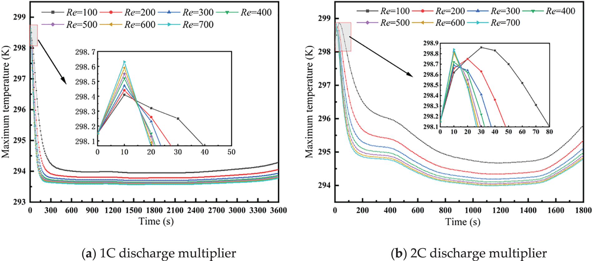
Figure 8: Maximum battery pack temperature curves at different Reynolds numbers. (a) 1C discharge multiplier; (b) 2C discharge multiplier
In order to achieve the optimal design of this flow channel, the LASSO regression equation was adopted by considering the size of the cell spacing, maximum arc depth of the cooling flow channel, and the size of the Reynolds number as independent variables, and with maximum temperature (Z) as dependent variables. By selecting specific independent variables, LASSO regression sample data were derived from COMSOL simulations under conditions of a surrounding temperature of 303.15 K and a coolant inlet temperature of 293.15 K. Using LASSO regression, the functional relationship among the Reynolds number, arc depth, cell spacing, peak temperature, and maximum temperature difference was obtained using LASSO regression. The optimal solution was predicted using the particle swarm algorithm in SPSSPRO after setting the constraints and value ranges. The particle swarm optimization algorithm is a stochastic search algorithm that simulates the foraging behavior of bird flocks. Each solution to a problem is regarded as a “particle” in the search space. The fitness value of a particle is determined by the optimization function, and the particle can control its direction and velocity. These particles search for the optimal solution within the search space. Through information sharing, particles will adjust their search directions, approaching and searching for the solution space where the current optimal particle is located. To achieve the optimal design of this flow channel:
Fig. 9 illustrates the convergence behavior of the particle swarm algorithm. The figure shows the objective function value (the maximum temperature) decreasing monotonically and stabilizing after 300 iterations, confirming the algorithm’s successful convergence.
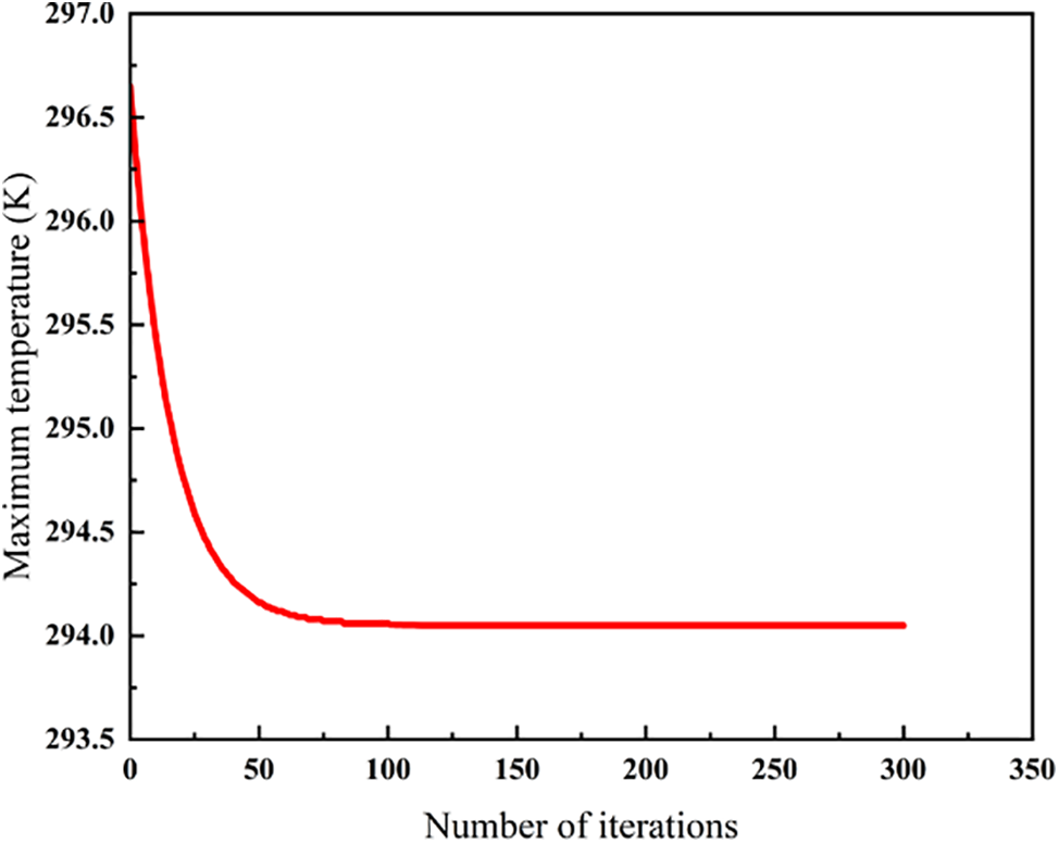
Figure 9: Convergence history of the optimization process
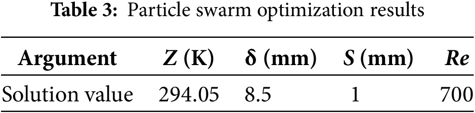
By optimizing the particle swarm algorithm with specific objective functions and constraints, the resulting optimization outcomes are presented in Table 3.
The heat dissipation performance of converging-diverging cooling channel structures for lithium-ion batteries was investigated using numerical simulations. It mainly focuses on the effects of the structural characteristics on the heat dissipation efficiency, including the maximum arc depth, battery spacing, and Reynolds number. The main findings are:
(1) Among the four converging-diverging cooling channel structures investigated, the flat-bottomed channel exhibited superior heat dissipation performance with a maximum reduction of 20.6% in peak internal temperature.
(2) For the flat-bottomed flow channel, increasing the maximum arc depth, reducing battery spacing, and increasing the Reynolds number contributed to enhanced heat dissipation performance.
(3) Using particle swarm optimization methods, it was determined that the optimal heat dissipation performance of the battery was achieved at a maximum arc depth of 8.5 mm, battery spacing of 1 mm, and Reynolds number of 700 at a discharge rate of 2C.
(4) The study focuses on numerical simulations under steady-state conditions, and experimental validation under dynamic operating conditions is needed. Moreover, multi-objective optimization integrating thermal efficiency, pressure drop, and manufacturing costs will be explored in the future.
Acknowledgement: This work was supported by the National Nature Science Foundation of China.
Funding Statement: This research was funded by the National Nature Science Foundation of China, grant number 52406024.
Author Contributions: The authors confirm contribution to the paper as follows: study conception and design: Tianjiao Zhang, Kequn Li and Hua Zhang; data collection: Yibo Xu and Long Li; analysis and interpretation of results: Tianjiao Zhang, Yibo Xu and Long Li; draft manuscript preparation: Tianjiao Zhang and Yibo Xu. All authors reviewed the results and approved the final version of the manuscript.
Availability of Data and Materials: The data that support the findings of this study are available from the corresponding author upon reasonable request.
Ethics Approval: Not applicable.
Conflicts of Interest: The authors declare no conflicts of interest to report regarding the present study.
Abbreviations
| Cp | Specific heat capacity, J/(kg·K) |
| E | Battery voltage, |
| Eoc | Open circuit voltage, V |
| I | Charge and discharge current, |
| M | Maximum temperature difference, |
| p | Pressure, |
| q | Heat flux, W/m2 |
| Re | Reynolds number |
| Rj | Ohmic internal resistance, |
| Rp | Polarization internal resistance, |
| S | Cell spacing, |
| SOC | Battery charge state |
| T | Temperature, |
| t | Discharge time, |
| V | Heat generating volume, |
| Z | Maximum temperature, |
| C | Discharge ratio |
| ρ | Density, kg/m3 |
| μ | Dynamic viscosity, |
| δ | Arc depth, |
| λ | Thermal conductivity, W/(m·K) |
| r | Radial direction |
| φ | Circumferential |
| z | Axial direction |
References
1. Tian J, Wang P, Zhu D. Overview of Chinese new energy vehicle industry and policy development. Green Energy Resour. 2024;2(2):100075. doi:10.1016/j.gerr.2024.100075. [Google Scholar] [CrossRef]
2. Zhang J, Islam MS, Jambulingam M, Lim WM, Kumar S. Leveraging environmental corporate social responsibility to promote green purchases: the case of new energy vehicles in the era of sustainable development. J Clean Prod. 2024;434(1):139988. doi:10.1016/j.jclepro.2023.139988. [Google Scholar] [CrossRef]
3. Gu X, Wang M, Wu J. An empirical study on the green effects of new energy vehicle promotion in the context of global carbon neutrality. Chin J Popul, Resour Environ. 2022;20:332–40. doi:10.1016/j.cjpre.2022.11.004. [Google Scholar] [CrossRef]
4. Liu H, Shi H, Shen H, Xie G. The performance management of a Li-ion battery by using tree-like mini-channel heat sinks: experimental and numerical optimization. Energy. 2019;189:116150. doi:10.1016/j.energy.2019.116150. [Google Scholar] [CrossRef]
5. Niu H, Zhang N, Lu Y, Zhang Z, Li M, Liu J, et al. Strategies toward the development of high-energy-density lithium batteries. J Energy Storage. 2024;88:111666. doi:10.1016/j.est.2024.111666. [Google Scholar] [CrossRef]
6. Karthik A, Kalita P, Garg A, Gao L, Peng X, Chen S. A Novel MOGA approach for power saving strategy and optimization of maximum temperature and maximum pressure for liquid cooling type battery thermal management system. Int J Green Energy. 2020;18(1):80–9. doi:10.1080/15435075.2020.1831507. [Google Scholar] [CrossRef]
7. Arora S. Selection of thermal management system for modular battery packs of electric vehicles: a review of existing and emerging technologies. J Power Sour. 2018;400:621–40. doi:10.1016/j.jpowsour.2018.08.020. [Google Scholar] [CrossRef]
8. Feng XH, Lou YL, Zhang K, Li ZZ, Zhang ML. Optimization of liquid-cooled lithium-ion battery thermal management system under extreme temperature. J Energy Storage. 2024;99(15):113214. doi:10.1016/j.est.2024.113214. [Google Scholar] [CrossRef]
9. Qian X, Xuan D, Zhao X, Shi Z. Heat dissipation optimization of lithium-ion battery pack based on neural networks. Appl Therm Eng. 2019;162(4):114289. doi:10.1016/j.applthermaleng.2019.114289. [Google Scholar] [CrossRef]
10. Liang J, Gan Y, Li Y, Tan M, Wang J. Thermal and electrochemical performance of a serially connected battery module using a heat pipe-based thermal management system under different coolant temperatures. Energy. 2019;189:116233. doi:10.1016/j.energy.2019.116233. [Google Scholar] [CrossRef]
11. Xiao H, J E, Tian S, Huang Y, Song X. Effect of composite cooling strategy including phase change material and liquid cooling on the thermal safety performance of a lithium-ion battery pack under thermal runaway propagation. Energy. 2024;295:131093. doi:10.1016/j.energy.2024.131093. [Google Scholar] [CrossRef]
12. Xin S, Wang C, Xi H. Thermal management scheme and optimization of cylindrical lithium-ion battery pack based on air cooling and liquid cooling. Appl Therm Eng. 2023;224:120100. doi:10.1016/j.applthermaleng.2023.120100. [Google Scholar] [CrossRef]
13. Zhang C, Yan R, Li H, Tang Q, Zhao Q. Experimental and numerical study on flow and heat transfer characteristics in rectangular channels with leaf-shaped pin fins. Front Heat Mass Transfer. 2025;1–10. doi:10.32604/fhmt.2025.061469. [Google Scholar] [CrossRef]
14. Deng Y, Feng C, J E, Zhu H, Chen J, Wen M, et al. Effects of different coolants and cooling strategies on the cooling performance of the power lithium-ion battery system: a review. Appl Therm Eng. 2018;142:10–29. doi:10.1016/j.applthermaleng.2018.06.043. [Google Scholar] [CrossRef]
15. Mohammed KA, Saleem AM, Obaid ZAH. Numerical investigation of Nusselt number for nanofluids flow in an inclined cylinder. Front Heat Mass Transfer. 2021;16:1–8. doi:10.5098/hmt.16.20. [Google Scholar] [CrossRef]
16. Akbarzadeh M, Kalogiannis T, Jaguemont J, Jin L, Behi H, Karimi D, et al. A comparative study between air cooling and liquid cooling thermal management systems for a high-energy lithium-ion battery module. Appl Therm Eng. 2021;198(2):117503. doi:10.1016/j.applthermaleng.2021.117503. [Google Scholar] [CrossRef]
17. Zhao C An, Jia Z, Lei Z. Structure optimization of liquid-cooled plate for electric vehicle lithium-ion power batteries. Int J Therm Sci. 2024;195:108614. doi:10.1016/j.ijthermalsci.2023.108614. [Google Scholar] [CrossRef]
18. Wu C, Sun Y, Tang H, Zhang S, Yuan W, Zhu L, et al. A review on the liquid cooling thermal management system of lithium-ion batteries. Appl Energy. 2024;375(45):124173. doi:10.1016/j.apenergy.2024.124173. [Google Scholar] [CrossRef]
19. Nie J, Liu Z, Su J, Zhang C, Li Y. Multi-objective optimization of liquid cooling system for lithium-ion battery. J Energy Storage. 2024;103(15):114380. doi:10.1016/j.est.2024.114380. [Google Scholar] [CrossRef]
20. Ding Y, Wei M, Liu R. Channel parameters for the temperature distribution of a battery thermal management system with liquid cooling. Appl Therm Eng. 2021;186(2):116494. doi:10.1016/j.applthermaleng.2020.116494. [Google Scholar] [CrossRef]
21. Ye B, Rubel MRH, Li H. Design and optimization of cooling plate for battery module of an electric vehicle. Appl Sci. 2019;9(4):754. doi:10.3390/app9040754. [Google Scholar] [CrossRef]
22. Deng T, Zhang G, Ran Y. Study on thermal management of rectangular Li-ion battery with serpentine-channel cold plate. Int J Heat Mass Transf. 2018;125:143–52. doi:10.1016/j.ijheatmasstransfer.2018.04.065. [Google Scholar] [CrossRef]
23. Jarrett A, Kim IY. Design optimization of electric vehicle battery cooling plates for thermal performance. J Power Sour. 2011;196:10359–68. doi:10.1016/j.jpowsour.2011.06.090. [Google Scholar] [CrossRef]
24. Xu H, Zhang X, Xiang G, Li H. Optimization of liquid cooling and heat dissipation system of lithium-ion battery packs of automobile. Case Stud Therm Eng. 2021;26:101012. doi:10.1016/j.csite.2021.101012. [Google Scholar] [CrossRef]
25. Huo Y, Rao Z, Liu X, Zhao J. Investigation of power battery thermal management by using mini-channel cold plate. Energy Convers Manag. 2015;89:387–95. doi:10.1016/j.enconman.2014.10.015. [Google Scholar] [CrossRef]
26. Lan C, Xu J, Qiao Y, Ma Y. Thermal management for high power lithium-ion battery by minichannel aluminum tubes. Appl Therm Eng. 2016;101:284–92. doi:10.1016/j.applthermaleng.2016.02.070. [Google Scholar] [CrossRef]
27. Rao Z, Zhang X. Investigation on thermal management performance of wedge-shaped microchannels for rectangular Li-ion batteries. Int J Energy Res. 2019;43(8):3876–90. doi:10.1002/er.4571. [Google Scholar] [CrossRef]
28. Jiang Z, Li H, Sun Z, Qu Z. Experimental study on 18650 lithium-ion battery-pack cooling system composed of heat pipe and reciprocating air flow with water mist. Int J Heat Mass Transf. 2024;222(5):125171. doi:10.1016/j.ijheatmasstransfer.2024.125171. [Google Scholar] [CrossRef]
29. Yao F, Guan X, Yang M, Wen C. Study on liquid cooling heat dissipation of Li-ion battery pack based on bionic cobweb channel. J Energy Storage. 2023;68(2):107588. doi:10.1016/j.est.2023.107588. [Google Scholar] [CrossRef]
30. Fan L, Li J, Chen Y, Zhou D, Jiang Z, Sun J. Study on the cooling performance of a new secondary flow serpentine liquid cooling plate used for lithium battery thermal management. Int J Heat Mass Transf. 2024;218(12):124711. doi:10.1016/j.ijheatmasstransfer.2023.124711. [Google Scholar] [CrossRef]
31. Bernardi D, Pawlikowski E, Newman J. A general energy balance for battery systems. J Electrochem Soc. 1985;132(1):5. doi:10.1149/1.2113792. [Google Scholar] [CrossRef]
32. Smith K, Wang C. Power and thermal characterization of a lithium-ion battery pack for hybrid electric vehicles. J Power Sour. 2006;1(160):662–73. doi:10.1016/j.jpowsour.2006.01.038. [Google Scholar] [CrossRef]
Cite This Article
 Copyright © 2025 The Author(s). Published by Tech Science Press.
This work is licensed under a Creative Commons Attribution 4.0 International License , which permits unrestricted use, distribution, and reproduction in any medium, provided the original work is properly cited.
 Downloads
 Citation Tools