
 Submit a Paper
 Propose a Special lssue
 Open Access
ARTICLE

Experimental Study of a Helium Sorption Cooler with Low Temperature Fluctuation and Long Hold Time below 1 K
1 School of Energy and Power Engineering, University of Shanghai for Science and Technology, 516 Jungong Road, Shanghai, 200093, China
2 Shanghai Institute of Technical Physics, Chinese Academy of Science, 500 Yutian Road, Shanghai, 200083, China
3 University of Chinese Academy of Sciences, Beijing, 100049, China
* Corresponding Authors: Kongkuai Ying. Email: ; Shaoshuai Liu. Email:
Frontiers in Heat and Mass Transfer 2025, 23(3), 739-750. https://doi.org/10.32604/fhmt.2025.064532
Received 18 February 2024; Accepted 23 April 2025; Issue published 30 June 2025
 View Full Text
 Download PDF
Abstract
Helium sorption cooler technology is a key means to realize highly reliable low-vibration very low-temperature environments, which have important applications in fields such as quantum computing and space exploration. The laboratory designed a superfluid suppression small hole and a multi-ribbed condenser, developed a reliable-performance helium sorption cooler (HSC), and conducted experimental studies. Experimental results show that the prototype can achieve the lowest cooling temperature of 873 mK without load by filling 6 MPa helium at room temperature. The low-temperature hold time is 26 h, and the temperature fluctuation is within 0.8 mK. The cooling power of the helium sorption cooler is 1 mW @ 0.98 K @ 3.5 h. Experimental results indicate that when the charging pressure is reduced to 4 MPa, the minimum temperature decreases to 836 mK, and the hold time shortens to 16 h. When the pre-cooling temperature increases from 3.9 to 4.9 K, the hold time is reduced to 3 h.Keywords
In recent years, due to the rapid development of quantum computing, superconductivity technology, deep space exploration [1,2] and other fields, the demand for extremely low temperature environments has been increasing [3]. For example, in quantum computing, to keep the quantum state of a quantum bit stable for a long time, the thermal noise, thermal excitation and mechanical vibration should be minimized, which requires an extremely low temperature environment with high stability and less vibration [4]. Currently, the commonly used refrigeration methods that can reach below 1 K include Dilution Refrigeration (DR) [5], Adiabatic Demagnetization Refrigeration (ADR) [6] and Helium Sorption Cooler (HSC) [7]. Helium Sorption Cooler is a good choice for creating an extremely low temperature environment with high stability and low vibration due to its lack of moving parts [8,9], simple structure and high reliability [10,11]. HSC with 4He as workgas can reach temperatures of 800 mK and are generally used as pre-cooling stages for lower temperatures [12,13].
Due to the different saturation vapor pressures of 3He and 4He, Helium Sorption Cooler reach different minimum temperatures with these two different workpieces. The study of helium sorption coolers with 3He as the work material has been going on since 1985, when Torre et al. first reported a closed single-cycle helium adsorption chiller for the cooling of detectors in operation [14]. In 2004, Devlin et al. used a Helium Sorption Cooler with 4He as the working fluid, capable of reaching a minimum temperature of 700 mK, as a pre-cooling stage, allowing the 3He Helium Sorption Cooler to achieve a minimum temperature of 286 mK [15]. In 2008, Duband et al. developed HSC for the SPIRE and PACS instruments on board the Herschel satellite, using a 2367 L superfluid helium tank as a pre-cooler to bring the minimum temperature below 300 mK [16].
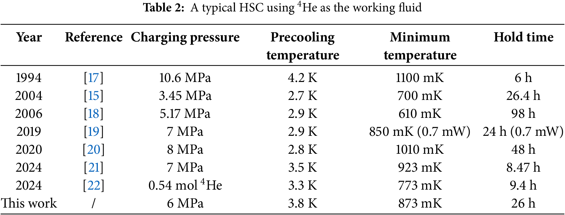
For HSC with 4He as the working fluid, in 1994, Bock et al. used a liquid helium cryostat as the precooling stage, charging helium gas at 10.6 MPa at room temperature. With a precooling temperature of 4.2 K, the system achieved a minimum temperature of 1.1 K with a hold time of 6 h [17]. In 2004, Devlin et al. developed a two-stage HSC using a pulse tube cryocooler as the precooling stage. When operating independently, the first-stage HSC, using 4He as the working fluid, achieved a minimum temperature of 700 mK with a hold time of 26.4 h under a charging pressure of 3.45 MPa and a precooling temperature of 2.7 K [15]. In 2006, Lau et al. proposed a simple model for gas, heat flow, and thin-film behavior in an HSC. They optimized the low-temperature performance by considering the effect of a throttling orifice in suppressing superfluid helium film flow. Under the conditions of a 508 μm orifice, a charging pressure of 5.17 MPa, and a precooling temperature of 2.9 K, the HSC achieved a minimum temperature of 0.61 K with a hold time of 98 h [18]. In 2019, Andrew et al. introduced a simple and efficient membrane-breaking method and developed an HSC based on this technique. With a charging pressure of 7 MPa, a precooling temperature of 2.9 K, and a load of 0.7 mW, the system reached a minimum temperature of 850 mK with a hold time of 24 h [19]. In 2020, Duband et al. developed a sub-Kelvin cooler for the BICEP experiment. The 4He-based HSC reached a minimum temperature of 1.01 K with a hold time of 48 h under a charging pressure of 8 MPa and a precooling temperature of 2.8 K [20]. In 2024, Li et al. measured the isothermal adsorption curves of three types of carbon on 4He and established a cooling capacity prediction model to develop an HSC. Their system achieved a minimum temperature of 923 mK with a hold time of 8.47 h under a charging pressure of 7 MPa and a precooling temperature of 3.5 K [21]. Also in 2024, Lei et al. analyzed the relationship between the working fluid amount and cooling performance based on adsorption refrigeration principles and designed an HSC. With 0.54 mol of helium gas and a precooling temperature of 3.3 K, the HSC reached a minimum temperature of 773 mK with a hold time of 9.4 h [22].
Overall, HSC are attracting a large number of space applications and other applications requiring high stability and vibration-free operation due to their obvious advantages [23]. In this study, we systematically optimized and designed a prototype HSC, which achieved a minimum temperature of 873 mK and a hold time of 26 h, demonstrating excellent performance and serving as a reliable platform for experimental research. Based on this platform, experimental studies and analyses of the HSC were carried out.
2 HSC Structure and Experimental Set-Up
HSC consists of an adsorption pump, condenser, evaporator, and interconnected pump tubes [24]. Its working principle is decompression evaporation refrigeration, which is controlled by using the activated carbon’s strong or weak ability to absorb helium at different temperatures [25]. The workflow of the HSC is shown in Fig. 1 and is divided into the condensation (desorption) process and the evaporation (sorption) process [26]. The condenser is connected to the 4 K-stage cold platform, and the adsorption pump is connected to and switched off from the 4 K-stage cold platform through a heat switch. During the condensation process, the heat switch is switched off, the adsorption pump is heated, and the helium is desorbed from the activated carbon and condensed into liquid helium through the condenser and into the evaporator. During evaporation, the heating of the adsorption pump is stopped, the heat switch is turned on, the pressure in the evaporator is lowered, and the helium vapor evaporates along the saturation curve [27]. During the condensation process, the condenser directly affects the condensation rate, and it is crucial to ensure that the condenser has sufficient heat exchange capacity [28]. In the evaporation process, the temperature will decrease below λ point (2.172 K), and liquid helium will transition into the superfluid state [29]. The presence of superfluid helium significantly reduces the performance and efficiency of HSC, making the limitation of superfluid helium one of the key areas of research in HSC development.
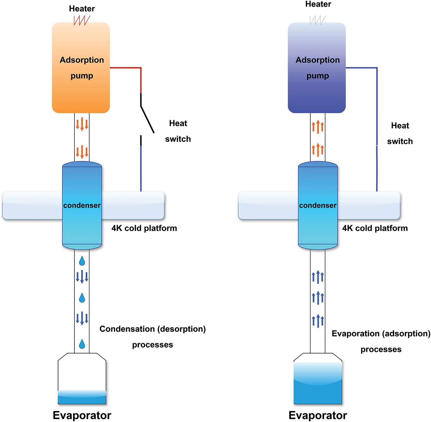
Figure 1: Principle of operation of HSC
2.2 Analysis and Design of Key Components
In HSC, the main task of the condenser is to condense the helium desorbed from the adsorption pump into liquid helium. The design of the condenser determines whether the helium can be condensed quickly [30] and efficiently, contributing to the efficient operation of the subsequent evaporation process [31]. At the same time, the structure of the condenser affects the flow state of the helium. To improve the heat exchange capacity of the condenser, optimize the condensation temperature and the helium flow state, we have optimized the design of a condenser for an HSC, which is shown in the three-dimensional schematic diagram in Fig. 2. The condenser is in the form of a multi-ribbed sheet with a diameter of 10 mm [32], a height of 30 mm and a round inlet tube with a diameter of 6 mm at the top. Inside, there are 36 slit channels, each with a width of 0.02 mm.
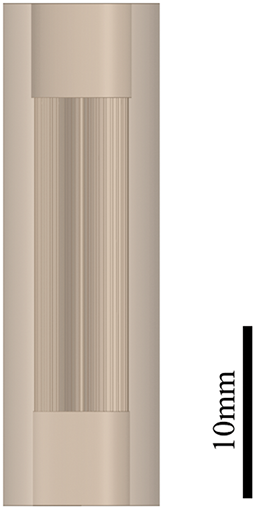
Figure 2: Condenser 3D model
To verify the pre-cooling performance of the condenser, a three-dimensional flow simulation analysis was conducted using the commercial simulation software FLUENT to study the multiphase flow inside the condenser [33]. Given that the VOF (Volume of Fluid) model can effectively track the phase interface, it was selected as the multiphase flow model. The k-ε turbulence model was chosen to enhance thermal effects and curvature correction. The simulated model was validated for grid-independence. Since the condensed liquid helium from the condenser flows into the evaporator, the condensation state and cooling rate of helium were evaluated by observing the temperature changes within the condenser [34]. The comparison between simulation and experimental results is shown in Fig. 3. Both the simulation and experiment show a rapid temperature drop starting from 5.16 K. The cooling rate in the experiment closely matches the simulated results. After 166 s, the simulated temperature stabilizes at 3.35 K, whereas the experimental temperature reaches 3.35 K in 161 s. The simulation results align well with the experimental data, demonstrating that the condenser can efficiently condense helium gas into liquid helium, which then stably accumulates at the bottom of the evaporator.
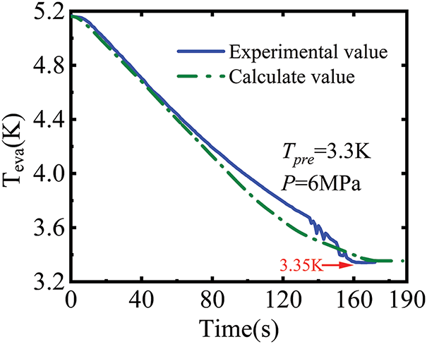
Figure 3: Comparison of condensation process simulation and experimental evaporator temperature variation
Below λ point (2.172 K), liquid helium transitions to a superfluid state, exhibiting non-viscosity, frictionless flow, and high thermal conductivity. This causes it to form a film on contact surfaces and flow upward to transfer heat. During evaporation, superfluid helium rises into the pump tube, where it either evaporates or returns as liquid droplets. The high thermal conductivity may disrupt the heat exchange process, and the return of droplets adds parasitic heat load. Superfluid evaporation increases internal vapor pressure, limiting the HSC’s minimum temperature. Additionally, mass changes in helium within the evaporator affect the hold time. Thus, optimizing the superfluid suppression design is crucial for improving performance.
The design of the superfluid suppression requires the breaking of the superfluid film in order to reduce the effect of the superfluid helium on the HSC. The mass transport rate of the film is calculated as follows:
where
where
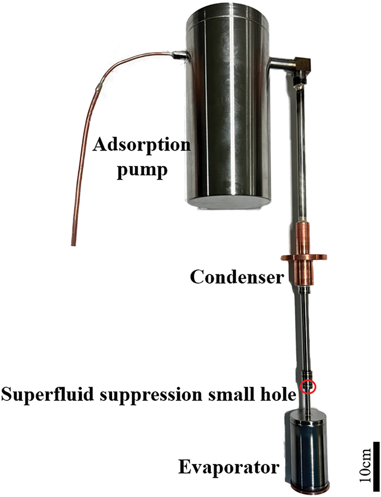
Figure 4: HSC prototype
Based on the working principle of HSC, the experimental system of HSC was built, and the schematic diagram of the experimental system is shown in Fig. 5. The experimental system uses a G-M cooler to provide cooling to the 2-stage cold stage. The flange on the condenser of the HSC used for the experiment facilitates the fixing and thermal linking of the condenser to the 2-stage cold table, and there are screw holes on the lower side of the evaporator for fixing the temperature sensor. The adsorption pump and evaporator are wrapped with multiple layers of insulation to reduce heat radiation from other components to the HSC. The heat switch uses a gas-gap heat switch, which is fixed at the bottom end to the 2-stage cooler table and is thermally connected to the adsorption pump using a flexible copper chain on the opposite side. To minimize the effects of thermal radiation, the system is fitted with copper radiation shielding between the 1-stage and 2-stage cooling tables of the G-M cooler. In addition, key components of the system are insulated with multiple layers of thermal insulation, which significantly reduces radiant heat transfer from the external environment. Ceramic Heaters are installed on the adsorption pumps and on the small adsorption pumps of the gas-gap heat switch, which are controlled by a precision DC heating power supply.
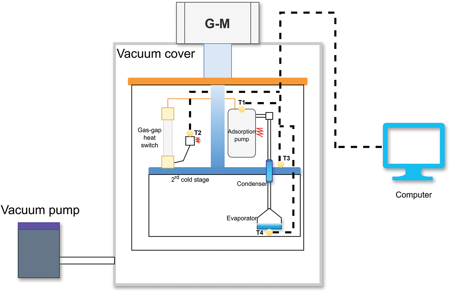
Figure 5: The HSC experimental system
Four calibrated thermometers were installed to measure temperatures. T1 was used to measure the adsorption pump, T2 was used for the small adsorption pump on the gas-gap heat switch, T3 was used for the 2-stage cold table, and T4 was used for the evaporator. The thermometers for T1, T2, and T3 all used Lake Shore’s Cernox thermometers [35], model CX-1050, which have a measuring range of 1.4 to 420 K. Since the evaporator can reach temperatures below 1 K, the T4 on the evaporator uses a Cernox thermometer, model CX-1010, with a measuring range of 0.1~420 K. The thermometers and the heating pads are all screwed in place, and the contact surfaces are coated with heat-conducting adhesive. A Lake Shore Model 224 temperature monitor was used. At the beginning of the experiment, a vacuum pump was used to evacuate the whole system, and when the pressure dropped below 1 Pa, the G-M cooler was switched on and the pre-cooling stage began. After about 40 h, the temperature of the 2-stage cold stage dropped to about 4 K or less, and the temperature of the adsorption pump dropped to about 40 K or less. At this stage it is possible to start controlling the heating power supply to realize the condensation process as well as the evaporation process.
Since the experiment involves temperature measurements, the combined error of the experimental system is calculated from the following:
where
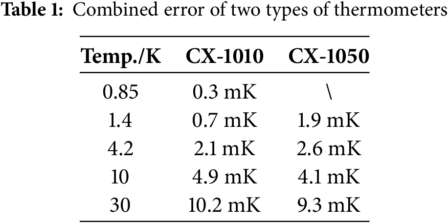
According to the thermometer manufacturer Lake Shore provided by the calibration test information can be obtained from the calibration error of the two types of thermometers, the random error is calculated through the test analysis, Table 1 gives the combined error of the two thermometers at different temperatures.
3 Experimental Results and Discussion
3.1 Prototype Experiment Results
The prototype of the HSC is shown in Fig. 6. As illustrated in Fig. 6a, the temperature of the adsorption pump, T1, initially decreases slowly. This is because the outer shell of the adsorption pump and the connecting pump tube between the adsorption pump and the condenser are made of stainless steel, which has a relatively high thermal resistance, resulting in a slow temperature drop. Moreover, above 32 K, activated carbon begins to desorb helium gas, so the adsorption pump maintains a temperature of around 36 K for nearly 4 h. During this period, the evaporator temperature T4 is nearly the same as the second-stage cold head temperature T3, indicating that helium has already condensed into liquid and accumulated in the evaporator.
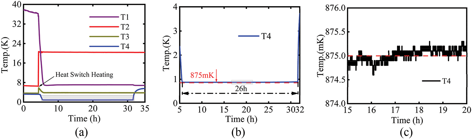
Figure 6: Temperature changes during experiments with the HSC. (a) Temperature change of the whole machine; (b) Temperature change during evaporation; (c) Temperature fluctuation after 9 h of hold
After approximately 4 h, the heating power for the small adsorption pump on the gas-gap heat switch is turned on, causing the temperature T2 to rise. When T2 reaches 21 K, the heat switch transitions to its conducting state. At this point, the temperature of the adsorption pump T1 begins to decrease rapidly, while the second-stage cold head temperature T3 slightly increases. When T1 drops to 24 K, the evaporator enters the evaporation process, and the evaporator temperature T4 begins to decrease rapidly. After about one hour of cooling, T4 reaches its minimum temperature and enters a stable state. At this point, the temperature of the adsorption pump is maintained at 7 K, and the second-stage cold head temperature T3 remains stable at 3.8 K.
Fig. 6b illustrates the temperature profile of the evaporator during the evaporation process. The evaporator reached its lowest temperature of 875 mK at 5.5 h, and the temperature remained below 0.9 K for a duration of 26 h. At 31.5 h, the evaporator temperature rapidly increased as the liquid helium evaporation process was completed. As shown in Fig. 6a, the evaporator temperature sharply rose and reached approximately 5.5 K. The evaporator temperature is higher than the temperature of the second-stage cold head (T3) at 3.8 K because the evaporator temperature rises to match the temperature inside the second-stage radiation shield. Due to factors such as radiative heat leakage, the temperature inside the second-stage shield is slightly higher than that of the cold head (T3). Fig. 6c demonstrates that the temperature fluctuation of the evaporator was minimal, remaining within 1 mK after 9 h of steady operation. The experiment measured the cooling capacity of the helium sorption cooler to be 1 mW @ 0.98 K @ 3.5 h.
3.2 Comparison of Cooling Performance at Different Charging Pressures
The experimental test was continued after charging the HSC with 4 MPa of helium at room temperature and the temperature variation obtained is shown in Fig. 7. At a charging pressure of 4 MPa, the evaporator starts the evaporation process with a rapid cooling down from 4 K. After 1 h, the temperature gradually stabilizes and continues to decrease slowly. 5 h later the temperature reaches a minimum of 837 mK. 13 h later the temperature rises slowly, with a maximum increase above 1 K. The temperature of the evaporator increases to a maximum of 1.1 K. At 22 h, the temperature rises sharply, and the liquid helium evaporation is completed. The hold time of the HSC below 1 K at 4 MPa charging pressure is 16 h, and the time of liquid helium evaporation is 20 h. Comparison with the charging pressure of 6 MPa shows that the charging pressure of the helium at room temperature has a great influence on the minimum temperature, the hold time, and the temperature stability of HSC. As the charging pressure decreases, the pressure at each stage of the system also decreases accordingly. The system pressure during the evaporation phase will also drop. Since the HSC operates based on evaporation under reduced pressure, the saturation temperature of helium decreases with decreasing pressure. Therefore, lowering the charging pressure results in a lower minimum temperature of the HSC. However, a lower charging pressure also reduces the amount of helium charged into the system, which leads to a smaller amount of liquid helium during the evaporation phase and thus significantly shortens the hold time. Moreover, with the decrease in charging pressure, the temperature stability of the HSC becomes poorer.
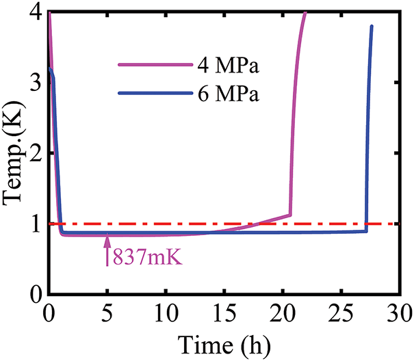
Figure 7: Comparison of temperature changes during evaporation in the evaporator of the HSC at different pressures
3.3 Comparison of Cooling Performance at Different Pre-Cooling Temperatures
Experimental tests were conducted by changing the pre-cooling temperature of the condenser condensation process, and the resulting temperature variations are shown in Fig. 8. During the evaporation stage, due to the constant charging pressure, the system pressures at pre-cooling temperatures of 4.9 and 3.9 K are similar, leading to the same minimum temperature of 837 mK. However, the HSC with a pre-cooling temperature of 4.9 K has a hold time of only 3 h. An increase in the pre-cooling temperature leads to insufficient liquid helium condensation during the condensation process, significantly reducing the mass of liquid helium and greatly shortening the hold time. The cooling rate of the evaporator is more closely related to the temperature of the adsorption pump, and the effect of the pre-cooling temperature is relatively small. Therefore, when the temperature of the adsorption pump is not changed, the cooling rate of the evaporator is the same at different pre-cooling temperatures.

Figure 8: Variation of evaporator temperature of HSC at different pre-cooling temperatures
3.4 The HSC Performance Comparison
Table 2 summarizes this study and several typical HSCs. It can be observed that the charging pressure and precooling temperature have significant effects on the performance of HSCs. Previous studies have mainly focused on overall system performance, superfluid helium suppression, and activated carbon adsorption characteristics. In this study, we developed an HSC with a minimum temperature of 875 mK and a hold time of 26 h. Additionally, we conducted experimental research on different charging pressures and precooling temperatures, analyzing their impact on the performance of the HSC. This study provides valuable guidance for the future development of HSCs.
The helium sorption cooler (HSC), with its advantages of no moving parts, high reliability, and simple structure, has attracted significant attention in the field of ultra-low temperatures. By optimizing the design of the multi-ribbed condenser and improving the small-hole structure for superfluid suppression, our laboratory has designed and developed a prototype HSC and established a complete experimental system for its performance testing. When charged with 6 MPa of helium at room temperature, the prototype achieved a minimum temperature of 875 mK and a hold time of 26 h, with a temperature fluctuation of only 0.8 mK during the hold time. The cooling power of the HSC reached 1 mW @ 0.98 K @ 3.5 h, making it a reliable platform for experimental research.
We conducted experimental studies under different charging pressures and pre-cooling temperatures. The results show that when the charging pressure was reduced from 6 to 4 MPa, the minimum temperature dropped from 875 to 836 mK, but the hold time was shortened to 16 h. When the pre-cooling temperature increased from 3.9 to 4.9 K, the minimum temperature remained unchanged, but the hold time was further reduced to 3 h. These experimental studies provide valuable guidance for the future development and optimization design of HSC systems
Acknowledgement: The authors sincerely thank the editors of FHMT—Frontiers in Heat and Mass Transfer, and also express their gratitude to the reviewers for their constructive suggestions on this article.
Funding Statement: This work is supported by the Hundred Talents Program of the Chinese Academy of Sciences, the Pre-Research Project JZX7Y20220414101801, the Strategic Priority Research Program of Chinese Academy of Sciences (No. XDB35000000), the National Natural Science Foundation Projects (No. 51806231).
Author Contributions: The authors confirm contribution to the paper as follows: study conception and design: Tianshuo Liu, Lihao Lu, Kongkuai Ying; data collection: Tianshuo Liu, Yang Wang, Kangjun Liu; analysis and interpretation of results: Tianshuo Liu, Zilong Wang, Shaoshuai Liu, Xiaoyu Cui; draft manuscript preparation: Tianshuo Liu, Kongkuai Ying; project administration: Zhenhua Jiang, Xiaoyu Cui; funding acquisition: Shaoshuai Liu, Zhenhua Jiang. All authors reviewed the results and approved the final version of the manuscript.
Availability of Data and Materials: The authors confirm that the data supporting the findings of this study are available within the article.
Ethics Approval: Not applicable.
Conflicts of Interest: The authors declare no conflicts of interest to report regarding the present study.
References
1. Prouvé T, Duband L, Hodis J, Bock JJ, Matt Bradford C, Holmes W. SPICA/BLISS cryo-chain demonstrator. Cryogenics. 2015;70:70–5. doi:10.1016/j.cryogenics.2015.06.001. [Google Scholar] [CrossRef]
2. Prouvé T, Duval JM, Charles I, Yamasaki NY, Mitsuda K, Nakagawa T, et al. ATHENA X-IFU 300 K-50 mK cryochain test results. Cryogenics. 2020;112(6–8):103144. doi:10.1016/j.cryogenics.2020.103144. [Google Scholar] [CrossRef]
3. Kwon D, Bae J, Jeong S. Development of the integrated sorption cooler for an adiabatic demagnetization refrigerator (ADR). Cryogenics. 2022;122(7779):103421. doi:10.1016/j.cryogenics.2022.103421. [Google Scholar] [CrossRef]
4. Hollister MI, Dhuley RC, Tatkowski GL. A large millikelvin platform at Fermilab for quantum computing applications. IOP Conf Ser Mater Sci Eng. 2022;1241(1):012045. doi:10.1088/1757-899X/1241/1/012045. [Google Scholar] [CrossRef]
5. Zu H, Dai W, de Waele A. Development of dilution refrigerators—a review. Cryogenics. 2022;121(11–12):103390. doi:10.1016/j.cryogenics.2021.103390. [Google Scholar] [CrossRef]
6. Shirron P, Abbondante N, Canavan E, DiPirro M, Grabowski M, Hirsch M, et al. A continuous adiabatic demagnetization refrigerator for use with mechanical coolers. In: Ross RG, editor. Cryocoolers 11. Berlin/Heidelberg, Germany: Springer; 2002. p. 587–95. doi:10.1007/0-306-47112-4_73. [Google Scholar] [CrossRef]
7. Xi X, Yang B, Gao Z, Chen L, Zhou Y, Wang J. Study on the coupling characteristics of sub-Kelvin sorption cooler and 4 K Stirling-type pulse tube cryocooler with small cooling capacity. J Low Temp Phys. 2022;210(1–2):376–92. doi:10.1007/s10909-022-02894-7. [Google Scholar] [CrossRef]
8. Cao H, Liu B, Qin L. Sorption cryogenic cooling: fundamentals, progress, and outlook. Appl Therm Eng. 2022;213(11):118680. doi:10.1016/j.applthermaleng.2022.118680. [Google Scholar] [CrossRef]
9. Duband L. Socool: a 300 K-0.3 K pulse tube/sorption cooler. AIP Conf Proc. 2002;613:1233–40. doi:10.1063/1.1472150. [Google Scholar] [CrossRef]
10. Chase S, Kenny L, Ronson E. Study of uniformity and reproducibility in the performance of Helium-4 sorption coolers. J Low Temp Phys. 2020;199(3–4):1148–57. doi:10.1007/s10909-020-02361-1. [Google Scholar] [CrossRef]
11. Wu Y, Vermeer CH, Holland HJ, Benthem B, ter Brake HJM. Development of a switchless sorption compressor for the cryogenic refrigeration within the METIS instrument: part I. theoretical design. Int J Refrig. 2017;82:520–8. doi:10.1016/j.ijrefrig.2017.06.029. [Google Scholar] [CrossRef]
12. Luchier N, Duval JM, Duband L, Camus P, Donnier-Valentin G, Linder M. 50 mK cooling solution with an ADR precooled by a sorption cooler. Cryogenics. 2010;50(9):591–6. doi:10.1016/j.cryogenics.2010.02.022. [Google Scholar] [CrossRef]
13. Luchier N, Duval JM, Duband L, Tirolien T. Performances of the 50 mK ADR/sorption cooler. Cryogenics. 2012;52(4–6):152–7. doi:10.1016/j.cryogenics.2012.01.029. [Google Scholar] [CrossRef]
14. Torre JP, Chanin G. Miniature liquid-3He refrigerator. Rev Sci Instrum. 1985;56(2):318–20. doi:10.1063/1.1138350. [Google Scholar] [CrossRef]
15. Devlin MJ, Dicker SR, Klein J, Supanich MP. A high capacity completely closed-cycle 250 mK 3He refrigeration system based on a pulse tube cooler. Cryogenics. 2004;44(9):611–6. doi:10.1016/j.cryogenics.2004.03.001. [Google Scholar] [CrossRef]
16. Duband L, Clerc L, Ercolani E, Guillemet L, Vallcorba R. Herschel flight models sorption coolers. Cryogenics. 2008;48(3–4):95–105. doi:10.1016/j.cryogenics.2008.03.016. [Google Scholar] [CrossRef]
17. Bock JJ, Duband L, Kawada M, Matsuhara H, Matsumoto T, Lange AE. 4He refrigerator for space. Cryogenics. 1994;34(8):635–40. doi:10.1016/0011-2275(94)90140-6. [Google Scholar] [CrossRef]
18. Lau J, Benna M, Devlin M, Dicker S, Page L. Experimental tests and modeling of the optimal orifice size for a closed cycle 4He sorption refrigerator. Cryogenics. 2006;46(11):809–14. doi:10.1016/j.cryogenics.2006.08.003. [Google Scholar] [CrossRef]
19. May AJ, Coppi G, Haynes V, Melhuish S, Piccirillo L, Sarmento T, et al. A highly effective superfluid film breaker for high heat-lift 1 K sorption coolers. Cryogenics. 2019;102:45–9. doi:10.1016/j.cryogenics.2019.07.007. [Google Scholar] [CrossRef]
20. Duband L, Prouve T, Bock J, Moncelsi L, Schillaci A. Sub-kelvin cooling for the bicep array project. arXiv:2009.09997. 2020. [Google Scholar]
21. Li Z, Deng W. Investigation on the adsorption characteristics of activated carbons in the sub-Kelvin 4He sorption cooler. Cryogenics. 2024;140(5):103861. doi:10.1016/j.cryogenics.2024.103861. [Google Scholar] [CrossRef]
22. Lei Y, Hong G, Quan J, Zhao YN, Li R, Wang G, et al. Design and development of a 4He sub-Kelvin sorption cooler. Cryogenics. 2024;141(2):103876. doi:10.1016/j.cryogenics.2024.103876. [Google Scholar] [CrossRef]
23. Duband L. Space cryocooler developments. Phys Procedia. 2015;67(4):1–10. doi:10.1016/j.phpro.2015.06.003. [Google Scholar] [CrossRef]
24. Duband L. Double stage helium sorption coolers. In: Ross RG, editor. Cryocoolers 11. Berlin/Heidelberg, Germany: Springer; 2002. p. 561–6. doi:10.1007/0-306-47112-4_70. [Google Scholar] [CrossRef]
25. Benthem B, Doornink J, Boom E, Holland HJ, Lerou PPPM, Burger JF, et al. Present status of developments in physical sorption cooling for space applications. Cryogenics. 2014;64(7):220–7. doi:10.1016/j.cryogenics.2014.02.010. [Google Scholar] [CrossRef]
26. Xi X, Wang J, Chen L, Zhou Y, Wang J. Progress and challenges of sub-Kelvin sorption cooler and its prospects for space application. J Low Temp Phys. 2020;199(5–6):1363–81. doi:10.1007/s10909-020-02442-1. [Google Scholar] [CrossRef]
27. Satayev M, Azimov A, Brener A, Alekseyeva N, Shakiryanova Z. Modeling of the adsorption allowing for the changing adsorbent activity at various stages of the process. Front Heat Mass Transf. 2024;22(5):1533–58. doi:10.32604/fhmt.2024.052901. [Google Scholar] [CrossRef]
28. Xi X, Yang B, Wang J, Chen L, Wang J. The low-temperature adsorption characteristics of activated carbon with 3He and 4He as sorption cooler cryogens. J Therm Sci Eng Appl. 2021;13(5):051020. doi:10.1115/1.4050224. [Google Scholar] [CrossRef]
29. Nacher PJ, Dupont-Roc J. Experimental evidence for nonwetting with superfluid helium. Phys Rev Lett. 1991;67(21):2966–9. doi:10.1103/PhysRevLett.67.2966. [Google Scholar] [PubMed] [CrossRef]
30. Wei T, Zhu S, Chen X, Zhi X, Wang K, Bao S, et al. Numerical study of condensation heat transfer performance and liquid film distribution characteristics in small-scale helium liquefiers. Int J Refrig. 2023;156(6):256–65. doi:10.1016/j.ijrefrig.2023.09.028. [Google Scholar] [CrossRef]
31. Gulia V, Sur A. A comprehensive review on microchannel heat exchangers, heat sink, and polymer heat exchangers: current state of the art. Front Heat Mass Transf. 2022;18(1):1–10. doi:10.5098/hmt.18.40. [Google Scholar] [CrossRef]
32. Hayakawa S, Fukue T, Sugimoto Y, Hiratsuka W, Shirakawa H, Koito Y. Effect of rib height on heat transfer enhancement by combination of a rib and pulsating flow. Front Heat Mass Transf. 2022;18(1):1–9. doi:10.5098/hmt.18.29. [Google Scholar] [CrossRef]
33. Bhagat RD, Deshmukh SJ. Numerical analysis of passive two phase fluid flow in a closed loop pulsating heat pipe. Front Heat Mass Transf. 2021;16(1):1–16. doi:10.5098/hmt.16.23. [Google Scholar] [CrossRef]
34. Tang Y, Zhu SL, Qiu LM. Determination of mass transfer coefficient for condensation simulation. Int J Heat Mass Transf. 2019;143:118485. doi:10.1016/j.ijheatmasstransfer.2019.118485. [Google Scholar] [CrossRef]
35. Shirron PJ, DiPirro MJ. Suppression of superfluid film flow in the XRS helium dewar. In: Kittel P, editor. Advances in cryogenic engineering. Berlin/Heidelberg, Germany: Springer; 1998. p. 949–56. doi:10.1007/978-1-4757-9047-4_119. [Google Scholar] [CrossRef]
36. Masi S, Dall'Oglio G, de Bernardis P, de Santis E, Epifani M, Giovannozzi E, et al. Search for extragalactic backgrounds: a balloon-borne 4-band FIR differential photometer with large throughput. Astron Astrophys. 1989;226(1):357–65. [Google Scholar]
Cite This Article
 Copyright © 2025 The Author(s). Published by Tech Science Press.
This work is licensed under a Creative Commons Attribution 4.0 International License , which permits unrestricted use, distribution, and reproduction in any medium, provided the original work is properly cited.
 Downloads
 Citation Tools