
 Submit a Paper
 Propose a Special lssue
 Open Access
REVIEW
A Review of Pressure Drop Characteristics and Optimization Measures of Two-Phase Flow with Low Boiling Point Working Fluids in Microchannels
1 Beijing Key Laboratory of Flow and Heat Transfer of Phase Changing in Micro and Small Scale, Beijing, 100044, China
2 Institute of Thermal Engineering, School of Mechanical, Electronic and Control Engineering, Beijing Jiaotong University, Beijing, 100044, China
3 Beijing Institute of Space Mechanics and Electricity, Beijing, 100094, China
4 Beijing Key Laboratory of Advanced Optical Remote Sensing Technology, Beijing, 100094, China
* Corresponding Author: Chao Dang. Email:
(This article belongs to the Special Issue: Fluid Flow, Heat and Mass Transfer within Novel Cooling Structures)
Frontiers in Heat and Mass Transfer 2025, 23(4), 1053-1089. https://doi.org/10.32604/fhmt.2025.066792
Received 17 April 2025; Accepted 12 June 2025; Issue published 29 August 2025
 View Full Text
 Download PDF
Abstract
With the increasing miniaturization of systems and surging demand for power density, accurate prediction and control of two-phase flow pressure drop have become a core challenge restricting the performance of microchannel heat exchangers. Pressure drop, a critical hydraulic characteristic, serves as both a natural constraint for cooling systems and determines the power required to pump the working fluid through microchannels. This paper reviews the characteristics, prediction models, and optimization measures of two-phase flow pressure drop for low-boiling-point working fluids in microchannels. It systematically analyzes key influencing factors such as fluid physical properties, operating conditions, channel geometry, and flow patterns, and discusses the complex mechanisms of pressure drop under the coupling effect of multi-physical fields. Mainstream prediction models are reviewed: the homogeneous flow model simplifies calculations but shows large deviations at low quality; the separated flow model considers interphase interactions and can be applied to micro-scales after modification; the flow-pattern-based model performs zoned modeling but relies on subjective classification; machine learning improves prediction accuracy but faces the “black-box” problem. In terms of optimization, channel designs are improved through porous structures and micro-rib arrays, and flow rate distribution is optimized using splitters to balance pressure drop and heat transfer performance. This study provides theoretical support for microchannel thermal management in high-power-density devices.Keywords
In recent years, the heat flux density of high-power devices represented by space-based laser payloads and phased-array radars has reached or exceeded 100 W/cm2, making it extremely challenging to solve their heat dissipation problems using traditional single-phase fluid heat transfer methods [1]. Due to advantages such as high surface-area-to-volume ratio [2], low material cost, minimal coolant requirement, and fast response time, fluid flow in microchannel heat sinks (MCHS) has attracted worldwide attention. The fluid flow characteristics in microchannels exhibit distinct differences from those in conventional channels. This is primarily because shear forces and surface tension become increasingly dominant in microchannels, whereas the role of gravity is significantly diminished in comparison. With simple structures, MCHS find extensive applications in fields such as electronics cooling, reactor protection layers, rocket engines, refrigeration cooling, and hydrogen storage [3]. Despite these advantages, MCHS have limitations in terms of increased pressure drop, complexity of multiphysics coupling, and non-uniform working fluid distribution.
Since Tuckerman and Pease [4] first introduced microchannels in the field of electronic cooling, extensive research has been conducted on fluid flow dynamics and heat transfer in microchannels, with efforts focused on enhancing the overall system performance. Flow boiling in microchannels holds significant importance in the fields of energy and chemical engineering due to its high heat transfer efficiency and compactness. It has broad application prospects and is widely utilized in critical scenarios such as microscale heat transfer and air refrigerant systems, high-power electronic chip cooling, laser semiconductor thermal management, nuclear reactor cooling, and fuel cell evaporators. Due to their small size and high heat flux density, microchannels can significantly enhance the phase-change heat transfer process, with the core mechanism lying in flow boiling achieving efficient energy transfer through the latent heat of vaporization of the working fluid—markedly improving heat transfer capability compared to single-phase flow. However, with the increasing miniaturization of systems and surging demand for power density, accurate prediction and control of two-phase flow pressure drop have become a core challenge restricting the performance of microchannel heat exchangers. Pressure drop, a critical hydraulic characteristic, serves as both a natural constraint for cooling systems and determines the power required to pump the working fluid through microchannels. Under certain operating conditions, excessively high pressure drop may lead to significant flash boiling phenomena and even trigger two-phase flow blockage [5]. The two-phase flow pressure drop not only directly affects the energy consumption and stability of the system but also indirectly influences heat transfer efficiency by altering flow pattern distribution and the dynamic characteristics of the heat transfer interface. Therefore, the analysis and optimization of its characteristics are crucial for the design and selection of microchannel equipment, flow resistance balance calculations, and long-term operational reliability.
Compared with traditional channels, fluid flow in microchannels exhibits distinctly different characteristics, such as more pronounced shear forces and surface tension, while the influence of gravity is relatively weak [6]. In recent years, focusing on the influencing mechanisms of two-phase flow pressure drop, scholars have systematically explored the coupling effects of multi-physical factors: at the fluid physical property level, the viscosity, density, and surface tension of the working fluid affect pressure drop through interfacial shear forces and bubble dynamics; under operational conditions, variations in two-phase mass flux, quality, and heat flux density significantly alter the pressure drop distribution; channel geometric characteristics (such as cross-sectional shape, aspect ratio, surface roughness) and flow pattern evolution (bubbly flow, slug flow, annular flow, etc.) further intensify the complexity of pressure drop through boundary layer disturbances and interphase slip effects. Although many scholars have conducted in-depth studies on the influencing mechanisms of two-phase flow pressure drop, it involves strong coupling of multiple physical fields such as fluid mechanics, thermodynamics, and heat transfer, with complex interactions between factors that are difficult to describe using a single theoretical framework. Additionally, due to limitations in experimental conditions and facilities, results from different experiments are hard to directly compare or generalize.
To address the above challenges, researchers [7–9] have developed various pressure drop calculation models: the homogeneous flow model simplifies calculations based on the assumption of a uniform mixture, suitable for low interphase slip conditions; the separated flow model captures the velocity difference between vapor and liquid phases through phase-separated momentum equations, improving prediction accuracy; and the flow-pattern-based pressure drop prediction model achieves zoned modeling through flow pattern recognition algorithms. Additionally, machine learning techniques, by mining implicit correlations between pressure drop and multi-dimensional parameters in a data-driven manner, provide new approaches for modeling complex nonlinear relationships.
Through the above research, scholars have gradually gained a certain understanding of the characteristics of two-phase flow pressure drop. Aiming at the optimization needs of pressure drop and heat transfer performance, current research focuses on multi-dimensional coordinated regulation: at the microscale, optimizing microchannel structures (such as porous coatings, micro-rib arrays) to suppress flow separation and bubble accumulation; at the mesoscopic scale, adopting active flow pattern control to optimize phase distribution uniformity; and at the system level, balancing pressure drop and heat transfer performance by optimizing operational parameters (such as flow rate distribution, quality adjustment).
The main objectives of this study are:
(a) To conduct a comprehensive analysis of the related factors influencing two-phase flow pressure drop changes.
(b) To provide a comprehensive review of research on pressure drop prediction using homogeneous flow models, separated flow models, flow-pattern-based pressure drop prediction models, and machine learning techniques for two-phase frictional pressure drop in microchannels, and to perform a comparative analysis of the applicable scope and limitations of mainstream models.
(c) To discuss the latest advancements in technical approaches for microchannel pressure drop optimization based on the balance between heat transfer efficiency and pressure drop characteristics.
2 Factors Influencing Pressure Drop of Two-Phase Flow
Before discussing the prediction models for two-phase flow pressure drop, we first need a systematic understanding of the factors influencing two-phase flow pressure drop. The total pressure drop of a fluid results from changes in kinetic and potential energy as well as friction, so it is the sum of gravitational pressure drop, acceleration pressure drop, and frictional pressure drop. In horizontal flow, gravitational pressure drop can be neglected; in adiabatic flow, acceleration pressure drop can be neglected. Therefore, the main component of the total pressure drop is frictional pressure drop, which is the focus of most research. As shown in Fig. 1, the primary factors influencing pressure drop can be categorized into fluid physical properties (density, viscosity, surface tension), channel geometry, operating conditions, and flow patterns, on which many scholars have conducted research.
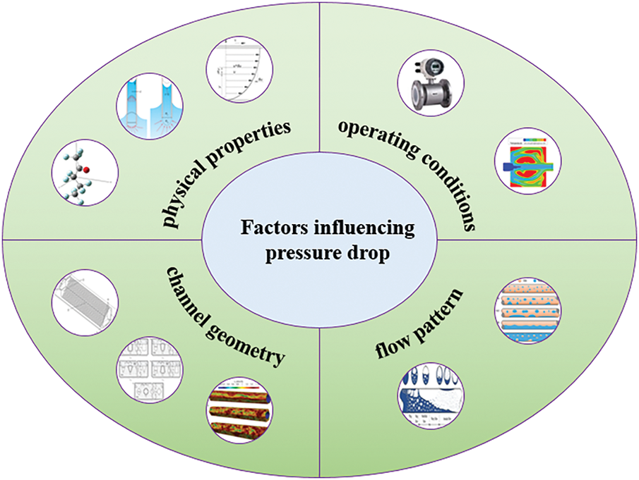
Figure 1: Factors influencing pressure drop of two-phase flow
2.1 Effect of Fluid Physical Properties on Pressure Drop
The physical properties of fluids are core influencing factors for two-phase flow pressure drop characteristics, with complex mechanisms closely coupled to flow patterns and operating conditions. Fluid physical properties include density, viscosity, and surface tension.
The influence mechanism of density is primarily reflected in the interphase slip effect (density differences between two phases lead to velocity differences, directly affecting momentum exchange and frictional pressure drop—the larger the density difference, the more significant the slip effect) and the roles of inertial and gravitational forces (the higher-density liquid phase has greater inertia, potentially intensifying flow separation; in vertical channels, density differences also affect the gravitational pressure drop component). Pamitran et al. [10] conducted experiments with five different working fluids (R-22, R-134a, R-410A, R-290, and R-744) in microchannels, showing that a larger liquid-to-vapor density ratio (
In actual operating conditions, density, viscosity, and surface tension often act together, so the coupling of multiple physical properties of the working fluid must be considered when analyzing pressure drop characteristics. Pamitran et al. [10] found in their experimental research that density, viscosity, and surface tension collectively determine the two-phase flow pressure drop characteristics by influencing fluid flow regimes, interphase friction, and flow pattern transitions.
Although many scholars have studied the effects of fluid physical properties on pressure drop characteristics, current research has rarely addressed pressure drop behavior under extreme property conditions, such as ultra-low surface tension (e.g., supercritical CO2), ultra-high viscosity (e.g., molten glass), and dynamic property changes (thermophysical parameters changing dynamically due to temperature or pressure variations). Ehsan et al. [14] investigated the pressure drop characteristics of supercritical CO2 and found that when it approaches the critical temperature, its thermophysical properties change drastically, leading to a sharp increase in pressure drop.
2.2 Effect of Operating Conditions on Pressure Drop
Operating conditions are dynamic control factors for two-phase flow pressure drop characteristics, whose changes significantly alter flow regimes, interphase interactions, and flow pattern distributions, thereby influencing the magnitude and fluctuation characteristics of pressure drop. Key operating conditions include mass flow rate, quality, heat flux density, and inlet subcooling.
Mass flow rate dominates changes in frictional pressure drop: an increase in mass flow rate typically raises flow velocity, with frictional pressure drop increasing with the square of velocity (especially in the turbulent region). Additionally, mass flow rate induces flow pattern transitions: high flow rates may drive flow patterns from stratified flow to annular or dispersed flow, altering pressure drop characteristics. Finally, in vapor-liquid two-phase flow, acceleration differences (slip velocity) between vapor and liquid phases at high flow velocities lead to additional acceleration pressure drop. Xu et al. [15] found that in the high Martinelli parameter region, enhanced interfacial interactions at low mass flow rates increase pressure drop. Furthermore, at low mass flow rates, two-phase flow tends to form liquid film flow and bubbly flow, which exhibit small interfacial fluctuations and low pressure drop; high mass flow rates promote transitions to slug or annular flow, enhancing interphase shear forces and void fraction, thereby increasing pressure drop.
As shown in Fig. 2, from Fazelnia et al. [16] boiling and condensation experiments of R1234yf in horizontal smooth circular tubes, it can be found that the increase of mass velocity and average vapor quality will significantly increase the pressure drop. However, pressure drop does not exhibit a linear relationship with quality: at low quality, the vapor phase is dispersed in the liquid phase, and frictional pressure drop increases with quality; at high quality, the vapor phase becomes the continuous phase, and frictional pressure drop may decrease. Mattiuzzo et al. [17] studied the effect of quality on pressure drop characteristics using mixtures of R513A and R516A refrigerants, finding that pressure drop first increases and then decreases with increasing quality, with a peak at x = 0.85–0.9. Song et al. [18] attributed the frictional pressure drop increase with quality to the rise in void fraction, which forms thinner liquid films on the channel wall. At constant mass flow rate, increasing void fraction reduces the average density of both liquid and vapor phases, leading to higher average velocity and increased pressure drop. In contrast, Del Col et al. [19] observed that increasing quality reduces pressure drop, as beyond a certain quality, flow transitions from annular flow to dry-out flow, decreasing the contact area between the liquid phase and the channel wall and thus reducing pressure drop. Additionally, quality changes directly affect other operating conditions. Yang et al. [20] found that for a working fluid at a specific quality, pressure drop decreases with increasing saturation pressure and increases with increasing mass flow rate. The effect of saturation pressure on pressure drop becomes more significant as quality increases, while the effect of mass flow rate weakens at higher saturation pressures. This is because at high saturation pressure, the vapor phase has higher viscosity and density, reducing vapor velocity under the same mass flow rate and quality—vapor-phase pressure drop decreases with lower vapor velocity, and the vapor phase’s viscosity and density also weaken the influence of mass flow rate on vapor velocity, with vapor-phase pressure drop often being the dominant component of two-phase flow pressure drop. Wang et al. [21] investigated the effects of mass flow rate and quality on pressure drop using air and water as working fluids. As shown in Fig. 3, pressure drop increases with both mass flow rate and quality, but increasing mass flow rate suppresses the growth rate of pressure drop. Conversely, higher quality promotes a faster growth rate of pressure drop. When quality increases from 0.40 to 0.48, 0.30 to 0.40, and 0.19 to 0.27, the frictional pressure drop gradients increase from 40.78 Pa∙m−1 to 69.75 Pa∙m−1, 25.62 Pa∙m−1 to 57.23 Pa∙m−1, and 21.18 Pa∙m−1 to 84.58 Pa∙m−1, respectively.
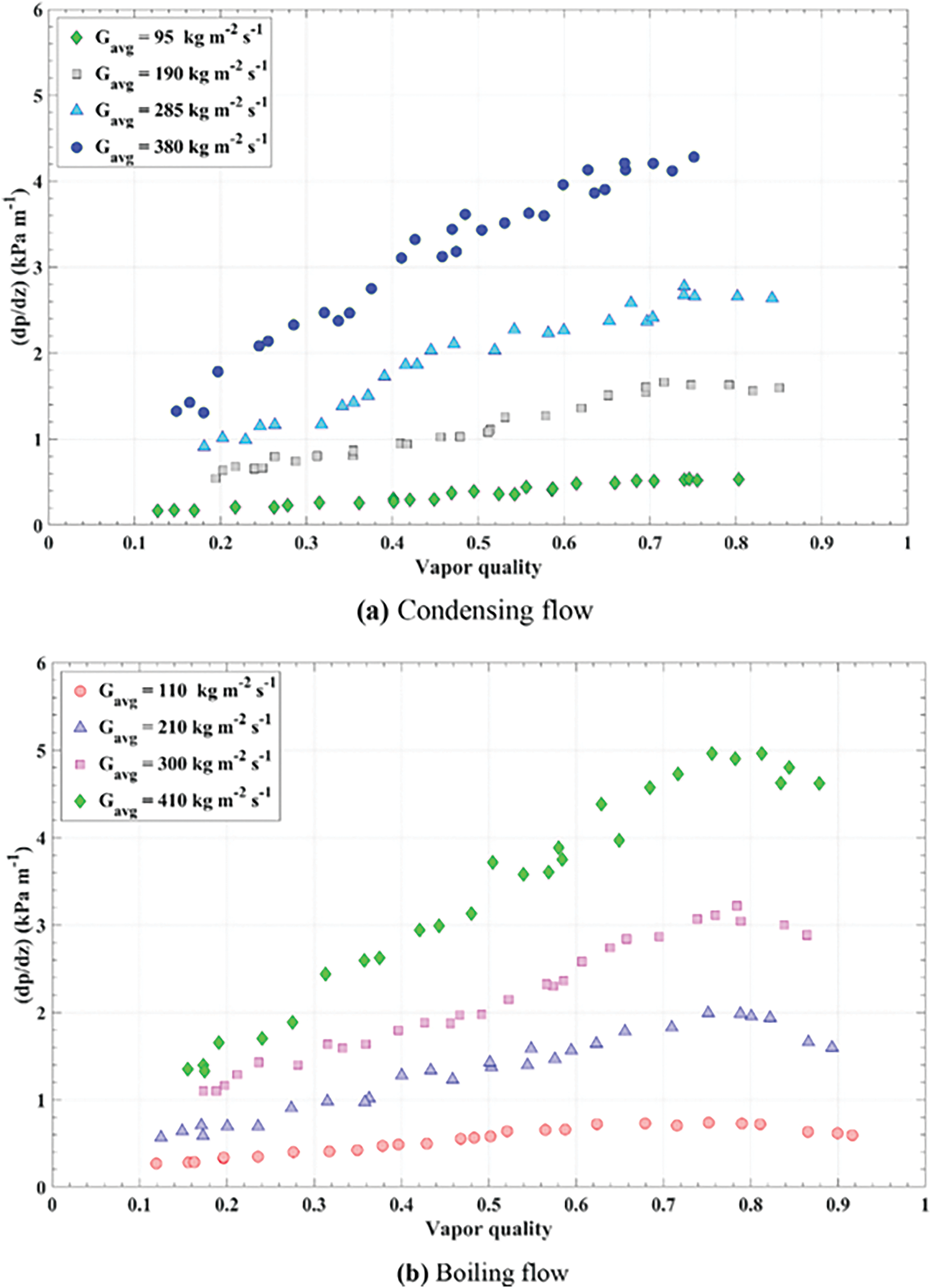
Figure 2: The effect of mass velocity and average vapor quality on the frictional pressure drop of (a) the condensing flow, and (b) the boiling flow [16]
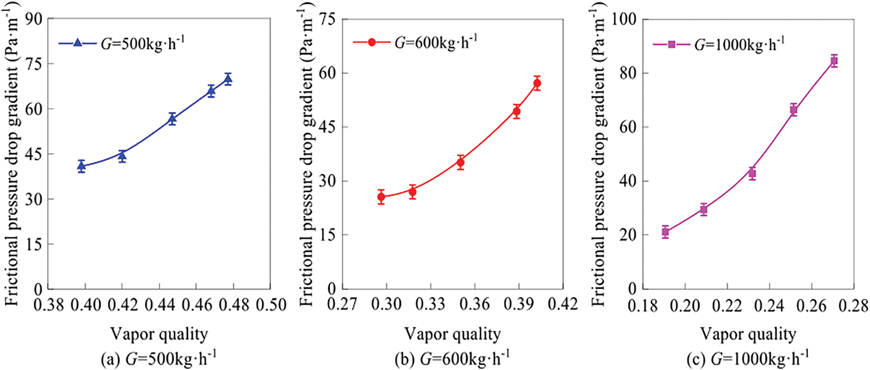
Figure 3: Pressure drop vs. dryness at different mass flow rates [21]. (a) G = 500
High heat flux density promotes bubble nucleation and growth, potentially triggering flow pattern transitions and intensifying pressure drop fluctuations. It also induces dynamic changes in local quality due to localized evaporation caused by heating, leading to non-uniform quality distribution along the flow direction and spatial non-uniformity in pressure drop. Rapid heating may also create temperature differences between vapor and liquid phases, affecting physical properties and indirectly altering the pressure drop. Tibirica and Ribatski [22] found that increasing heat flux density enhances vaporization rate and quality, thereby increasing pressure drop. Xu and Yu et al. [23,24], however, observed that at a constant quality, heat flux density has little effect on pressure drop—while the liquid film vaporization rate is proportional to heat flux, its increase is much smaller than the corresponding quality change. Li and Fang [25] demonstrated that higher heat flux intensifies nucleate boiling, increasing bubble generation and departure frequency in the tube. The increased number of bubbles amplifies fluid density gradients, accelerating a significant rise in pressure drop; moreover, bubble disturbances enhance wall friction, further increasing frictional pressure drop. Consequently, the total pressure drop exhibits a pronounced upward trend with increasing heat flux density.
When the inlet subcooling is large, the working fluid needs to absorb more heat before entering the heating zone to reach saturation, thereby delaying the onset of boiling—a phenomenon known as boiling hysteresis. During the boiling hysteresis stage, the working fluid mainly flows as a single phase, resulting in relatively small pressure drop. As the heat flux density increases, the fluid gradually transitions into a two-phase flow regime, and the pressure drop begins to increase significantly. Li and Fang [25] showed that low inlet subcooling shortens the single-phase flow region, causing the working fluid to enter the two-phase flow stage earlier, thus generating a larger total pressure drop under the same heat flux density. Increasing inlet subcooling also affects two-phase flow pattern transitions. At lower inlet subcooling, the working fluid more easily enters the two-phase flow state, with flow patterns potentially transitioning from bubbly flow to slug flow, annular flow, etc. Different flow patterns exhibit distinct pressure drop characteristics: bubbly flow has relatively small pressure drop, while slug and annular flows have larger pressure drops. In microchannel flow boiling experiments, Xie et al. [26] found significant differences in two-phase pressure drop during bubbly, slug, and annular flow stages under different inlet subcooling conditions. In the bubbly flow stage, bubble generation is relatively low, with bubbles isolated from each other, leading to small frictional resistance. In the slug and annular flow stages, the velocity difference between vapor and liquid phases increases, causing a higher along-the-channel pressure drop.
Operating conditions exert multi-dimensional influences on two-phase flow pressure drop by directly altering flow regimes and phase-change processes. Future research should focus on breaking through the quantitative analysis of multi-condition coupling mechanisms and dynamic responses, providing precise design guidelines for complex engineering applications in two-phase flow thermal management.
2.3 Effect of Flow Channel Geometry on Pressure Drop
The geometric structure of the flow channel is a key design parameter for two-phase flow pressure drop characteristics, directly influencing flow resistance, flow pattern evolution, and the intensity of interphase interactions.
The inner diameter affects the flow velocity and shear force in the channel: a smaller inner diameter increases flow velocity (at the same mass flow rate), enhances wall shear stress, and significantly raises frictional pressure drop. In microchannels, the effect of surface tension is also amplified, making flow patterns more prone to bubbly or annular flow, with pressure drop characteristics deviating from conventional correlations. Additionally, the proportion of the flow development section is larger in microchannels, leading to a steeper local pressure drop gradient. Pamitran and Revellin et al. [10,27] studied the pressure drop characteristics of refrigerants R134a and R245fa in micro-sized channels and found that smaller channel diameters result in higher pressure drops. This is because a reduced inner diameter increases wall shear force, leading to a higher friction coefficient and correspondingly higher pressure drop. Pamitran et al. [10] tested the boiling flow of R22 in a horizontal circular channel. At a mass flow rate of 500 kg/m2·s, the pressure drop increased from 31 to 37.2 kPa/m when the inner diameter decreased from 3.0 to 1.5 mm.
The cross-sectional shape affects the pressure drop distribution. In non-circular cross-sections (such as rectangular, triangular, and flat tubes), secondary flows or stagnant areas are likely to form in the corner regions, increasing the effective frictional resistance. Kim and Mudawar [28] established a detailed analysis model for microchannel heat sinks with rectangular, inverted trapezoidal, triangular, trapezoidal, and rhombic cross-sections. Rectangular microchannels generally have lower flow resistance due to their symmetry and relatively large flow cross-sectional area. Inverted trapezoidal, triangular, trapezoidal, and rhombic microchannels may lead to higher flow resistance because of sharp corners, variable cross-sections, or smaller flow areas. The cross-sectional shape also affects the morphology of the vapor-liquid interface. In flat tubes, the liquid phase wets the upper and lower walls more easily, forming a thin liquid film, and the pressure drop is dominated by the shear force of the liquid film. In addition, changes in the aspect ratio of the rectangular cross-section will also affect the flow structure. Tutwiler et al. [29] found that twisted elliptical tubes with different aspect ratios can induce stronger swirling flows and small-scale turbulent structures (Fig. 4), resulting in enhanced flow mixing and thus increasing the flow resistance. An increase in the aspect ratio also leads to a nonlinear increase in the friction coefficient, thereby increasing the pressure drop. Existing correlations do not consider the influence of the aspect ratio, so there are deficiencies in predicting the pressure drop in the case of different aspect ratios. In addition, fluids with a low Prandtl number (such as liquid metals) have a smaller change in pressure drop when the aspect ratio changes, while fluids with a high Prandtl number (such as water or oil) show a more obvious change.
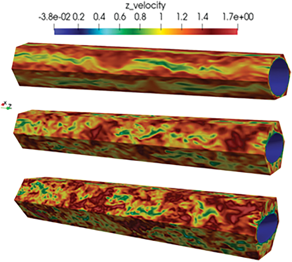
Figure 4: Twisted elliptical tubes with different aspect ratios [29]
Zhang et al. [30] studied the characteristics of subcooled flow pressure drop in manifold microchannel heat sinks and found that as the aspect ratio (height-to-width ratio) of the microchannels increased (for example, from 6.67 to 16.67), the pressure drop decreased significantly. This is because an increase in the aspect ratio leads to an increase in the cross-sectional area and a decrease in the flow velocity, thereby reducing the frictional pressure drop.
In complex two-phase loop systems, local structures such as elbows and T-joints may also induce secondary flows and phase separation, resulting in additional local pressure drops [31]. Wang et al. [32] used numerical simulations to explore the influence of the pipe diameter of right-angle elbows on local pressure drops. The research results show that right-angle elbows are the main parts contributing to the local pressure drop losses of coupling pipe fittings, and their pressure drop losses account for two-thirds of the entire coupling pipe fittings. On the other hand, Wang focused on exploring the influence of 90° bends on the pressure distribution of different vapor-liquid two-phase flows for specific vapor-liquid two-phase flow patterns in vertical upward pipes. It was found that different vapor-liquid two-phase flow patterns would generate secondary flow phenomena to varying degrees after passing through a 90° bend. The tangential velocity at the outlet of the bend presents a bimodal distribution, which eventually dissipates into a unimodal distribution as the flow develops. Muzaffar et al. [33] also found that in microchannels with a small bend ratio, the centrifugal force is enhanced, the flow separation is intensified, and the pressure drop increases significantly.
In summary, the geometric shape of the channel mainly regulates the flow resistance and flow pattern distribution directly through geometric constraints, thereby determining the characteristics of two-phase flow pressure drop. The main challenges faced by current research lie in the lack of a universal model for the pressure drop characteristics of asymmetric and irregular cross-sections (such as honeycomb structures and porous media), which requires a combination of topological optimization and experimental calibration. In addition, flexible channels (such as biological blood vessels and flow channels of soft robots) deform during flow, resulting in a nonlinear coupling of pressure drop, and existing rigid models are not applicable.
2.4 Effect of Flow Pattern on Pressure Drop
Flow pattern refers to the spatial distribution of vapor and liquid phases in two-phase flow, which directly determines the interphase force and pressure drop characteristics. The dominant mechanisms of pressure drop vary significantly under different flow patterns, and dynamic transitions between flow patterns can lead to drastic fluctuations in pressure drop. As shown in the figure, two-phase flow patterns are mainly classified into bubbly flow, slug flow, stratified flow, annular flow, and mist flow. The main factor influencing the flow pattern is the quality x of the two-phase flow. Gao et al. [34] conducted experimental research on the flow boiling of liquid nitrogen in microchannels: Bubbly flow mainly occurs when x < 0.2, slug flow appears when 0.1 < x < 0.4, stratified flow occurs when x > 0.4, annular flow is present when x > 0.6, and mist flow occurs when x > 0.8. The flow patterns are schematically shown in Fig. 5. The main characteristic of slug flow is high-frequency pulsating fluctuations, and its average pressure drop increases with the increase of quality. This is mainly because the periodic formation and release of large bubbles lead to local flow blockage, causing alternating changes between acceleration pressure drop and frictional pressure drop. In stratified flow, the liquid phase and the vapor phase flow in layers, and the interfacial friction is relatively small, but when the velocity of the vapor phase is high, the total pressure drop increases. Therefore, the pressure drop is relatively stable, with frictional pressure drop being the main component, and an increase in vapor velocity will intensify the friction and acceleration pressure drop. In annular flow, the high-speed flow of the central vapor phase and the friction with the outer liquid phase act together. Due to the low density of the vapor phase, its velocity is higher than that of the liquid phase, resulting in an increase in both acceleration pressure drop and frictional pressure drop. The pressure drop of mist flow increases significantly with a further increase in vapor quality, and a sudden rise in the wall temperature after dryout may lead to local flow instability. In addition, the frictional pressure drop of bubbly flow is similar to that of single-phase flow, but due to the enhanced turbulence caused by bubble disturbances, the pressure drop is slightly higher, and the coalescence or fragmentation of bubbles will also slightly change the pressure drop gradient.
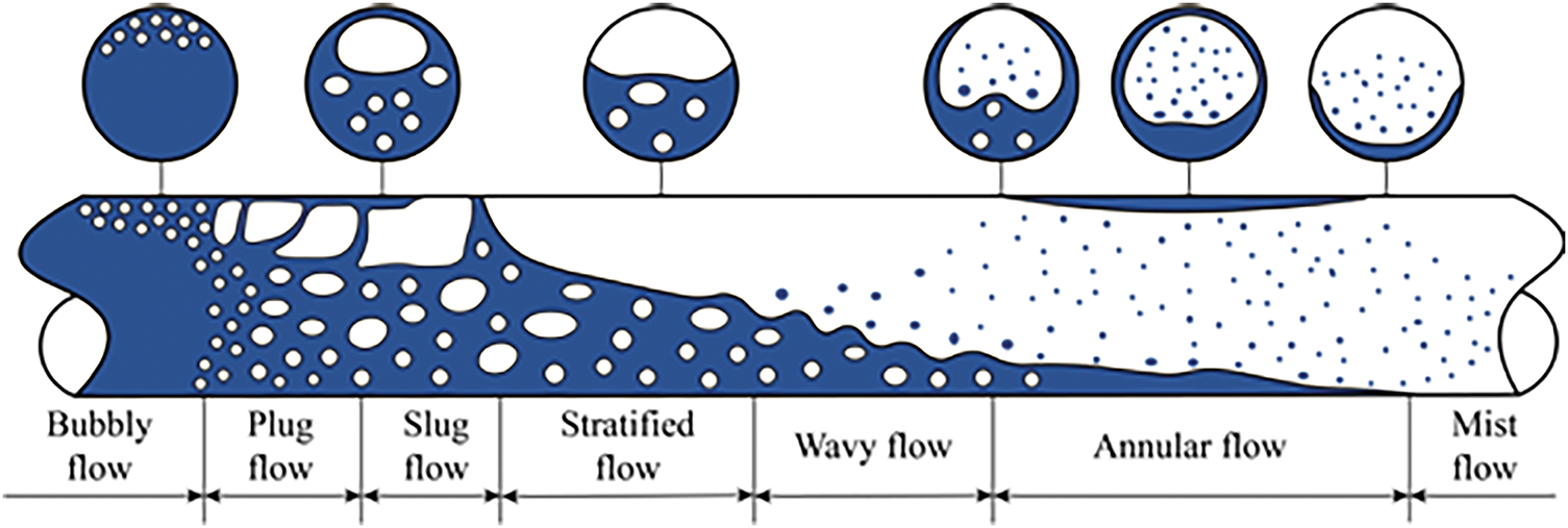
Figure 5: Flow pattern [34]
Flow patterns become the core regulating factors for two-phase flow pressure drop by changing the influencing proportions of frictional, acceleration, and gravitational pressure drops. Due to the significant differences in the flow characteristics and pressure drop characteristics among various flow patterns, many scholars currently establish pressure drop models for two-phase flow based on these flow patterns.
Studying the characteristics of pressure drop holds significant engineering implications in aspects such as engineering design and optimization, energy utilization and energy conservation, as well as flow state and control. The prediction and control of two-phase flow pressure drop are key issues for improving the performance of microchannel heat exchangers. Its influencing factors mainly include fluid physical properties, channel properties, operating conditions, and flow patterns. The interactions among these factors are complex, involving strong coupling of multiple physical fields such as fluid mechanics, thermodynamics, and heat transfer, which makes it difficult to describe them within a single theoretical framework. By clarifying the action boundaries and interaction mechanisms of each factor, scholars have taken the factors influencing two-phase flow pressure drop as variables and limiting conditions, and developed prediction models for two-phase flow pressure drop. They have gradually achieved the transition from local empirical modification to global mechanism modeling, thus laying a theoretical foundation for the efficient regulation of two-phase flow pressure drop in thermal control systems.
3 Study on Pressure Drop Model of Two-Phase Flow
Two-phase pressure drop models can be categorized into mathematical models and experimental models. Mathematical models are mainly based on fundamental theories such as fluid mechanics and thermodynamics. They describe the flow characteristics and pressure drop patterns of two-phase flow by establishing mathematical equations. Experimental models are established and validated through a large amount of experimental data, directly reflecting the pressure drop patterns under actual flow conditions. Once a mathematical model is established and verified, it can be popularized and applied within a certain range to predict the two-phase flow pressure drop under different operating conditions, but its prediction accuracy cannot be guaranteed. Experimental models can be studied for specific fluids, pipeline conditions, and operating parameters, and can more accurately reflect the flow characteristics under specific circumstances. However, the establishment of experimental models is often based on very limited experimental data. Various models do not have relatively accurate calculation accuracy within all parameter ranges and are usually applicable within a limited range of conditions. As shown in Fig. 6, numerous methods for predicting two-phase flow pressure drop have been proposed by researchers. Among these, the homogeneous flow model, separated flow model, and certain flow-pattern-based methods are widely recognized. Lately, machine learning approaches have also drawn growing attention. This is mainly because they can conduct multiple nonlinear regressions, which is beneficial for predicting pressure drop.
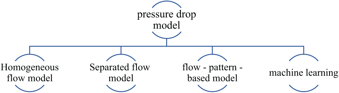
Figure 6: Pressure drop model of two-phase flow
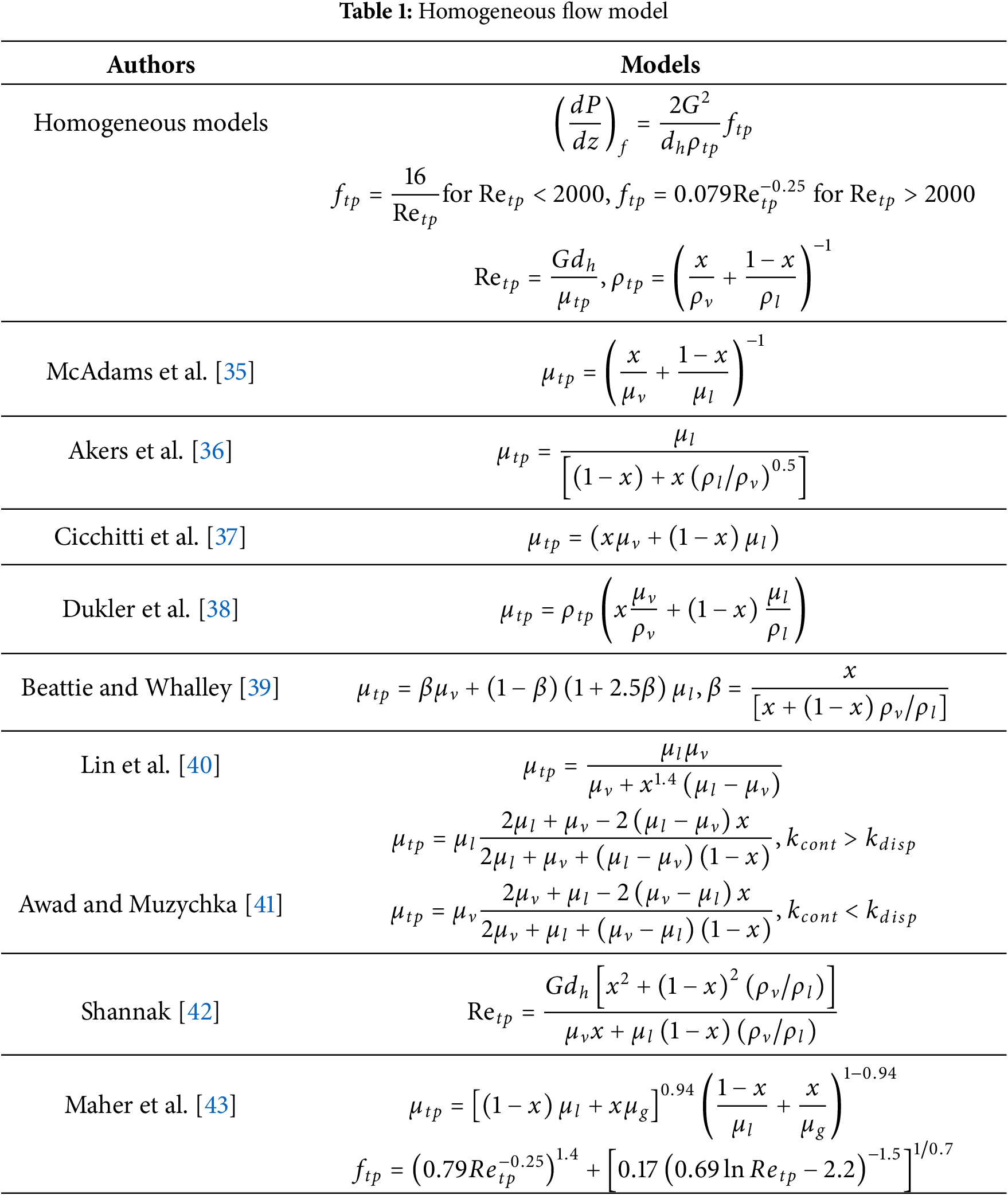
The homogeneous flow model is the simplest two-phase flow analysis model. Its core assumptions are that the vapor and liquid phases are uniformly mixed, there is no relative velocity between them, and the two phases are in a state of thermodynamic equilibrium. The homogeneous flow model treats two-phase flow as having the characteristics of a mixed fluid by utilizing the density and viscosity of the two-phase mixture, and simplifies calculations by defining the average physical property parameters (such as density and viscosity) of the mixture. In 1949, McAdams et al. [35] first proposed a simple two-phase viscosity expression by making an analogy with the two-phase density. Subsequently, Akers et al. [36] and Cicchitti et al. [37] developed their own two-phase viscosity expressions based on the experimental results of the flow boiling of water and steam. Dukler and Wicks [38] proposed introducing the average value of kinematic viscosity and put forward a new two-phase viscosity equation. The two-phase viscosity equation proposed by Beattie and Whalley [39] combines the characteristics of bubbly flow (based on Einstein’s theory) and annular flow (based on the assumption of interfacial wave intermittency), and is applicable to complex flow patterns dominated by gravity. Lin et al. [40] proposed a local two-phase frictional pressure drop prediction model for R12 in microchannels. The model introduces the 1.4th power of the mass vapor void fraction x, weakening the contribution of the liquid phase viscosity in the region with a high vapor void fraction, so that the prediction results are more consistent with the flow characteristics with a low slip ratio (Sc < 2) in the capillary tube. For different two-phase flows, Awad and Muzychka [41] proposed two new two-phase viscosity models by using the Maxwell-Eucken 1 and 2 models to make an analogy with the effective thermal conductivity. Maxwell-Eucken 1 is suitable for materials in which the thermal conductivity of the continuous phase is higher than that of the dispersed phase (kcont > kdisp), such as foams or sponges, while Maxwell-Eucken 2 is suitable for materials in which the thermal conductivity of the continuous phase is lower than that of the dispersed phase, such as particulate materials. Therefore, the former is suitable for two-phase flows in which the continuous phase is the liquid phase, such as bubbly flow; and the latter is suitable for two-phase flows in which the continuous phase is the vapor phase, such as mist flow. Shannak [42] synthesized the inertial force (in the numerator) and viscous force (in the denominator) of the vapor-liquid two phases and proposed a new two-phase Reynolds number expression, which more accurately reflects the momentum transfer characteristics of two-phase flow. Maher et al. [43] proposed a new viscosity expression based on the analogy of porous media. This formula combines the parallel model of Cicchitti et al. [37] and the series model of McAdams et al. [35] through exponential weighting (0.94), balancing the viscosity contributions under different flow conditions. In addition, they also proposed a new friction factor formula, which combines the Blasius equation (for turbulent flow) and an empirical term, covering the entire range from laminar flow to turbulent flow and avoiding the discontinuity of traditional models in the transition region. Table 1 lists the comparison of homogeneous flow models by different scholars.
The homogeneous flow model treats two-phase flow as a uniform mixture and describes the flow characteristics using the average density and viscosity. It is applicable to flow patterns such as bubbly flow and annular flow, and performs particularly well under conditions of high vapor void fraction or turbulent flow. However, since it does not take into account the velocity difference between the vapor and liquid phases and the interfacial shear force, it leads to large prediction deviations at low qualities. In microchannels, the flow is dominated by surface tension, but the homogeneous flow model fails to effectively incorporate parameters related to surface tension. In addition, for subcooled boiling, the dynamic changes in bubble generation and condensation are complex, and the homogeneous flow model is unable to accurately capture these phenomena.
The separated flow model calculates the effects of the liquid and vapor phases separately through their respective friction coefficients. Dimensionless parameters (such as the Lockhart-Martinelli parameter X, the Chisholm parameter C, and the Bond number) are introduced to describe interphase interactions and surface tension. In 1949, Lockhart [44] first proposed the concepts of the liquid-phase and vapor-phase friction coefficients
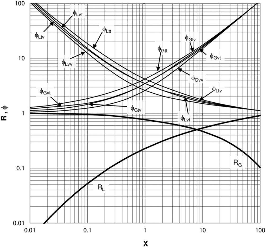
Figure 7: Lockhart and martinelli four flow patterns [44]
To facilitate scholars’ use and calculations, Chisholm [45] proposed a creative approach to establish the relationship between the liquid-phase friction coefficient
In addition to modifying the pressure drop coefficient C, many scholars have also optimized the Lockhart-Martinelli liquid-phase friction coefficient, pressure drop expression, and friction factor f. Muller-Steinhagen and Heck [51] simplified the original pressure drop expression. Compared with complex empirical models, this formula features a simple form and eliminates the need for iterative calculations, making it suitable for rapid engineering estimations.
Tao and Ferreira [52] modified the Lockhart-Martinelli model for NH3 in plate heat exchangers. The new model adds an
Sun et al. [53] found that existing models are insufficient for predicting flow boiling pressure drop in rectangular channels—the predictions of the homogeneous model using the equivalent viscosity assumption were significantly lower than experimental values, with large data dispersion. They therefore conducted a study on pressure drop characteristics during flow boiling under uniform and non-uniform transverse wall heating in a vertical rectangular channel. Based on experimental data, they evaluated the applicability of existing correlations and proposed a new model based on Muller-Steinhagen-Heck model, introducing the Bond number to account for the effect of surface tension.
Hao et al. [54] conducted research on the pressure drop characteristics of CO2 in horizontal heated tubes, exploring pressure drop models under subcritical and supercritical pressures respectively. They found that the commonly used Chisholm and Friedel correlations under subcritical conditions, which are based on data for water and conventional refrigerants, cannot accurately predict the subcritical pressure drop of CO2. To address this, they modified the Chisholm and Friedel correlations and established new friction factor correlations, significantly improving the prediction accuracy.
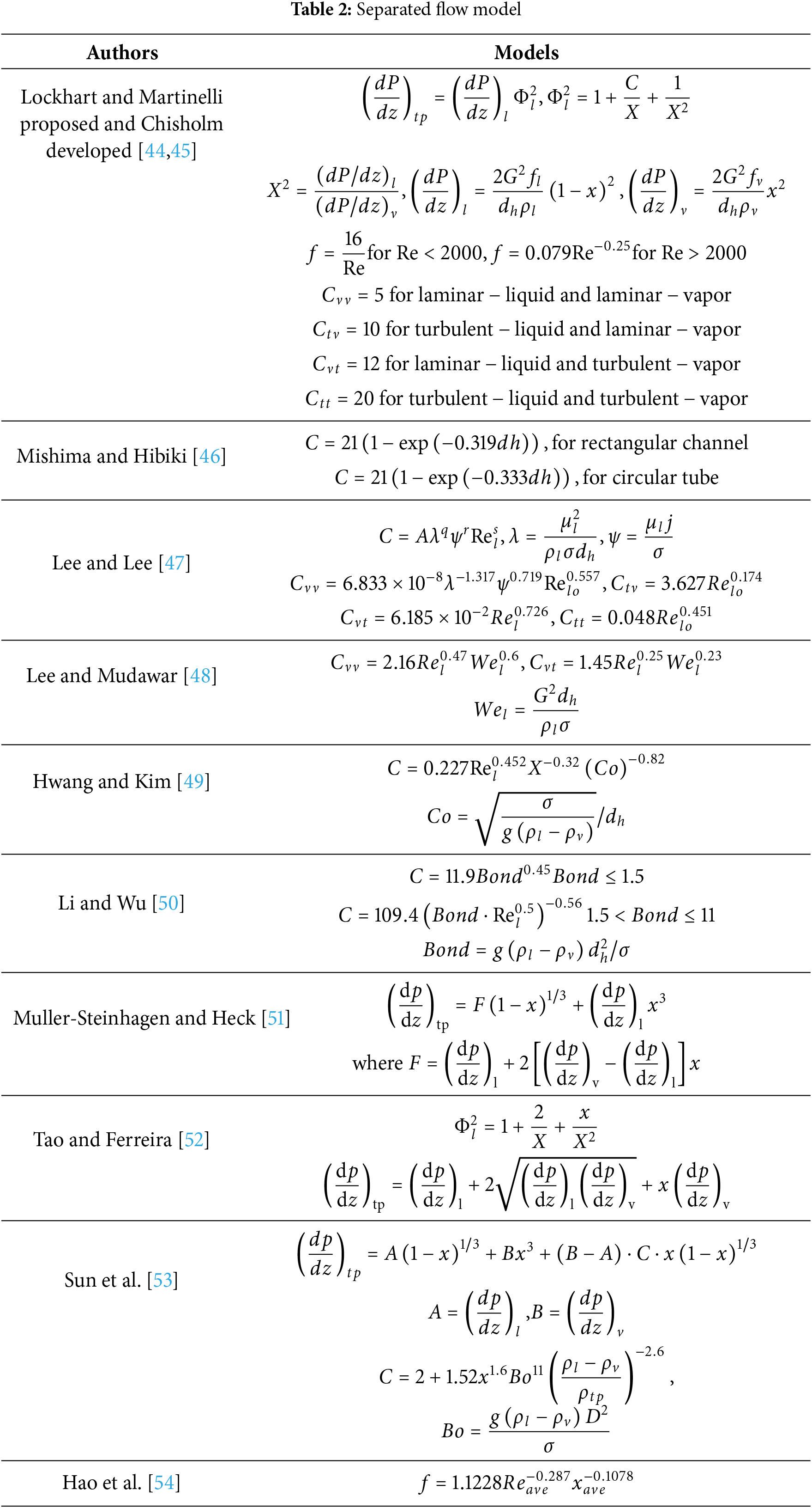
The classical separated flow models (Lockhart-Martinelli and Chisholm) address interphase interactions through liquid-phase and vapor-phase friction coefficients and dimensionless parameters. However, these models were developed based on macrochannels and do not fully account for the dominant characteristics of surface tension and viscous forces in microchannels. Building on these models, researchers have incorporated microscale effects such as surface tension, viscous forces, and the gas-liquid density ratio in microchannels by modifying the pressure drop coefficient C and introducing new dimensionless numbers like the Bond number (Bo) and Weber number (We). Many researchers have also revised the separated flow models for specific working fluids and operating conditions, enabling them to better adapt to particular environments and significantly improving the prediction accuracy. Table 2 lists the comparison of separated flow models by different scholars.
3.3 Pressure Drop Model Based on Flow Pattern
In addition to the homogeneous flow model and the separated flow model, some scholars have established different pressure drop correlations based on flow patterns (such as bubbly flow, slug flow, and annular flow). Flow pattern-based models mainly refer to those that consider the influence of different flow patterns on pressure drop. These models typically analyze the structure of the gas-liquid interface and use different parameters and empirical values to predict pressure drop according to the specific flow pattern. Moreno Quibén and Thome [55] proposed a new method for predicting two-phase frictional pressure drop, which accounts for the interfacial effects between phases and was developed using a phenomenological approach. The new model processes each flow pattern separately, ensuring smooth transitions at the transition boundaries and consistency with experimental results. Harirchian and Garimella [56] studied the fluorinated liquid FC-77 in microchannels where multiple flow patterns coexist and developed a new flow pattern-based pressure drop model. They divided the microchannel into single-phase, bubbly flow, slug flow, and annular flow regions, calculating the pressure drop for each section and then summing them up. As shown in the Fig. 8, Harirchian identified two main flow conditions in microchannels: confined flow and unconfined flow. The total pressure drop for confined flow is the sum of the pressure drops in the single-phase region, slug flow region, and annular flow region; for unconfined flow, it is the sum of the pressure drops in the single-phase region, bubbly flow region, and annular flow region.
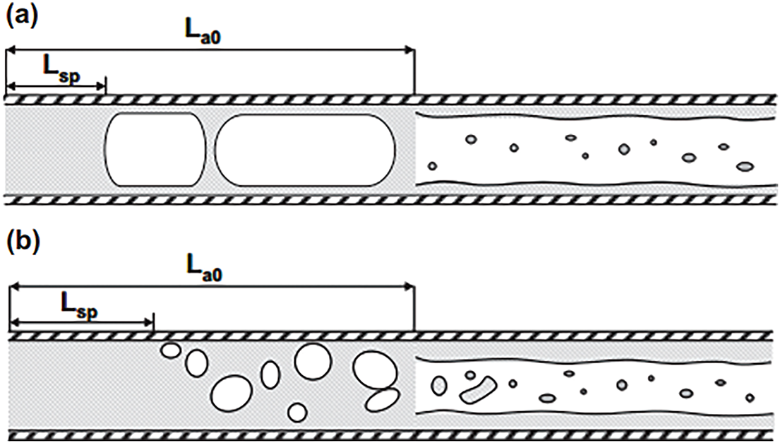
Figure 8: Flow diagram of confined flow (a) and unconfined flow (b) [56]
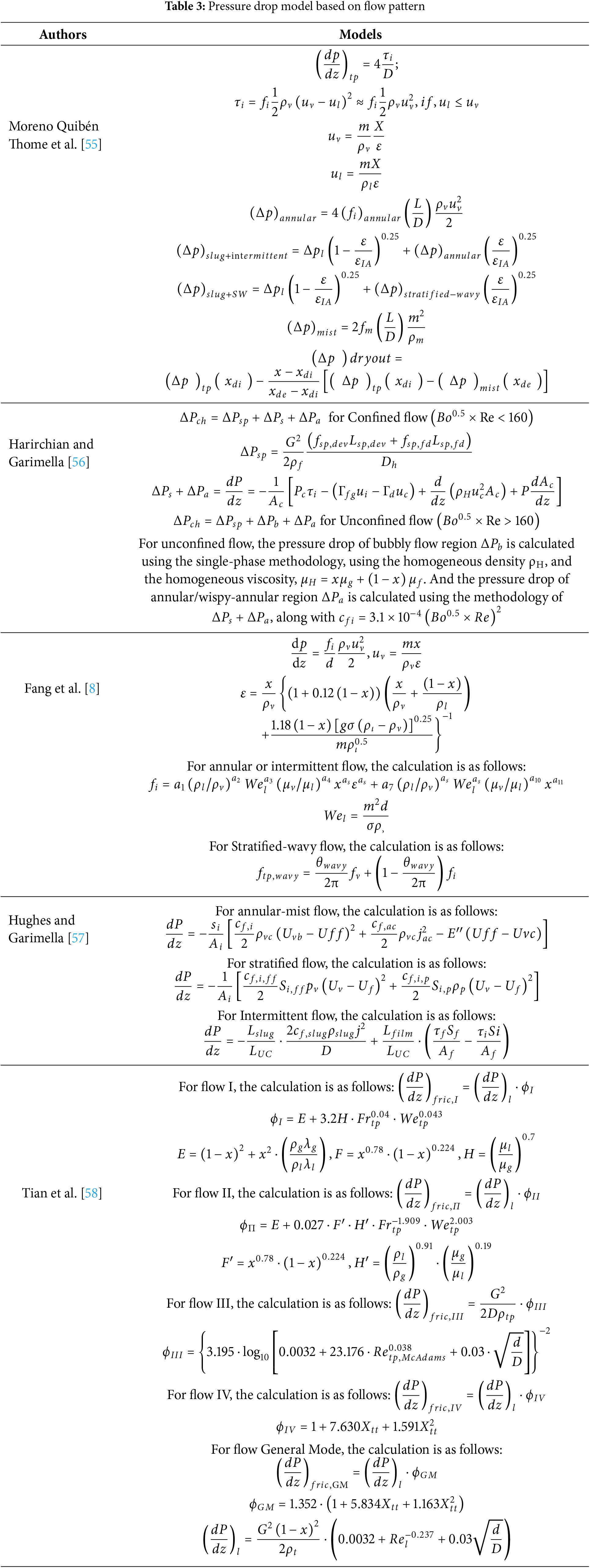
Fang et al. [8] believed that Thome’s model required distinguishing multiple flow patterns, leading to complex calculations and strong subjectivity in classification. They therefore simplified flow patterns into two forms: annular/intermittent flow and wavy/stratified flow, reducing the complexity of flow pattern classification, ensuring model continuity, and making it more suitable for engineering applications. Hughes and Garimella [57] divided two-phase flow into three patterns: annular mist flow, stratified flow, and intermittent flow, establishing independent pressure drop models for each. Additionally, Matthew incorporated the influence of acoustic excitation into flow pattern criteria and flow mechanisms. Through visualization experiments, Tian et al. [58] classified flow patterns in helical tubes into four types: bubble flow, intermittent flow, wavy-stratified flow, and annular flow (as shown in Fig. 9). They proposed differentiated frictional pressure drop models for different flow patterns and finally developed a unified formula covering all flow patterns, suitable for simplified engineering calculations. Table 3 lists the comparison of pressure drop model based on flow pattern by different scholars.
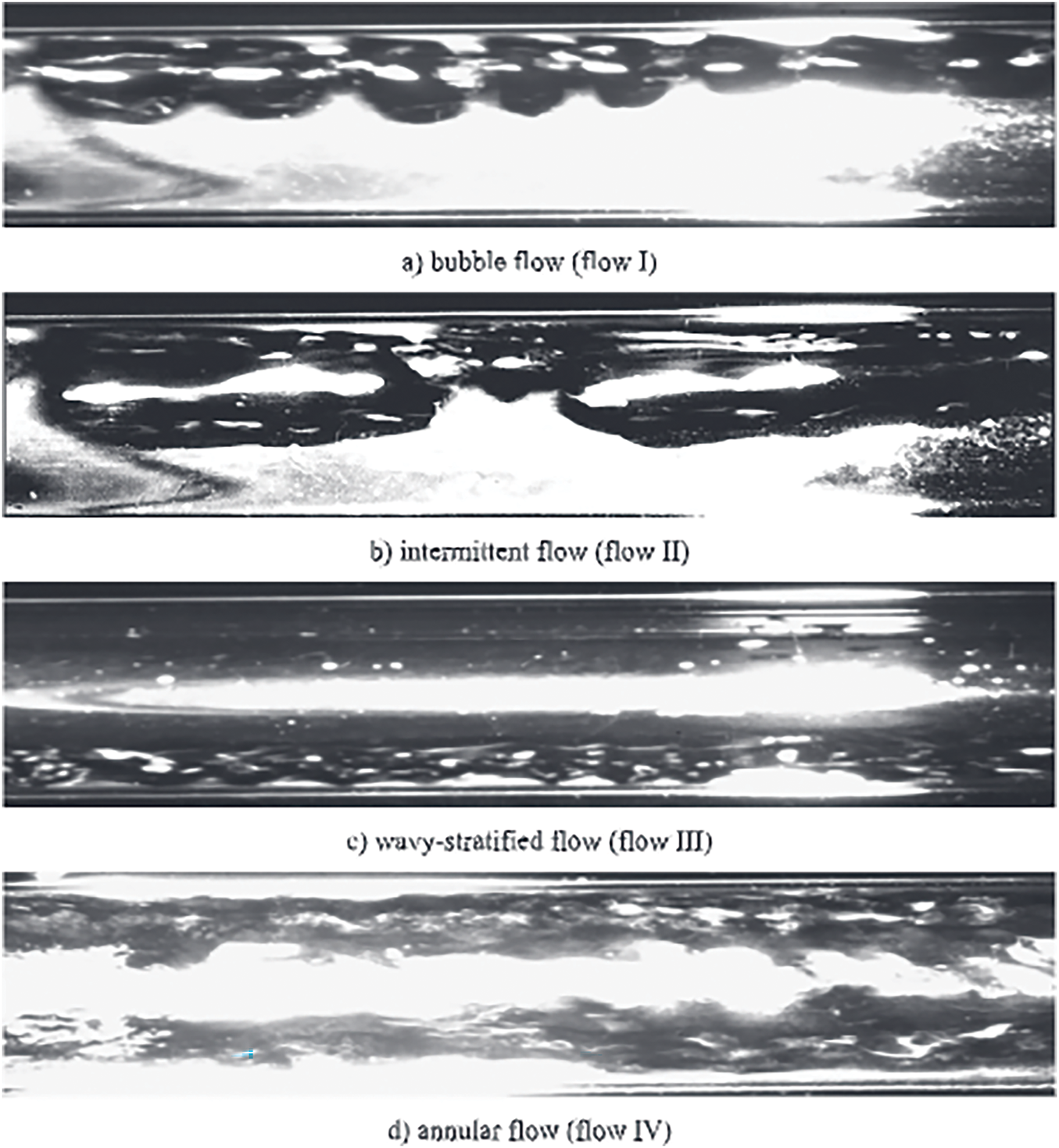
Figure 9: Classification of flow patterns in helical tubes [57]. (a) Bubble flow, (b) intermittent flow, (c) wavy-stratified flow, and (d) annular flow
Flow pattern-based pressure drop prediction models can establish corresponding pressure drop calculation methods according to the characteristics of different flow patterns, thereby more accurately characterizing the flow state of gas-liquid two-phase in pipelines and improving the accuracy of pressure drop prediction. In addition, flow pattern-based prediction methods can predict flow pattern transitions based on changes in operating parameters and perform corresponding pressure drop predictions using pressure drop calculation formulas for different flow patterns. This avoids the issue of insufficient prediction accuracy of a single model across the entire operating range and further enhances the accuracy of pressure drop prediction. However, this approach has problems such as disagreements among scholars on flow pattern classification, over-simplification of complex flow mechanisms in models, and high dependence on experimental data.
3.4 Application of Machine Learning in Pressure Drop Prediction Models
The application of machine learning in two-phase flow pressure drop prediction has become a hot research direction in the fields of fluid mechanics and energy engineering in recent years. Traditional methods rely on empirical formulas or physical models, but they are limited by complex flow regimes and nonlinear factors. In contrast, machine learning significantly improves prediction accuracy and generalization ability through data-driven approaches. ANN (artificial neural network) has powerful nonlinear fitting capabilities and can automatically learn the complex relationships between input parameters and pressure drop. Mudawar et al. [9] found that traditional empirical correlations and theoretical models have large errors in predicting flow boiling pressure drop under microgravity, especially under complex operating conditions. Aiming at the shortcomings of traditional models, they developed a data-driven ANN model that uses a large-scale database from International Space Station (ISS) experiments to improve pressure drop prediction accuracy. The final test set MAE (mean absolute error) was 5.24%, far superior to traditional models. Qiu et al. [59] used dimensionless numbers as the input parameters for the ANN, which cover flow characteristics (such as mass velocity, gas void fraction), geometric parameters (such as hydraulic diameter), and fluid properties (such as density, viscosity), spanning a wide range of operating conditions.
SVM (support vector machine) achieves data classification or regression prediction by finding the optimal hyperplane. In two-phase flow pressure drop prediction, SVM can be used to establish a regression model between input parameters and pressure drop, optimizing model parameters through training datasets to improve prediction accuracy. Khosravi et al. [60] applied SVR (support vector regression), a regression analysis method based on SVM, to predict the pressure drop during the evaporation of R407C in horizontal smooth copper tubes. In addition to SVR, they also used algorithms such as multilayer feedforward neural networks (MLFFNN) and group method of data handling (GMDH). The combined use of the three algorithms avoids complex prior assumptions, automatically screens important features, reduces the risk of overfitting, and enhances model stability.
Extreme gradient boosting (XGBoost), an ensemble learning model based on gradient boosting, iteratively optimizes prediction residuals through multiple decision trees and excels in handling high-dimensional data and nonlinear relationships. Nie et al. [61] applied XGBoost and ANN algorithms to predict two-phase frictional pressure drop in horizontal pipes. XGBoost efficiently processes large-scale data, effectively improving training efficiency.
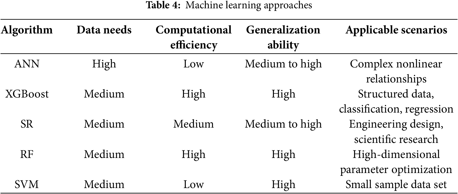
In addition, Yaqub and Chen [62] explored the application of SR (Symbolic Regression) in predicting the pressure drop of fluids at 90-degree bends. Compared to traditional CFD and empirical methods, SR is more accurate, computationally efficient, and interpretable. The unified SR model can handle various flow patterns without needing separate correlations for each, which is crucial for upstream pipeline design. Zhai et al. [63] examined the use of machine learning in predicting heat/mass transfer and pressure drop in microchannels, comparing it to traditional empirical correlations. Machine learning significantly improved prediction accuracy for Nu, Sh, and Fr, with the Random Forest (RF) model performing the best and enhancing accuracy by 12.37% to 30.47%. Table 4 shows a comparison of the algorithms.
By using machine learning, not only can it effectively predict pressure drop in complex flow regimes, but it can also automatically mine local flow characteristics. However, current machine learning still faces issues such as large noise in experimental data, black-box models being difficult to provide explanations for physical mechanisms, and insufficient prediction performance for conditions outside the training set.
Two-phase flow pressure drop models are key tools for predicting and controlling the performance of microchannel heat exchangers. Currently, scholars have proposed various models, including the homogeneous flow model, separated flow model, flow pattern-based models, and machine learning methods. The homogeneous flow model is applicable under certain specific conditions due to its simplicity, but it has limitations; the separated flow model improves prediction accuracy by considering interphase interactions, yet increases model complexity; flow pattern-based models can more precisely characterize pressure drop characteristics under different flow patterns, but the subjectivity and data dependence of flow pattern classification restrict their wide application; machine learning methods significantly enhance prediction accuracy and generalization ability through data-driven approaches, but still face challenges in explaining physical mechanisms and generalizing to new data. Future research needs to further improve the physical basis of the models, incorporate multi-physical field coupling effects, and enhance model accuracy and applicability. Meanwhile, it is necessary to explore more efficient methods for experimental data acquisition and processing to support continuous model optimization and practical engineering applications.
4 Optimization of Equilibrium Pressure Drop and Heat Transfer Characteristics
With the rapid development of electronic devices, miniaturization, lightweight, and high heat flux density have gradually become the goals pursued by electronic devices. The main challenge restricting the further development of electronic devices is currently the issue of heat dissipation. Improving the heat transfer coefficient of microchannels and reducing the pressure drop of the heat dissipation system are key to solving this problem. From the previous research, we know that pressure drop can be reduced through operating conditions (mass flow rate, quality, heat flux density, and inlet subcooling). However, adjusting operating conditions to reduce pressure drop often causes the heat transfer coefficient to change in the opposite direction. For example, reducing the mass flow rate to lower the pressure drop will also decrease the heat transfer coefficient in microchannels. In the optimization of two-phase flow heat dissipation systems, there is often a desire to improve heat transfer characteristics without incurring a larger pressure drop. As shown in Fig. 10, optimizing the microchannel structure and the flow distribution can effectively balance the pressure drop and heat transfer characteristics.
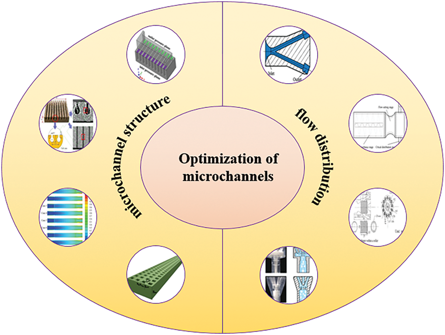
Figure 10: Optimization of microchannels
4.1 Optimization of the Microchannel Structure
Optimizing the microchannel structure is the main approach used in current research, which includes adding porous structures to the microchannel surface, filling the microchannel interior with porous materials, and replacing the microchannel framework with porous structures. Balancing the uneven flow distribution in microchannels can be achieved by improving the manifold that distributes fluid from the main channel to the branch channels. Porous structures can effectively expand the heat transfer area and enhance the heat transfer coefficient. They also provide micro-pores and space for bubble nucleation, thereby alleviating flow instability. Applying porous structures to microchannels can significantly enhance heat transfer. Zhou and Zhang [64] summarized microchannel heat dissipation technologies based on porous structures, classifying porous structures used in microchannels into three main types: porous structures on the microchannel surface, porous materials filled within microchannels, and porous microchannel frameworks.
4.1.1 Adding Porous Structures on the Microchannel Surface
Adding porous structures to the internal surface of microchannels, such as preparing porous coatings and creating artificial microcavities, can significantly increase the heat transfer area and nucleation sites for bubbles. This effectively suppresses the instability of boiling heat transfer, reduces the surface temperature of the heat sink, and achieves a more uniform temperature distribution, ultimately enhancing the heat transfer performance of microchannels. Aravinthan et al. [65] optimized the heat transfer performance of flow boiling and balanced the pressure drop by coating the inner wall of copper microtubes with hydrophobic layers. The synergistic effect of the nanostructures in the hydrophobic coating and low surface energy promoted boiling while reducing wall friction, achieving a balance between heat transfer and pressure drop. Experimental results showed a 40% increase in the heat transfer coefficient with only a 15% increase in pressure drop, demonstrating the potential of this method for industrial applications. As shown in the Fig. 11, Lin et al. [66] optimized flow boiling heat transfer in microchannels by designing microcavities and balanced the relationship between heat transfer enhancement and pressure drop increase through structural parameter adjustment and wettability control. The microcavity surface ultimately achieved a moderate enhancement in heat transfer (17.16%) with a very low increase in pressure drop (4.36%).
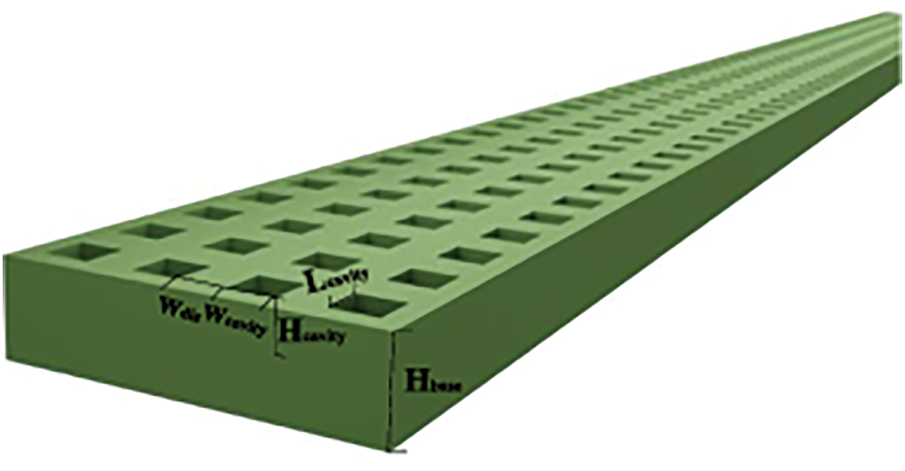
Figure 11: Schematic diagram of microchannel with artificial microcavity [66]
4.1.2 Adding Porous Materials Filled within Microchannels
Adding fins to microchannels can improve their thermal performance, but the resulting large pressure drop requires additional pump power, limiting their application scope. However, combining porous materials with fins—specifically filling microchannels with porous micro-fins—allows the coolant to flow into the porous fins. Under such conditions, a non-zero velocity occurs at the fluid-solid interface, known as the slip effect. Studies have shown that this porous design significantly reduces irreversible losses during heat transfer. Additionally, when porous structures such as porous fins are filled within microchannels, the working fluid flowing into the porous structure leads to interactions between the fluid and solid layers, redevelops the boundary layer, and enhances flow mixing—all factors conducive to improving heat transfer efficiency. Chen et al. [67] found that the permeability of porous fins induces fluid slip at the wall, similar to superhydrophobic surfaces, reducing frictional resistance and decreasing pressure drop by 19%. The porous structure also avoids flow separation and eddies caused by traditional solid fins, reducing local pressure losses. By arranging 75% porous fins on the outlet side of manifold microchannels, they achieved the best balance between heat transfer enhancement (19.8% reduction in thermal resistance) and pressure drop control (13% reduction), with the comprehensive performance factor increasing by 46.2%.
Wang et al. [68] conducted a numerical study on the heat transfer and hydraulic characteristics of microchannels with different porous fin shapes (circular fins, square fins, regular fins, and hierarchical honeycomb fins) (as shown in Fig. 12). They found that when using only solid fins, circular solid fins had the lowest pressure drop but the poorest heat dissipation capacity; when using porous fins, hierarchical honeycomb porous fins exhibited lower pressure drop and optimal heat dissipation effect, achieving the best comprehensive performance. Lori and Vafai [69] evaluated the effects of fins with different geometric shapes (including rectangular, elliptical, isosceles triangular, inverted triangular, and equilateral triangular) on microchannel walls (as shown in Fig. 13). Rectangular porous fins had the best heat transfer performance at low Reynolds numbers (Re) due to their largest surface area; elliptical fins showed superior comprehensive performance at high Re due to more uniform flow disturbance; forward-facing triangular fins had the lowest pressure drop due to minimal flow separation, but their heat transfer performance was lower due to smaller heat transfer area. Through permeation effects, shape optimization, and parameter adjustment, porous fins achieved an excellent balance between heat transfer enhancement (Nusselt number (Nu) increased by 2.5–4 times) and pressure drop reduction (Δp decreased by 81.7%).
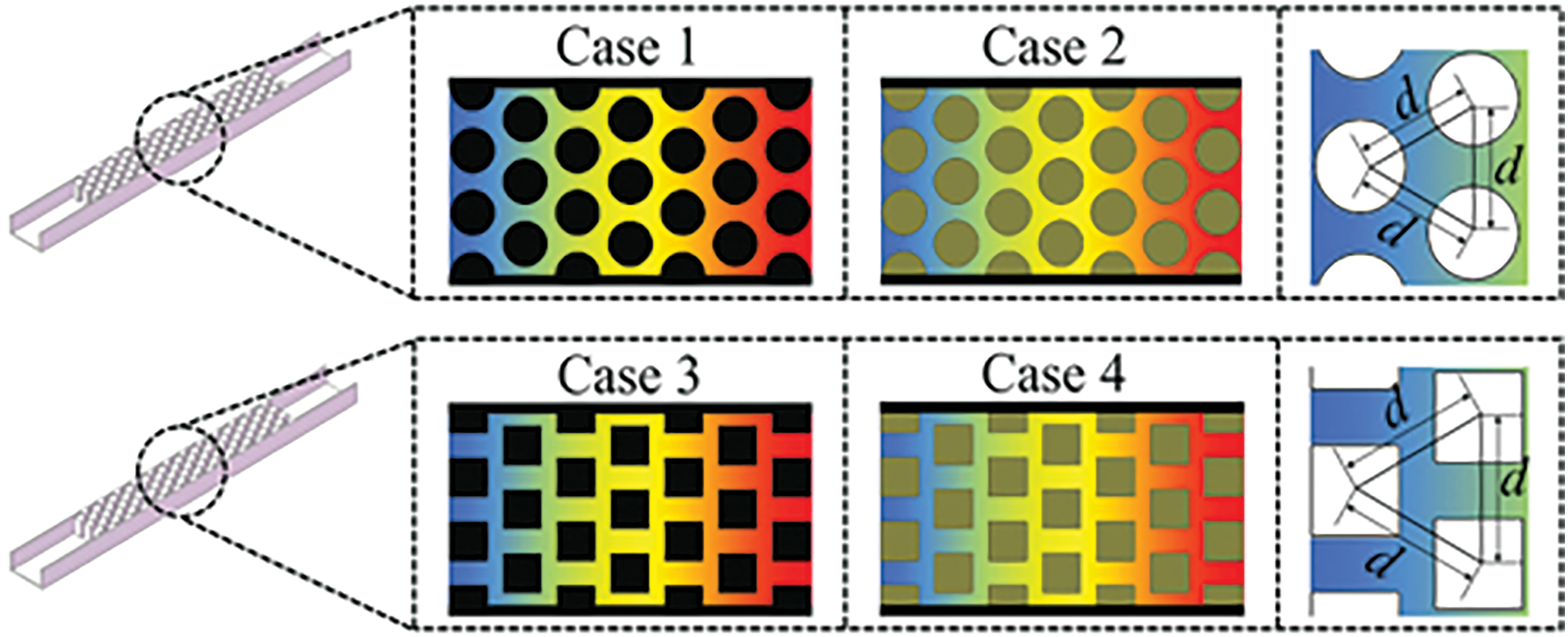
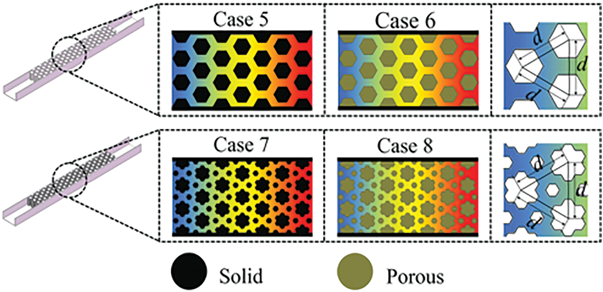
Figure 12: Microchannels with different porous fin shapes [68]
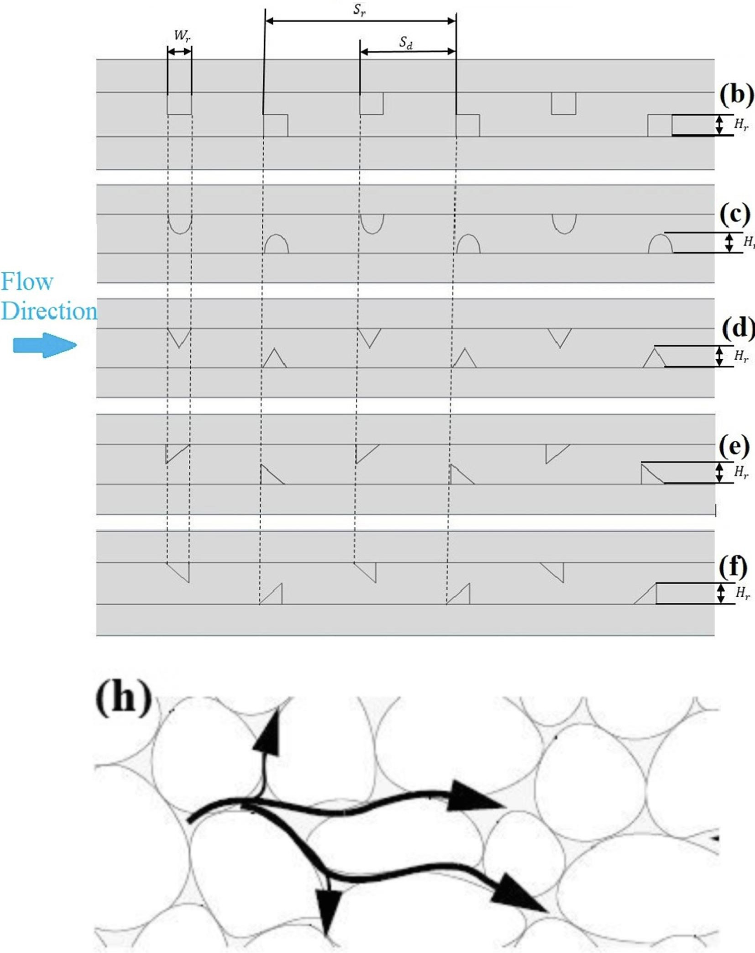
Figure 13: Finned microchannels with different geometric shapes (b–f) and porous finned microchannels (h) [69]
4.1.3 Adding Porous Microchannel Frameworks
Different from filling microchannels with porous fins, in the case where the microchannel framework itself is a porous structure, the porous fins form the channel walls. The direct presence of a porous structure in the walls creates a connectivity effect between the walls. Moreover, the porous fins in the microchannels cause the coolant to “slip” on the channel walls, resulting in a lower pressure drop compared to microchannels with solid porous matrix walls. In the optimized design of rectangular heat sinks, Chuan et al. [70] demonstrated that porous fins, through slip effects and permeation mechanisms, significantly reduce pressure drop (43.0%–47.9%) while only slightly increasing thermal resistance (approximately 5%).
Lu et al. [71] proposed a wavy porous micro-fin structure. The wavy microchannels can induce Dean vortices, enhance fluid mixing, disrupt the thermal boundary layer, and improve heat transfer efficiency. Additionally, the wavy design increases the equivalent channel length, prolonging the contact time between the fluid and the wall to enhance heat transfer. Through the synergistic effect of the permeation effect, slip effect, and wavy structure, the wavy porous fins significantly reduce pressure drop (31.4%–47.3%) while effectively decreasing thermal resistance (10.6%–17.1%).
Li et al. [72] designed a double-layer microchannel heat sink with porous fins in the upper layer and solid fins in the lower layer (as shown in Fig. 14). The upper-layer porous fins allow fluid permeation, expanding the heat transfer area and enhancing local convective heat transfer; the lower-layer solid fins (made of copper with high thermal conductivity) ensure efficient heat transfer from the base to the fluid, avoiding the deficiency of porous fins in thermal conductivity. The counter-current flow of fluids in the upper and lower layers significantly reduces the temperature gradient along the flow path and minimizes hotspots, with the maximum temperature difference (ΔTb) decreasing by 52.44%–58.04%. Through the synergistic design of lower-layer solid fins and upper-layer porous fins, the improved double-layer microchannel heat sink significantly reduces pressure drop (31.4%–47.3%) and effectively decreases thermal resistance (9.08%–10.91%).
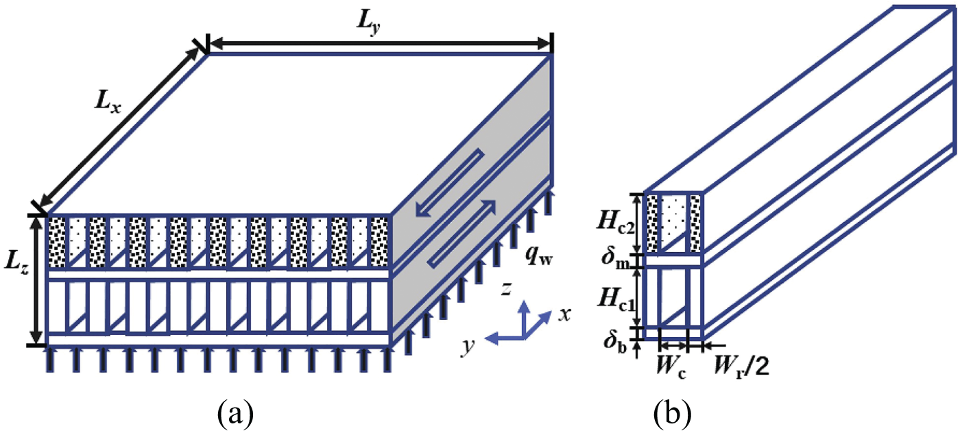
Figure 14: Schematics of double-layer microchannel heat sink with porous fins in the upper layer and solid fins in the lower layer [72]. (a) The improved design, (b) computational unit of the improved design
Wang et al. [73] optimized the previous design and proposed a double-layer microchannel heat sink with parallel symmetric wavy porous fins, as shown in Fig. 15. The wavy microchannels improve heat transfer by enhancing fluid mixing, while the double-layer structure optimizes temperature distribution through counter-current flow. Combining these two features with the permeation and slip effects of porous fins, the design significantly reduces pressure drop while maintaining high-efficiency heat transfer, achieving a triple optimization of reduced thermal resistance, decreased pressure drop, and improved temperature uniformity.
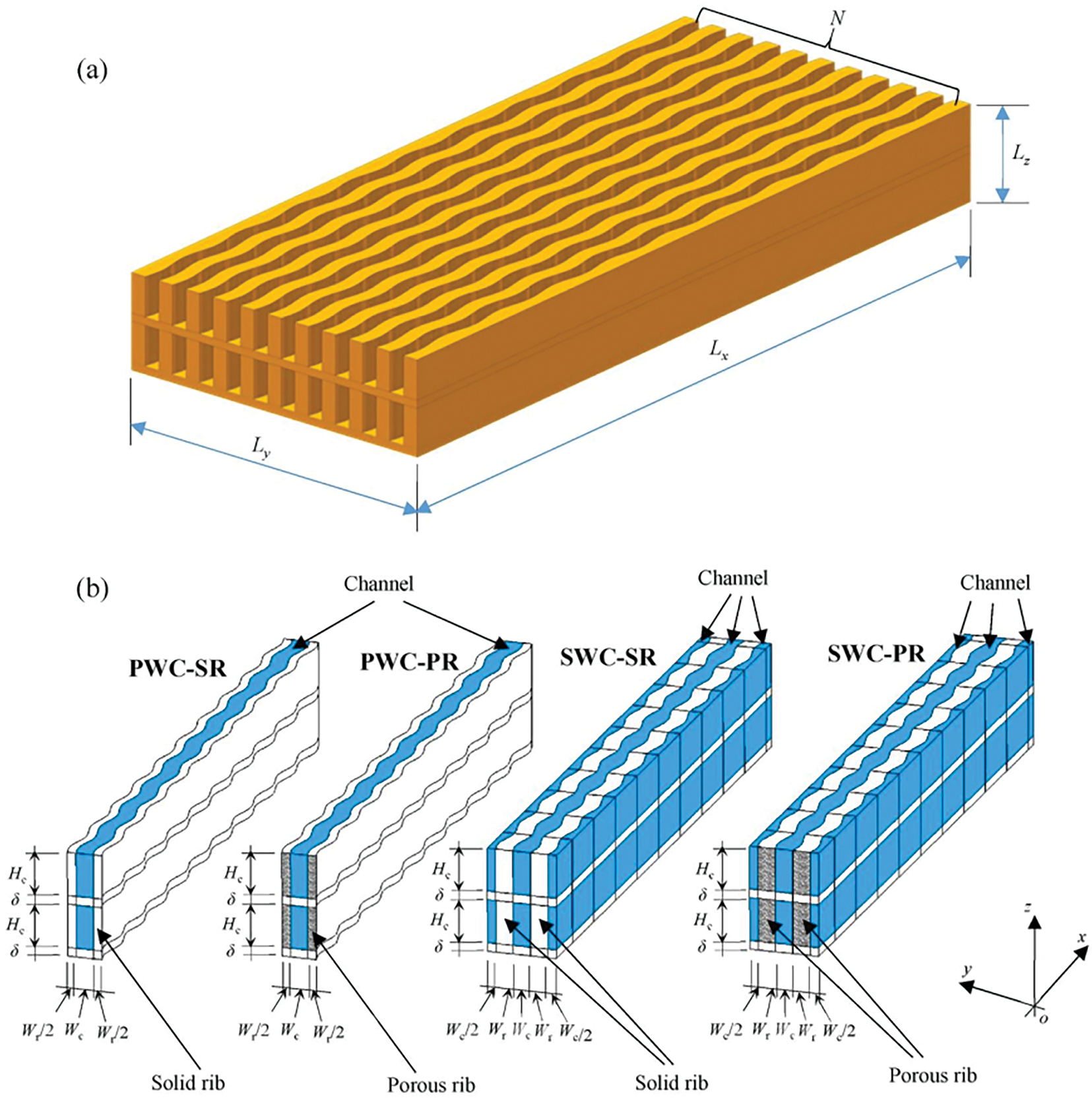
Figure 15: Schematics of double-layer microchannel heat sink with parallel symmetric wavy porous fins [73]. (a) Schematic diagrams of two-layered microchannel heat sink with wavy walls and (b) four designs. PWC-SR: the parallel configuration with solid ribs; PWC-PR: the parallel configuration with porous ribs; SWC-SR: the symmetric configuration with solid ribs; SWC-PR: the symmetric configuration with porous ribs
Compared with filling microchannels with porous materials, microchannels with a porous framework structure exhibit better heat transfer performance. They further enhance bubble nucleation and flow boiling heat transfer, strengthen the disruption of the wall boundary layer, and the adjacent channels in the microchannel induce lateral fluid flow, thereby enhancing heat transfer [64]. Therefore, considering all three types, microchannels with a porous framework structure offer the best heat dissipation performance. Moreover, designing the porous framework structure as a double layer with arrayed porous fins achieves the optimal overall performance.
Porous materials have the advantages of reducing pressure drop and enhancing heat transfer. However, since they are often manufactured using sintering or 3D printing technologies, and the geometric accuracy and surface finish of the machined parts are poor, the pressure drop and pump power may increase. Therefore, there are still challenges in the manufacturing and application of porous materials. At present, some researchers [74] have studied high-precision 3D printing technologies such as selective laser melting (SLM), which may be used for the manufacturing of porous materials in the future. Xu et al. [75] integrated the 3D printed porous material into a 32-pair thermoelectric coolers (TEC), which was able to produce a temperature difference of up to 50°C between the hot and cold ends in the air, with performance comparable to the most advanced thermoelectric coolers. It is verified that porous materials have good performance and potential in practical thermoelectric refrigeration applications.
4.2 Optimization of the Flow Distribution in Microchannels
Pressure drop oscillations caused by uneven two-phase flow distribution in parallel microchannels are also a key issue in optimizing two-phase flow heat dissipation systems. When two-phase flow passes through flow distribution devices, uneven distribution inevitably occurs. This uneven distribution involves not only unequal flow rate distribution among branches but also unequal two-phase quality in each branch. The uneven distribution of two-phase flow deteriorates the thermodynamic and hydraulic performance of downstream equipment, failing to ensure the outlet superheat and the working fluid’s pressure drop. As shown in Fig. 16, such uneven distribution of the working fluid leads to reduced heat transfer performance and fluctuations in pressure drop, not only resulting in inefficient utilization of the working fluid but also potentially causing “dry-out” in some branches [76,77].
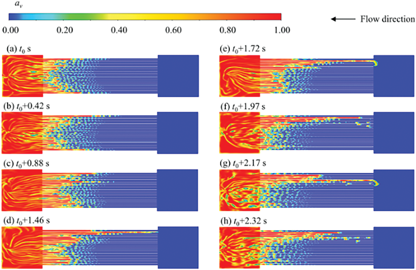
Figure 16: Two-phase flow fluctuations in parallel tube radiators [77]. (a)
To address the flow distribution issue in parallel microchannels, many scholars have proposed new types of flow distributors. Zhao et al. [78] started from the perspective of two-phase flow patterns, achieving uniform distribution by rectifying the two-phase flow into annular flow. When the outlet pipes are symmetrically arranged relative to the inlet pipe, the flow-pattern-symmetric refrigerant can be evenly distributed to each outlet pipe. In vertical installation, this distributor reduced the distribution non-uniformity of R141b by 24% to 47%. Liang et al. [79] enhanced the rectification effect using swirl vanes: due to the liquid density being much greater than the gas density, the liquid is dragged to the inner surface of the pipe by centrifugal force, rectifying the asymmetric flow pattern into annular flow. Additionally, this distributor incorporates nozzles at the outlets based on the rectification function, ensuring the same pressure drop at each outlet. Testing with a two-phase flow of water and air showed good distribution performance. Sun et al. [80] proposed a rectifying nozzle-type critical distributor and tested it with R22. As shown in Fig. 17, the distributor consists of three main parts: under the action of swirl vanes, the two-phase flow forms annular flow through centrifugation, eliminating the effects of upstream unstable flow and gravity; a Venturi tube further rectifies the annular flow, removing the influence of centrifugal force; finally, the two-phase flow is accelerated through a sonic nozzle to form critical flow, dampening pressure drop fluctuations caused by downstream uneven heat transfer.
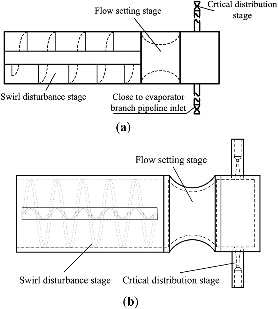
Figure 17: Nozzle-type critical distributor [80]. (a) First-generation rectifier nozzle-type critical distributor, (b) second-generation rectifier nozzle-type critical distributor
In addition to splitting the inlet two-phase working fluid, some researchers have proposed rectifying the outlet two-phase working fluid. As shown in Fig. 18, Xiong et al. [81] enhanced heat exchanger performance by adding a gas-liquid separator and bypass valve, which separate the outlet two-phase refrigerant and enable secondary evaporation before it returns to the compressor. This effectively cuts the evaporator’s pressure drop. Simulations show that when the evaporator model’s heat transfer capacity ranges from 5.5 to 13.5 kW, the optimized vapor-bypassed circuit can reduce the evaporator’s pressure drop by 23.7–98.8 kPa. Moreover, the evaporator’s performance improvement is more pronounced as the load increases.
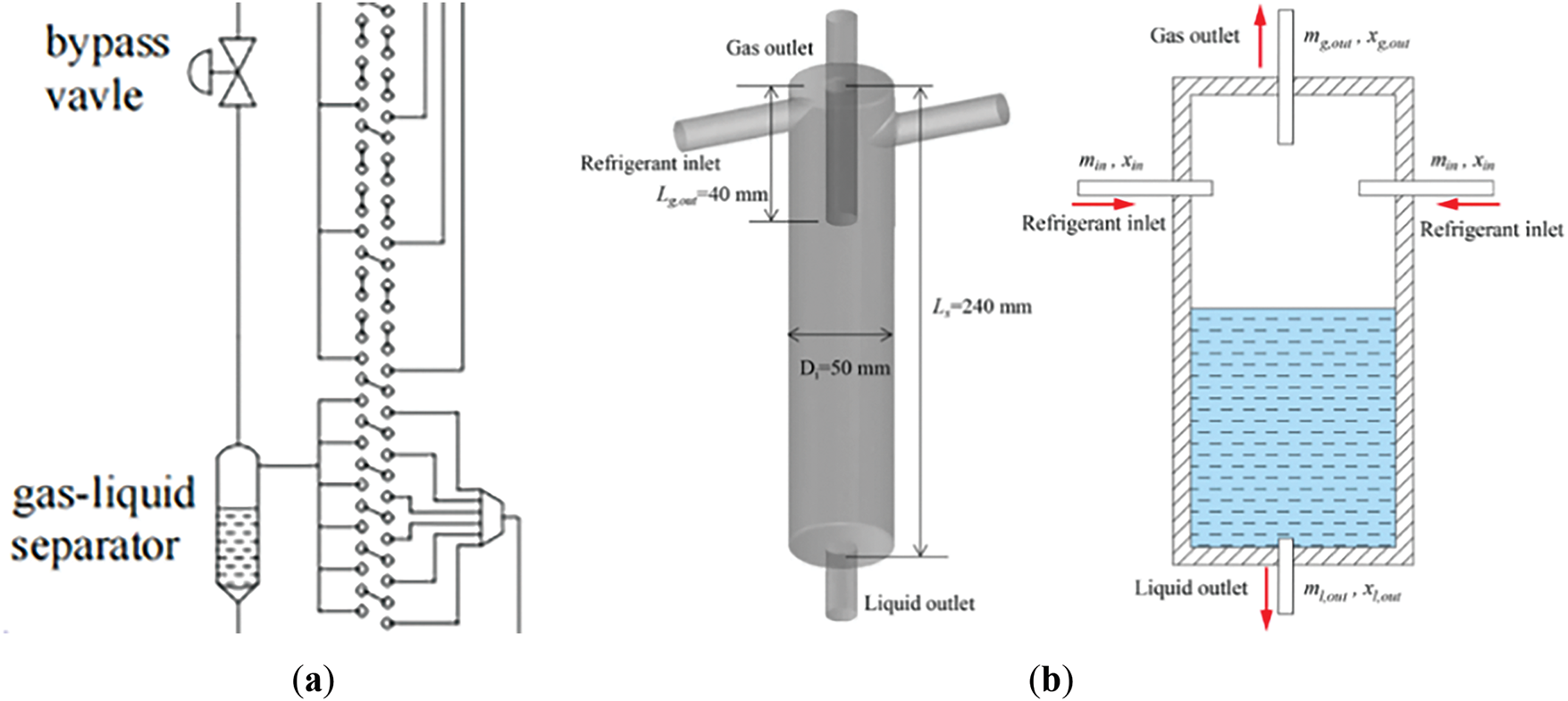
Figure 18: Optimization of the heat exchanger [81]. (a) Bypass valve, and (b) structure of gas-liquid separator
By optimizing microchannel structures and addressing uneven flow distribution issues, it is possible to effectively balance pressure drop and heat transfer performance. Porous structures and specially designed fins can enhance heat transfer while reducing pressure drop, and improved flow distributors can achieve more uniform fluid distribution. These optimization measures have demonstrated good pressure drop reduction and heat transfer effects in various application scenarios, providing effective technical approaches for the thermal management of high-power-density devices. Future research should further explore the relationship between microchannel structures and fluid flow characteristics, and develop more efficient optimization strategies to meet the growing heat dissipation demands.
In the optimization of two-phase flow heat dissipation systems, there is often a need to improve heat transfer characteristics without causing a significant increase in pressure drop. Researchers have proposed various strategies from micro to system levels. Microchannel structure optimization mainly includes adding porous structures to the microchannel surface, filling the microchannel interior with porous materials, and replacing the microchannel framework with a porous structure. Among these three approaches, the porous microchannel framework exhibits the best comprehensive performance. Additionally, pressure drop oscillations caused by uneven two-phase flow distribution in parallel microchannels are a key issue in optimizing two-phase flow heat dissipation systems. Improving the design of flow distributors effectively addresses the problem of uneven two-phase flow distribution, which is of great significance for enhancing microchannel flow, reducing pressure drop fluctuations, and improving overall heat transfer performance.
This paper comprehensively reviews the experimental studies on the pressure drop characteristics and prediction models of two-phase flow in microchannels, discusses the technologies for reducing pressure drop and suppressing pressure drop instability, and draws the following conclusions.
(a) Scholars have widely studied the pressure drop of conventional fluids in microchannels, using experiments and simulations. Key factors like fluid properties, channel structure, operating conditions, and flow patterns interact complexly across multiple physical fields. Some progress in multi-field coupling research exists, but the understanding of strong coupling effect induced pressure drop is still poor. Also, research on pressure drop under extreme physical properties is scarce.
(b) There are various models for two-phase flow pressure drop prediction. The homogeneous flow model simplifies calculations by treating two-phase flow as a mixed fluid. Classical separated flow models account for interphase interactions but are for macrochannels. Researchers have enhanced them by considering micro-scale effects and modified models for specific fluids and conditions improve accuracy. Flow-pattern-based models offer better precision but face issues due to flow pattern classification problems. Machine learning, a recent hot topic, overcomes traditional model limitations, yet has challenges like data noise and lack of physical explanations. Future research should refine model physics, consider multi-physical field coupling, and develop better data handling methods for more accurate and applicable models.
(c) In two-phase flow heat dissipation system optimization, researchers aim to boost heat transfer without large pressure drop increases. They’ve put forward strategies from micro to system levels. Microchannel structure optimization involves adding surface porous structures, filling interior with porous materials, or using a porous framework, with the latter having the best overall performance. Also, uneven two-phase flow in parallel microchannels causes pressure drop issues, and better flow distributor design can solve this, enhancing flow, reducing fluctuations, and improving heat transfer.
(d) In summary, future research can focus on the following directions: (i) Further improve the physical basis of existing two-phase flow pressure drop prediction models and better consider the coupling effects of multiple physical fields, such as hydrodynamics, thermodynamics and heat transfer. (ii) Strengthen research on pressure drops in two-phase flows under extreme physical conditions, such as ultra-low surface tension, ultra-high viscosity, and dynamic changes in physical parameters with temperature or pressure. (iii) Conduct in-depth study of the relationship between microchannel structure and fluid flow characteristics, and develop more innovative microchannel structure optimization strategies. At the same time, it combines advanced manufacturing technologies, such as 3D printing and micro-nano machining, to achieve efficient manufacturing and precise control of complex microchannel structures.
Acknowledgement: Not applicable.
Funding Statement: This research was supported by the Beijing Municipal Science & Technology Commission (Z231100006123010).
Author Contributions: The authors confirm contribution to the paper as follows: study conception and design: Zongyu Jie and Chao Dang; data collection: Zongyu Jie; analysis and interpretation of results: Zongyu Jie and Qingliang Meng; draft manuscript preparation: Zongyu Jie. All authors reviewed the results and approved the final version of the manuscript.
Availability of Data and Materials: Data available on request from the authors.
Ethics Approval: Not applicable.
Conflicts of Interest: The authors declare no conflicts of interest to report regarding the present study.
Nomenclature
| Bond number | |
| Two-phasemultiplierparameter | |
| Convection number | |
| Correction factor for interfacial friction factor | |
| D | Curvature diameter |
| d | Diameter |
| Entrainment rate | |
| Friction factor | |
| j | Superficial velocity |
| Mass flux | |
| Channel length | |
| m | Mass flow rate |
| P | Pressure |
| q | Heat flux |
| Re | Reynolds number |
| Greek Symbols | |
| Two-phase friction multipliers | |
| Dynamic viscous | |
| Density | |
| Surface tension | |
| Void fraction | |
| Shear stress | |
| Deposition mass transfer rate per unit length | |
| Evaporation mass transfer rate per unit length | |
| Subscripts | |
| Actuated | |
| Average | |
| Contraction | |
| Channel | |
| Dryout completion | |
| Dryout inception | |
References
1. Anderson TM, Mudawar I. Microelectronic cooling by enhanced pool boiling of a dielectric fluorocarbon liquid. J Heat Transf. 1989;111(3):752–9. doi:10.1115/1.3250747. [Google Scholar] [CrossRef]
2. Naqiuddin NH, Saw LH, Yew MC, Yusof F, Ng TC, Yew MK. Overview of micro-channel design for high heat flux application. Renew Sustain Energy Rev. 2018;82:901–14. doi:10.1016/j.rser.2017.09.110. [Google Scholar] [CrossRef]
3. Mudawar I. Two-phase microchannel heat sinks: theory, applications, and limitations. J Electron Packag. 2011;133(4):041002. doi:10.1115/1.4005300. [Google Scholar] [CrossRef]
4. Tuckerman DB, Pease RFW. High-performance heat sinking for VLSI. IEEE Electron Device Lett. 1981;2(5):126–9. doi:10.1109/EDL.1981.25367. [Google Scholar] [CrossRef]
5. Kim SM, Mudawar I. Thermal design and operational limits of two-phase micro-channel heat sinks. Int J Heat Mass Transf. 2017;106(Pt. II):861–76. doi:10.1016/j.ijheatmasstransfer.2016.10.020. [Google Scholar] [CrossRef]
6. Bhandari P, Rawat KS, Prajapati YK, Padalia D, Ranakoti L, Singh T. Design modifications in micro pin fin configuration of microchannel heat sink for single phase liquid flow: a review. J Energy Storage. 2023;66(2):107548. doi:10.1016/j.est.2023.107548. [Google Scholar] [CrossRef]
7. Ma X, Hu C, Ji X, Yang X, Xu N, Zhang Y, et al. Flow boiling frictional pressure drop inside micro/mini-channels: a new general model and experimental investigation. Appl Therm Eng. 2024;247(2):123111. doi:10.1016/j.applthermaleng.2024.123111. [Google Scholar] [CrossRef]
8. Fang X, Qiu G, Chen J, Liu K, Li Q, Cai W. A new frictional pressure drop correlation based on flow patterns for hydrocarbon refrigerants condensation flow. Int J Refrig. 2025;170(9–10):214–23. doi:10.1016/j.ijrefrig.2024.11.024. [Google Scholar] [CrossRef]
9. Mudawar I, Darges SJ, Devahdhanush VS, Hasan MM, Nahra HK, Balasubramaniam R, et al. Pressure drop characteristics and prediction techniques (models/correlations and artificial neural networks) for microgravity flow boiling onboard the International Space Station. Int J Heat Mass Transf. 2025;240(21):126593. doi:10.1016/j.ijheatmasstransfer.2024.126593. [Google Scholar] [CrossRef]
10. Pamitran AS, Choi KI, Oh JT, Hrnjak P. Characteristics of two-phase flow pattern transitions and pressure drop of five refrigerants in horizontal circular small tubes. Int J Refrig. 2010;33(3):578–88. doi:10.1016/j.ijrefrig.2009.12.009. [Google Scholar] [CrossRef]
11. AL-Dogail AS, Gajbhiye RN. Effects of density, viscosity and surface tension on flow regimes and pressure drop of two-phase flow in horizontal pipes. J Petrol Sci Eng. 2021;205(2):108719. doi:10.1016/j.petrol.2021.108719. [Google Scholar] [CrossRef]
12. Dewangan SK, Shrivastava SK, Haldar R, Yadav A, Giri V. Effect of density and viscosity on flow characteristics of water: a review. Int J Res Publ Rev. 2023;4(6):1982–5. [Google Scholar]
13. Wang CC, Chiang SK, Chang YJ, Chung TW. Two-phase flow resistance of refrigerants R-22, R-410A and R-407C in small diameter tubes. Chem Eng Res Des. 2001;79(5):553–60. doi:10.1205/02638760152424325. [Google Scholar] [CrossRef]
14. Ehsan MM, Guan Z, Klimenko AY. A comprehensive review on heat transfer and pressure drop characteristics and correlations with supercritical CO2 under heating and cooling applications. Renew Sustain Energy Rev. 2018;92(1):658–75. doi:10.1016/j.rser.2018.04.106. [Google Scholar] [CrossRef]
15. Xu GP, Tso CP, Tou KW. Hydrodynamics of two-phase flow in vertical up and down-flow across a horizontal tube bundle. Int J Multiph Flow. 1998;24(8):1317–42. doi:10.1016/S0301-9322(98)00035-4. [Google Scholar] [CrossRef]
16. Fazelnia H, Azarhazin S, Sajadi B, Ali Akhavan Behabadi M, Zakeralhoseini S, Rafieinejad MV. Two-phase R1234yf flow inside horizontal smooth circular tubes: heat transfer, pressure drop, and flow pattern. Int J Multiph Flow. 2021;140(29):103668. doi:10.1016/j.ijmultiphaseflow.2021.103668. [Google Scholar] [CrossRef]
17. Mattiuzzo N, Azzolin M, Berto A, Bortolin S, Del Col D. Condensation heat transfer and pressure drop of R1234yf/HFC mixtures inside small diameter channels. Int J Therm Sci. 2023;189:108258. doi:10.1016/j.ijthermalsci.2023.108258. [Google Scholar] [CrossRef]
18. Song JY, Kim DH, Song CH, Kang YT. Comparisons of two-phase condensation and single-phase heat transfer and frictional pressure drop characteristics and energy-saving performance analysis of R-32 and R-410A in plate heat exchanger. Int J Heat Mass Transf. 2024;231(517):125813. doi:10.1016/j.ijheatmasstransfer.2024.125813. [Google Scholar] [CrossRef]
19. Del Col D, Azzolin M, Bisetto A, Bortolin S. Frictional pressure drop during two-phase flow of pure fluids and mixtures in small diameter channels. Int J Chem React Eng. 2015;13(4):493–502. doi:10.1515/ijcre-2014-0180. [Google Scholar] [CrossRef]
20. Yang Z, Gong M, Chen G, Zou X, Shen J. Two-phase flow patterns, heat transfer and pressure drop characteristics of R600a during flow boiling inside a horizontal tube. Appl Therm Eng. 2017;120:654–71. doi:10.1016/j.applthermaleng.2017.03.124. [Google Scholar] [CrossRef]
21. Wang Y, Zheng W, Guo J, Tian Z, Wang F, Jiang Y, et al. Experimental investigation on the frictional pressure drop of two-phase fluids in the shell side of LNG spiral-wound heat exchangers. Therm Sci Eng Prog. 2024;47(9):102375. doi:10.1016/j.tsep.2023.102375. [Google Scholar] [CrossRef]
22. Tibiriçá CB, Ribatski G. Two-phase frictional pressure drop and flow boiling heat transfer for R245fa in a 2.32-mm tube. Heat Transf Eng. 2011;32(13–14):1139–49. doi:10.1080/01457632.2011.562725. [Google Scholar] [CrossRef]
23. Xu Y, Liu Y, Lu Z, Wang H, Sun D, Yang G. The preparation and role of Li2ZrO3 surface coating LiNi0.5Co0.2Mn0.3O2 as cathode for lithium-ion batteries. Appl Surf Sci. 2016;361:150–6. doi:10.1016/j.apsusc.2015.11.156. [Google Scholar] [CrossRef]
24. Yu J, Ma H, Jiang Y. A numerical study of heat transfer and pressure drop of hydrocarbon mixture refrigerant during boiling in vertical rectangular minichannel. Appl Therm Eng. 2017;112:1343–52. doi:10.1016/j.applthermaleng.2016.10.151. [Google Scholar] [CrossRef]
25. Li C, Fang X. Boiling heat transfer and pressure drop characteristics of R245fa in microchannel. J Eng Thermophys. 2024;45(12):3750–5. (In Chinese). [Google Scholar]
26. Xie YC, Zhuang XR, Yue SJ, Li X, Yu P, Lu C. Experimental study on flow boiling of HFE-7100 in rectangular parallel microchannel. Acta Phys Sin. 2024;73(5):054401. (In Chinese). doi:10.7498/aps.73.20231415. [Google Scholar] [CrossRef]
27. Revellin R, Thome JR. Adiabatic two-phase frictional pressure drops in microchannels. Exp Therm Fluid Sci. 2007;31(7):673–85. doi:10.1016/j.expthermflusci.2006.07.001. [Google Scholar] [CrossRef]
28. Kim SM, Mudawar I. Analytical heat diffusion models for different micro-channel heat sink cross-sectional geometries. Int J Heat Mass Transf. 2010;53(19–20):4002–16. doi:10.1016/j.ijheatmasstransfer.2010.05.019. [Google Scholar] [CrossRef]
29. Tutwiler SA, Shaver DR, Carasik LB. Influence of cross-sectional aspect ratio and Prandtl numbers on pressure drop and heat transfer characteristics in twisted elliptical tube bundles. Int J Heat Fluid Flow. 2024;109(1):109494. doi:10.1016/j.ijheatfluidflow.2024.109494. [Google Scholar] [CrossRef]
30. Zhang J, An J, Lei L, Wang X, Xin G, Wu Z. Numerical investigation of heat transfer and pressure drop characteristics of flow boiling in manifold microchannels with a simple multiphase model. Int J Heat Mass Transf. 2023;211(5):124197. doi:10.1016/j.ijheatmasstransfer.2023.124197. [Google Scholar] [CrossRef]
31. Wang Y, Ma W, Wang S. Numerical simulation on pressure drop characteristics of gas-liquid two-phase flow through a T-shaped and right-angle elbow coupling pipe. J Yan’an Univ Nat Sci Ed. 2023;42(4):16–21. (In Chinese). doi:10.13876/J.cnki.ydnse.230089. [Google Scholar] [CrossRef]
32. Wang Z, He Y, Li M, Qiu M, Huang C, Liu Y. Numerical simulation and flow pattern evolution of gas-liquid two-phase flow passing through a 90° pipe bend based on CFD. J Shanghai Jiaotong Univ. 2022;9:1159–67. (In Chinese). doi:10.16183/j.cnki.jsjtu.2021.185. [Google Scholar] [CrossRef]
33. Muzaffar A, Abbas A, Cremaschi L, Ayub Z, Cheema TA. Two phase frictional pressure drop in horizontal and vertical return bends with Ammonia. Int J Refrig. 2025;170(1):255–72. doi:10.1016/j.ijrefrig.2024.11.021. [Google Scholar] [CrossRef]
34. Gao Y, Wang Z, Li Y, Ma E, Yu H. Flow boiling of liquid nitrogen in a horizontal macro-tube at low pressure: part I—flow pattern, two-phase flow instability, and pressure drop. Int J Heat Fluid Flow. 2024;107(2):109335. doi:10.1016/j.ijheatfluidflow.2024.109335. [Google Scholar] [CrossRef]
35. McAdams WH, Kennel WE, Minden CS, Carl R, Picornell PM, Dew JE. Heat transfer at high rates to water with surface boiling. Ind Eng Chem. 1949;41(9):1945–53. doi:10.1021/ie50477a027. [Google Scholar] [CrossRef]
36. Akers WW, Deans HA, Crosser OK. Condensing heat transfer within horizontal tubes. Chem Eng Process. 1959;55:171–6. [Google Scholar]
37. Cicchitti A, Lombardi C, Silvestri M, Soldaini G, Zavattarelli R. Two-phase cooling experiments: pressure drop heat transfer and burnout measurements. Milan, Italy: Centro Informazioni Studi Esperienze; 1959 [cited 2025 Jan 1]. Available from: https://www.osti.gov/biblio/4181977. [Google Scholar]
38. Dukler AE, Wicks III MIII, Cleveland RG. Frictional pressure drop in two-phase flow: B. An approach through similarity analysis. AlChE J. 1964;10(1):44–51. doi:10.1002/aic.690100118. [Google Scholar] [CrossRef]
39. Beattie DRH, Whalley PB. A simple two-phase frictional pressure drop calculation method. Int J Multiph Flow. 1982;8(1):83–7. doi:10.1016/0301-9322(82)90009-X. [Google Scholar] [CrossRef]
40. Lin S, Kwok CCK, Li RY, Chen ZH, Chen ZY. Local frictional pressure drop during vaporization of R-12 through capillary tubes. Int J Multiph Flow. 1991;17(1):95–102. doi:10.1016/0301-9322(91)90072-B. [Google Scholar] [CrossRef]
41. Awad MM, Muzychka YS. Effective property models for homogeneous two-phase flows. Exp Therm Fluid Sci. 2008;33(1):106–13. doi:10.1016/j.expthermflusci.2008.07.006. [Google Scholar] [CrossRef]
42. Shannak BA. Frictional pressure drop of gas liquid two-phase flow in pipes. Nucl Eng Des. 2008;238(12):3277–84. doi:10.1016/j.nucengdes.2008.08.015. [Google Scholar] [CrossRef]
43. Maher D, Hana A, Habib S. New correlations for two phase flow pressure drop in homogeneous flows model. Therm Eng. 2020;67(2):92–105. doi:10.1134/s0040601520020032. [Google Scholar] [CrossRef]
44. Lockhart WR. Proposed correlation of data for isothermal two-phase, two-component flow in pipes. Chem Eng Prog. 1949;45(1):39–48. [Google Scholar]
45. Chisholm D. A theoretical basis for the Lockhart-Martinelli correlation for two-phase flow. Int J Heat Mass Transf. 1967;10(12):1767–78. doi:10.1016/0017-9310(67)90047-6. [Google Scholar] [CrossRef]
46. Mishima K, Hibiki T. Some characteristics of air-water two-phase flow in small diameter vertical tubes. Int J Multiph Flow. 1996;22(4):703–12. doi:10.1016/0301-9322(96)00010-9. [Google Scholar] [CrossRef]
47. Lee HJ, Lee SY. Pressure drop correlations for two-phase flow within horizontal rectangular channels with small heights. Int J Multiph Flow. 2001;27(5):783–96. doi:10.1016/S0301-9322(00)00050-1. [Google Scholar] [CrossRef]
48. Lee J, Mudawar I. Two-phase flow in high-heat-flux micro-channel heat sink for refrigeration cooling applications: part II—heat transfer characteristics. Int J Heat Mass Transf. 2005;48(5):941–55. doi:10.1016/j.ijheatmasstransfer.2004.09.019. [Google Scholar] [CrossRef]
49. Hwang YW, Kim MS. The pressure drop in microtubes and the correlation development. Int J Heat Mass Transf. 2006;49(11–12):1804–12. doi:10.1016/j.ijheatmasstransfer.2005.10.040. [Google Scholar] [CrossRef]
50. Li W, Wu Z. A general correlation for adiabatic two-phase pressure drop in micro/mini-channels. Int J Heat Mass Transf. 2010;53(13–14):2732–9. doi:10.1016/j.ijheatmasstransfer.2010.02.029. [Google Scholar] [CrossRef]
51. Müller-Steinhagen H, Heck K. A simple friction pressure drop correlation for two-phase flow in pipes. Chem Eng Process Process Intensif. 1986;20(6):297–308. doi:10.1016/0255-2701(86)80008-3. [Google Scholar] [CrossRef]
52. Tao X, Ferreira CAI. NH3 condensation in a plate heat exchanger: flow pattern based models of heat transfer and frictional pressure drop. Int J Heat Mass Transf. 2020;154(25):119774. doi:10.1016/j.ijheatmasstransfer.2020.119774. [Google Scholar] [CrossRef]
53. Sun R, Song G, Zhang D, Su GH, Kulacki FA, Tian W. Flow boiling pressure drop characteristics in rectangular channels under uniform and non-uniform heating. Int J Heat Mass Transf. 2020;157(8):119811. doi:10.1016/j.ijheatmasstransfer.2020.119811. [Google Scholar] [CrossRef]
54. Hao B, Zhang C, Cheng L, Xu J, Wang Q. Experimental investigation on the pressure drop characteristics of subcritical and supercritical CO2 heated in a horizontal tube. Int J Heat Mass Transf. 2023;201(2):123650. doi:10.1016/j.ijheatmasstransfer.2022.123650. [Google Scholar] [CrossRef]
55. Moreno Quibén J, Thome JR. Flow pattern based two-phase frictional pressure drop model for horizontal tubes, Part II: new phenomenological model. Int J Heat Fluid Flow. 2007;28(5):1060–72. doi:10.1016/j.ijheatfluidflow.2007.01.004. [Google Scholar] [CrossRef]
56. Harirchian T, Garimella SV. Flow regime-based modeling of heat transfer and pressure drop in microchannel flow boiling. Int J Heat Mass Transf. 2012;55(4):1246–60. doi:10.1016/j.ijheatmasstransfer.2011.09.024. [Google Scholar] [CrossRef]
57. Hughes MT, Garimella S. A mechanistic model for acoustically enhanced condensation heat transfer and pressure drop. Int J Heat Mass Transf. 2023;216(4):124588. doi:10.1016/j.ijheatmasstransfer.2023.124588. [Google Scholar] [CrossRef]
58. Tian Z, Zheng W, Sun X, Wang L, Jiang Y, Mi X. Research on prediction model of two-phase flow and friction pressure drop in spiral pipe based on flow regimes. Therm Sci Eng Prog. 2024;56(8):103018. doi:10.1016/j.tsep.2024.103018. [Google Scholar] [CrossRef]
59. Qiu Y, Garg D, Kim SM, Mudawar I, Kharangate CR. Machine learning algorithms to predict flow boiling pressure drop in mini/micro-channels based on universal consolidated data. Int J Heat Mass Transf. 2021;178(64):121607. doi:10.1016/j.ijheatmasstransfer.2021.121607. [Google Scholar] [CrossRef]
60. Khosravi A, Pabon JJG, Koury RNN, Machado L. Using machine learning algorithms to predict the pressure drop during evaporation of R407C. Appl Therm Eng. 2018;133(16):361–70. doi:10.1016/j.applthermaleng.2018.01.084. [Google Scholar] [CrossRef]
61. Nie F, Yan S, Wang H, Zhao C, Zhao Y, Gong M. A universal correlation for predicting two-phase frictional pressure drop in horizontal tubes based on machine learning. Int J Multiph Flow. 2023;160:104377. doi:10.1016/j.ijmultiphaseflow.2022.104377. [Google Scholar] [CrossRef]
62. Yaqub MW, Chen X. Interpretable machine learning for three-phase flow pressure drop prediction: a comparative study with CFD and empirical models. Chem Eng Sci. 2025;310(11):121542. doi:10.1016/j.ces.2025.121542. [Google Scholar] [CrossRef]
63. Zhai C, Sui Y, Wu W. Machine learning-assisted correlations of heat/mass transfer and pressure drop of microchannel membrane-based desorber/absorber for compact absorption cycles. Int J Heat Mass Transf. 2023;214(11):124431. doi:10.1016/j.ijheatmasstransfer.2023.124431. [Google Scholar] [CrossRef]
64. Zhou X, Zhang L. Research status of microchannel heat dissipation technology based on porous structure. J Refrig. 2025;46(2):17–27. (In Chinese). [Google Scholar]
65. Aravinthan M, Sarkar S, Dhar P, Das SK, Balakrishnan AR. Flow boiling heat transfer characteristics in minitubes with and without hydrophobicity coating. Heat Transf Eng. 2020;41(3):288–301. doi:10.1080/01457632.2018.1528066. [Google Scholar] [CrossRef]
66. Lin Y, Luo Y, Li W, Minkowycz WJ. Enhancement of flow boiling heat transfer in microchannel using micro-fin and micro-cavity surfaces. Int J Heat Mass Transf. 2021;179(3):121739. doi:10.1016/j.ijheatmasstransfer.2021.121739. [Google Scholar] [CrossRef]
67. Chen C, Li F, Wang X, Zhang J, Xin G. Improvement of flow and heat transfer performance of manifold microchannel with porous fins. Appl Therm Eng. 2022;206(3):118129. doi:10.1016/j.applthermaleng.2022.118129. [Google Scholar] [CrossRef]
68. Wang M, Zhang W, Xin G, Li F, Pu JH, Du M. Improved thermal–hydraulic performance of a microchannel with hierarchical honeycomb porous ribs. Can J Chem Eng. 2023;101(2):1083–94. doi:10.1002/cjce.24378. [Google Scholar] [CrossRef]
69. Lori MS, Vafai K. Heat transfer and fluid flow analysis of microchannel heat sinks with periodic vertical porous ribs. Appl Therm Eng. 2022;205(4):118059. doi:10.1016/j.applthermaleng.2022.118059. [Google Scholar] [CrossRef]
70. Chuan L, Wang XD, Wang TH, Yan WM. Fluid flow and heat transfer in microchannel heat sink based on porous fin design concept. Int Commun Heat Mass Transf. 2015;65:52–7. doi:10.1016/j.icheatmasstransfer.2015.04.005. [Google Scholar] [CrossRef]
71. Lu G, Zhao J, Lin L, Wang XD, Yan WM. A new scheme for reducing pressure drop and thermal resistance simultaneously in microchannel heat sinks with wavy porous fins. Int J Heat Mass Transf. 2017;111:1071–8. doi:10.1016/j.ijheatmasstransfer.2017.04.086. [Google Scholar] [CrossRef]
72. Li XY, Wang SL, Wang XD, Wang TH. Selected porous-ribs design for performance improvement in double-layered microchannel heat sinks. Int J Therm Sci. 2019;137:616–26. doi:10.1016/j.ijthermalsci.2018.12.029. [Google Scholar] [CrossRef]
73. Wang SL, An D, Yang YR, Zheng SF, Wang XD, Lee DJ. Heat transfer and flow characteristics in symmetric and parallel wavy microchannel heat sinks with porous ribs. Int J Therm Sci. 2023;185:108080. doi:10.1016/j.ijthermalsci.2022.108080. [Google Scholar] [CrossRef]
74. Peng J, Li J, Liu B, Wang J, Chen H, Feng H, et al. Formation process and mechanical properties in selective laser melted multi-principal-element alloys. J Mater Sci Technol. 2023;133:12–22. doi:10.1016/j.jmst.2022.06.017. [Google Scholar] [CrossRef]
75. Xu S, Horta S, Lawal A, Maji K, Lorion M, Ibáñez M. Interfacial bonding enhances thermoelectric cooling in 3D-printed materials. Science. 2025;387(6736):845–50. doi:10.1126/science.ads0426. [Google Scholar] [PubMed] [CrossRef]
76. He K, Wang S, Huang J. The effect of flow pattern on split of two-phase flow through a micro-T-junction. Int J Heat Mass Transf. 2011;54(15–16):3587–93. doi:10.1016/j.ijheatmasstransfer.2011.03.028. [Google Scholar] [CrossRef]
77. Huang Y, Chen K, Tang X, Fang Y. Two-phase flow oscillation and distribution in parallel channels during R1233zd(E) subcooled flow boiling: a numerical study. Int J Heat Mass Transf. 2024;218:124778. doi:10.1016/j.ijheatmasstransfer.2023.124778. [Google Scholar] [CrossRef]
78. Zhao DQ, Wu GM, Ren T, Ding GL, Song J, Wu JH. Research on the distributor of air conditioner by forming annular flow. J Refrig. 2019;40(4):153–8. (In Chinese). [Google Scholar]
79. Liang F, Chen J, Wang J, Yu H, Cao X. Gas-liquid two-phase flow equal division using a swirling flow distributor. Exp Therm Fluid Sci. 2014;59(4):43–50. doi:10.1016/j.expthermflusci.2014.07.013. [Google Scholar] [CrossRef]
80. Sun Z, Li J, Cheng W, Liang Y, Lou L, Jin H, et al. Experimental study on the influence of distributor types on the property effect of finned evaporator. Int J Refrig. 2023;155(6):387–97. doi:10.1016/j.ijrefrig.2023.08.019. [Google Scholar] [CrossRef]
81. Xiong T, Wu H, Hu L, Liu G, Yan G. Optimal design of vapor-bypassed heat exchanger for performance improvement of air source heat pump system. Renew Energy. 2025;249(12):123219. doi:10.1016/j.renene.2025.123219. [Google Scholar] [CrossRef]
Cite This Article
 Copyright © 2025 The Author(s). Published by Tech Science Press.
This work is licensed under a Creative Commons Attribution 4.0 International License , which permits unrestricted use, distribution, and reproduction in any medium, provided the original work is properly cited.
 Downloads
 Citation Tools