
 Submit a Paper
 Propose a Special lssue
 Open Access
ARTICLE
Experimental Study on Flow Boiling Characteristics of Low-GWP Fluid R1234yf in Microchannels Heat Sink
1 Beijing Key Laboratory of Flow and Heat Transfer of Phase Changing in Micro and Small Scale, Beijing, 100044, China
2 Institute of Thermal Engineering, School of Mechanical, Electronic and Control Engineering, Beijing Jiaotong University, Beijing, 100044, China
* Corresponding Author: Chao Dang. Email:
(This article belongs to the Special Issue: Fluid Flow, Heat and Mass Transfer within Novel Cooling Structures)
Frontiers in Heat and Mass Transfer 2025, 23(4), 1215-1242. https://doi.org/10.32604/fhmt.2025.067373
Received 01 May 2025; Accepted 16 June 2025; Issue published 29 August 2025
 View Full Text
 Download PDF
Abstract
In this study, the flow boiling characteristics of R1234yf in parallel microchannels were experimentally investigated. The experiments were conducted with heat flux from 0 to 550 kW/m2, mass flux of 434, 727, and 1015 kg/(m2 s), saturation temperatures of 293, 298, and 303 K, and inlet sub-cooling of 5, 10, and 15 K. The analysis of the experimental results provides the following conclusions: a reduced mass flux and lower subcooling correspond to a diminished degree of superheat at the boiling inception wall; conversely, an elevated saturation temperature results in a reduced amount of superheat at the boiling inception wall. Furthermore, an increase in sub-cooling and saturation temperature will enhance heat transfer efficiency. The wall temperature is mostly influenced by variations in saturation temperature and is minimally related to changes in mass flux and subcooling degree. An increase in mass flux results in a greater pressure drop attributed to heightened frictional pressure loss. The variation in pressure drop with respect to sub-cooling is minimal, while an increased saturation temperature correlates with a reduced pressure drop due to the formation of smaller bubbles and lowered frictional pressure loss at high saturation pressures. This study thoroughly examines and summarizes the effects of mass flow rate, saturation temperature, and subcooling on the flow-boiling heat transfer and pressure drop characteristics of R1234yf. Furthermore, the new correlation has 93.42% of the predicted values fall within a 15% mean absolute error, exhibiting a mean absolute error of 5.75%. It provides a superior method for predicting the flow-boiling heat transfer coefficients of R1234yf in the heat sink of parallel microchannels compared to existing correlations.Keywords
Heat dissipation rates have changed due to electronic system miniaturization and compactness [1,2]. Air cooling (natural and forced), water-forced convection, boiling water cooling, jet impingement, microchannel cooling, and spray cooling are the main heat dissipation methods in electronics. Due to its limited cooling capacity (below 1000 kW/m2), air cooling cannot meet the heat dissipation demands of high-heat-flux integrated circuits. Traditional liquid cooling and heat pipes have limited heat dissipation. Jet impingement and spray cooling are not suitable for compact chip cooling systems due to their complex nozzle designs and space constraints. Microchannel heat sinks are used for managing high heat flux in electronic devices due to their small construction, high heat transfer surface-to-volume ratio, and outstanding thermal performance [3]. Thus, the microchannel cooling technique is gaining popularity as the electronics industry continues to move toward greater miniaturization [4].
Despite its significant advantages in high heat flux dissipation, flow boiling has struggled to perform effectively under certain extreme operating situations due to its inherent flow instability. Consequently, current research on flow boiling concentrates on bubble behavior, heat transfer mechanisms, and pressure drop characteristics. Simultaneously, parallel microchannels are extensively utilized in two-phase flow boiling heat transfer as their simple design; yet the coexistence of diverse flow regimes leads to complex and sometimes contradictory interpretations of heat transfer mechanisms.
Researchers have yet to provide a standardized definition of conventional channels and microchannels. In industrial applications, channels with hydraulic diameters under 1 mm are typically classified as microchannels [5]. Therefore, this study adopts this criterion and establishes the scope of microchannel definition based on hydraulic diameter. This test section, characterized by a hydraulic diameter of 0.89 mm, can be identified as the microchannel heat sink.
Odumosu et al. [6] quantitatively evaluated microchannel flow boiling bubble trains by employing flow-focusing to generate monodisperse bubbles upstream. As the initial vapor-to-liquid volume ratio increases, the bubble frequency increases, while the growth rate of the bubbles decreases owing to the smaller bubble size. Fang et al. [7] studied saturated flow boiling in a parallel microchannels heat sink using R1233zd(E) as the working fluid. Each flow pattern was separated by adjusting the vapor quality difference at the inlet and outlet to 0.1–0.2. Saturated-flow boiling exhibits bubbly flow, slug flow, wavy-annular flow, and local dry-out, while heat transfer coefficient (HTC) grows rapidly at low vapor quality and declines with increased vapor quality. Patra et al. [2] studied the heat transfer characteristics of acetone and methanol during boiling in a heat sink with multiple parallel microchannels. They identified three boiling zones based on heat and mass fluxes and proposed a flow-boiling heat transfer mechanism based on HTC trends and flow patterns. Kokate et al. [8] examined R134a flow-boiling mechanism in parallel microchannels in a pumped two-phase loop and its effects on thermal characteristics using a high-speed visualization that simultaneously detects temperature and pressure. Bubbly flow dominates at the entrance before quickly switching to plug flow. A wavy vapor jet characterizes jet flow at high heat flux. Zhang et al. [9] used a visualization-based system with deionized water to study how hydraulic diameter affects boiling heat transfer in microchannel flow across six different diameters (250–1500 μm). The flow pattern, HTC, and pressure drop change significantly with microchannel hydraulic diameter. Li et al. [10] used parallel microchannels with R245fa to quantify the axial and total HTCs by adjusting the incoming steam mass to improve temperature uniformity. HTC showed four behaviors: slow increase (SR), sustained development (SD), decline following sustained development (DASD), and quick reduction. HFE-7200 flow boiling was tested in a parallel microchannel heat sink with 44 microchannels and a 0.48 mm channel diameter by Lee et al. [11]. Testing pressures were 1.0–2.0 bar. The gas-liquid density ratio decreases with system pressure, reducing pressure drop, bubble formation, and HTC, according to experiments. Bubble diameters decreased at high pressures, delaying plug flow.
Cost-effectiveness, time efficiency, and risk-free operation are advantages of numerical simulation. It enables adaptive parameter optimization and extreme-condition simulation, while ensuring high reproducibility, thereby overcoming the temporal constraints and high costs associated with experimental studies. Huang et al. [12] simulated a heat sink with 21 parallel microchannels in three dimensions to study transient flow oscillations and R1233zd(E) distribution during subcooled boiling. They found that outer channel HTCs are weaker and more susceptible to flow changes than central channel HTCs. They also linked two-phase flow patterns to heat transfer characteristics. Kurose et al. [13] developed a novel simulation model to predict refrigerant heat transfer and flow irregularities in parallel microchannels. The model accurately predicted flow maldistribution, local quality, HTC, and dryout zone when two parallel mini-channels heated unequally. Guo et al. [14] studied bubbly flow and heat transfer during limited expansion in two neighboring open rectangular microchannels (ORMs) using numerical simulations to focus on top gap height and mass flux. The top gap boosts bubble growth, boosting adjacent channel evaporative heat transmission. Increased mass flux and top gap height could hinder reverse bubble migration. Odumosu et al. [15] used a numerical simulation to study bubble interaction and heat transfer in microchannel flow boiling, including the effects of bubble volume ratio, inlet Reynolds number, and bottom wall thickness.
Numerous studies are focusing on eco-friendly refrigerant flow boiling to combat global warming. R450A replaces R134a because of its low global warming potential (GWP). Yuan et al. [16] measured R134a and R450A’s pressure gradient and HTC in porous microchannel tubes during boiling. Increased vapor quality led to a maximum HTC of both refrigerants at medium dryness (0.4~0.6). Compared to R134a, R450A had better HTCs at high heat fluxes. The pressure gradient increases with dryness for both refrigerants, but R450a’s fluctuation is greater. The new environmentally friendly HFO refrigerant R514a replaces R123. Flow boiling heat transfer and pressure drop characteristics of R514a were experimentally examined by Roldão and Tibiriça [17]. R514a had a larger HTC and pressure drop than R123 in experimental results. R410A and its low GWP replacement R452B were tested in parallel microchannel conduits by Liu et al. [18]. The HTCs and pressure gradients of the two refrigerants were quantified and analyzed in relation to vapor quality, mass flux, heat flux, and saturation pressure. Criscuolo et al. [19] used 25 parallel microchannel heat sinks to study the pressure drop and HTCs of two low-GWP refrigerants, R1234yf and R1234ze(E), during flow boiling at high heat flux. As the heat flux rises from low to near-critical, two-phase heat transfer becomes convection-dominated. The flow nears depletion, creating a critical heat flux for additional heating. The experimental HTCs and flow pressure declines match the predictive correlations, showing general agreement.
Some recent studies have also employed R1234yf as the main working fluid: Criscuolo et al. [20] examined the flow boiling heat transfer of R1234yf, R1234ze(E), and R134a in multi-microchannels as the applied heat flux changed from boiling incipience to critical heat flux. Based on heat and mass flux, three boiling regimes (I, II, III) were determined. Li and Hrnjak [21] measured the flow boiling HTC and pressure gradient for R32 and R1234yf mixtures in a microchannel tube at 15/85, 50/50, and 85/15 mass ratios. Mass flux greatly affects HTC and pressure gradient and heat flow affects HTC but not pressure gradient. At a steady quality, the mixture’s HTC reduces little and then climbs dramatically as R1234yf ratio increases. Kærn et al. [22] examined narrow, high aspect ratio multi-microchannels micromachined in copper with thin separating walls during the saturation flow boiling of refrigerants. They tested low-GWP replacement refrigerants (R1234yf, R1234ze(E)) alongside the extensively studied R134a as a benchmark. Salman et al. [23] examined the HTC and the two-phase frictional pressure drop during the evaporation of R1234yf in an offset strip fin (OSF) constructed brazed plate heat exchanger (BPHE). They clarified flow parameters commonly linked with both macro-channel and mini-channel flows, augmenting uniqueness by connecting these two regimes. These studies on R1234yf lack a comprehensive examination of its thermo-fluidic characteristics under varying operating conditions, which limits its practical implementation in industrial systems. Therefore, a comprehensive investigation of R1234yf is urgently required.
Extensive research has been conducted on microchannel flow boiling; however, most studies involving low-GWP working fluids have primarily focused on R514a and R450A. In contrast, the flow boiling properties of R1234yf have received limited attention, particularly under high heat flux conditions. While some studies have explored the flow boiling properties of R1234yf, significant gaps remain in understanding its behavior at different saturation temperatures and sub-cooling levels. Numerous predictive correlations have been developed by various researchers, demonstrating high accuracy for their experimental datasets. However, these correlations often fail to maintain accuracy across a wide range of dimensionless numbers, especially for novel environmentally friendly materials with low predictive reliability. Therefore, there is an urgent need to develop a universal, high-precision predictive model to improve the accuracy of flow boiling predictions, particularly for heat transfer coefficients (HTCs).
In this study, R1234yf is employed as the working fluid, the use of parallel microchannels as a solution is justified for high heat flux thermal management challenges, and the flow boiling heat transfer and pressure drop characteristics of this low boiling point working fluid are experimentally investigated. Finally, by integrating experimental data and developing a new correlation, the predictive accuracy of HTCs for low-GWP fluids is significantly improved.
Fig. 1 shows a schematic diagram of the experimental system. The overall circulation loop of R1234yf consists of a liquid storage tank, a micro gear pump, a bypass connecting the pump outlet to the liquid storage tank, a ball valve on the bypass, a filter, an ultrasonic flowmeter, a preheater, a thermostatic water bath, a PU-tube leading to the experimental section, the test section, temperature and pressure sensors, a data acquisition system, a condenser with a thermostatic bath connected, and a PU-tube connecting the condenser to the liquid storage tank, which is an essential component of the system. The entire circulation process of the working fluid is as follows:

Figure 1: Schematic diagram of the flow boiling experimental system
First, a micro gear pump (GC-M25) takes the working fluid from the reservoir through a filter to assure coolant purity and prevent particulate pollutants from entering the microchannel. The fluid is then passed through an ultrasonic flowmeter (FD-XC8M, Keens), which measures the flow rate of the circulating fluid. After exiting the ultrasonic flow meter, the coolant passes via a preheater, where it is warmed with thermostatic water bath from an auxiliary thermostat system (with a 2500 W input) to maintain the microchannels’ inlet sub-cooling, which has a cooling capacity of 3500 W, assists the auxiliary circulating system. The fluid next enters the test section, where it is heated using a regulated power source to achieve the desired heat load. Finally, the heated fluid leaves the microchannel heat sink outlet plenum. It then passes into the condenser, which serves largely to cool the high temperature working fluid at the experimental section’s outflow, before condensing and returning to the reservoir to finish the cycle.
Fig. 2 presents the schematic of the experimental microchannel assembly. The aluminum-based microchannel exhibits high heat transfer efficiency, lightweight properties, and excellent processability. Therefore, the microchannel heat sink is fabricated from 6061 aluminum alloy using micromachining. The experimental section consists of four key components: a stainless-steel plate, a cartridge heater, a copper heating block, and a microchannel heat sink.

Figure 2: Schematic diagram of test section
Fig. 3 illustrates a comprehensive schematic of the microchannel heat sink configuration. The parallel microchannel heat sink comprises 27 channels, each with a microchannel width of 1 mm and fin width of 0.5 mm. The height of each channel is established at 0.8 mm, and the length is 30 mm, operating as independent flow paths. To achieve uniform fluid distribution within the microchannels, Z-shaped inlet and outlet configurations were engineered, using trapezoidal plenums fabricated through precision micromachining. The inlet is situated adjacent to the inlet of the first channel, meanwhile the outlet is positioned near the outlet of the 27th channel. This design enables regulated fluid flow across all 27 rectangular microchannels, ensuring equal-length inlet and outlet connections.

Figure 3: Schematic diagram of heat sink (a) (Z-manifold) heat sink; (b) Top view of micro-channels heat sink; (c) Front view; (d) Back view; (e) Size of channels; (f) 3D-image of channel wall surface
The microchannel heat sink exhibits inlet flow restriction. To optimize flow distribution, the inlet plenum is designed with a taper in the direction of the working fluid flow. By gradually decreasing the cross-sectional area, this tapered structure regulates the flow state in the plenum, achieving a more uniform pressure distribution before the fluid enters the microchannels. Our previous research [24] indicates that this tapered plenum design enhances the uniformity of flow distribution among the microchannels, thus addressing localized overheating and cooling efficiency degradation caused by flow maldistribution.
Given the current practical requirements for heat sinks, they must ensure that the temperature of heat-generating components remains within a reasonable range under high heat flux conditions while maintaining a relatively compact size. The microchannel section of the microchannel heat sink is configured to measure 3 cm × 4 cm, matching the heating block dimensions to maximize thermal contact, thereby facilitating heat transfer. Microchannel dimensions critically affect heat transfer performance: Oversized microchannels reduce the quantity of microchannels per unit area, consequently decreasing rib density and impairing the overall thermal dissipation capability of the heat sink; while undersized microchannels increase resistance during working fluid flow, resulting in increased pressure drop, which disrupts flow stability and subsequently diminishes heat transfer efficiency. Meanwhile, the reduced channel dimensions lead to a lower flow rate in individual channels, increasing the risk of dryout near the microchannel outlet. Considering the aforementioned factors, it is more suitable to select a microchannel size with a width of 1 mm and a depth of 0.8 mm. This design size effectively balances the ratio between the quantity of microchannels and ribs, while also controlling flow resistance to optimize flow and heat transfer performance.
To ascertain the heat flux of the heat sink substrate, 3 rows of 9 temperature measurement spots for thermocouple insertion were arranged at the upper area of the heat sink. The thermocouple holes had a diameter of 1.5 mm and a depth of 15 mm. The vertical measurement sites were positioned 5 and 10 mm apart in the direction of flow. The vertical spacing between the thermocouple holes at the top of the heated copper block was 5 mm, and the horizontal spacing was 10.5 mm. The stainless-steel plate at the base was affixed with bolts, guaranteeing that the experimental area was entirely sealed and that the heat sink maintained intimate contact with the heated block. The complete experimental area was insulated using ceramic fiber.
2.3 Experimental Conditions and Working Fluid
R1234yf is employed as the working fluid in this experiment to investigate subcooled flow boiling heat transfer in a parallel microchannel heat sink. The experimental parameters, such as temperature and pressure at each measurement point, were determined for different working conditions at mass flux of 434, 727, and 1015 kg/(m2 s), saturation temperature of 293, 298, and 303 K, and inlet subcooling of 5, 10, and 15 K, using the control variates method with one variant limit. Heat balance calculations were used to determine the effective heat flow density, intake and exit dryness, HTC, and other parameters for each working state. The data statistics were compiled to compare and analyze the heat transfer and pressure drop characteristics under each working conditions, as well as the impact of each factor on the boiling heat transfer of the flow in the microchannel.
Summary of the experimental conditions and thermophysical properties of R1234yf are separately displayed in Tables 1 and 2. All thermophysical properties can be accessed through REFPROP 10.0 [25].


The base heat flux at the bottom of the microchannel heat sink is determined using Fourier’s law of thermal conductivity, by applying the temperature differential along the heat flux gradient in the upper section of the heating block, as recorded by thermocouples. The subsequent formula delineates the calculation of base heat flux:
where, kcu denotes the thermal conductivity coefficient of the copper heating block. The effective heating power can be determined by utilizing the base heat flux and the heated area of the parallel microchannels.
where, Qeff signifies the effective heating power, whereas Ab denotes the heating bottom area of the microchannel heat sink. Since the heat input to the microchannel heat sink is provided by cartridge heaters embedded in the copper heating block, not all the supplied heat is transferred to the heat sink without thermal loss. A portion of the heat accumulates in the copper block, while a small fraction dissipates into the ambience. To account for the influence of these thermal losses on heat flux estimation, the concept of effective heat flux is introduced. As shown in Fig. 3, temperature measurement points are arranged along the heat flow direction in the heat sink. This configuration allows the effective heat flux to be calculated using Fourier’s law of heat conduction. This methodology has been widely adopted in the literature, with notable applications by Wang et al. [26], Ng and Hung [27], and Choi and Kim [28] in their respective studies. The effective heat flux can be determined by dividing the effective heating power by the effective heat transfer area. The resultant ratio denotes the effective heat flux, articulated as follows:
where, Aht represents the effective heat transfer area, which can be computed using the equation presented below:
where, N denotes the quantity of microchannels; Hch and Wch signify the height and breadth dimensions of the microchannels, respectively; Lch indicates the length of the microchannels. Simultaneously, the fin efficiency is represented as η, with its computation formula shown below:
where, m is the fin parameter, which may be computed using the equation presented below:
where, Pfin and Afin denote the hydraulic diameter and area of the ribs, respectively; Wfin signifies the width of the ribs; kal represents the thermal conductivity of the aluminum material. h represents the HTC, which can be determined using Newton’s cooling formula, as seen in the equation presented below:
where, ΔTw represents the wall superheat:
where, Tsat signifies the saturation temperature of the working substance determined by the computed average pressure in the channel, while Tw,avg indicates the temperature of the wall surface within the channel, which can be expressed as:
where, Tw,i is the local wall temperature within channels and calculated from the assumed 1D Fourier heat conduction as:
where, Tc,i denotes the local temperature measured by the T-type thermocouple close to the channel bottom surface; δ represents the vertical distance from the upper row of thermocouples to the channel’s bottom. qi is the local heat flux which can be calculated using Eq. (11).
The outlet vapor quality can be calculated by the following equation:
where, m denotes the mass flux; cp represents the constant-pressure specific heat capacity; hlv signifies the latent heat of phase transition of the working fluid, and Tin indicates the inlet working fluid temperature.
The inlet and outlet pressure drop values can be calculated using the following equation:
where, Pin represents the inlet pressure and Pout represents the outlet pressure.
During the experimental procedure, all data utilized for parameter calculations are the mean values obtained from the complete experimental system, which has been operating stably for over 3 min.
The uncertainty of directly measured parameters depends upon the precision of the sensor and thermocouple. The uncertainty of indirectly measured parameters can be determined using the method established by Moffat [29]. The formula is illustrated below:
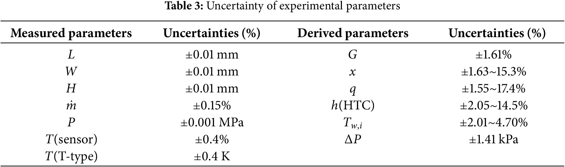
Ri denotes an indirect parameter derived from multiple directly measured parameters Xi. The ambiguity of the indirectly assessed parameters UR can be inferred from the uncertainty of the directly measured variables Uxi. The uncertainties of the parameters utilized in the experiment are delineated in Table 3.
3.1 Validation of Single-Phase Flow
To ensure that all experimental equipment operates within an acceptable accuracy range and the reliability of measurement data prior to conducting flow boiling experiments, it is necessary to perform single-phase verification of the working fluid. The verification technique is employed in the verification formula for the two equations presented in Eqs. (16) and (17). Eq. (16) represents the heat transfer correlation proposed by Gnielinski [30], while Eq. (17) is attributed to Dittus and Boelter [31]. The correlation proposed by Gnielinski is formulated from the experimental data of a single channel, exhibiting a mean absolute error (MAE) of 5.62% in the predicted experimental results; conversely, the correlation presented by Dittus and Boelter is grounded in the experimental data from a substantial number of channels. Dittus and Boelter’s correlation model was developed through empirical fitting of extensive experimental data, yielding an MAE of 18.7% for the experimental results in this domain. As illustrated in Fig. 4. All these instances illustrate the precision and dependability of the flow boiling experimental data employed in this study. The Dittus-Boelter correlation was developed for single-phase flow in conventional channels. Due to the relatively larger heat transfer area in microchannels, the Nusselt number (Nu) obtained in this study during single-phase validation is higher than that predicted by the Dittus-Boelter correlation, indicating enhanced heat transfer performance with a significant deviation. Meanwhile, the Gnielinski correlation was fitted using extensive experimental data, covering both conventional and microchannels, thus exhibiting better universality and a smaller MAE in Nu prediction. However, since this study specifically focuses on microchannels, the experimentally obtained Nu values are higher than those predicted by the Gnielinski correlation.

Figure 4: Comparison between the experimental results of the single-phase flow and the existing correlations [24,30,31]
Fig. 5a illustrates the boiling curves at various mass fluxes. This study indicates that the onset of nucleate boiling (ONB) occurs within a wall superheat range of 2~4 K under the specified experimental conditions. The wall superheat related to the ONB increases concurrently with the mass flux. Conversely, at reduced mass fluxes, the effective heat flux will attain the threshold for heat transfer deterioration more rapidly, as it cannot persist in increasing.


Figure 5: Boiling curves. (a) Boiling curves at different mass flux; (b) Boiling curves at different saturation temperature; (c) Boiling curves at different inlet sub-cooling
Fig. 5b demonstrates the boiling curve at different saturation temperatures. The wall superheat linked to the ONB decreases as the saturation temperature increases. This phenomenon occurs because the working fluid R1234yf has a reduced gas-liquid density ratio at elevated saturation pressures. A reduced wall superheat at which boiling occurs is due to smaller diameter bubbles detaching from the heated wall more rapidly.
Meanwhile, Fig. 5c depicts the comparable boiling curves at various supercooling levels. The trends seen at different sub-cooling levels are identical to those at varying mass fluxes across the range of operational parameters utilized in this experiment. This similarity arises because additional heat must be absorbed for the mass to reach the saturation state at elevated sub-cooling levels. Moreover, increased sub-cooling elevates the fluid’s surface tension, so inhibiting and delaying bubble formation. The extent of sub-cooling exerts minimal influence on the boiling curve under low effective heat flux conditions, resulting in a nearly consistent value along the curve.
The variation of HTC with effective heat flux under different operating conditions is systematically presented in Fig. 6a,c,e, which examine the effects of mass flux, saturation temperature, and subcooling degree, respectively. The experimental results demonstrate a consistent correlation between HTC and effective heat flux across all tested conditions. At low heat fluxes (0–50 kW/m2), single-phase convection dominates the heat transfer process, yielding relatively low HTC values. Upon the ONB, bubble nucleation at the microchannel walls induces a sharp enhancement in HTC, which continues to increase with rising heat flux. The HTC reaches its peak when convective evaporation of the liquid film becomes the primary heat transfer mechanism, while the contribution of nucleate boiling diminishes. Beyond this point, further increases in heat flux promote the formation and expansion of localized dryout regions within the thin liquid film separating the vapor core from the channel walls, leading to a progressive deterioration in HTC. Consistent with our previous findings [24], both R134a and R1234yf exhibit similar HTC trends with increasing heat flux, suggesting analogous flow pattern evolution. As the heat flux rises, the flow regime transitions sequentially from bubbly flow to confined bubbly flow, then to slug flow, and finally to annular flow. This progression corresponds to the gradual expansion of the vapor phase from discrete bubbles to continuous vapor cores, while the liquid phase is confined to a thin film along the channel walls. Consequently, the dominant heat transfer mechanism shifts from nucleate boiling to convective boiling, reflecting the evolving flow structure.

Figure 6: The variation of HTC with effective heat flux and vapor quality. (a) The variation of HTC with effective heat flux at different mass flux; (b) The variation of HTC with vapor quality at different mass flux; (c) The variation of HTC with effective heat flux at different saturation temperature; (d) The variation of HTC with vapor quality at different saturation temperature; (e) The variation of HTC with effective heat flux at different inlet sub-cooling; (f) The variation of HTC with vapor quality at different inlet sub-cooling
Fig. 6a depicts an investigation of the correlation between the HTC and the effective heat flux at different mass fluxes. Results demonstrate that different mass fluxes maintain a negligible effect on the HTC at low effective heat fluxes. When the HTC reaches its maximum, the effective heat flux concurrently increases with the mass flux, as depicted in the figure. Compared to a mass flux of 434 kg/(m2 s), the maximum heat transfer coefficients increase by 20.82% and 32.35% at mass fluxes of 727 and 1015 kg/(m2 s), respectively. This suggests that the effect of mass flux on the HTC becomes more pronounced, indicating that mass flux primarily influences convective evaporation while delaying the decrease in heat transfer at higher mass fluxes. An increased mass flux significantly enhances fluid velocity and turbulence, enabling the rapidly moving fluid to dissipate heat from the wall more efficiently while suppressing bubble coalescence and local dryout. Meanwhile, an increase in mass flux will enhance the shear effect of the liquid, improving the liquid film’s regeneration capacity. This leads to a decrease in or inhibition of the local dryout, resulting in a more uniform liquid film that can reliably cover the heating surface, thereby enhancing the heat transfer coefficient.
Fig. 6c presents the dependence of the HTC on the effective heat flux at different saturation temperatures. The results demonstrate that higher saturation temperatures enhance the HTC, indicating improved heat transfer performance at elevated saturation pressures. At a saturation temperature of 303 K, the HTC reaches its maximum value of 43.81 kW/(m2 K). At lower saturation pressures, the superheat required for bubble nucleation decreases due to the depressed boiling point of the working fluid. However, the lower bubble detachment frequency prolongs bubble residence time on the heated surface, limiting the heat transfer enhancement from nucleate boiling. Conversely, at higher saturation pressures, the working fluid requires greater superheat for bubble nucleation, but the bubble detachment frequency increases significantly. This change reduces bubble residence time while improving the dynamic equilibrium between bubble growth and departure, thereby strengthening the nucleate boiling contribution to heat transfer. Additionally, increased saturation pressure modifies the thermophysical properties of the working fluid, promoting more efficient bubble formation and detachment. Under these conditions, nucleate boiling and convective evaporation act synergistically, substantially improving overall heat transfer performance. The variation in saturation pressure not only governs bubble dynamics but also significantly influences the dominant heat transfer mechanism, ultimately determining system performance.
Fig. 6e illustrates HTC with the effective heat flux along different degrees of sub-cooling. It illustrates that the influence of sub-cooling on the HTC is negligible under conditions of low effective heat flux in the experimental section. In contrast, a higher sub-cooling corresponds to an increased HTC and a postponed onset of heat transfer deterioration when challenged to high effective heat flux, with the HTC achieving its peak value of 54.50 kW/(m2 K) with sub-cooling at 15 K. This can be explained by the fact that the sub-cooling normally does not significantly influence the heat transfer coefficient, whereas the flow boiling is more likely to be completely developed at low inlet sub-cooling levels. During the fully developed boiling, the HTC is rarely impacted by sub-cooling.
Fig. 6b illustrates that, at a specific saturation temperature and sub-cooling, increased mass flux results in a reduced vapor quality when reaching the maximum HTC. The vapor quality corresponding to the maximum heat transfer coefficients range from 0.3 to 0.4 for the three distinct mass fluxes. This happens since, at elevated mass fluxes, the liquid phase flow rate is significant, vapor phase expansion is restricted, bubbles are rapidly evacuated from the channel, and there is a sufficient supply of the liquid phase, leading to reduced vapor quality.
Fig. 6d illustrates the relationship between HTCs and vapor quality at different saturation temperatures. The analysis indicates that convective heat transfer prevails at elevated vapor quality, whereas nucleate boiling is enhanced and convective boiling is diminished at high saturation temperatures. An expedited decline in heat transfer efficiency arises from an increased gas-phase proportion, a reduced latent heat of vaporization, and an accelerated expansion of the dryout area at elevated saturation temperatures. Luo et al. [32] reached a comparable outcome.
Fig. 6f illustrates the correlation between vapor quality and the HTC across different inlet sub-cooling scenarios. The disparity between the inlet sub-cooling 5°C~10 K and 10°C~15 K remains approximately constant. This occurs because of a high degree of inlet sub-cooling to the formation of a bubble nucleation site due to localized superheating near the wall once the liquid enters the heating section. The bubble generation is rapidly compressed by the supercooled mainstream liquid, and the periodic bubble growth and breakup induces convective disturbances, enhances turbulent mixing, and significantly improves the local heat transfer coefficient. The detachment and condensation of bubbles simultaneously disturb the thermal boundary layer and decrease thermal resistance, hence improving heat transfer.
3.4 Wall Temperature Distribution
Fig. 7 illustrates the correlation between the wall temperature and the effective heat flux. It indicates that within the relatively low range of effective heat flux (0–50 kW/m2), the working fluid R1234yf through the parallel microchannels remains a single-phase fluid. Meanwhile, the single-phase R1234yf heat transfer performance fails to satisfy the requirements for wall temperature regulation; an increase in effective heat flux will consequently lead to a rapid rise in the average wall temperature. The improvement in effective heat flux can convert R1234yf from a single-phase fluid into a vapor-liquid two-phase fluid, with the consequent bubble formation causing a significant reduction in the local HTC. This phenomenon would enable the utilization of the latent heat of vaporization of R1234yf to extract a greater amount of heat, thereby effectively augmenting the heat transfer efficiency and resulting in a more substantial reduction in wall temperature concurrently. Once heat transfer deterioration occurs, the flow boiling heat transfer fails to maintain the wall temperature, leading to ineffective cooling and a rapid increase in the wall temperature.


Figure 7: The variation of wall temperature in relation to effective heat flux. (a) The variation of wall temperature with effective heat flux at different mass flux; (b) The variation of wall temperature with effective heat flux at different saturation temperature; (c) The variation of wall temperature with effective heat flux at different inlet sub-cooling
Fig. 7a illustrates the correlation between the wall temperature and the effective heat flux across varying mass fluxes. It is evident that before the heat transfer deterioration, the trends in wall temperature are nearly identical for all three mass fluxes, indicating that the mass fluxes maintain minimal influence on the wall temperature, which remains within the 5–10 K range over the saturation temperature. In addition, when combined with Fig. 6a, it is apparent that increasing the mass flux can postpone the heat transfer deterioration, yet it does not significantly impact the wall temperature itself. The wall temperature is primarily influenced by the saturation temperature of the working fluid before a decrease of heat transfer, which is defined as nucleate boiling, and variations in mass flux do not directly affect the saturation temperature. Simultaneously, during the annular flow pattern, an increased mass flux increases inertial forces, resulting in a more uniform distribution of the liquid film and postponing local dryout. The breakdown of liquid film is the main reason for heat transfer deterioration, whereas elevated mass flux may inhibit the initial evaporation of the liquid film.
Fig. 7b illustrates the relationship between the wall temperature and effective heat flux at various saturation temperatures. It is obvious that saturation temperature significantly influences wall temperature; as saturation temperature increases, the wall temperature corresponding to the same effective heat flux also rises. Furthermore, before the degradation of heat transfer, the wall temperature remains within 5 to 10 K over the saturation temperature. The annular flow enhances heat transfer resistance, while the reduction in liquid density results in an increased thermal boundary layer thickness. Consequently, the heat transfer efficiency at the gas-liquid interface diminishes, and the interface thermal resistance escalates, resulting in a decrease in overall heat transfer efficiency. This requires higher wall temperatures to sustain the same effective heat flux.
Fig. 7c illustrates that the influence of inlet sub-cooling on wall temperature and mass flux is analogous; an increase in inlet sub-cooling can mitigate the degradation of heat transfer, and prior to achieving the two-phase flow state, it contributes to a reduction in wall temperature. This occurs since, when the effective heat flux is low, heat transfer is relatively uniform, resulting in a minimal temperature gradient throughout the microchannel; thus, the influence of the inlet sub-cooling on the wall temperature is correspondingly low. As effective heat flux increases, heat transfer within the microchannel increases, leading to a greater temperature gradient, consequently increasing the influence of the inlet sub-cooling. Higher inlet sub-cooling enables the fluid to absorb additional heat within the microchannel, facilitating a decrease in the wall temperature.
Fig. 8 presents the pressure drop characteristics across the microchannel heat sink as a function of effective heat flux under varying operating conditions, including mass flux, saturation temperature, and inlet subcooling. At fixed mass flux, saturation temperature, and subcooling conditions, the total pressure drop increases monotonically with heat flux, reaching a maximum value of 0.0361 MPa. At low heat fluxes, the flow regime is predominantly bubbly flow, where discrete vapor bubbles are dispersed in the continuous liquid phase. In this flow regime, the pressure drop arises mainly from liquid phase frictional dissipation. As the heat flux increases, the flow pattern transitions to confined bubbly flow, representing an intermediate state between bubbly and slug flow regimes. This transitional state exhibits progressive bubble coalescence while maintaining incomplete vapor phase occupation of the channel cross-section. This transition introduces significant vapor-liquid interfacial effects that contribute to the pressure drop. Further increases in heat flux led to slug flow formation, where the pressure drop exhibits a sharp rise due to enhanced interfacial friction between alternating vapor and liquid slugs, coupled with flow acceleration effects. At the highest heat fluxes, annular flow becomes established, characterized by a continuous vapor core surrounded by a thin liquid film along the channel walls. In this regime, the pressure drop is dominated by vapor-phase flow resistance and interfacial shear stresses at the vapor-liquid boundary. These observations align with the findings of Thiangtham et al. [33], who attributed the pressure drop escalation to increased bubble nucleation rates and void fraction at higher heat loads. The consequent vapor phase expansion and flow acceleration collectively contribute to the overall pressure drop enhancement.
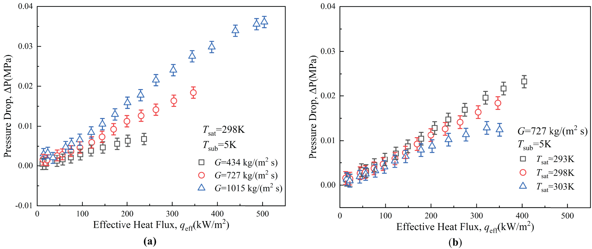

Figure 8: The variation of pressure drops with effective heat flux. (a) The variation of pressure drops with effective heat flux at different mass flux; (b) The variation of pressure drops with effective heat flux at different saturation temperature; (c) The variation of pressure drops with effective heat flux at different inlet sub-cooling
As illustrated in Fig. 8a, for identical effective heat flux, saturation temperature, and sub-cooling. The overall pressure drop escalates with an increase in mass flux. Lee and Karayiannis [34] highlighted that the shear stress at the vapor-liquid interface escalates with the rising mass flux of the working fluid, resulting in large frictional and acceleration pressure drop.
Fig. 8b illustrates that the total pressure drop decreased with saturation temperature increases, given a specific mass flux, sub-cooling, and effective heat flux. For instance, with G = 727 kg/(m2 s) and qeff = 120.0 kW/m2, the pressure drops at Tsat = 293, 298, and 303 K are 0.00713, 0.00598, and 0.00537 MPa, respectively. Xu et al. [35] determined that this phenomenon is attributable to the reduction in saturation pressure, which leads to a rise in the vapor-liquid density ratio, liquid viscosity, and evaporation rate. Consequently, as the vapor-liquid phase volume ratio escalates, the gas-phase flow rate and the frictional pressure drop both grow. When the effective heat flux reaches 350 kW/m2, heat transfer has deteriorated at saturation temperatures of 293 and 298 K. Currently, there are significant fluctuations in the instantaneous pressure drop, leading to greater flow instability. The data illustrated in the figure represents 3-min average values. The significant variations result in a reduction of the mean pressure drop, though do not conflict with the general rule that the pressure drop escalates with the effective heat flux before the onset of heat transfer deterioration.
Fig. 8c illustrates that, under identical saturation temperature and mass flux conditions, the sub-cooling has negligible impact on the inlet and outlet pressure drop. This is attributable to the fact that the inlet sub-cooling simply influences the length of the subcooled zone, where the frictional pressure drop is typically less than that in the saturation zone. The acceleration pressure drop is primarily influenced by vapor expansion and velocity alterations, whereas the degree of inlet sub-cooling exerts minimal influence on these factors. Consequently, its effect on the overall pressure drop is negligible, indicating that variations in subcooling degree do not significantly impact the inlet and outlet pressure drops within the sub-cooling range utilized in this research.
3.6 Evaluation of Existing Correlations
The heat transfer results obtained in this study were compared with selected six existing correlations in the literature. Table 4 and Fig. 9 illustrate a comparison of the correlations. Eq. (18) is employed for its computation.
where, N denotes the number of expected data points.


Figure 9: Comparisons of flow boiling HTC between experimental results and the predicted values of correlations constructed by (a) Lazarek and Black [40]; (b) Sun and Mishima [38]; (c) Li and Wu [37]; (d) Thiangtham et al. [36]; (e) Dalkılıç et al. [41]; (f) Fang [39]
The correlation developed by Thiangtham et al. [36] was employed to predict the HTC under the current conditions, resulting in a predicted value of 91.13% for the heat transfer coefficient. R134a was utilized in multi-microchannels with a small Dh (0.421 mm) characterized by low mass, heat fluxes, and low saturation temperatures; Li and Wu model anticipated a value of 59.75% [37].
Sun and Mishima [38] constructed a correlation utilizing 2505 data points. This correlation was employed to predict the HTC at 26.15% based on the experimental results. Fang [39] identified a connection resulting in 15.57%. With the appropriate effective heat flux, outcomes can be achieved with considerable accuracy. Nevertheless, when the effective heat flux increases, the accuracy of predictions diminishes. However, it possesses exceptional compatibility and an extensive database. The correlation formulated by Lazarek and Black [40] exhibit diminished efficacy when applied to large HTCs, as it is predicated on correlations for relatively moderate heat fluxes and mass fluxes. The minimal MAE, 15.37%, is identified in the correlation formulated by Dalkılıç et al. [41].
The existing correlations were developed based on working fluids other than R1234yf. Although R134a exhibits similar heat transfer characteristics to R1234yf, the current correlations still demonstrate notable deviations in predicting the HTC of R1234yf, as illustrated in Fig. 10b. To address this limitation, this study modifies the exponents and coefficients of the well-performing existing correlation through regression analysis, thereby developing a new correlation that provides more accurate predictions for HTC of R1234yf. This study focuses on enhance the predictive accuracy of experimental data, drawing upon the correlation models established by Dalkılıç et al. [41] and Lazarek and Black [40]. This research utilizes two critical dimensionless numbers, the Reynolds number (Re) and the Bond number (Bo), to clarify and define the two-phase flow and heat transfer characteristics within the microchannel. The Reynolds number characterizes the ratio of inertial force to viscous force, whereas the Bond number characterizes the ratio of gravitational force to surface tension. This study establishes the vapor-liquid density ratio as a correction factor to enhance the applicability and accuracy of the correlation, building upon traditional dimensionless numbers to more accurately represent the influence of the physical properties of the gas-liquid two-phase on flow and heat transfer behavior. During the construction of the correlation, the nonlinear curve fitting function was employed for regression analysis based on the experimental data, resulting in the following correlation:

Figure 10: The verification of (a) the proposed correlation (b) all correlations based on the present experimental data [36–41]
Fig. 10a illustrates the comparison between the predicted values with empirical correlation and the experimentally measured data from the present work. The correlation demonstrates superior reliability and predicted stability, as it incorporates a wide variety of effective heat flux, mass flux, elevated saturation temperature, and flow channel dimensions. This model can likewise predict the experimental results with a mean absolute error of 5.75%, and 93.42% of the predicted values derived from the correlation formula fall within MAE of 15% of the saturation temperature. This research systematically analyzed the prediction performance of the newly developed correlation by plotting the prediction data of all correlations on Fig. 10b and comparing it with those commonly utilized in existing research. The predicted data points of the new correlation styles are more closely aligned with the 45° reference line, signifying improved concordance between their expected and experimental values. The predicted data points of the current correlations demonstrate considerable dispersion, particularly in the low and high effective heat flux areas, where prediction errors escalate significantly.
Despite the advantages of the newly formulated correlation, its applicability is restricted to the dimensionless number range, based upon the limited data available for this study and the consideration of only the experimental results of this correlation:
This research also verifies the efficiency of the correlation using experimental data from Dalkılıç et al. [41] and Criscuolo et al. [19]. Fig. 11 illustrates that the MAE is 7.31% and 8.53%, respectively, with most of the newly created correlation predictions falling within MAE of 15%, indicating a commendable level of accuracy. Table 5 outlines the range of working conditions alongside the quantity of data obtained from the references.

Figure 11: The verification of the proposed correlation based on Dalkılıç et al. [41] and Criscuolo et al.’s [19] experimental data

In present study, an aluminum-based microchannels heat sink including 27 parallel microchannels with hydraulic diameter of 0.89 mm to experimentally investigate the flow boiling characteristics of the eco-friendly refrigerant R1234yf. The objective is to enhance the heat transfer prediction model and methodically investigate the impacts of mass flux, saturation temperature, and sub-cooling on heat transfer and pressure drop. The subsequent are the principal conclusions:
(1) High heat flux boiling is depending on mass flux. The experimental findings indicate that ONB initiates at a wall superheat of 2–4 K over the three mass fluxes and escalates with increasing mass flux. At low effective heat flux, the three curves nearly align, indicating that mass flux has minimal impact on the heat transfer coefficient. In conditions of high effective heat flux, a rise in mass flux enhances the heat transfer coefficient. The mass flux does not significantly influence the wall temperature. Consequently, increasing mass flux merely tends to decelerate the heat transfer deterioration. The inlet and outlet pressure drop escalates with mass flux, under constant effective heat flux, saturation temperature, and sub-cooling.
(2) As the saturation temperature increases, smaller diameter bubbles detach from the heated wall surface more rapidly, facilitating the boiling process at reduced superheat levels. Simultaneously, an increase in saturation temperature correlates with a rise in the maximum HTC and a more significant enhancement of heat transfer. At higher saturation temperatures, heat transfer is enhanced due to the increased frequency of bubble separation. Before the heat transfer deterioration, the rise in saturation temperature resulted in a slight enhancement of the heat transfer coefficient. Furthermore, when the heat load persists in escalating uncontrollably, the HTC diminishes more rapidly after reaching the peak, resulting in a more severe at elevated saturation temperatures. Simultaneously, there is a more significant rise in the wall temperature as the saturation temperature escalates. For a specific mass flux, subcooling, and effective heat flux, the total pressure drop reduces as the saturation temperature rises.
(3) Higher sub-cooling corresponds to a diminished wall superheat at the ONB. The influence of sub-cooling on the HTC is minimal at low effective heat flux. Higher sub-cooling relates to an increased heat transfer coefficient, and it postpones heat transfer deterioration at higher effective heat flux. Overall, the sub-cooling does not significantly impact the heat transfer coefficient. Before the heat transfer deterioration, the HTC rises with an increase in sub-cooling; however, the differences in the HTC between subcooling of 5–10 K and 10–15 K is basically constant. The influence of sub-cooling contributes to a decrease in wall temperature. At lower subcooling levels, variations in sub-cooling barely affect the inlet and outlet pressure drops.
(4) The reliability of existing HTC correlations was evaluated based on the mean absolute error (MAE) between predicted and experimental data. The results show that the correlation proposed by Dalkılıç et al. [41] provides the most suitable framework for this study. By incorporating the vapor-to-liquid density ratio to account for saturation temperature effects, a modified correlation was developed, applicable to the present experimental conditions. However, its applicability is constrained by the following dimensionless parameter ranges:
This study’s improved heat transfer correlation for R1234yf in microchannel cooling systems provides practical guidance for high-heat-flux applications. Key recommendations include: (1) using vapor chambers to prevent localized overheating, (2) real-time CHF monitoring to maintain stable operation, and (3) flow rate adjustment to sustain bubbly flow for balanced heat transfer and pressure drop. These strategies benefit high-power electronics like 3D-stacked processors and 5G base stations, improving cooling efficiency while reducing energy consumption. The correlation also supports adapting designs to advanced manufacturing methods, promoting sustainable cooling solutions.
Acknowledgement: Not applicable.
Funding Statement: This research was supported by the Beijing Municipal Science & Technology Commission (Z231100006123010).
Author Contributions: The authors confirm contribution to the paper as follows: Conceptualization, Ying Zhang and Chao Dang; formal analysis, Ying Zhang; investigation, Ying Zhang; resources, Ying Zhang and Zhiqiang Zhang; data curation, Ying Zhang; writing—original draft preparation, Ying Zhang; writing—review and editing, Chao Dang and Zhiqiang Zhang; supervision, Chao Dang; project administration, Chao Dang. All authors reviewed the results and approved the final version of the manuscript.
Availability of Data and Materials: The data that support the findings of this study are available from the corresponding author upon reasonable request.
Ethics Approval: Not applicable.
Conflicts of Interest: The authors declare no conflicts of interest to report regarding the present study.
Nomenclature
| A | Area, [mm2] |
| Bd | Bond number |
| Bo | Boiling number |
| Cp | Specific heat capacity at constant pressure, [kJ/kg ⋅ K] |
| D | Depth, [mm] |
| Dh | Hydraulic diameter, [mm] |
| Fa | |
| G | Mass velocity, [kg/m2 s] |
| h, HTC | Heat transfer coefficient [kW/m2 K] |
| H | Height, [mm] |
| hlv | Latent heat of vaporization |
| k | Thermal conductivity, [mW/m K] |
| L | Length, [mm] |
| MAE | Mean absolute error |
| m | Fin parameter |
| Mass flux, [kg/s] | |
| N | Number of channels, number of data points, [-] |
| Nu | Nusselt number, [-] |
| P | Pressure, [MPa] |
| Pr | Prandtl number, [-] |
| Q | Input power, [W] |
| q | Heat flux, [W/cm2] |
| Ra | Roughness |
| Re | Reynolds number, [-] |
| T | Temperature, [K] |
| W | Width, [mm] |
| We | Duration of bubble growth stage (s) |
| x | Vapor quality, [-] |
| z | Axial distance, [mm] |
| Greek Symbols | |
| Vertical distance [mm] | |
| Viscosity, [μPa s] | |
| Surface tension, [mN/m] | |
| Fin efficiency, [-] | |
| Density, [kg/m3] | |
| Total pressure drop, [MPa] | |
| Subscripts | |
| al | Aluminum |
| avg | Averaged value |
| b | Base |
| ch | Channel |
| co | Copper |
| exp | Experiment |
| eff | Effective |
| in | Inlet |
| l | Liquid |
| out | Outlet |
| pre | Predicted |
| sat | Saturation |
| v | Vapor |
| w | Wall |
References
1. Mathew J, Krishnan S. A review on transient thermal management of electronic devices. J Electron Packag. 2022;144(1):010801. doi:10.1115/1.4050002. [Google Scholar] [CrossRef]
2. Patra CK, Bhattacharya A, Das PK. Heat transfer characteristics of acetone and methanol flow boiling in parallel microchannel heat sink: a parametric study and assessment of predictive correlations. Appl Therm Eng. 2025;270:126217. doi:10.1016/j.applthermaleng.2025.126217. [Google Scholar] [CrossRef]
3. He Z, Yan Y, Zhang Z. Thermal management and temperature uniformity enhancement of electronic devices by micro heat sinks: a review. Energy. 2021;216(1):119223. doi:10.1016/j.energy.2020.119223. [Google Scholar] [CrossRef]
4. Ning L, Liu Q, Yang F, Jin M. Research progress of electronic device cooling technolog. Refrig Air-Cond. 2021;21(12):1–7. [Google Scholar]
5. Zheng H. Microchannel flow boiling cooling technology and application. J Technol. 2023;23(03):195–9. [Google Scholar]
6. Odumosu OA, Wang T, Che Z. Dynamics of vapor bubble train in flow boiling heat transfer in microchannels. Int Commun Heat Mass Transf. 2025;164(2):108859. doi:10.1016/j.icheatmasstransfer.2025.108859. [Google Scholar] [CrossRef]
7. Fang Y, Lu D, Yang W, Yang H, Huang Y. Saturated flow boiling heat transfer of R1233zd(E) in parallel mini-channels: experimental study and flow-pattern-based prediction. Int J Heat Mass Transf. 2023;216(1):124608. doi:10.1016/j.ijheatmasstransfer.2023.124608. [Google Scholar] [CrossRef]
8. Kokate R, Park C, Mitsingas C, Schroen E. Flow boiling in parallel microchannels in a pumped two-phase loop: flow visualization and thermal characteristics. Int Commun Heat Mass Transf. 2024;155:107566. doi:10.1016/j.icheatmasstransfer.2024.107566. [Google Scholar] [CrossRef]
9. Zhang Z, Zhang G, Zhang Y, Tian M. Experimental study on the effect of hydraulic diameter on the flow boiling characteristics in microchannels. Int J Heat Mass Transf. 2025;241(10):126736. doi:10.1016/j.ijheatmasstransfer.2025.126736. [Google Scholar] [CrossRef]
10. Li L, Guo Y, Zhang B, Guo X, Yang Z. Experimental investigation of flow boiling heat transfer in microchannels with inlet two-phase flow effects. Int J Heat Mass Transf. 2025;239:126610. doi:10.1016/j.ijheatmasstransfer.2024.126610. [Google Scholar] [CrossRef]
11. Lee VYS, Karayiannis TG. Influence of system pressure on flow boiling in microchannels. Int J Heat Mass Transf. 2023;215(3):124470. doi:10.1016/j.ijheatmasstransfer.2023.124470. [Google Scholar] [CrossRef]
12. Huang Y, Chen K, Tang X, Fang Y. Two-phase flow oscillation and distribution in parallel channels during R1233zd(E) subcooled flow boiling: a numerical study. Int J Heat Mass Transf. 2024;218:124778. doi:10.1016/j.ijheatmasstransfer.2023.124778. [Google Scholar] [CrossRef]
13. Kurose K, Kawasuso T, Miyata K, Hamamoto Y. Simulation model of boiling heat transfer and flow maldistribution in parallel mini-channels heated unequally. Int J Heat Mass Transf. 2022;195(2):123184. doi:10.1016/j.ijheatmasstransfer.2022.123184. [Google Scholar] [CrossRef]
14. Guo Y, Li L, Zhang B, Guo X. Numerical study of bubble growth and flow boiling characteristics in open microchannels with different gap height. Appl Therm Eng. 2025;265(85):125567. doi:10.1016/j.applthermaleng.2025.125567. [Google Scholar] [CrossRef]
15. Odumosu OA, Ye M, Wang T, Che Z. Interaction between vapor bubbles during flow boiling heat transfer in microchannels. Int J Heat Mass Transf. 2025;238(1):126443. doi:10.1016/j.ijheatmasstransfer.2024.126443. [Google Scholar] [CrossRef]
16. Yuan C, Jin S, Li H, Liu Z, Peng J, Li H. Experimental study of R134a and its alternative mixture R450A flow boiling in a microchannel tube. Int Commun Heat Mass Transf. 2024;159(1):108319. doi:10.1016/j.icheatmasstransfer.2024.108319. [Google Scholar] [CrossRef]
17. Roldão TCB, Tibiriçá CB. Flow boiling pressure drop and heat transfer at high mass fluxes for R514a in a single microchannel. Appl Therm Eng. 2024;254(1):123807. doi:10.1016/j.applthermaleng.2024.123807. [Google Scholar] [CrossRef]
18. Liu H, Wu Z, Yuan C, Li H, Li H, Peng J, et al. Experimental study of R410A and its low GWP alternative R452B flow boiling in a multiport microchannel tube. Int J Heat Mass Transf. 2024;230:125732. doi:10.1016/j.ijheatmasstransfer.2024.125732. [Google Scholar] [CrossRef]
19. Criscuolo G, Colombo LPM, Kanbur BB, Markussen WB, Ryhl Kærn M. Heat transfer and pressure drops during high heat flux flow boiling of low-GWP refrigerants in 200 μm-wide multi-microchannels. Int J Heat Mass Transf. 2024;220:124882. doi:10.1016/j.ijheatmasstransfer.2023.124882. [Google Scholar] [CrossRef]
20. Criscuolo G, Markussen WB, Meyer KE, Kærn MR. High heat flux flow boiling of R1234yf, R1234ze(E) and R134a in high aspect ratio microchannels. Int J Heat Mass Transf. 2022;186(15):122215. doi:10.1016/j.ijheatmasstransfer.2021.122215. [Google Scholar] [CrossRef]
21. Li H, Hrnjak P. Heat transfer coefficient and pressure gradient of R32 and R1234yf mixtures flow boiling in a microchannel tube. Int Commun Heat Mass Transf. 2022;134:106043. doi:10.1016/j.icheatmasstransfer.2022.106043. [Google Scholar] [CrossRef]
22. Kærn MR, Criscuolo G, Meyer KE, Markussen WB. Critical heat flux characteristics of R1234yf, R1234ze(E) and R134a during saturated flow boiling in narrow high aspect ratio microchannels. Int J Heat Mass Transf. 2021;180(1):121840. doi:10.1016/j.ijheatmasstransfer.2021.121840. [Google Scholar] [CrossRef]
23. Salman M, Dhamodharan P, Kim SC. Thermal-hydraulic performance of R1234yf in brazed plate heat exchanger at low saturation temperature and mass flux conditions: experimental investigation. Appl Therm Eng. 2025;258(B):124634. doi:10.1016/j.applthermaleng.2024.124634. [Google Scholar] [CrossRef]
24. Zhang Z, Jia L, Dang C, Ding Y. Experimental study on flow boiling characteristics of R134a inside high-heat-flux microchannels. Int J Heat Fluid Flow. 2024;107(19–20):109372. doi:10.1016/j.ijheatfluidflow.2024.109372. [Google Scholar] [CrossRef]
25. Lemmon EW, Bell IH, Huber ML, McLinden MO. NIST Standard Reference Database 23: Reference Fluid Thermodynamic and Transport Properties-Refprop, Version 10.0. Gaithersburg, MD, USA: National Institute of Standards and Technology, Standard Reference Data Program; 2018. [Google Scholar]
26. Wang S, Xia G, Cheng L, Ma D. Experimental study and visualization of flow boiling in open microchannels with laser-etched micro-nanoscale composite fins. Int J Heat Mass Transf. 2025;246:127068. doi:10.1016/j.ijheatmasstransfer.2025.127068. [Google Scholar] [CrossRef]
27. Ng ECJ, Hung YM. Enhanced subcooled flow boiling in microchannels integrated with nanoporous graphene coatings of distinctive wettability. Int J Heat Mass Transf. 2025;246:127065. doi:10.1016/j.ijheatmasstransfer.2025.127065. [Google Scholar] [CrossRef]
28. Choi T, Kim TY. Flow boiling performance of T-shaped microchannels with sudden-expansion flow passages. Appl Therm Eng. 2025;274:126568. doi:10.1016/j.applthermaleng.2025.126568. [Google Scholar] [CrossRef]
29. Moffat RJ. Describing the uncertainties in experimental results. Exp Therm Fluid Sci. 1988;1(1):3–17. [Google Scholar]
30. Gnielinski V. New equations for heat and mass transfer in turbulent pipe and channel flow. Int Chem Eng. 1976;16(2):359–68. [Google Scholar]
31. Dittus FW, Boelter LMK. Heat transfer in automobile radiators of the tubular type. Int Commun Heat Mass Transf. 1985;12(1):3–22. doi:10.1016/0735-1933(85)90003-x. [Google Scholar] [CrossRef]
32. Luo X, Xia Y, Huang J, He J, Tu J, Chen J, et al. Experimental investigation on high-temperature flow boiling heat transfer characteristics of R245fa in a horizontal circular tube. Appl Therm Eng. 2023;225(3):120260. doi:10.1016/j.applthermaleng.2023.120260. [Google Scholar] [CrossRef]
33. Thiangtham P, Mondal PK, Wongwises S. Flow boiling pressure drop characteristics in a multi-microchannel heat sink. Phys Fluids. 2021;33(1):012004. doi:10.1063/5.0036615. [Google Scholar] [CrossRef]
34. Lee VYS, Karayiannis TG. Effect of inlet subcooling on flow boiling in microchannels. Appl Therm Eng. 2020;181(2):115966. doi:10.1016/j.applthermaleng.2020.115966. [Google Scholar] [CrossRef]
35. Xu Y, Yan Z, Li L. Flow boiling heat transfer, pressure drop and flow patterns of the environmentally friendly refrigerant R1234yf for cooling avionics. Appl Therm Eng. 2022;209:118301. doi:10.1016/j.applthermaleng.2022.118301. [Google Scholar] [CrossRef]
36. Thiangtham P, Keepaiboon C, Kiatpachai P, Asirvatham LG, Mahian O, Dalkilic AS, et al. An experimental study on two-phase flow patterns and heat transfer characteristics during boiling of R134a flowing through a multi-microchannel heat sink. Int J Heat Mass Transf. 2016;98:390–400. doi:10.1016/j.ijheatmasstransfer.2016.02.051. [Google Scholar] [CrossRef]
37. Li W, Wu Z. A general correlation for evaporative heat transfer in micro/mini-channels. Int J Heat Mass Transf. 2010;53(9):1778–87. doi:10.1016/j.ijheatmasstransfer.2010.01.012. [Google Scholar] [CrossRef]
38. Sun L, Mishima K. An evaluation of prediction methods for saturated flow boiling heat transfer in mini-channels. Int J Heat Mass Transf. 2009;52(23):5323–9. doi:10.1016/j.ijheatmasstransfer.2009.06.041. [Google Scholar] [CrossRef]
39. Fang X. A new correlation of flow boiling heat transfer coefficients based on R134a data. Int J Heat Mass Transf. 2013;66(2):279–83. doi:10.1016/j.ijheatmasstransfer.2013.07.015. [Google Scholar] [CrossRef]
40. Lazarek GM, Black SH. Evaporative heat transfer, pressure drop and critical heat flux in a small vertical tube with R-113. Int J Heat Mass Transf. 1982;25(7):945–60. doi:10.1016/0017-9310(82)90070-9. [Google Scholar] [CrossRef]
41. Dalkılıç AS, Özman C, Sakamatapan K, Wongwises S. Experimental investigation on the flow boiling of R134a in a multi-microchannel heat sink. Int Commun Heat Mass Transf. 2018;91:125–37. doi:10.1016/j.icheatmasstransfer.2017.12.008. [Google Scholar] [CrossRef]
Cite This Article
 Copyright © 2025 The Author(s). Published by Tech Science Press.
This work is licensed under a Creative Commons Attribution 4.0 International License , which permits unrestricted use, distribution, and reproduction in any medium, provided the original work is properly cited.
 Downloads
 Citation Tools