
 Submit a Paper
 Propose a Special lssue
 Open Access
ARTICLE
NACA Airfoils as Proposal for Heat Sink Fins: Optimization Investigation
Department of Mechanical Engineering, University of Guanajuato, Salamanca, 36787, Mexico
* Corresponding Author: Yanan Camaraza-Medina. Email:
(This article belongs to the Special Issue: Advances in Heat and Mass Transfer: Integrating Numerical Methods with Artificial Intelligence, Machine Learning, and Data-Driven Approaches)
Frontiers in Heat and Mass Transfer 2025, 23(4), 1165-1183. https://doi.org/10.32604/fhmt.2025.067466
Received 04 May 2025; Accepted 17 June 2025; Issue published 29 August 2025
 View Full Text
 Download PDF
Abstract
This work presents a simulation analysis using a multi-objective evolutionary algorithm for the thermo-hydraulic behavior of staggered heat sinks whose fins have NACA 0040 airfoil profile. The results were compared with a conventional pin fin heat sink with a circular profile. This study searched for the best thermo-hydraulic performance by translational and rotational positioning of the fins. It is worth mentioning that this work was carried out in two stages. In the first stage, the thermo-hydraulic behavior of the heat sink was studied moving the location of the upper array above the X-axis from −2.25 to 2.25 mm and above the Y-axis from −1.55 to 1.275 mm. The second stage examined the effects of fin rotation considering the results found in stage 1. However, in this second stage, both arrays were free to rotate. For the upper array, the rotation range was −25° to 25° and for the lower array the rotation range was −15° to 15°. It is worth mentioning that both stages were analyzed for a single Reynolds (Re) number value of 13,000. The optimization results using the multi-objective evolutionary algorithm showed that compared to a NACA 0040 heat sink with fixed, unrotated original configuration (C0), the NACA 0040 heat sink with any Position Configuration (PC) did not significantly improve the heat transfer. Then, the results found in the second stage showed that the effect of the rotation of both sets did not influence the increase in pressure drop. However, it was found that with the Optimal Position and Rotation Configuration (PRCoptimal), which is the optimized array from Stage 1 (position) then optimized by rotation, there is a slightly higher Performance Evaluation Criterion (PEC) compared to the original C0 configuration by 7%. Finally, the proposed NACA 0040 heat sink with the optimal rotation and position setting (PRCoptimal) was found to have a PEC of 9% compared to a conventional pin fin heat sink.Keywords
Over the past few decades, the electronics industry has experienced significant technological advances that have led to innovations and improvements in electronic devices. This progress has resulted in a trend towards miniaturization of these electronic devices. Primarily, the weight and size have been substantially reduced. The main problem is the high concentration of heat generation due to the Joule effect, which hurts the operation and performance of the equipment.
The main solution to address heat generation is the use of heat sinks (HS); essentially a set of fins embedded in a thermal plate and its fundamental role is to exchange and dissipate the heat generated by the processing chip of electronic equipment to the environment and thus effectively reducing the temperature of the chip itself [1]. However, HSs face challenges that limit their proper operation.
One of these challenges is the limited space inside the electronic devices. That is, the primary function of the HS is to transfer the extracted heat to a fluid through its surface, which requires a considerable volume, resulting in an increase in mass. Therefore, a wide variety of geometric configurations, made of various materials and subjected to different flow regimes, are available as options for the HS.
In the technical literature, there are several studies on HSs, with the main contribution being the fin innovation. Historically, the first geometric configurations of heat sinks were Plate Fin Heat Sinks (PFHS). However, the main problem with PFHSs is their low capacity to dissipate large amounts of heat. Therefore, why Rao et al. [2] attempted to improve the thermal performance of these heat sinks by optimizing the design of the plate fins. They found that by varying the base angle of the Plate Fin (PF) and proposing a tilted PF, the thermal performance could be improved by 30%. On the other hand, Pujol et al. [3] also studied the PFHS configuration. They found that by maintaining the inter-plate spacing and increasing the fin thickness, they were able to improve the thermal performance of the HS. An innovative proposal in PFHS design is the one presented by Adeel Tariq et al. [4]. They made significant modifications to the flat plate fins by incorporating multiple perforations and slots along the fins, which increased the heat transfer coefficient and a significant reduction in pressure.
On the other hand, Freegah et al. [5] proposed to increase the wetted surface area and reduce the material by modifying the channels with two designs, which resulted in a 25% reduction in temperature, 29% reduction in thermal resistance, and 34% increase in Nusselt number compared to a conventional PFHS. On the other hand, Nilpueng et al. [6] explored another alternative. They combined the PFHS with a Pin Fin Heat Sink (PiFHS) by modifying the shape of the pin fin and found that this increased the heat increased and also improved the pressure drop. On the other hand, Pandey et al. [7] compared rectangular fins with plate fins and found that under the same conditions, rectangular fins have lower thermal resistance, however, greater energy is required in the distribution of the fluid.
On the other hand, there are pin fin heat sinks. This variation has been widely studied due to its geometrical versatility, i.e., the pin fin profile can take any shape. In addition, the versatility of pin fin heat sinks is advantageous for innovation. Geometric design parameters that can be considered in a heat sink include the number of fins, fin diameter, longitudinal spacing, fin height, and transverse spacing [8].
A proposed trend in pin fin geometry is the implementation of thin plates connected as splitters in a plate and fin heat sinks. This proposal mitigates flow separation and reduces pressure drop [9–11]. In the same manner, Hosseinirad et al. [12] analyzed the effects of straight, corrugated, and curved plate configurations with pin fins on hydrothermal performance; they found the optimal positioning of splitters. Abadi et al. [13] tried to understand the effect of the rotation angle of the splitters attached to the pin fins.
Another proposal is that of Maji et al. [14]. They investigated how to improve heat dissipation through perforated fins by systematically varying the number and size of the perforations, in addition to proposing different geometric shapes of the heat sink base plate. They found that the perforations not only help reduce pressure drop but also improve heat transfer. In this sense, a design proposal is the combination of perforated fins with the inclusion of thin plates, as in the work presented by Huang and Huang [15], where they vary the diameter of the pin fins, the diameter of the perforations and also the length of the splitter added at the end of the pin fins, with the aim of maximizing the thermal performance while keeping the volume fixed.
On the other hand, Shen et al. [16] conducted a study focused on improving the heat transfer at the trailing edge of a turbine blade. In their research, they present a Kagome lattice geometric structure as an alternative and innovative geometry for the use of fins in heat dissipation. It is worth noting that the overall heat transfer rate increased significantly from 6% to 71% with the use of this structure.
In conjunction with these significant improvements in heat transfer, there are aerodynamic alternatives that have low resistance to fluid flow, i.e., they tend to reduce pressure drop, as is the case with NACA profile fins. In addition, it is possible to promote heat transfer as a function of angle. An advantage of these fins is their ease of machining based on a reliable profile equation [17–20].
Moreover, Mehrpooya et al. [21] show how simple geometries such as flat fins, sharp fins or pin fins, can improve heat dissipation by using Phase Change Materials (PCM). They show how PCMs quickly stabilize a sudden change of temperature, and how they can store energy and later release it gradually. These materials, combined with an adequate pin array configuration, can lead to a better thermal management in the heating and cooling of buildings, high-performance heat exchangers, and energy store systems for renewable sources.
In the present work, the use of NACA profiles is proposed. The fundamental reason for the use of the NACA profile in aeronautics is the smooth curvature of its design, which facilitates optimum fluid flow. In other words, it minimizes aerodynamic drag and maximizes lift. In addition, the NACA airfoil has the ability to prevent the formation of undesirable turbulence zones, which is beneficial for aircraft visibility. The main idea to use this NACA profiles, is not the lift, of course, but to minimize aerodynamic drag and turbulence formation while maximizing heat transfer. Thus, the main objective of this work is to improve the heat transfer of a system by implementing the NACA 0040 airfoil profile.
This work attempts to revamp the search for heat sink arrays in a sequential/intuitive fashion using a multi-objective algorithm that weighs the pressure drop and the heat dissipation, directly affecting the performance evaluation criteria (PEC). This work was carried out in two steps: first, the influence of the fins position was studied, and once the best configuration was found, the next step was to study the rotation effect for this configuration. Thus, this method aims to optimize the arrangement in a more refined and profound way, as compared to the conventional methods.
This section shows the analysis, pinpointing the geometry complexity, boundary conditions, assumptions taken, and the governing equations.
The main objective of this work is to improve the heat transfer of a heat dissipation system, therefore the geometry of interest in this work consists of a heat sink NACA 0040 profile fins. The material used in this heat sink is an aluminum alloy (A5083P), which has a thermal conductivity of 167 [W/(m·K)], while the working fluid used was air at 20°C. The dimensions of the NACA profile of each fin are shown in Fig. 1a. In order to reduce the calculation time and thus study the geometric characteristics of the heat sink, only a fraction of the total geometry was simulated. It should be noted that the heat sink has a total of 12 fins. Each fin has a height (

Figure 1: Dimensions of the: (a) NACA fin and (b) fraction of the total geometry of the heat sink
On the other hand, the displacement of the fins is proposed randomly. It is worth noting that the positioning of these fins will only apply to the upper arrangement, the lower arrangement will remain in place. Both arrangements are shown in Fig. 2a. The six fins upper arrangement is marked in red, while the fins lower arrangement is marked in blue.

Figure 2: Heat sink with a NACA fin. (a) delineation of the upper and lower arrangement, (b) origin of displacement on the x-axis, (c) origin of displacement on the y-axis, and (d) origin of displacement on the z-axis
In addition, the vertical and horizontal displacement of each fin begins at the leading edge of the NACA profile, as shown in Fig. 2b,c. In addition, Fig. 2d shows the location of the center of rotation of the NACA profile.
The following boundary conditions were used for the numerical solution of the models:
• Constant and uniform heat flow at the base of the heat sink.
• Constant fluid velocity at the heat sink inlet.
• Manometric pressure at the heat sink outlet equal to atmospheric pressure.
• Thermal insulation in the outer walls.
• Symmetry in the top wall.
• Symmetry in the side walls.
The boundary conditions imposed on the computational domain of the model are shown in Fig. 3.

Figure 3: Boundary conditions
The following assumptions were made for the heat sink analysis:
1. Steady state.
2. Constant fluid properties.
3. Negligible radiative heat transfer effects.
4. Three-dimensional analysis.
5. Negligible effects of gravity.
6. No energy generation.
The governing equations used in the system are the equations of continuity (Eq. (1)), conservation of conservation (Eq. (2)) and conservation of energy (Eq. (3)) for the fluid. On the other hand, for the solid, only the energy conservation equation was applied (Eq. (4)) [22]. The k-epsilon turbulence model is also listed.
Transport equation for turbulent kinetic energy
Transport equation for turbulent dissipation
where:
Based on the state-of-the-art research on heat sinks, the operating conditions were established for the proposed heat sinks and shown in Table 1; these conditions will allow characterizing each proposed model.

For this model, a tetrahydric elements mesh was generated for both dominions; a mesh independence analysis was carried out taking into account two details: the mesh quality and the CPU time. The maximum element size was 3.54 mm while the minimum size was 0.884 mm, with an element increase rate of 1.3. The mesh has 221,051 elements. Using the skewnees criterion the quality of the mesh was 0.65, therefore according to the range, a good quality. The mesh independence was verified using two meshes with larger number of elements, one with 486,267 and another with 1,009,860 elements, and the average error, comparing the temperature at the base of the heat sink was around 2%. Table 2 shows the mesh independence analysis, and Fig. 4 shows a view of the meshing.


Figure 4: Mesh for initial configuration Co: (a) isometric view and (b) upper view
In this section the validation of the numerical model is carried out by using the work by Mehrpooya et al. [21]. First the work was validated by using a pin fin heat sink, and then NACA airfoil proposed array was validated.
2.7.1 Validation of a Pin Fin Heat Sink
In order to guarantee the validity of the results obtained by the numerical simulation method, a corroboration was made by numerical reproduction of the research carried out by Chin et al. [23], which consists of a numerical and experimental heat sink pin fin study. In their experiment, the material used for the heat sink was aluminum alloy (A5083P) and air was used as the working fluid. Variations in air velocity and number of fins were made while maintaining the same heat flow.
The validation consisted of applying the numerical solution procedure used in this work to the model proposed by Chin et al. in their experiment. Certain conditions used in their research were chosen: air is the working fluid; the dissipated power is 60 W; the length of the fluid inlet channel is 745 mm; the hydraulic diameter is 0.067 m; all the fluid velocitiesused in their work were used in the validation. The Nusselt number and pressure drop were used as comparison parameters (data reported in their experimental research). Fig. 5 shows the results obtained by simulating the model proposed by Chin et al. and comparing them with their experimental data.

Figure 5: Validation of the numerical-experimental procedure: (a) variation of the pressure drop at the heat sink outlet with respect to the Reynolds number and (b) variation of the Nusselt number with respect to the Reynolds number
The results obtained and shown in Fig. 5a are quite close to the experimental results. The average error in the pressure drop is less than 3.5% compared to the results reported by Chin et al. On the other hand, the results obtained in Fig. 5b are slightly less close to the mean of the experimental results, but overall, it can be stated that the procedure has been properly validated.
2.7.2 Validation of NACA Fin Heat Sink
Likewise, the numerical procedure of the model proposed in this study was validated by comparison with the experimental data provided by Chin et al. Fig. 6 illustrates the comparison between the results obtained for pressure drop and Nusselt number and Chin’s experimental results. The average error in the pressure drop was less than 2% with respect to the data reported by Chin et al.

Figure 6: Numerical validation of the proposed model: (a) variation of the pressure drop at the heat sink outlet with respect to the Reynolds number and (b) variation of the Nusselt number with respect to the Reynolds number
On the other hand, Fig. 6b presents a comparison between the results of the proposed model and the experimental data of the Nusselt number. In this case, the average error obtained for the Nusselt number is 6.9%.
3.1 Multi-Objective Optimization in the First Stage: Positioning Optimization Results
In the optimization algorithm, each generation consisted of 25 individuals, and the evolution process considered 40 generations to complete an execution. A total of five executions were carried out to avoid the possibility of finding only local minima and maxima points.
Fig. 7 shows the Pareto fronts of the NACA 0040 finned heat sink, which will be referred to as Position Configuration PC for convenience. In this figure, the position configurations have the same behavior, i.e., the Nusselt number increases as the pressure drop increases. This is because the objective functions (pressure drop and Nusselt number) are interdependent functions, meaning that the optimization of one objective function affects the optimization of the other.

Figure 7: Pareto fronts of the five NACA 0040 profile position configurations
Added to this, it can be seen at first glance that the position configurations do not exhibit linear behavior. Most of the individuals are on the right side, with a variation of pressure drop of 2.07% with respect to maximum pressure drop, while the Nusselt number has a 30% variation.
Table 3 presents the six geometric configurations used in the first stage of the study, along with their respective displacement positions on the axes (


Figure 8: NACA 0040 profile location: (a) original configuration (C0) and (b) configurations PC1 through PC5 compared to C0
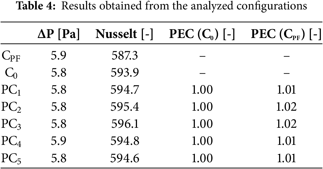
The results of the evaluation of all the configurations are presented in Table 4. It can be observed that the pressure drop of the configurations PC1 to PC5 is practically zero compared to the initial configuration C0, with the maximum increase being only one tenth of a unit for the PC4 configuration. Similarly, there was no significant increase in the Nusselt number, indicating that the translation of the fins does not affect the heat transfer effectiveness. This is determined by the PEC; however, there is an average increase of 1.3% when comparing the results of configurations PC1 to PC5 in comparison to a pin fin heat sink (CPF) under precisely the same conditions.
Due to the fact that the results showed a remarkable proximity between the different configurations, both in terms of pressure drop and Nusselt number, an average analysis of the positions of the geometric configurations was chosen [24–26].
The average execution of the positions is based on the need to consolidate and simplify the information, given the consistency observed in the results obtained. Such consistency suggests that variations in the positions of the configurations do not significantly affect the parameters of interest, justifying the adoption of an average approach to represent more concisely the joint behavior of geometric configurations. Table 5 shows the selected geometric configuration (PCoptimal) for the second phase of the research. Fig. 9 shows the PCoptimal. It is important to note that in this figure, the original configuration is highlighted in blue to facilitate the comparison between the two locations.
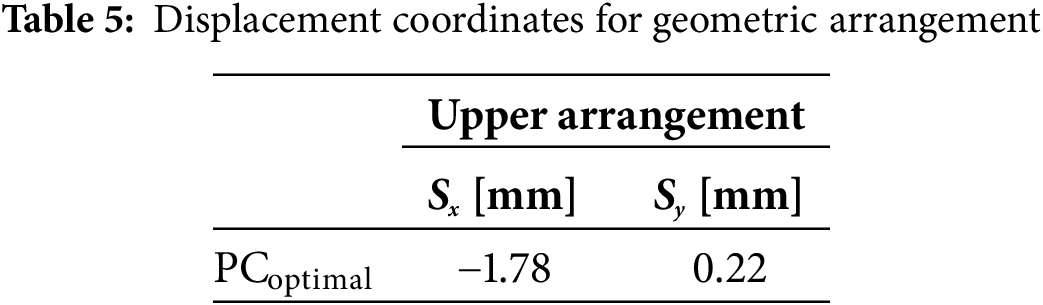
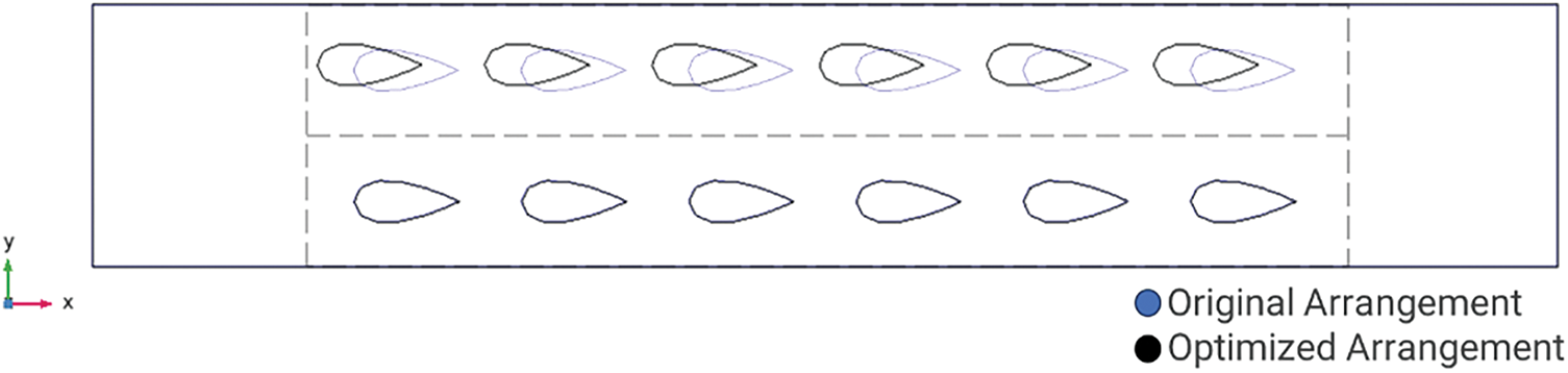
Figure 9: Comparison of the optimized array PCoptimal with the original array C0
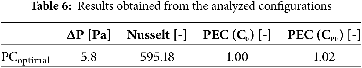
It is well known that the architecture of a NACA profile promotes a smooth flow of the surrounding air, minimizing turbulence zones and aerodynamic drag. In this context, Fig. 10 shows the velocity contours with flow lines derived from the PCoptimal result. In this figure, it can be seen that with the PCoptimal, no vortex zone is formed. Consequently, the pressure drop, as shown in Table 6, does not increase compared to the original C0 configuration. On the other hand, Nu and PEC show an increase of about 0.22% and 0%, respectively, in relation to the original configuration C0. However, with respect to CPF, the Nu and PEC show an increase of about 1.34% and 2%, respectively.

Figure 10: Velocity contour results with the aerodynamic lines of the NACA 0040 heat sink (PCoptimal)
3.2 Multi-Objective Optimization in the Second Stage: Results of Rotation Optimization
As in the first phase, five executions were carried out in the subsequent phase. This measure was taken to avoid the possibility of finding only local minimum and maximum points. Each execution consisted of 40 generations, and each generation consisted of 25 individuals.
Fig. 11 shows the Pareto fronts of the NACA 0040 finned heat sink with the Optimal Position Configuration (PCoptimal), however, these five configurations will be identified as position and rotation configurations. In Fig. 11, it can be seen that the rotated configurations results in the same behavior, i.e., the Nusselt number increases while the pressure drop also increases.
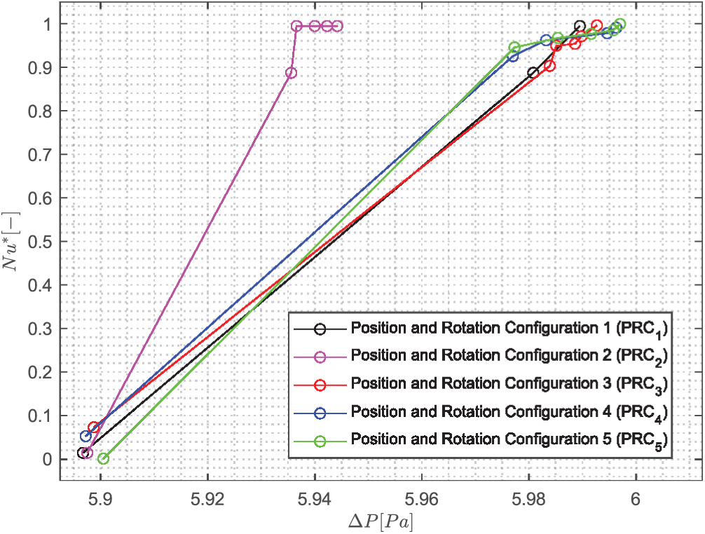
Figure 11: Pareto fronts of the five rotation configurations of the NACA 0040 profile using the PCoptimal
In addition, individuals tend to the maximum pressure drop in 80% of the position and rotation configurations (PRC1 and PRC3 to PRC5), but the corresponding Nusselt number value varies by 10%. The pressure drop for the majority of people in the remaining 20% (PRC2), however, is only 1% smaller than that of the individuals in the earlier setups. While most individuals have not shown a significant change in a Nusselt number. The lowest pressure drop for all rotating configurations is roughly 1.6% lower than the maximum pressure drop, although the Nusselt number remains constant. Consequently, the rotation configurations do not affect the fluid hydrodynamics.
Table 7 shows the five geometric configurations used in the second stage of the study, along with their respective rotation positions around their own z-axis. The configuration (C0) corresponds to the initial configuration, as shown in Fig. 12a, while the configurations PRC1 to PRC5 represent the relative rotation of each optimal configuration. Fig. 12b shows these configurations relative to the initial configuration C0.
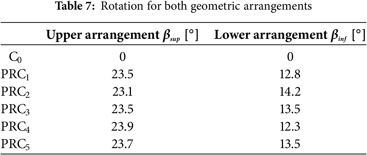

Figure 12: NACA 0040 profile location: (a) original configuration (C0), (b) configurations PRC1 to PRC5 compared to C0
The results of the evaluation of the above configurations are presented in Table 8 and they are interesting because it is observed that the pressure drop of the configurations PRC1 to PRC5 is minimal compared to the original configuration C0, with the maximum increase being only one tenth. On the other hand, comparing the same results with the configurations PC1 to PC5, the effect of the rotation did not influence the pressure drop. However, in the case of the Nusselt number, there was an average increase of 6.5%, with respect to the original configuration C0 and an increase of 7.5%, with respect to the PF configuration.
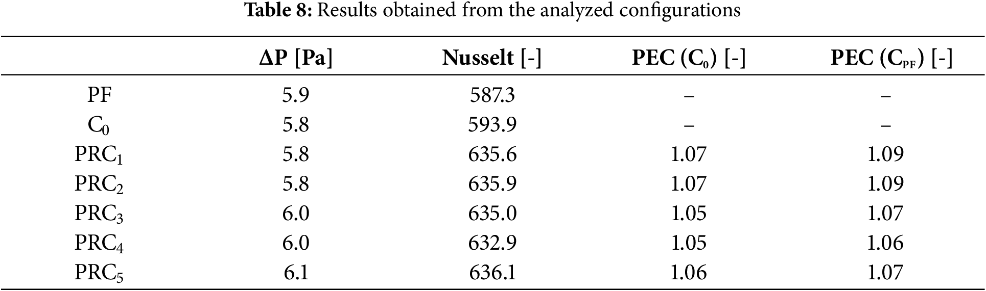
This improvement in heat transfer performance is most clearly seen in the PEC, where it is concluded that by modifying the original array leads to an average increase of 6.0%, and an average increase of 7.6% compared to the PF configuration.
As in the first stage of this work, the results showed a remarkable proximity between the different configurations, both in terms of pressure drop and Nusselt number; therefore, based on the results, an average analysis of the rotation positions of the geometric configurations was chosen.
The average execution of rotations is based on the need to consolidate and simplify the information, given the consistency observed in the results obtained. This consistency suggests that variations in the rotation of the configurations do not significantly affect the parameters of interest, justifying the adoption of an average approach to more concisely represent the joint behavior of geometric configurations.
Table 9 presents the selected geometric configuration, PRCoptimal, while Fig. 13 simultaneously shows PRCoptimal. It is important to note that this figure highlights the original arrangement in blue to facilitate comparison between both locations.
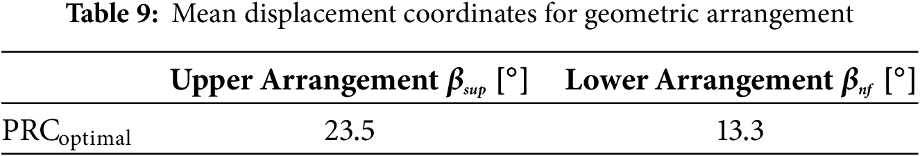

Figure 13: Comparison of PRCoptimal optimized array with the original C0 array
As expected, the rotational effect of both arrangements resulted in the promotion of vortex zones as shown in Fig. 14, however, the PRCoptimal configuration had no significant effect on the aerodynamic drag compared to PCoptimal, i.e., there was no change in pressure drop. On the other hand, the Nusselt number and the PEC show an increase of about 7% with respect to the initial array C0 and 9% with respect to the CPF, as shown in Table 10.

Figure 14: Velocity contour results with the aerodynamic lines of the NACA 0040 heat sink (PRCoptimal)
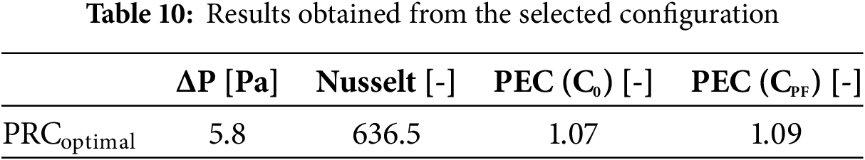
Fig. 15 displays the temperature field. Fig. 15a, for the original Co array, shows how the temperature gradient increases, mainly around the fin area, that is between the leading edge and the end of the fin. A 20 K difference is observed between the entrance and exit of the fin array.


Figure 15: Temperature field (a) for initial configuration C0, (b) for optimal configuration for position PCoptimal, and (c) for optimal configuration of rotation PRC optima
Regarding the temperature field, Fig. 15b allows seeing an area of higher temperature at the end of the heat dissipator, same as in the Co array of Fig. 15a, but somehow having a much better temperature scattering; therefore, it could be said that having an upper arrangement different than the lower fin arrangement leads to better cooling at the core of the dissipator.
The fin rotation is beneficial to the air flow, as can be seen in Fig. 15c, reducing the temperature between the leading edge and the end part of the fin (this can be clearly observed in the figure).
In this paper the use of NACA 0040 airfoils is proposed, aiming to lower the pressure drop while increasing the heat dissipation. The paper also reports a 2-Stage optimization of a heat sink with NACA 0040 profile fins. Displacement (for Stage 1) and rotation (for Stage 2) of each fin were the variables considered in this study. The working fluid was air at
The Pareto fronts obtained in both stages showed similarities, i.e., as the pressure drop increased, the Nusselt number also did. For the first stage, it was observed that the pressure drop of the configurations PC1 to PC5 compared to the C0 and CPF configurations was practically without variation. On the other hand, when comparing the configurations PC1 to PC5 with the CPF configuration, it is found that the improved thermal performance is 2%.
The results of the second stage show that the pressure drop of the configurations PRC1 to PRC5, compared to the configurations C0 and CPF, is minimal, i.e., the effect of rotation did not influence the pressure drop. However, rotation did have an impact on the Nusselt number; in comparison to the C0 and CPF configurations, the efficiency of heat transfer between the air and the heat sink improved by 6.9% and 8.0%, respectively. Furthermore, when comparing the configurations PRC1 to PRC5 with the C0 and CPF configurations, the thermal performance improved by 7% and 9%, respectively.
All results were favorable for the heat sink configurations obtained from the evolutionary algorithm. The All results were favorable for the heat sink configurations obtained from the evolutionary algorithm. The configuration with the best heat transfer effectiveness was PRCoptimal, which provided a slight difference in pressure drop and allowed a PEC of 9%.
The optimization analysis of the geometric arrangement of the proposed NACA 0040 fins for a heat sink resulted in an improvement in the heat transfer between the surface of the heat sink and the surrounding fluid, as well as an improvement in the pressure drop, leading to lower energy costs (energy savings).
Acknowledgement: The authors would like to recognize the financial support of the University of Guanajuato, under the Project Convocatoria Institucional de Investigación Científica 2025, 161/2025.
Funding Statement: This research was funded by University of Guanajuato through Project Convocatoria Institucional de Investigación Científica 2025, 161/2025.
Author Contributions: The authors confirm contribution to the paper as follows: study conception and mathematical formulation: J. Luis Luviano-Ortiz, Julio Cesar Rodriguez-Mosqueda, Salvador Botello-Aceves, Yanan Camaraza-Medina, Abel Hernandez-Guerrero; analysis and interpretation of results: J. Luis Luviano-Ortiz, Julio Cesar Rodriguez-Mosqueda, Salvador Botello-Aceves, Abel Hernandez-Guerrero; draft manuscript preparation: Salvador Botello-Aceves, Yanan Camaraza-Medina, Abel Hernandez-Guerrero. All authors reviewed the results and approved the final version of the manuscript.
Availability of Data and Materials: Not applicable.
Ethics Approval: Not applicable.
Conflicts of Interest: The authors declare no conflicts of interest to report regarding the present study.
Nomenclature
| S | Displacement (mm) |
| Velocity vector (m/s) | |
| P | Pressure (Pa) |
| K | Thermal conductivity (W/m·K) |
| Cp | Specific heat (J/kg·K) |
| Temperature (K) | |
| q’’ | Heat flux (W/m2) |
| C0 | Initial configuration |
| PC | Position configurations |
| PRC | Position and rotation configurations |
| Greek Symbols | |
| β | Rotation fin (°) |
| μ | Viscosity (kg/m·s) |
| ρ | Density (kg/m3) |
| e | Dissipation energy |
| Subscripts | |
| Fluid | |
| Solid | |
| Direction of axis x | |
| Direction of axis y | |
| Sup | Upper |
| Inf | Lower |
References
1. Sahel D, Bellahcene L, Yousfi A, Subasi A. Numerical investigation and optimization of a heat sink having hemispherical pin fins. Int Commun Heat Mass Transf. 2021;122(13):105133. doi:10.1016/j.icheatmasstransfer.2021.105133. [Google Scholar] [CrossRef]
2. Rao AK, Somkuwar V. Investigation of taper sloped fin for heat transfer enhancement in plate fin heat sink. Mater Today Proc. 2022;51(6):422–9. doi:10.1016/j.matpr.2021.05.567. [Google Scholar] [CrossRef]
3. Pujol T, T’Jollyn I, Massaguer E, Massaguer A, Cózar IR, De Paepe M. Design optimization of plate-fin heat sink with forced convection for single-module thermoelectric generator. Appl Therm Eng. 2023;221(5):119866. doi:10.1016/j.applthermaleng.2022.119866. [Google Scholar] [CrossRef]
4. Tariq A, Altaf K, Ahmad SW, Hussain G, Ratlamwala TAH. Comparative numerical and experimental analysis of thermal and hydraulic performance of improved plate fin heat sinks. Appl Therm Eng. 2021;182(1–2):115949. doi:10.1016/j.applthermaleng.2020.115949. [Google Scholar] [CrossRef]
5. Freegah B, Hussain AA, Falih AH, Towsyfyan H. CFD analysis of heat transfer enhancement in plate-fin heat sinks with fillet profile: investigation of new designs. Therm Sci Eng Prog. 2020;17(9–10):100458. doi:10.1016/j.tsep.2019.100458. [Google Scholar] [CrossRef]
6. Nilpueng K, Mesgarpour M, Asirvatham LG, Dalkılıç AS, Ahn HS, Mahian O, et al. Effect of pin fin configuration on thermal performance of plate pin fin heat sinks. Case Stud Therm Eng. 2021;27:101269. doi:10.1016/j.csite.2021.101269. [Google Scholar] [CrossRef]
7. Pandey J, Husain A, Zahid Ansari M, Al-Azri N. Performance analysis of cold plate heat sink with parallel channel and pin-fin. Mater Today Proc. 2021;44(2):3144–9. doi:10.1016/j.matpr.2021.02.819. [Google Scholar] [CrossRef]
8. Ahmadian-Elmi M, Mashayekhi A, Nourazar SS, Vafai K. A comprehensive study on parametric optimization of the pin-fin heat sink to improve its thermal and hydraulic characteristics. Int J Heat Mass Transf. 2021;180:121797. doi:10.1016/j.ijheatmasstransfer.2021.121797. [Google Scholar] [CrossRef]
9. Altaf K, Tariq A, Ahmad SW, Hussain G, Ratlamwala TAH, Ali HM. Thermal and hydraulic analysis of slotted plate fins heat sinks using numerical and experimental techniques. Case Stud Therm Eng. 2022;35(1–2):102109. doi:10.1016/j.csite.2022.102109. [Google Scholar] [CrossRef]
10. Razavi SE, Osanloo B, Sajedi R. Application of splitter plate on the modification of hydro-thermal behavior of PPFHS. Appl Therm Eng. 2015;80(2):97–108. doi:10.1016/j.applthermaleng.2015.01.046. [Google Scholar] [CrossRef]
11. Sajedi R, Osanloo B, Talati F, Taghilou M. Splitter plate application on the circular and square pin fin heat sinks. Microelectron Reliab. 2016;62(20):91–101. doi:10.1016/j.microrel.2016.03.026. [Google Scholar] [CrossRef]
12. Hosseinirad E, Khoshvaght-Aliabadi M, Hormozi F. Effects of splitter shape on thermal-hydraulic characteristics of plate-pin-fin heat sink (PPFHS). Int J Heat Mass Transf. 2019;143:118586. doi:10.1016/j.ijheatmasstransfer.2019.118586. [Google Scholar] [CrossRef]
13. Abadi M, Ranjbar AA, Gorzin M, Bahrampoury R, Hosseini MJ. Effect of splitter angles and orientations attached to pin fin on heat transfer and hydraulic characteristics in a jet impingement rectangular channel. Alex Eng J. 2023;62(2):475–88. doi:10.1016/j.aej.2022.07.045. [Google Scholar] [CrossRef]
14. Maji A, Deshamukhya T, Choubey G, Choubey A. Performance evaluation of perforated pin fin heat sink using particle swarm optimization and MCDM techniques. J Therm Anal Calorim. 2022;147(8):5133–50. doi:10.1007/s10973-021-10872-6. [Google Scholar] [CrossRef]
15. Huang CH, Huang YR. An optimum design problem in estimating the shape of perforated pins and splitters in a plate-pin-fin heat sink. Int J Therm Sci. 2021;170:107096. doi:10.1016/j.ijthermalsci.2021.107096. [Google Scholar] [CrossRef]
16. Shen B, Li Y, Yan H, Boetcher SKS, Xie G. Heat transfer enhancement of wedge-shaped channels by replacing pin fins with Kagome lattice structures. Int J Heat Mass Transf. 2019;141:88–101. doi:10.1016/j.ijheatmasstransfer.2019.06.059. [Google Scholar] [CrossRef]
17. Jin W, Wu J, Jia N, Lei J, Ji W, Xie G. Effect of shape and distribution of pin-fins on the flow and heat transfer characteristics in the rectangular cooling channel. Int J Therm Sci. 2021;161(4):106758. doi:10.1016/j.ijthermalsci.2020.106758. [Google Scholar] [CrossRef]
18. Ho JY, Wong KK, Leong KC, Wong TN. Convective heat transfer performance of airfoil heat sinks fabricated by selective laser melting. Int J Therm Sci. 2017;114:213–28. doi:10.1016/j.ijthermalsci.2016.12.016. [Google Scholar] [CrossRef]
19. Soleymani Z, Rahimi M, Gorzin M, Pahamli Y. Performance analysis of hotspot using geometrical and operational parameters of a microchannel pin-fin hybrid heat sink. Int J Heat Mass Transf. 2020;159(4):120141. doi:10.1016/j.ijheatmasstransfer.2020.120141. [Google Scholar] [CrossRef]
20. Yu X, Woodcock C, Plawsky J, Peles Y. An investigation of convective heat transfer in microchannel with Piranha Pin Fin. Int J Heat Mass Transf. 2016;103(3):1125–32. doi:10.1016/j.ijheatmasstransfer.2016.07.069. [Google Scholar] [CrossRef]
21. Mehrpooya M, Mirmotahari SR, Ghafoorian F, Karimkhani M, Ganjali MR. Investigation of a packed bed energy storage system with different PCM configurations and heat transfer enhancement with fins using CFD modeling. Chem Pap. 2024;78(4):2453–67. doi:10.1007/s11696-023-03251-y. [Google Scholar] [CrossRef]
22. Mehrpooya M, Ghafoorian F, Mohammadi Afzal SP, Mirmotahari SR, Ganjali MR. A comprehensive transient heat transfer simulation of U-tube borehole heat exchanger considering porous media and subterranean water seepage. Chem Pap. 2024;78(11):6315–29. doi:10.1007/s11696-024-03443-0. [Google Scholar] [CrossRef]
23. Chin SB, Foo JJ, Lai YL, Yong TK. Forced convective heat transfer enhancement with perforated pin fins. Heat Mass Transf. 2013;49(10):1447–58. doi:10.1007/s00231-013-1186-z. [Google Scholar] [CrossRef]
24. Camaraza-Medina Y, Sánchez Escalona AA, Miguel Cruz-Fonticiella O, García-Morales OF. Method for heat transfer calculation on fluid flow in single-phase inside rough pipes. Therm Sci Eng Prog. 2019;14(3):100436. doi:10.1016/j.tsep.2019.100436. [Google Scholar] [CrossRef]
25. Camaraza-Medina Y, Rubio-Gonzales Á, Cruz-Fonticiella O, García-Morales O. Simplified analysis of heat transfer through a finned tube bundle in air cooled condenser. Math Model Eng Probl. 2018;5(3):237–42. doi:10.18280/mmep.050316. [Google Scholar] [CrossRef]
26. Camaraza-Medina Y. Methods for the determination of the heat transfer coefficient in air cooled condenser used at biomass power plants. Int J Heat Technol. 2021;39(5):1443–50. doi:10.18280/ijht.390505. [Google Scholar] [CrossRef]
Cite This Article
 Copyright © 2025 The Author(s). Published by Tech Science Press.
This work is licensed under a Creative Commons Attribution 4.0 International License , which permits unrestricted use, distribution, and reproduction in any medium, provided the original work is properly cited.
 Downloads
 Citation Tools